Instrumentation for Tests of General Relativity By the BepiColombo Mission Sami Asmar Jet Propulsion Laboratory, California Institute of Technology Luciano Iess University of Rome, Italy And the Mercury Orbiter Radio-science Experiment (MORE) Team 8 July 2008 From Quantum to Cosmos 3 Airlie Center, Warrenton, Virginia
Transcript
Instrumentation forTests of General Relativity
By the BepiColombo Mission
Sami AsmarJet Propulsion Laboratory,California Institute of Technology
Luciano IessUniversity of Rome, Italy
And the Mercury OrbiterRadio-science Experiment (MORE) Team
8 July 2008From Quantum to Cosmos 3
Airlie Center, Warrenton, Virginia
• ESA’s Mercury Planetary Orbiter(MPO) selected an internationalRadio Science Team to:
– Determine the gravitational field ofMercury and investigate the interiorstructure
– Investigate aspects of the theory ofgeneral relativity
• Radio Science technique utilizehighly stable (low noise) radiolinks between spacecraft andground stations
Introduction
Luciano Iess Università di Roma La SapienzaSami Asmar Jet Propulsion Laboratory
John W. Armstrong Jet Propulsion LaboratoryNeil Ashby University of ColoradoJean Pierre Barriot CNESPeter Bender University of ColoradoBruno Bertotti Università di PaviaThibault Damour Institut des Hautes Etudes ScientifiquesVeronique Dehant Observatoire de BruxellesPeter W. Kinman Case Western Reserve UniversityAlex Konopliv Jet Propulsion LaboratoryAnne Lemaitre University of NamurAndrea Milani Comparetti Università di PisaPaolo Tortora Università di BolognaTilman Spohn Westfälische Wilhelms-UniversitätDavid Vokroulicky Charles University, PragueMichael Watkins Jet Propulsion LaboratoryXiaoping Wu Jet Propulsion Laboratory
M RE Mercury Orbiter Radio-science Experiment
Testing gravitational theories
Solar Gravity
Deflection of light
Time delay Frequency shift
rad)1(104)1(26
b
R
b
Mgr
sunsun !!" +#=+=$
tll
tllMt
sun
!+
+++="
10
10ln)1( #!
+"+
+=
#b
b
M
ll
lvlvsun)1(42
10
1001 $%&
&
= 72 km for a grazing beam ≈ 8×10⁻¹⁰ for a grazing beam
Simulation Results
3×10–13 per year9×10–13 per yearG dot / G
4.8 × 10–94 × 10–8Solar J2
7.8 × 10–61 × 10–4α1
2 × 10–55 × 10–4η
7 × 10–61.2 × 10–4β
2 × 10–62.3 × 10–5γ
MORE AccuracyPresent AccuracyParameter
Simulations show
• Results are achievable with range and range-rate(Doppler) measurements at X- and Ka-bandsimultaneously
• Ka-band ranging accuracy to 20 cm• Range-rate accuracy to ~ 3 microns/s at 1000 s• Gamma in cruise-phase solar conjunction with
quiet spacecraft (no engine pulsing)• Other parameters in one year of orbital phase
1. Instrumental: random errors in hardwaresystems
– Phase fluctuations in link– Electronic components– Noise of frequency standard– Antenna mechanical noise
2. Dynamical:• Un-modeled bulk motion of spacecraft or ground
station3. Propagation:
– Solar Wind– Ionosphere– Troposphere
4. Systematic errors
Classification of Noise Sources
MORE Measurements!
• The range & range rate between spacecraft and ground stations– Removing the effects of the plasma along the path by means of a multi-
frequency (X- and in Ka-bands) links
• The non-gravitational perturbations acting on the spacecraft, bymeans of the accelerometer
• The absolute attitude of the spacecraft, in a stellar frame ofreference, by means of star trackers
• The angular displacement, with respect to previous trackingpasses, of surface landmarks, by means of pattern matchingbetween images
• One-way propagationnoise atS-, X-, and Ka-bands asfunction of angulardistance from the Sun(developed by J.W.Armstrong, published inAsmar et al., 2005)
• FKa/FX = ~4
• Improvement by factor~42
Why Ka-band
RMS range rate residuals: 2x10⁻⁶ m/s @ 300 s
γ= 1 + (2.1 ± 2.3)×10-5
γViking = 1x10⁻³
Method Successfully Demonstrated by Cassini
B.Bertotti, L.Iess, P.Tortora, “A test of general relativity using radio links with theCassini spacecraft” Nature, 425, 25 Sept. 2003, p. 374
Plasma noise in the X/X, X/Ka, Ka/Ka links and thecalibrated Doppler observable
• Doppler Quality fromthree links from CassiniRadio Science
• For illustration only
• Improvements over X/X
• X/K 40% (this linkonly back-up)
• K/K factor of 16
• K/K calibrated usingX/X not shown
Example: Cassini Data Calibration
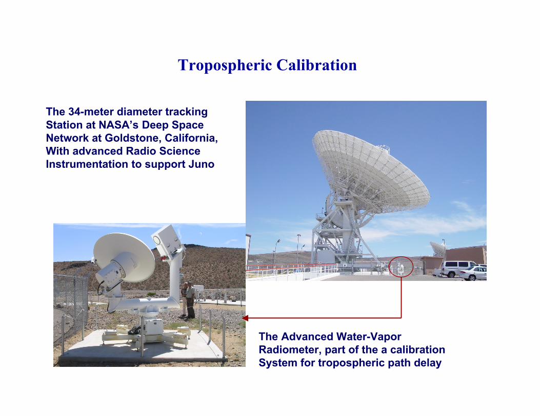
The 34-meter diameter trackingStation at NASA’s Deep SpaceNetwork at Goldstone, California,With advanced Radio Science Instrumentation to support Juno
The Advanced Water-VaporRadiometer, part of the a calibrationSystem for tropospheric path delay
Tropospheric Calibration
Tropospheric Calibration Example
• Doppler Quality fromCassini Radio Science
• Blue curve illustratesincreased water-vaporcontribution at lowelevation angles
• Green curve illustratesthe same Dopplerresiduals after applyingthe water-vaporradiometer calibration
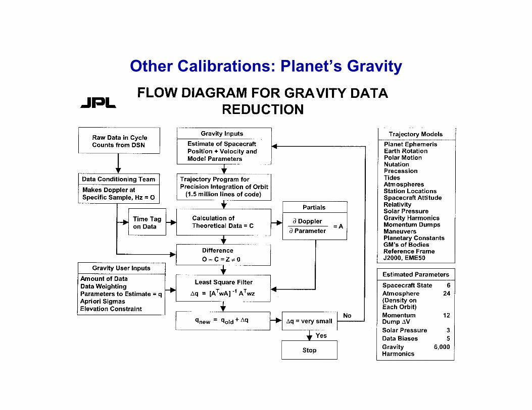
Other Calibrations: Planet’s Gravity
The challenge:An Advanced Ranging Instrument
• Deep space range measurements are typically based on sequential procedure• Ranging signal phase modulates the uplink carrier; spacecraft transponder
demodulates and recovers and retransmits to ground by phase modulatingthe downlink carrier– The tone/code at highest frequency defines the accuracy while the others
are sequentially applied for ambiguity resolution• A new design utilizes Ka-band uplink and downlink to minimize the largest
error source due to interplanetary plasma– PN ranging; 24 MHz bandwidth for station exciter system; utilizes an
open-loop receiver– More precise and frequent calibration of delay in electronics– Etc.
X-band DownConverter
Ka-bandExciter
X-bandTransmitter
X-bandExciter
Multi-bandRanging
Assembly
IF Signal Distribution
UplinkRanging
Assembly
Frequency & Timing
Modified
New
Existing
Uplink Downlink
TelemetryReceiver
Radio ScienceReceiver
Ka-band DownConverter
Ka-BandCarrier
Synthesis
AdvancedWater VaporRadiometer
Ka-bandTransmitter
UplinkRanging
Assembly
DigitalCarrier
Synthesis
Overview of ProposedAdvanced Ranging Instrument
Conclusion• BepiColombo will provide excellent science with relatively inexpensive
instrumentation
• Same instrumentation used for geodesy/geophysics and GR
• Results available after its first year of nominal mission
• BC-MORE will reach the limits of the microwave instrumentation forinterplanetary radio links
• Team “invented“ a system a decade ago for improved Range-rate– ~ 3microns/s at 1000 s; demonstrated by Cassini
• Now “invented“ a system for improved Ranging– ~ 20 cm; yet to be demonstrated
• Pushing limits of technology in tracking and Radio Science benefitsall future deep space missions