Page 1
An Approved Continuing Education Provider
PDHonline Course E444 (7 PDH)
_____________________________________________________
Instrumentation & Process Control
Automation Guidebook – Part 3 Instructor: Jurandir Primo, PE
2014
PDH Online | PDH Center
5272 Meadow Estates Drive Fairfax, VA 22030-6658
Phone & Fax: 703-988-0088
www.PDHonline.org www.PDHcenter.com
Page 2
www.PDHcenter.com PDH Course E444 www.PDHonline.org
©2014 Jurandir Primo Page 1 of 91
INSTRUMENTATION & PROCESS CONTROL AUTOMATION GUIDEBOOK – PART 3
CONTENTS:
1. INTRODUCTION
2. INSTRUMENTATION & CONTROL SYSTEMS
3. INSTRUMENTATION DESCRIPTION & APPLICATION
4. PROCESS CONTROL INSTRUMENTATION
5. CONDUCTIVITY & ANALYTICAL INSTRUMENTATION
6. CONTROL VALVES & INSTRUMENTATION
7. STANDARD & CONTROL VALVES APPLICATION
8. VALVES ACTUATORS, POSITIONERS & TRANSDUCERS
9. CONTROL SYSTEMS & FIELDBUS TECHNIQUES
10. DIAGNOSTICS & COMMUNICATION INTERFACES
11. HAZARDOUS CLASSIFICATION & PROTECTION TYPES
12. PROCESS & PIPING INSTRUMENTATION DIAGRAMS
13. PROCESS CONTROL & SOFTWARE SIMULATIONS
14. REFERENCES & LINKS
Page 3
www.PDHcenter.com PDH Course E444 www.PDHonline.org
©2014 Jurandir Primo Page 2 of 91
1. INTRODUCTION:
Instrumentation is the science of automated measurement and control, or can be defined as the sci-
ence that applies and develops techniques for measuring and controls of equipment and industrial
processes. Process control has a broad concept and may be applied to any automated systems
such as, a complex robot or to a common process control system as a pneumatic valve controlling
the flow of water, oil or steam in a pipe.
A basic instrument consists of three elements:
Sensor or Input Device
Signal Processor
Receiver or Output Device
To measure a quantity, usually is transmitted a signal representing the required quantity to an indi-
cating or computing device where either human or automated action takes place. If the controlling
action is automated, the computer sends a signal to a final controlling device which then influences
the quantity being measured. The physical components commonly measured are:
Temperature, Pressure, Speed, Flow, Force, Movement, Velocity and Acceleration, Stress
and Strain, Level or Depth, Mass or Weight Density, Size or Volume, Acidity/Alkalinity.
Sensors may operate simple on/off switches to detect the following:
Objects (proximity switch), empty or full (level switch), hot or cold (thermostat), pressure high
or low (pressure switch).
Most modern analogue equipment works on the following standard signal ranges.
The accepted industrial standard for electronic signals is a 4 to 20 mA current signal that
represents the 0% to 100% process condition.
The standard industrial range for pneumatic signals is 20 to 100 kPa (3 – 15 psig), which
corresponds to a 0% to 100% process condition.
Note: The live zero (4 mA) is used to distinguish between 0% process (4 mA) and an interrupted or
faulted signal loop (0 mA). The live zero (20 kPa) allows the control room personnel to distinguish
between a valid process condition of 0% (or a 20 kpa(g) reading) and a disabled transmitter or inter-
rupted pressure line (or a 0 kpa(g) reading), providing a coarse rationality verification.
The main motive that pneumatic signals are commonly used in process industries is for safe envi-
ronment, especially when there is a risk of fire or explosion. The advantage of having a standard
range or using digital signals is that all equipment may be purchased ready calibrated. For analogue
systems the minimum signal (temperature, speed, force, pressure and so on) is represented by 4
mA or 0.2 bar (3 psig), and the maximum signal is represented by 20 mA or 1.0 bar (15 psig). Older
Page 4
www.PDHcenter.com PDH Course E444 www.PDHonline.org
©2014 Jurandir Primo Page 3 of 91
electrical equipment use 0 to 10 V. Increasingly the instruments are digital with a binary digital en-
coder built in to give a binary digital output.
The control devices usually take one of the following forms:
Control valves (example, for throttling the flow rate of a fluid);
Electric motors;
Electric heaters.
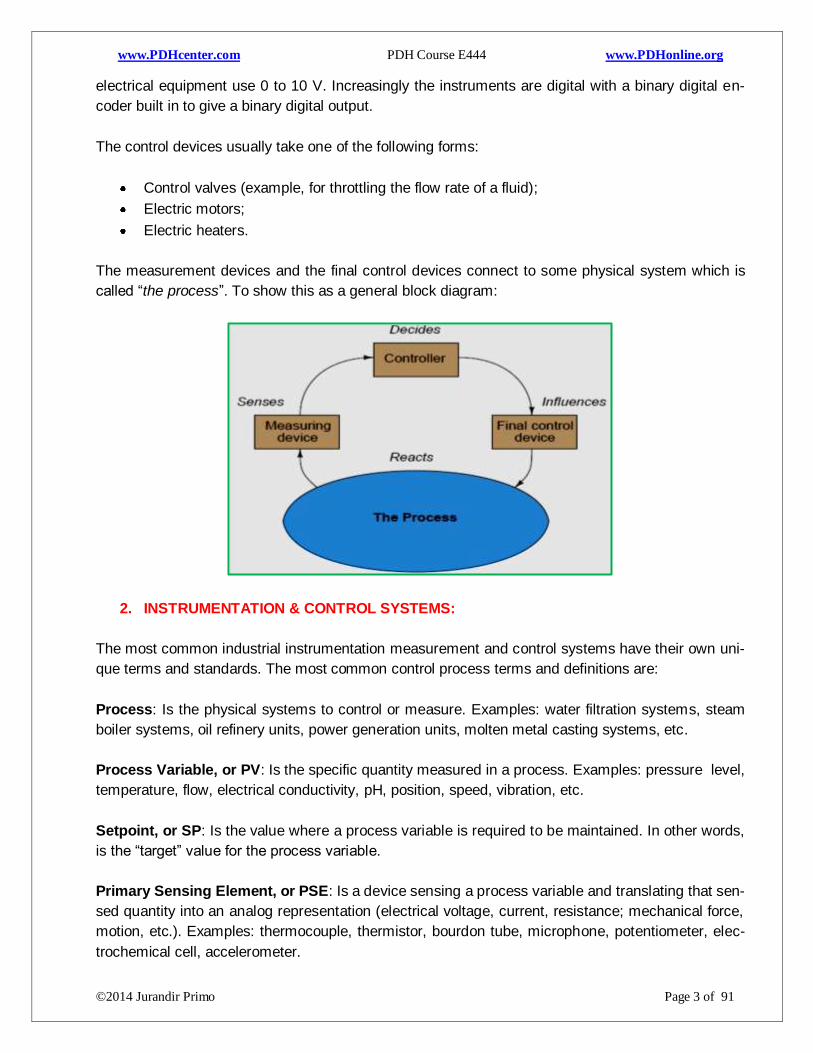
The measurement devices and the final control devices connect to some physical system which is
called “the process”. To show this as a general block diagram:
2. INSTRUMENTATION & CONTROL SYSTEMS:
The most common industrial instrumentation measurement and control systems have their own uni-
que terms and standards. The most common control process terms and definitions are:
Process: Is the physical systems to control or measure. Examples: water filtration systems, steam
boiler systems, oil refinery units, power generation units, molten metal casting systems, etc.
Process Variable, or PV: Is the specific quantity measured in a process. Examples: pressure level,
temperature, flow, electrical conductivity, pH, position, speed, vibration, etc.
Setpoint, or SP: Is the value where a process variable is required to be maintained. In other words,
is the “target” value for the process variable.
Primary Sensing Element, or PSE: Is a device sensing a process variable and translating that sen-
sed quantity into an analog representation (electrical voltage, current, resistance; mechanical force,
motion, etc.). Examples: thermocouple, thermistor, bourdon tube, microphone, potentiometer, elec-
trochemical cell, accelerometer.
Page 5
www.PDHcenter.com PDH Course E444 www.PDHonline.org
©2014 Jurandir Primo Page 4 of 91
Transducer: Is a device converting one standardized instrumentation signal into another standard-
ized instrumentation signal, and/or performing some sort of processing on that signal. Often referred
to as a converter and sometimes as a “relay.” Examples: I/P converter (converts 4-20 mA electric
signal into 3-15 PSI pneumatic signal), P/I converter (converts 3-15 PSI pneumatic signal into 4-20
mA electric signal), square-root extractor (calculates the square root of an input signal).
Note: in general, the “transducer” is any device converting one form of energy into another, such as
a microphone or a thermocouple. In industrial instrumentation, however, is generally used “the pri-
mary sensing element” to describe this concept and reserve the word “transducer” to specifically
refer to a conversion device for standardized instrumentation signals.
Transmitter: Is a device translating the signal produced by a “primary sensing element” (PSE) into
a standardized instrumentation signal such as 3-15 PSI air pressure, 4-20 mA DC electric current,
Fieldbus digital signal packet, etc., which may then, be conveyed to an indicating device, a control-
ling device, or both.
Lower and Upper-Range Values (LRV and URV): Are the values of a process measured in 0%
and 100% of a transmitter’s calibrated range. For example, if a temperature transmitter is calibrated
to measure a range of temperature starting at 300ºC and ending at 500ºC, its LRV would be 300ºC
and its URV would be 500ºC.
Zero and Span: Are the alternative descriptions of LRV and URV for the 0% and 100% points of an
instrument’s calibrated range. “Zero” refers to the beginning-point of an instrument’s range (equiva-
lent to LRV), while “Span” refers to the width of its range (URV − LRV). For example, if a tempera-
ture transmitter is calibrated to measure a range of temperature starting at 300ºC and ending at
500ºC, its zero would be 300ºC and its “span” would be 200ºC.
Controller: Is a device receiving a process variable (PV) signal from a primary sensing element
(PSE) or transmitter, compares the signal to a desired value (called the setpoint), and calculates an
appropriate output signal value to be sent to a final control element (FCE), such as an electric motor
or control valve.
Final Control Element, or FCE: Is a device receiving the signal output by a controller that directly
influences the process. Examples: variable-speed electric motor, control valve, electric heater.
Manipulated Variable, or MV: Is another term to describe the output signal generated by a control-
ler. Is the signal commanding (“or manipulating”) the final control element to influence the process.
Automatic Mode: Is when the controller generates an output signal based on the relationship of a
process variable (PV) to the setpoint (SP).
Manual Mode: Is when the controller’s decision is bypassed, to let a human operator directly deter-
mine the output signal sent to the final control element.
Page 6
www.PDHcenter.com PDH Course E444 www.PDHonline.org
©2014 Jurandir Primo Page 5 of 91
Tag Numbers: Are letters and numbers placed within or near the instrument to identify the type and
function of the device. The letters and numbers placed within or near the instrument to identify the
type and function of the device.
Pressure
Level
Flow
Temperature
Indicator
Recorder
Controller
Transmitter
Diagram Balloon: On a process control diagram, a circle, called as “balloon”, is used to indicate an
instrument, as the “temperature transmitter”, as shown below:
Examples of “balloons” and the respective instruments:
Page 7
www.PDHcenter.com PDH Course E444 www.PDHonline.org
©2014 Jurandir Primo Page 6 of 91
If the balloon is inside a square, the instrument is identified as a “shared
device
Symbols without horizontal lines indicate the instrument is installed in the
field, either: At the point of measurement. Near the final control element.
Symbols with a single line indicate the instrument is mounted on a panel
board, accessible to the operator or for routine maintenance.
If a hexagon is indicated instead of a balloon, a computer function should
be used.
A rhombus inside a square identifies the application of a PLC – Pro-
grammable Logic Controller.
Double lines indicate the instrument is at an auxiliary location away from
the process
Symbols with a single dashed line indicate the instrument is located be-
hind a panel and not easily accessible.
Examples of instruments, PLC and control panels:
ISA - Instrument Functions and Identifications: The ISA standard covers the identification of in-
struments or control functions associated with it in a loop. The user is free to apply additional ident i-
Page 8
www.PDHcenter.com PDH Course E444 www.PDHonline.org
©2014 Jurandir Primo Page 7 of 91
fication, by serial number, unit number, area number, plant number, or by other means. For a more
complete treatment, see ISA-S51.1 and the ISA-S75 series of standards. Examples:
Alarm: A device or function that signals the existence of an abnormal condition by means of an au-
dible or visible discrete change, or both, intended to attract attention. Its operation is simply to close
or open a circuit that may or may not be used for normal or abnormal interlock, start-up, shutdown,
of a pilot light or an alarm device, properly designated as a level switch, a flow switch, etc.,.
Binary: A term applied to a signal or device that has only two discrete positions or states. When
used in its simplest form, as in "binary signal" (as opposed to "analog signal"), the term denotes an
"on-off" or "high-low" state, i.e., one which does not represent continuously varying quantities.
Board: Synonym for control panel.
Bubble: Is a circular symbol used to denote and identify the purpose of an instrument or function,
synonym for balloon. It may contain a tag number.
Controller: A device having an output that varies to regulate a controlled variable in a specified
manner. The automatic controller varies its output automatically in response to a direct or indirect
input of a measured process. The manual controller is a manual loading station and its output is not
dependent on a measured process, but can be varied only by manual adjustment.
Control Station: A manual loading station that also provides switching between manual and auto-
matic control modes of a control loop. It is also known as an auto-manual station. The operator inter-
face of a distributed control system may be regarded as a control station.
Control Valve: A hand-actuated on-off valve, or a self-actuated check valve that directly manipu-
lates the flow of one or more fluid process streams. It is expected that use of the designation "hand
control valve" will be limited to hand-actuated valves that are used for process throttling, or require
identification as an instrument.
Converter: A device that receives information in one form of an instrument signal and transmits an
output signal in another form. Typically, a temperature element (TE) may connect to a transmitter
(TT), not to a converter (TY). A converter is also referred to as a transducer; however, "transducer"
is a completely general term, but its use for signal conversion is not recommended.
Digital: A term applied to a signal or device that uses binary digits to represent continuous values or
discrete states.
Distributed Control System: A system which, while being functionally integrated, consists of sub-
systems which may be physically separate and remotely located from one another.
Final Control Element: The device that directly controls the value of the manipulated variable of a
control loop. Often the final control element is a control valve.
Page 9
www.PDHcenter.com PDH Course E444 www.PDHonline.org
©2014 Jurandir Primo Page 8 of 91
Function: The purpose of, or an action performed by, a device.
Identification: The sequence of letters or digits, or both, used to designate an individual instrument
or loop.
Instrument: A device used directly or indirectly to measure and/or control a variable. The term in-
cludes primary elements, final control elements, computing devices, and electrical devices such as
annunciators, switches, and pushbuttons.
Instrumentation: A collection of instruments or their application for the purpose of observation,
measurement, control, or any combination of these.
Loop: A combination of two or more instruments or control functions arranged so that signals pass
from one to another for the purpose of measurement and/or control of a process variable.
Manual Loading Station: A device or function having a manually adjustable output that is used to
actuate one or more remote devices. The station may have integral indicators, lights, or other fea-
tures. It is also known as a manual station or a manual loader.
Measurement: The determination of the existence or the magnitude of a variable.
Monitor: A general term for an instrument or instrument system used to measure or sense the sta-
tus or magnitude of one or more variables for the purpose of deriving useful information. Monitor can
also be used as a verb.
Monitor Light: Synonym for pilot light.
Panel: A structure that has a group of instruments mounted on it, houses the operator-process inter-
face, and is chosen to have a unique designation. The panel may consist of one or more sections,
cubicles, consoles, or desks.
Panel-Mounted: A term applied to an instrument that is mounted on a panel or console and is ac-
cessible for an operator's normal use. A function that is normally accessible to an operator in a
shared-display system is the equivalent of a discrete panel-mounted device.
Pilot Light: A light that indicates which of a number of normal conditions of a system or device ex-
ists. It is unlike an alarm light, which indicates an abnormal condition. The pilot light is also known as
a monitor light.
Primary Element: Synonym for sensor.
Process: Any operation or sequence of operations involving a change of energy, state, composi-
tion, dimension, or other properties that may be defined with respect to a datum.
Page 10
www.PDHcenter.com PDH Course E444 www.PDHonline.org
©2014 Jurandir Primo Page 9 of 91
Process Variable: Any variable property of a process. The term process variable is used in this
standard to apply to all variables other than instrument signals.
Program: A repeatable sequence of actions that defines the status of outputs as a fixed relationship
to a set of inputs.
Programmable Logic Controller: A controller, usually with multiple inputs and outputs, that con-
tains an alterable program.
Relay: A device whose function is to pass on information in an unchanged form or in some modified
form. Relay is often used to mean computing device. The latter term is preferred. The term "relay"
also is applied specifically to an electric, pneumatic, or hydraulic switch that is actuated by a signal.
The term also is applied to functions performed by a relay.
Scan: To sample, in a predetermined manner, each of a number of variables intermittently. The
function of a scanning device is often to ascertain the state or value of a variable. The device may
be associated with other functions such as recording and alarming.
Sensor: That part of a loop or instrument that first senses the value of a process variable, and that
assumes a corresponding, predetermined, and intelligible state or output. The sensor may be sepa-
rate from or integral with another functional element of a loop. The sensor is also known as a detec-
tor or primary element.
Set Point: An input variable that sets the desired value of the controlled variable. The set point may
be manually set, automatically set, or programmed. Its value is expressed in the same units as the
controlled variable.
Shared Controller: A controller, containing preprogrammed algorithms that are usually accessible,
configurable, and assignable. It permits a number of process variables to be controlled by a single
device.
Shared Display: The operator interface device (usually a video screen) used to display process
control information from a number of sources at the command of the operator.
Switch: A device that connects, disconnects, selects, or transfers one or more circuits and is not
designated as a controller, a relay, or a control valve. As a verb, the term is also applied to the func-
tions performed by switches.
Test Point: A process connection to which no instrument is permanently connected, but which is
intended for the temporary or intermittent connection of an instrument.
Transducer: A general term for a device that receives information in the form of one or more physi-
cal quantities, modifies the information and/or its form, if required, and produces a resultant output
signal. Depending on the application, the transducer can be a primary element, transmitter, relay,
Page 11
www.PDHcenter.com PDH Course E444 www.PDHonline.org
©2014 Jurandir Primo Page 10 of 91
converter or other device. Because the term "transducer" is not specific, its use for specific applica-
tions is not recommended.
Transmitter: A device that senses a process variable through the medium of a sensor and has an
output whose steady-state value varies only as a predetermined function of the process variable.
The sensor may or may not be integral with the transmitter.
Identification Designation: Based on Standard ANSI/ISA S5.1 and ISO 14617-6, the P&ID is used
for the identification of measurements within the process. The identifications consist of up to 5 let-
ters. The first identification letter is for the measured value, the second is a modifier, 3rd indicates
passive/readout function, 4th - active/output function, and the 5th is the function modifier.
Letter Measured value Modifier Readout/Passive function
Output/active function)
Function modifier)
A Analysis Alarm
B Burner, combustion User choice User choice User choice
C User's choice (usu-ally conductivity)
Control Close
D User's choice (usu-ally density)
Difference Deviation
E Voltage Sensor
F Flow rate Ratio
G User's choice (usu-ally gaging/gauging)
Gas Glass/gauge /viewing
H Hand High
I Current Indicate
J Power Scan
K Time, time schedule Time rate of change
Control station
L Level Light Low
M User's choice Middle / in-termediate
N User's choice (usu-
ally torque)
User choice User choice User choice
O User's choice Orifice Open
Page 12
www.PDHcenter.com PDH Course E444 www.PDHonline.org
©2014 Jurandir Primo Page 11 of 91
P Pressure Point/test connec-
tion
Q Quantity Totalize Integrate
Totalize/integrate
R Radiation Record Run
S Speed, frequency Safety Switch Stop
T Temperature Transmit
U Multivariable Multifunction Multifunction
V Vibration, mechani-cal analysis
Valve or damper
W Weight, force Well or probe
X User's choice (usu-ally on-off valve as
XV)
X-axis Accessory devic-es, unclassified
Unclassified Unclassified
Y Event, state, pres-ence
Y-axis Auxiliary devices
Z Position, dimension Z-axis Actuator, driver or
unclassified final control element
Note: For reference designation of any equipment in industrial systems the standard IEC 61346 (In-
dustrial systems, installations and equipment and industrial products - Structuring principles and
reference designations) can be applied. For the function measurement, the reference designator B
is used, followed by the above listed letter for the measured variable.
Process Variables: Industries such as petrochemical, steel, food, paper, and so on, where the in-
strumentation is responsible for the maximum yield of a process, causing that all energy be trans-
formed into a controlled work. There are many types of instrumentation, as can be seen in the table
above. Our main subject is only process control. Thus, the main variables that reflect energy trans-
fers in the process controls are: pressure, level, flow and temperature; called as process variables.
These systems may need to be identified on drawings and in text. As an example, the system codes for identification may be the following:
ACS = Analyzer Control System BMS = Burner Management System CCS = Computer Control System CEMS = Continuous Emissions Monitoring System
DCS = Distributed Control System FDS = Flame Detection System MMS = Machine Monitoring System VMS = Vibration Monitoring System
Loop Diagram: The instruments can be interconnected with each other to accomplish a certain task in industrial processes. The association of these instruments is called “loop diagram” where each instrument performs a function, as shown below:
Page 13
www.PDHcenter.com PDH Course E444 www.PDHonline.org
©2014 Jurandir Primo Page 12 of 91
Instrument Tag Letters: Provides the allowable loop identification letters and combinations accord-
ing to the loop identification number construction schemes. The letters and combinations shall have
the mandatory meanings are given by ISA S5.1 (now ANSI/ISA-5.01.01). Some examples of instru-
ment tag letters are shown in the following list:
• AIT = Analytical Indicating Transmitter: Example, an oxygen concentration analyzer with a built-in
display of oxygen percentage.
• ESL = Voltage Switch, Low: Example, a switch used to detect an under-voltage condition in an
electrical power system.
• FFI = Flow Ratio Indicator: Example, a device indicating the ratio between air and fuel for a large
industrial engine.
• FIC = Flow Indicating Controller: Example, a controller designed to indicate the flow to a human
operator.
• HC = Hand Controller: Example, a device allowing a human operator to set a control signal to
some desired level, usually to operate a valve or other final control element.
• JQR = Power Totalizing Recorder: Example, a watt-hour recorder, tracking total energy used.
• LSHH = Level Switch, High-High: Example, a level-sensing switch designed to detect a danger-
ously high liquid level and initiate an automatic shutdown in that event.
• LT = Level Transmitter: Example, a device sensing liquid level and reporting that level in some
analog or digital form.
• PIT = Pressure Indicating Transmitter: Example, a Rosemount model 3051 pressure transmitter
with a built-in display of measured pressure.
• PDT = Pressure Differential Transmitter: Example, a pressure transmitter built and installed to
sense the difference of pressure between two points in a fluid system.
• PV = Pressure Valve: Example, a control valve installed in a loop where the process variable is
only pressure.
• TE = Temperature Element: Example, a sensing element used to directly detect the temperature of
a process material; e.g. a thermocouple, thermistor, filled-bulb, bimetallic spring.
• TKAH = Temperature Rate-of-change Alarm, High: Example, a device alarming when the rate of
temperature change exceeds a pre-set limit.
• TV = Temperature Valve: Example, a control valve installed in a loop where the process variable is
only temperature.
• TY = Temperature Converter: Example an I/P transducer in a temperature loop.
Page 14
www.PDHcenter.com PDH Course E444 www.PDHonline.org
©2014 Jurandir Primo Page 13 of 91
• VSH = Vibration Switch, High: Example, a switch used to detect a high level of vibration on motors.
• ZXI, ZYI, and ZZI = Position Indicators for X, Y, and Z axes respectively: Example, indicators
showing the three axis positions for a CNC machine tool.
The main classification according to instrument function is described in this table:
INSTRUMENT DESCRIPTION
Detector Are devices that can detect changes in a variable process. May or may not be
part of the transmitter.
Transmitter Instrument which has the function of converting signals from the detector or
otherwise capable of being sent away to a receiver, usually located in the in-
strument panel.
Indicator An instrument that indicates the value of the measured quantity sent by a
transmitter, detector, etc.
Recorder Instrument that registers graphically instantaneous all values measured over
time, these values are sent by the detector, transmitter, controller etc.
Converter Instrument whose function is to receive the information in the form of a sign,
change this form and send it as an output signal, proportional to the input.
Arithmetic Unit Instrument that performs operations on input values signals according to a giv-
en expression, and provides an output resulting from the operation.
Integrator Instrument that indicates the values obtained by integrating measurement over
time.
Controller Instrument compares the measured value with the desired and, based on the
difference between them, emits a signal to fix for the variable manipulated in
order that this difference is equal to zero.
Final Control
Element
Device whose function is to modify the value of a variable to take the case back
to the desired value.
Detectors: Its main function is to convert radiation energy into an electrical signal. Detectors are
used to measure particle physics, nuclear engineering, cosmic radiation, calorimeters and other attrib-
utes such as momentum, spin, charge etc. of the particles. There are two basic mechanisms for con-
verting this energy: excitation and ionization.
Ionization: An electron is stripped from an atom and the electron and resulting ion are elec-
trically charged. Example, 3He neutron detectors, Geiger Mueller, and other gas proportional
detectors are examples of ionization detectors.
Excitation: Electrons are excited to a higher energy level and when the vacant electron is
filled, an electromagnetic radiation is emitted. Example, scintillation detectors such as NaI,
BGO, CsI, Polyvinyl Toluene (PVT), plastic scintillator and the neutron sensitive glass fibers.
There are three categories of detectors: Thermal, pyroelectric and photoelectric – described below:
Page 15
www.PDHcenter.com PDH Course E444 www.PDHonline.org
©2014 Jurandir Primo Page 14 of 91
Thermal Detectors: Are generally considered to be those devices that absorb the radiation,
increase their own temperature, and provide a resultant electrical signal. There are several
types; the oldest are bolometers and thermocouples.
Pyroelectric Detectors: Are used to convert infrared light to electric signals. Pyroelectric
materials are characterized by having spontaneous electric polarization, which is altered by
temperature changes. The change in temperature modifies the positions of the atoms slightly
within the crystal structure. This polarization change gives rise to a voltage across the crystal
producing an electrical signal, in response to the changing of temperature.
Photoelectric Detectors: The main function is to quickly identify a developing fire, alarms
and emergency response before extensive damage occurs. Automatic fire detection systems
do this by using electronic sensors to detect the smoke, heat, or flames from a fire and
providing an early warning.
Thermal Detectors
Pyroelectric Detectors
Photoelectric Detectors
Gas Detectors: Are used to detect the presence of various gases within a plant area, combustible
or toxic, always defined by its technology; catalytic and infrared sensors detect combustible gases
and electrochemical and metal oxide semiconductor technologies generally detect toxic gases.
Gas chromatographic flame photometric detector
Neutron Detectors: Are used by nuclear plants to the effective detection of neutrons, and may be
installed inside or outside the reactor, depending on the type of reactor. If detectors normally used
by the operator are outside the reactor, these detectors must be periodically recalibrated with detec-
tors that are also installed in the reactor core.
Page 16
www.PDHcenter.com PDH Course E444 www.PDHonline.org
©2014 Jurandir Primo Page 15 of 91
Scintillation Detectors: Are used to detect radiation but may also be used to detect neutrons. The
basic principle is the use of a special material, which glows or "scintillates" when radiation interacts
with it. The most common type of material is a type of salt called sodium-iodide.
Leak Detectors: Leak testing is sometimes referred to as pressure testing or vacuum testing. There
are many different forms of leak test detectors that can be used, from the basic submersing of the
test object under water in a tank and watching for bubbles for leak location, to the highly accurate
helium leak testing required for very tight leak limits.
The most common detectors types and application is shown in the table below:
Instrument Detection Principle Applications
Ion chamber (IC) Ionization of air (or other
gases).
Direct measurement of exposure or exposure
rates, with minimal energy dependence.
Geiger-Mueller
(GM) Proportional
counter (PC)
Ionization of gas
with multiplication
of electrons.
Detection of individual events, i.e. alpha or beta
particles & secondary electrons, for measuring ac-
tivity (in samples or on surfaces) & detecting low
intensities of ambient x or gamma radiation.
Solid state diodes Ionization of semi-
conductor.
Detection & energy measurement of photons or
particles; primarily for laboratory use.
Solid state diodes
Ionization & excita-
tion followed by light
emission.
Detection of individual events;
-Solids - NaI (Tl) - photons; energy spectrometry;
- ZnS (Ag) - alpha particles; detection only
-Liquids Detection of low-energy beta emitters mixed with
the scintillation fluid.
Photographic film Ionization of Ag Br. Personal exposure monitoring.
Thermo-lumines-
cent (TLD)
Excitation of crystal
light release by heating. Personal and environmental exposure monitoring.
3. INSTRUMENTATION DESCRIPTION & APPLICATION:
Transmitters: Are devices which convert the reading from a primary sensor or transducer into a
standard signal and transmits that signal to a monitor or controller. Field instruments or smart
transmitters monitor process control variables, such as temperature, pressure, level and flow. There
are three kinds of signals that are present in the process industry to transmit the reading of a pro-
cess variable from the instrument to the centralized control system. These are:
- Pneumatic signals, analog signals and digital signals – as described below:
Page 17
www.PDHcenter.com PDH Course E444 www.PDHonline.org
©2014 Jurandir Primo Page 16 of 91
Pneumatic Signals: The common industrial standard is 3-15 psig (0.2-20 bar). The unit 3
psig (0.2 bar) corresponds to the lower range value (LRV) and the unit 15 psig (20 bar) cor-
responds to the upper range value (URV).
Analog Signals: The most common standard for transmitting an analog signal is the 4-20
mA current signals, where a transmitter sends a small current through a set of wires.
Digital Signals: Are discrete levels or values that are combined in specific ways to represent
process variables and also carry other information, such as diagnostic information. The
methodology used to combine the digital signals is referred to as protocol. Digital signals
conditioning can be considered as changing one form of digital data to another form.
The types of transmitters used in process industries include:
- Pressure transmitters;
- Temperature transmitters;
- Flow transmitters;
- Level transmitters;
- Analytic (O2, CO), and pH transmitters.
The main types of pressure transmitters used in industries are:
Absolute Pressure Transmitter: This transmitter measures the pressure relative to perfect
vacuum pressure (0 psi or no pressure).
Gauge Pressure Transmitter: This transmitter measures the pressure relative to a given
atmospheric pressure at a given location. When the pressure gauge reads 0 PSI, it is really
atmospheric pressure.
Differential Pressure Transmitter: This transmitter measures the difference between two or
more pressures introduced as inputs to the sensing unit, for example, measuring the pres-
sure drop across an oil filter. The differential pressure is also used to measure flow or level in
pressurized vessels.
Digital Gauge, Transmitter & Switch Pressure Transmitter
Page 18
www.PDHcenter.com PDH Course E444 www.PDHonline.org
©2014 Jurandir Primo Page 17 of 91
Temperature Transmitters: Are devices that capture a signal from a sensor, such as a thermocou-
ple or RTD, calculates the temperature based on this signal and then converts it to a 4-20 mA type
signal for output to a receiving device. There are some types of temperature transmitters:
Conventional Temperature Transmitters Wireless Temperature Transmitter
Thermocouples: Is when a conductor generates a voltage when subjected to a temperature varia-
tion. The voltage difference generated by the two materials can then be measured and related to the
corresponding temperature gradient. The Seebeck coefficient or thermoelectric sensitivity is the ma-
terial electromotive force (EMF) change with respect to a temperature raising.
Resistance Temperature Detectors (RTD): Is based on the principle that the resistance of a con-
ductor varies with temperature. As the temperature goes up, resistance goes down. When an RTD
is used, the temperature transmitter passes a very small electric current through the RTD to meas-
ure electrical resistance.
Thermocouple Circuit RTD Circuits
Flow Transmitters: Flow is defined as the rate (volume or area per unit time) at which a substance
travels through a given cross section, characterized at specific temperatures and pressures. The
flow transmitter is often a 4 to 20mA current that changes with flow, but the instruments used to
measure flow are termed flow meters.
Flow transmitters have stringent power constraints, as all of the electronics for signal acquisi-
tion/processing and transmission may need to operate solely the 4-20-mA loop. Transmitters with
digital connectivity features such as a process field bus (Profibus), I/O links, and/or wireless connec-
Page 19
www.PDHcenter.com PDH Course E444 www.PDHonline.org
©2014 Jurandir Primo Page 18 of 91
tivity are increasing among industries, as they provide continuous monitoring and fault diagnostics.
All these factors greatly improve productivity and efficiency of the automation loop.
The main difference between a flow meter and a flow transmitter is that the flow meter measures flow and displays it. Flow transmitter is the most common flow meter interface using a 4-20-mA cur-rent, to be sent for other controllers. This current can be measured locally (near the flow) and indi-cated, or can also be monitored at a distance as in a control room or near operation, if necessary. However, a flow meter may be a flow indicator, or a combined transmitter and indicator. However, the main components of a flow meter may include the sensor, signal processor and tran-
mitter. The flow sensors use acoustic waves and electromagnetic fields to measure the flow through
a given area via physical quantities, such as acceleration, frequency, pressure and volume. Flow
meters are an integral tool for measuring the flow of liquid, gas, or a mixture of both, used in the
food and beverage industry, oil and gas plants, and chemical/pharmaceutical factories.
There are many different types of flow meters, according to fluid characteristics (single or double
phase, viscosity, turbidity, etc.), flow profile (laminar, transitional, or turbulent, etc.). Flow range and
other considerations as output-connectivity options, effects of pressure, temperature, and dynamic
influences can potentially alter the measurements to be taken. The most common flow meters are:
Differential-Pressure Flowmeters; Vortex Flowmeters; Coriolis Flowmeters; Ultrasonic Flow-
meters; Magnetic Flowmeters and Annubar Flowmeters.
Differential-Pressure Flowmeters: Based on Bernoulli’s principle, measures the differen-
tial-pressure drop across a constriction in the flow’s path that infer in the flow velocity. The
common types are the Orifice, the Flow Nozzle, Pitot, and Venturi Tubes.
Orifice Flowmeters: Are used as orifice plates in a pipe flange, which constricts the flow of
the fluid inside the pipe. As the fluid flows through the hole in the orifice plate, in accordance
with the law of conservation of mass, the velocity of the fluid that leaves the orifice, is more
than the velocity of the fluid, before the orifice.
Flow Nozzles: Are often used as measuring elements for air and gas flow in industrial appli-
cations, and also meter either liquids or liquids with suspended solids. Its construction makes
it substantially more rigid in adverse conditions, as the flow coefficient data and high Reyn-
Page 20
www.PDHcenter.com PDH Course E444 www.PDHonline.org
©2014 Jurandir Primo Page 19 of 91
olds numbers can be better documented, than using orifice plates. At high velocities, flow
nozzles can handle approximately 60 percent greater liquid flow than orifice plates having
the same pressure drop.
Pitot Tubes: Measure the local velocity due to the pressure difference between points 1 and
2 in the diagrams below. Unlike the other differential flow meters, the pitot tubes only detect
fluid flow at one point rather than an overall calculation. The first diagram shows a simple pi-
tot tube configuration while the second shows a compact pitot tube configuration.
Venturi Tubes: Can pass 25 – 50% more flow than an orifice meter, and the pipe design
does not need to be straight like the orifice meter. There are two main types of Venturi me-
ters. The first one, known as the classical Herschel Venturi meter, is a very long meter char-
acterized below. Pressure readings at different points are combined to provide an average
pressure reading. The second type of Venturi meter is known as the short form Venturi me-
ter. This differs from its longer counterpart by reduced size and weight.
Vortex Flowmeters: Is often a piezoelectric crystal, which produces a small, but measurable, volt-
age pulse every time a vortex is created. Since the frequency of such a voltage pulse is also propor-
tional to the fluid velocity, a volumetric flow rate is calculated using the cross sectional area of the
flow meter. The frequency at which these vortices alternate sides is essentially proportional to the
flow rate of the fluid. This vortex trail is called the Von Karman vortex street that is a mathematical
description of the phenomenon.
Page 21
www.PDHcenter.com PDH Course E444 www.PDHonline.org
©2014 Jurandir Primo Page 20 of 91
Coriolis Flowmeters: Are the most popular flow meters as directly measures the flow rate. When
the fluid starts flowing through the tubes, the oscillatory motion of the tubes superimposes on the
linear motion of the fluid, exerting twisting forces on the tubes, designated by coriolis. The coriolis
mass flowmeter, shown aside, is one of the most compact, and can be installed in the tightest spac-
es as it has no up or downstream piping requirements, with a low pressure drop and a wide meas-
urement span for numerous applications.
Ultrasonic Flowmeters: Are devices that measure the velocity of a fluid through ultrasound to calculate
a volume flow, using ultrasonic transducers. The clamp-on design flow meter can measure by averaging
the difference of a transit time between the pulses of ultrasound or by measuring the frequency shift from
using the Doppler-shift ultrasonic meter, based on the Doppler effect. This meter consists of transmit-
and-receive-node sensors, which propagates an ultrasound wave of 0.5 to 10 MHz into the fluid.
Magnetic Flowmeters: Are also technically designated as electromagnetic flow meter or more
commonly as magmeter. A magnetic field is applied to the metering tube, which results in a potential
difference proportional to the flow velocity perpendicular to the flux lines, through an electromagnetic
Page 22
www.PDHcenter.com PDH Course E444 www.PDHonline.org
©2014 Jurandir Primo Page 21 of 91
induction. The magnetic flow meter requires a conducting fluid, for example, water that contains
ions, and an electrical insulating pipe surface, for example, a rubber-lined steel tube.
Annubar Flowmeters: Is similar to a pitot tube used to measure the flow of gas or liquid in a pipe,
but provides better accuracy than pitot tubes. The biggest difference between an annubar and a
pitot tube is that an annubar takes multiple samples across a section of a pipe or duct. Annubar is
economical to install with negligible pressure drop but is unsuitable when dirty fluids are used.
Annubar is a registered trade name with Emerson Process Management / Rosemount. Although this
technology has been around for many years, only 11% are annubar type probes.
Turbine Flowmeters: Or axial turbines, translates the mechanical action of the turbine rotating in the
liquid flow around an axis into a user-readable rate of flow (gpm, lpm, etc.). Turbine flow meters are
commonly used for the measurement of natural gas and liquid flow. The flow direction is generally
straight through the meter, allowing for higher flow rates and less pressure loss than displacement-type
meters. Turbine meters are generally available for pipe sizes 4 to 30 cm (1 1⁄2–12 in) or higher.
Below, is shown the various types of flowmeters usually applied in fluid process:
Page 23
www.PDHcenter.com PDH Course E444 www.PDHonline.org
©2014 Jurandir Primo Page 22 of 91
Level Transmitters: Are used for no-contact common 4-20 mA instrumentation devices, generally
used to measure the level of liquids, slurries, granular materials, and powders within a confined spa-
ce, and to provide information about these measurements proportional to the input level. Continuous
sensors determine the exact amount of substance and measure the level, while other point-level
sensors types, only indicate whether the substance is above or below the sensing point. Different
types of level transmitters are shown in figure below:
Vibrating Point Level Transmitters: Are used to provide output signal when a specific level meas-
urement is reached; generally in the form of an audible alarm or an electrical charge used to turn on
a switch. Continuous level transmitters measure level within a specified range and provide output as
a continuous reading of the level. The most common level transmitters are described below:
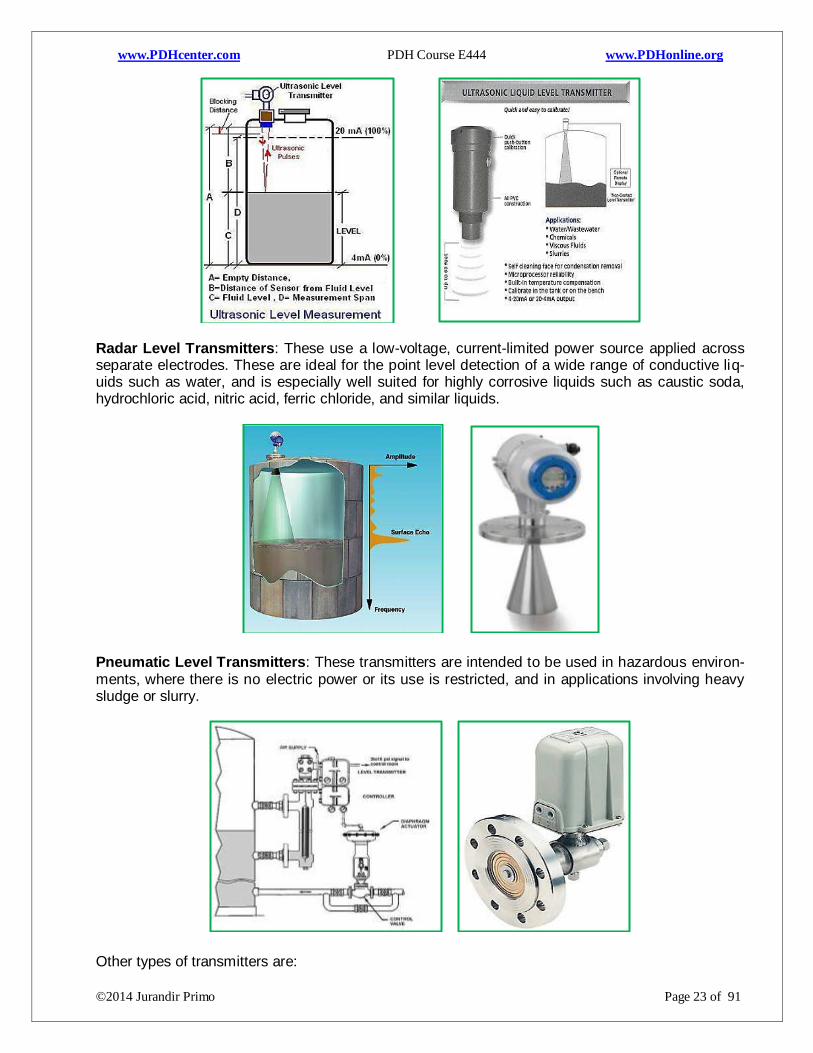
Ultrasonic Level Transmitters: Are used for non-contact level sensing of highly viscous liquids, as well as bulk solids. They are also widely used in water treatment applications for pump control and open channel flow measurement.
Page 24
www.PDHcenter.com PDH Course E444 www.PDHonline.org
©2014 Jurandir Primo Page 23 of 91
Radar Level Transmitters: These use a low-voltage, current-limited power source applied across separate electrodes. These are ideal for the point level detection of a wide range of conductive liq-uids such as water, and is especially well suited for highly corrosive liquids such as caustic soda, hydrochloric acid, nitric acid, ferric chloride, and similar liquids.
Pneumatic Level Transmitters: These transmitters are intended to be used in hazardous environ-ments, where there is no electric power or its use is restricted, and in applications involving heavy sludge or slurry.
Other types of transmitters are:
Page 25
www.PDHcenter.com PDH Course E444 www.PDHonline.org
©2014 Jurandir Primo Page 24 of 91
Electronic pressure transmitters, pneumatic pressure transmitters, submersible pressure transmit-
ters, digital pressure transmitters, wireless pressure transmitters.
Telemetry: Is the reproduction, at a convenient location, of measurements made at remote points. It
is the method of getting information from one point to the other. In general, a telemetering system
consists of:
A measuring instrument which may measure flow, liquid level, pressure, temperature or any
other variable.
A conversion element that converts the measured variable into a proportional air pressure
and electrical quantity.
Indicators: An indicator gives a human operator a convenient way of seeing what the output of the
transmitter is without having to connect test equipment (pressure gauge for 3-15 PSI, ammeter for
4-20 mA) and perform conversion calculations. Moreover, indicators may be located far from their
respective transmitters, providing readouts in locations more convenient than the location of the
transmitter itself.
A numerical Bargraph Indicator, as shown below, may be mounted in the face of a metal panel in-
side of a control room. It is directly wired in series with the same 4-20 mA current signal sent to the
gate actuator. Aside, can be seen a less sophisticated style of Panel Indicator that shows only a
numeric display.
Page 26
www.PDHcenter.com PDH Course E444 www.PDHonline.org
©2014 Jurandir Primo Page 25 of 91
Indicators may also be used in “field” (process) areas to provide direct indication of measured varia-
bles if the transmitter device lacks a human-readable indicator of its own. This Field Indicator,
shown below, also operates directly from the electrical power available in the 4-20 mA loop. The
numerical display of this indicator uses a LCD technology rather than the red-glowing LEDs, in order
to use less electrical power.
Bargraph and Panel Indicator
Field Indicator
Recorders: Sometimes referred to as a chart recorder or a trend recorder, draw a graph of process
variable over time. Recorders usually have indications built into them for showing the instantaneous
value of the instrument signal simultaneously with the historical values, and for this reason are usu-
ally designated as indicating recorders. The Temperature Indicating Recorders, shown below, would
be designated as “TIR” where a circular chart recorder uses a round sheet of paper, rotating slowly
beneath a pen moved side-to-side by a servo-mechanism driven by the instrument signal.
Two more chart recorders are shown, a strip chart recorder on the right and a paperless chart re-
corder on the left. The strip chart recorder uses a scroll of paper drawn slowly past one or more lat-
eral-moving pens, while the paperless recorder does away with paper entirely by plotting graphic
trend lines on a computer screen:
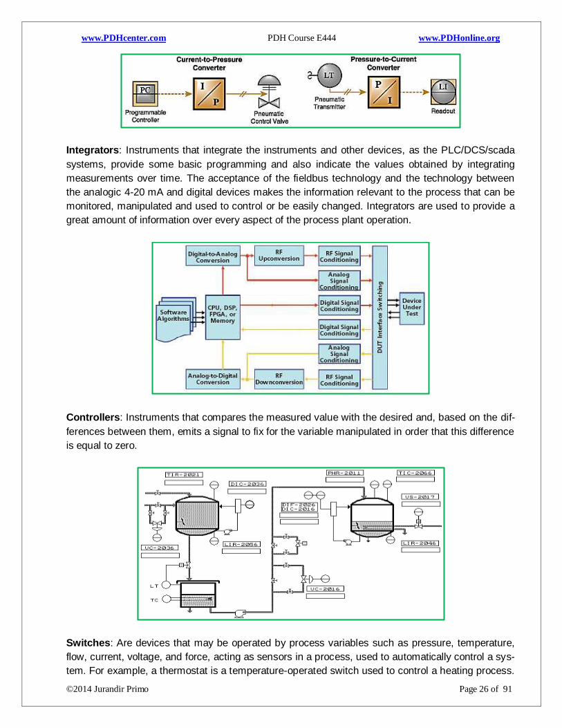
Converters: Instruments, whose function is to receive the information in the form of a sign, change
this form and send it as an output signal, proportional to the input. The typical transducer measure-
ment system block diagram is shown below. The transducer converts the data into an electrical sig-
nal adequate for processing by the circuitry that follows the transducer. The output of the transducer
is an electrical signal representing the measured variable.
Page 27
www.PDHcenter.com PDH Course E444 www.PDHonline.org
©2014 Jurandir Primo Page 26 of 91
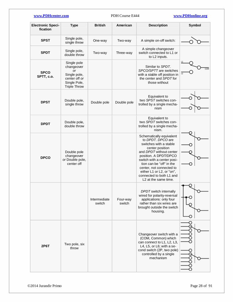
Integrators: Instruments that integrate the instruments and other devices, as the PLC/DCS/scada
systems, provide some basic programming and also indicate the values obtained by integrating
measurements over time. The acceptance of the fieldbus technology and the technology between
the analogic 4-20 mA and digital devices makes the information relevant to the process that can be
monitored, manipulated and used to control or be easily changed. Integrators are used to provide a
great amount of information over every aspect of the process plant operation.
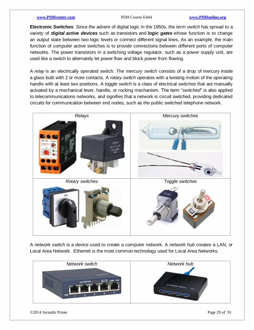
Controllers: Instruments that compares the measured value with the desired and, based on the dif-
ferences between them, emits a signal to fix for the variable manipulated in order that this difference
is equal to zero.
Switches: Are devices that may be operated by process variables such as pressure, temperature,
flow, current, voltage, and force, acting as sensors in a process, used to automatically control a sys-
tem. For example, a thermostat is a temperature-operated switch used to control a heating process.
Page 28
www.PDHcenter.com PDH Course E444 www.PDHonline.org
©2014 Jurandir Primo Page 27 of 91
Relay is a switch that is operated by another electrical circuit; however, large switches may be re-
motely operated by a motor drive mechanism. Some switches are used to isolate electric power
from a system, providing a visible point of isolation that can be padlocked if necessary to prevent
accidental operation of a machine during maintenance, or to prevent electric shock.
The most familiar form of switch is a manually operated electromechanical device with one or more
sets of electrical contacts, which are connected to external circuits. Each set of contacts can be in
one of two states: either "closed or normally closed” (NC) meaning the contacts are closed and
electricity can flow between them, or "open or normally open” (NO), meaning the contacts are
separated and the switch is nonconducting. The mechanism actuating the transition between open
or closed, can be either a "toggle" (flip switch for continuous "on" or "off") or "momentary" (push-for
"on" or push-for "off") type.
Types of Switches: Are designed to respond to any type of mechanical stimulus: for example, vibration
(trembler switch), tilt, air pressure, fluid level (float switch), the turning of a key (key switch), linear or
rotary movement (limit switch or microswitch), or presence of a magnetic field (reed switch). Many
switches are operated automatically by changes in some environmental condition or by motion of ma-
chinery. The limit switch is used, for example, in machine tools to interlock operation with the proper po-
sition of tools. In heating or cooling systems the sail switch ensures that air flow is adequate in a
duct. Pressure switches respond to fluid pressure.
Trembler switch(vibration)
Float switch (fluid level)
Limit switch or Microswitch
Reed switch (magnetic field)
Sail switch (duct air flow)
Pressure switch (fluid pressure)
Contact Terminology: Terms as pole and throw are always used to describe switch contact varia-
tions. The number of "poles" is the number of separate circuits, controlled by a single switch. For
example, a "2-pole" switch has two separate identical sets of contacts controlled by the same
switch. The number of "throws" is the number of separate wiring path choices other than "open"
adapted for each pole of a switch.
The single-throw switch has one pair of contacts, either closed or open. The double-throw switch
has a contact that can be connected to any of other two contacts. The triple-throw has a contact
which can be connected to any of three other contacts, and so on. The table below indicates the
usual types of electro-electronic contacts in industry:
Page 29
www.PDHcenter.com PDH Course E444 www.PDHonline.org
©2014 Jurandir Primo Page 28 of 91
Electronic Speci-fication
Type British
American
Description Symbol
SPST Single pole, single throw
One-way Two-way A simple on-off switch:
SPDT Single pole, double throw
Two-way Three-way A simple changeover
switch connected to L1 or to L2 inputs.
SPCO SPTT, c.o.
Single pole changeover
or Single pole, center off or
Single Pole, Triple Throw
Similar to SPDT. SPCO/SPTT are switches with a stable off position in the center and SPDT for
those without
DPST Double pole, single throw
Double pole Double pole
Equivalent to two SPST switches con-
trolled by a single mecha-nism
DPDT Double pole, double throw
Equivalent to two SPDT switches con-
trolled by a single mecha-nism.
DPCO
Double pole changeover
or Double pole,
center off
Schematically equivalent to DPDT. DPCO are
switches with a stable center position
and DPDT without center position. A DPDT/DPCO switch with a center posi-
tion can be "off" in the center, not connected to either L1 or L2, or "on",
connected to both L1 and L2 at the same time.
Intermediate
switch Four-way
switch
DPDT switch internally
wired for polarity-reversal applications: only four
rather than six wires are brought outside the switch
housing.
2P6T Two pole, six
throw
Changeover switch with a (COM, Common) which
can connect to L1, L2, L3, L4, L5, or L6; with a se-
cond switch (2P, two pole) controlled by a single
mechanism
Page 30
www.PDHcenter.com PDH Course E444 www.PDHonline.org
©2014 Jurandir Primo Page 29 of 91
Electronic Switches: Since the advent of digital logic in the 1950s, the term switch has spread to a
variety of digital active devices such as transistors and logic gates whose function is to change
an output state between two logic levels or connect different signal lines. As an example, the main
function of computer active switches is to provide connections between different ports of computer
networks. The power transistors in a switching voltage regulator, such as a power supply unit, are
used like a switch to alternately let power flow and block power from flowing.
A relay is an electrically operated switch. The mercury switch consists of a drop of mercury inside
a glass bulb with 2 or more contacts. A rotary switch operates with a twisting motion of the operating
handle with at least two positions. A toggle switch is a class of electrical switches that are manually
actuated by a mechanical lever, handle, or rocking mechanism. The term “switched” is also applied
to telecommunications networks, and signifies that a network is circuit switched, providing dedicated
circuits for communication between end nodes, such as the public switched telephone network.
Relays
Mercury switches
Rotary switches
Toggle switches
A network switch is a device used to create a computer network. A network hub creates a LAN, or
Local Area Network. Ethernet is the most common technology used for Local Area Networks.
Network switch
Network hub
Page 31
www.PDHcenter.com PDH Course E444 www.PDHonline.org
©2014 Jurandir Primo Page 30 of 91
4. PROCESS CONTROL INSTRUMENTATION:
Process Control Switches: Process switches generate an on or off output based on a change in
variable phenomenon, commonly used in the process control industry to monitor physical quantities
such as flow, speed, temperature and pressure. Process switches can be characterized by switch-
ing technology used such as electro-mechanical or solid state, available in Normally Open (NO) or
Normally Closed (NC) or both configurations.
A typical example is a pressure switch, when the pressure in a chamber has to be controlled with a
certain value, 50 psi, as an example. The pressure switch controls the range of this temperature
sending a high output when pressure is almost below 50 psi and a low output when pressure reach-
es almost above 50 psi. The range is defined by the process control of the chamber.
The difference between installing transmitters instead of process switches is that transmitters gen-
erally are more expensive. The switch output is typically a voltage free contact, e.g. SPDT Switches
- 120 VAC when on and 0 volts when off. The transmitter has a variable output signal, and 4 to 20
mA current loop is the most common. The most common process switch types are:
Hand switches: To be actuated by a person’s hand motion;
Limit switches: To prevent a machine go on or off, according to process;
Proximity switches: To detect the proximity of an object;
Pressure switches: For measuring low or high pressure (or even a vacuum);
Level switches: For measuring high or low level;
Temperature switches: For measuring high or low temperature;
Flow switches: For measuring high or low flow rate.
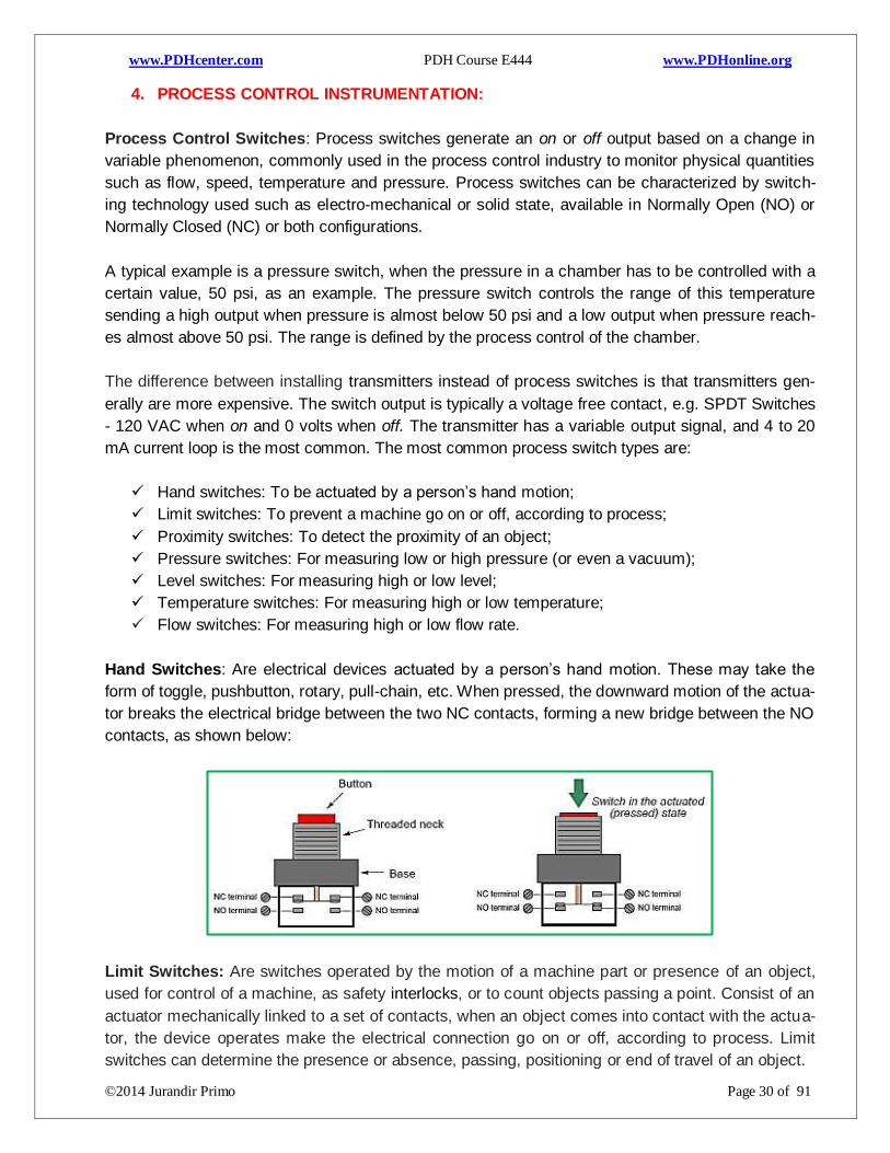
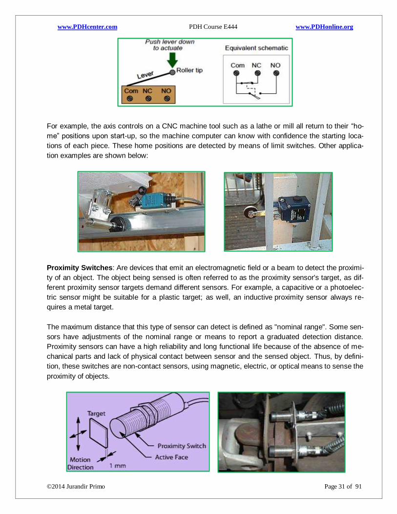
Hand Switches: Are electrical devices actuated by a person’s hand motion. These may take the
form of toggle, pushbutton, rotary, pull-chain, etc. When pressed, the downward motion of the actua-
tor breaks the electrical bridge between the two NC contacts, forming a new bridge between the NO
contacts, as shown below:
Limit Switches: Are switches operated by the motion of a machine part or presence of an object,
used for control of a machine, as safety interlocks, or to count objects passing a point. Consist of an
actuator mechanically linked to a set of contacts, when an object comes into contact with the actua-
tor, the device operates make the electrical connection go on or off, according to process. Limit
switches can determine the presence or absence, passing, positioning or end of travel of an object.
Page 32
www.PDHcenter.com PDH Course E444 www.PDHonline.org
©2014 Jurandir Primo Page 31 of 91
For example, the axis controls on a CNC machine tool such as a lathe or mill all return to their “ho-
me” positions upon start-up, so the machine computer can know with confidence the starting loca-
tions of each piece. These home positions are detected by means of limit switches. Other applica-
tion examples are shown below:
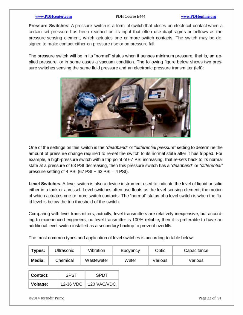
Proximity Switches: Are devices that emit an electromagnetic field or a beam to detect the proximi-
ty of an object. The object being sensed is often referred to as the proximity sensor's target, as dif-
ferent proximity sensor targets demand different sensors. For example, a capacitive or a photoelec-
tric sensor might be suitable for a plastic target; as well, an inductive proximity sensor always re-
quires a metal target.
The maximum distance that this type of sensor can detect is defined as "nominal range". Some sen-
sors have adjustments of the nominal range or means to report a graduated detection distance.
Proximity sensors can have a high reliability and long functional life because of the absence of me-
chanical parts and lack of physical contact between sensor and the sensed object. Thus, by defini-
tion, these switches are non-contact sensors, using magnetic, electric, or optical means to sense the
proximity of objects.
Page 33
www.PDHcenter.com PDH Course E444 www.PDHonline.org
©2014 Jurandir Primo Page 32 of 91
Pressure Switches: A pressure switch is a form of switch that closes an electrical contact when a
certain set pressure has been reached on its input that often use diaphragms or bellows as the
pressure-sensing element, which actuates one or more switch contacts. The switch may be de-
signed to make contact either on pressure rise or on pressure fall.
The pressure switch will be in its “normal” status when it senses minimum pressure, that is, an ap-
plied pressure, or in some cases a vacuum condition. The following figure below shows two pres-
sure switches sensing the same fluid pressure and an electronic pressure transmitter (left):
One of the settings on this switch is the “deadband” or “differential pressure” setting to determine the
amount of pressure change required to re-set the switch to its normal state after it has tripped. For
example, a high-pressure switch with a trip point of 67 PSI increasing, that re-sets back to its normal
state at a pressure of 63 PSI decreasing, then this pressure switch has a “deadband” or “differential”
pressure setting of 4 PSI (67 PSI − 63 PSI = 4 PSI).
Level Switches: A level switch is also a device instrument used to indicate the level of liquid or solid
either in a tank or a vessel. Level switches often use floats as the level-sensing element, the motion
of which actuates one or more switch contacts. The “normal” status of a level switch is when the flu-
id level is below the trip threshold of the switch.
Comparing with level transmitters, actually, level transmitters are relatively inexpensive, but accord-
ing to experienced engineers, no level transmitter is 100% reliable, then it is preferable to have an
additional level switch installed as a secondary backup to prevent overfills.
The most common types and application of level switches is according to table below:
Types: Ultrasonic Vibration Buoyancy Optic Capacitance
Media: Chemical Wastewater Water Various Various
Contact: SPST SPDT
Voltage: 12-36 VDC 120 VAC/VDC
Page 34
www.PDHcenter.com PDH Course E444 www.PDHonline.org
©2014 Jurandir Primo Page 33 of 91
Ultrasonic Level Switches: Are devices that provide reliable high or low-level measurement in a
wide variety of liquids. Installation requires mounting the sensor (threaded or flanged) to the vessel,
connecting the power control wires, and there is no additional set-up or calibration required. Since it
is an electronic instrument with no moving parts, preventive maintenance is limited to an annual
visual inspection. A technician with basic electrical skills (wiring) can service the instrument.
Vibrating Level Switches: Are used in liquids, as well as, in granular and powdery bulk solids con-
sisting of a rod or a fork set for vibrating. When the vibrating probe comes into contact with the me-
dium, the vibration changes and the device outputs a switching command. Vibration rods are easy
to clean and measure reliably regardless of grain size and position. The switching accuracy of vi-
brating level switches with tuning forks is not influenced by material deposits or buildup.
Ultrasonic Level Switches:
Vibrating Level Switches:
Buoyancy Level Switches: Are commonly used to detect reliable liquid level of relatively clean
water and chemical solutions with a 15VA reed switch output, to switch pumps, valves, PLCs relays
and alarms. Media examples may include boric acid and ultrapure water. The submersible polypro-
pylene (PVDF liquid level sensor) is mounted vertically inside the tank, to actuate as a high level
alarm or low level alarm.
Optic Level Switches: Are instruments that work by emitting a beam of infrared light within a prism
and measuring the amount of light received. When the measured fluid reaches the sensor the
amount of emitted light received drops, thus triggering the contacts.
Buoyancy Level Switches
Optic Level Switches
These instruments are suitable for high, low or intermediate level detection in practically any tank,
large or small and the installation is simple over the tank, bottom or side, including water, oil, CO2,
Page 35
www.PDHcenter.com PDH Course E444 www.PDHonline.org
©2014 Jurandir Primo Page 34 of 91
etc. However, optic level switches are not recommended for use in any liquid that crystallizes or
leaves a solid residue.
Capacitance Level Switches: Are instruments that use the RF (radio frequency signals), which is a
technique applied to the capacitance circuit. When the material level changes, inside the contained
space, the electrical capacitance between the electrodes also changes. This change is evaluated
and converted into an output signal, as the rod versions cover a variety of applications, and also
measure aggressive liquids, oils, or powdered and granular bulk materials. The sensor and the wall
of a container (tank or vessel) form the two electrodes of a capacitor.
Paddle-wheel Level Switches: This type of switch uses an electric motor to slowly rotate a metal
paddle inside the process vessel. If solid material rises to the level of the paddle, the material’s bulk
will place a mechanical load on the paddle. A torque-sensitive switch mechanically linked to the mo-
tor actuates when enough torsional effort is detected on the part of the motor. Many switches of this
design have been supplied in the United States under the trade-name Bindicator (so-called because
detects the level of solid material in storage bins), a more primitive variation of the “tuning fork” level
switch, commonly used to detect the level of powder or granular solid materials.
Capacitance Level Switches
Paddle-wheel Level Switches
Temperature Switches: Are instruments used to measure temperature, based upon the tempera-
ture variations in an enclosed space or in an open area. In many switch designs, the temperature
sensing element either rise or drop according to temperature variations, increasing or decreasing
the internal pressure of liquid or gas of the temperature switches. This variation in pressure is used
to actuate a switching mechanism.
Temperature can be measured via a diverse array of sensors. These sensors are induced by tem-
perature realizing changes in physical characteristics of the switches. Six types of temperature
switches are the most common; thermocouples, resistive temperature detectors (RTDs and thermis-
tors), bimetallic devices, liquid filled devices, infrared radiators, and change-of-state devices.
Thermocouples: Consist of two wires composed of dissimilar metals, joined at both ends. One of
the ends is heated, and there is a continuous current which flows in the thermoelectric circuit (See-
beck effect). The junctions can be exposed, grounded or ungrounded. The thermocouple is normally
directly connected to a standard temperature controller. Thermocouples are among the easiest tem-
perature sensors used in science and industry and very cost effective.
Page 36
www.PDHcenter.com PDH Course E444 www.PDHonline.org
©2014 Jurandir Primo Page 35 of 91
Resistive Temperature Detectors (RTD): Is used to measure temperature by correlating the re-
sistance of the RTD element with temperature. The most common metal is Platinum, which is the
RTD element used in a resistance thermometer, besides Nickel alloys, consisting of a wire wound or
thin film element, conforming to DIN standard and with a 0.00385 temperature coefficient. The RTD
is a more accurate temperature sensor and more linear than a thermocouple with a wider tempera-
ture range than a thermistor.
Thermistors: Are temperature sensitive resistors, constructed of semiconductor materials especial-
ly sensitive to temperature. The resistance of a thermistor decreases with increasing temperature,
have small voltage outputs, but not the millivolt outputs of thermocouples. Thermistors are not used
for high temperatures (up to 200 °F) and only for very limited temperature ranges, however, are mo-
re accurate than thermocouples and RTD’s. The disadvantage is the loss of linearity.
Bimetallic Temperature Switches: These instruments consist of a thin rectangular strip formed by
two diverse metals, bonded back to back. When the temperature increases, one metal expands fas-
ter than the other metal, resulting that the bending effect of the metal, activates another switching
temperature device. Thus, the metal strip, shown below, is one of the most commonly used methods
to determine temperature.
Liquid Filled Temperature Switches: Consist of a brass bulb filled with a chemical fluid (some-
times gas) including a small tube which lifts up the bulb to a pressure sensing mechanism with bel-
lows, a bourdon tube or a diaphragm. When the temperature inside the bulb increases, it causes the
liquid or gas inside the bulb to spread out. This expansion increases the pressure inside the bulb,
resulting in the activation of the pressure switch connected to the bulb.
Bimetallic Temperature Switches
Liquid Filled Temperature Switches
Page 37
www.PDHcenter.com PDH Course E444 www.PDHonline.org
©2014 Jurandir Primo Page 36 of 91
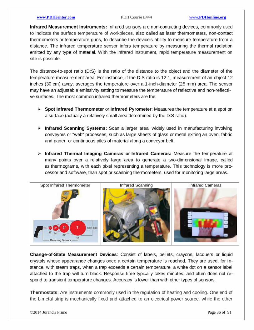
Infrared Measurement Instruments: Infrared sensors are non-contacting devices, commonly used
to indicate the surface temperature of workpieces, also called as laser thermometers, non-contact
thermometers or temperature guns, to describe the device's ability to measure temperature from a
distance. The infrared temperature sensor infers temperature by measuring the thermal radiation
emitted by any type of material. With the infrared instrument, rapid temperature measurement on
site is possible.
The distance-to-spot ratio (D:S) is the ratio of the distance to the object and the diameter of the
temperature measurement area. For instance, if the D:S ratio is 12:1, measurement of an object 12
inches (30 cm) away, averages the temperature over a 1-inch-diameter (25 mm) area. The sensor
may have an adjustable emissivity setting to measure the temperature of reflective and non-reflecti-
ve surfaces. The most common infrared thermometers are the:
Spot Infrared Thermometer or Infrared Pyrometer: Measures the temperature at a spot on
a surface (actually a relatively small area determined by the D:S ratio).
Infrared Scanning Systems: Scan a larger area, widely used in manufacturing involving
conveyors or "web" processes, such as large sheets of glass or metal exiting an oven, fabric
and paper, or continuous piles of material along a conveyor belt.
Infrared Thermal Imaging Cameras or Infrared Cameras: Measure the temperature at
many points over a relatively large area to generate a two-dimensional image, called
as thermograms, with each pixel representing a temperature. This technology is more pro-
cessor and software, than spot or scanning thermometers, used for monitoring large areas.
Spot Infrared Thermometer
Infrared Scanning
Infrared Cameras
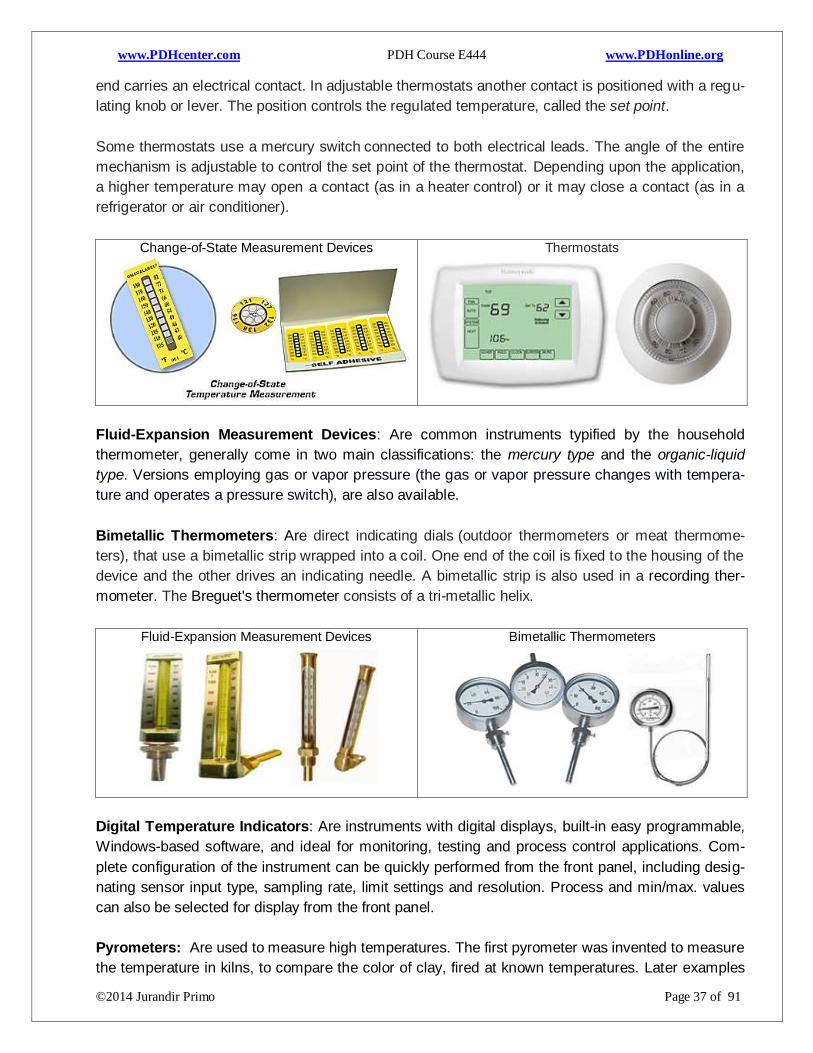
Change-of-State Measurement Devices: Consist of labels, pellets, crayons, lacquers or liquid
crystals whose appearance changes once a certain temperature is reached. They are used, for in-
stance, with steam traps, when a trap exceeds a certain temperature, a white dot on a sensor label
attached to the trap will turn black. Response time typically takes minutes, and often does not re-
spond to transient temperature changes. Accuracy is lower than with other types of sensors.
Thermostats: Are instruments commonly used in the regulation of heating and cooling. One end of
the bimetal strip is mechanically fixed and attached to an electrical power source, while the other
Page 38
www.PDHcenter.com PDH Course E444 www.PDHonline.org
©2014 Jurandir Primo Page 37 of 91
end carries an electrical contact. In adjustable thermostats another contact is positioned with a regu-
lating knob or lever. The position controls the regulated temperature, called the set point.
Some thermostats use a mercury switch connected to both electrical leads. The angle of the entire
mechanism is adjustable to control the set point of the thermostat. Depending upon the application,
a higher temperature may open a contact (as in a heater control) or it may close a contact (as in a
refrigerator or air conditioner).
Change-of-State Measurement Devices
Thermostats
Fluid-Expansion Measurement Devices: Are common instruments typified by the household
thermometer, generally come in two main classifications: the mercury type and the organic-liquid
type. Versions employing gas or vapor pressure (the gas or vapor pressure changes with tempera-
ture and operates a pressure switch), are also available.
Bimetallic Thermometers: Are direct indicating dials (outdoor thermometers or meat thermome-
ters), that use a bimetallic strip wrapped into a coil. One end of the coil is fixed to the housing of the
device and the other drives an indicating needle. A bimetallic strip is also used in a recording ther-
mometer. The Breguet's thermometer consists of a tri-metallic helix.
Fluid-Expansion Measurement Devices
Bimetallic Thermometers
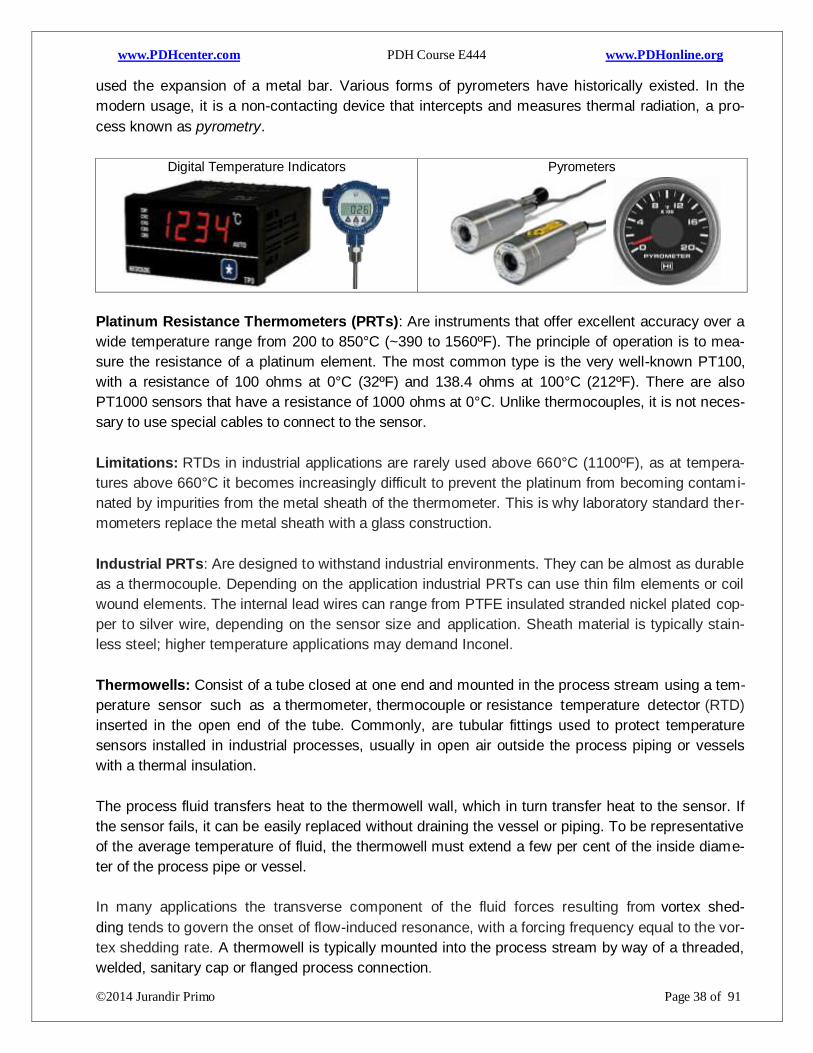
Digital Temperature Indicators: Are instruments with digital displays, built-in easy programmable,
Windows-based software, and ideal for monitoring, testing and process control applications. Com-
plete configuration of the instrument can be quickly performed from the front panel, including desig-
nating sensor input type, sampling rate, limit settings and resolution. Process and min/max. values
can also be selected for display from the front panel.
Pyrometers: Are used to measure high temperatures. The first pyrometer was invented to measure
the temperature in kilns, to compare the color of clay, fired at known temperatures. Later examples
Page 39
www.PDHcenter.com PDH Course E444 www.PDHonline.org
©2014 Jurandir Primo Page 38 of 91
used the expansion of a metal bar. Various forms of pyrometers have historically existed. In the
modern usage, it is a non-contacting device that intercepts and measures thermal radiation, a pro-
cess known as pyrometry.
Digital Temperature Indicators
Pyrometers
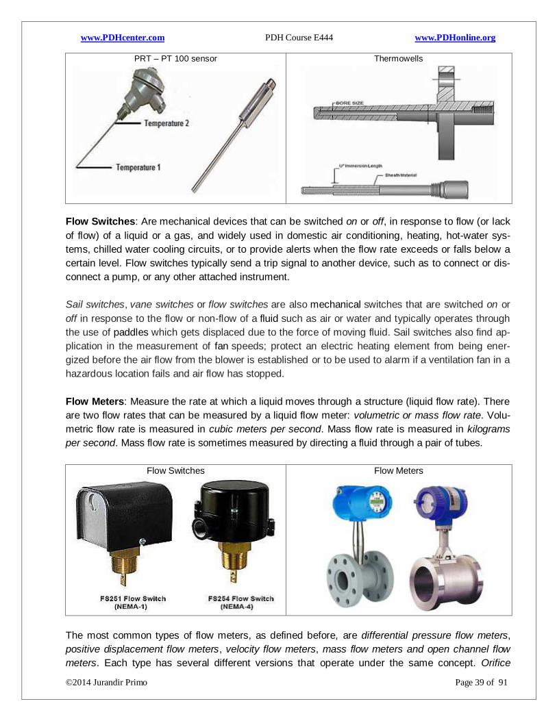
Platinum Resistance Thermometers (PRTs): Are instruments that offer excellent accuracy over a
wide temperature range from 200 to 850°C (~390 to 1560ºF). The principle of operation is to mea-
sure the resistance of a platinum element. The most common type is the very well-known PT100,
with a resistance of 100 ohms at 0°C (32ºF) and 138.4 ohms at 100°C (212ºF). There are also
PT1000 sensors that have a resistance of 1000 ohms at 0°C. Unlike thermocouples, it is not neces-
sary to use special cables to connect to the sensor.
Limitations: RTDs in industrial applications are rarely used above 660°C (1100ºF), as at tempera-
tures above 660°C it becomes increasingly difficult to prevent the platinum from becoming contami-
nated by impurities from the metal sheath of the thermometer. This is why laboratory standard ther-
mometers replace the metal sheath with a glass construction.
Industrial PRTs: Are designed to withstand industrial environments. They can be almost as durable
as a thermocouple. Depending on the application industrial PRTs can use thin film elements or coil
wound elements. The internal lead wires can range from PTFE insulated stranded nickel plated cop-
per to silver wire, depending on the sensor size and application. Sheath material is typically stain-
less steel; higher temperature applications may demand Inconel.
Thermowells: Consist of a tube closed at one end and mounted in the process stream using a tem-
perature sensor such as a thermometer, thermocouple or resistance temperature detector (RTD)
inserted in the open end of the tube. Commonly, are tubular fittings used to protect temperature
sensors installed in industrial processes, usually in open air outside the process piping or vessels
with a thermal insulation.
The process fluid transfers heat to the thermowell wall, which in turn transfer heat to the sensor. If
the sensor fails, it can be easily replaced without draining the vessel or piping. To be representative
of the average temperature of fluid, the thermowell must extend a few per cent of the inside diame-
ter of the process pipe or vessel.
In many applications the transverse component of the fluid forces resulting from vortex shed-
ding tends to govern the onset of flow-induced resonance, with a forcing frequency equal to the vor-
tex shedding rate. A thermowell is typically mounted into the process stream by way of a threaded,
welded, sanitary cap or flanged process connection.
Page 40
www.PDHcenter.com PDH Course E444 www.PDHonline.org
©2014 Jurandir Primo Page 39 of 91
PRT – PT 100 sensor
Thermowells
Flow Switches: Are mechanical devices that can be switched on or off, in response to flow (or lack
of flow) of a liquid or a gas, and widely used in domestic air conditioning, heating, hot-water sys-
tems, chilled water cooling circuits, or to provide alerts when the flow rate exceeds or falls below a
certain level. Flow switches typically send a trip signal to another device, such as to connect or dis-
connect a pump, or any other attached instrument.
Sail switches, vane switches or flow switches are also mechanical switches that are switched on or
off in response to the flow or non-flow of a fluid such as air or water and typically operates through
the use of paddles which gets displaced due to the force of moving fluid. Sail switches also find ap-
plication in the measurement of fan speeds; protect an electric heating element from being ener-
gized before the air flow from the blower is established or to be used to alarm if a ventilation fan in a
hazardous location fails and air flow has stopped.
Flow Meters: Measure the rate at which a liquid moves through a structure (liquid flow rate). There
are two flow rates that can be measured by a liquid flow meter: volumetric or mass flow rate. Volu-
metric flow rate is measured in cubic meters per second. Mass flow rate is measured in kilograms
per second. Mass flow rate is sometimes measured by directing a fluid through a pair of tubes.
Flow Switches
Flow Meters
The most common types of flow meters, as defined before, are differential pressure flow meters,
positive displacement flow meters, velocity flow meters, mass flow meters and open channel flow
meters. Each type has several different versions that operate under the same concept. Orifice
Page 41
www.PDHcenter.com PDH Course E444 www.PDHonline.org
©2014 Jurandir Primo Page 40 of 91
plates, venturi tubes and flow tubes are all examples of differential pressure flow meters. Recipro-
cating pistons and rotary vanes are both examples of positive displacement flow meters. Turbines
and Doppler meters are both common types of velocity flow meters. Coriolis and thermal are both
mass flow meters.
Velocimeters: Flow meters are also called velocimeters when are used to measure the velocity of
fluids flowing through them. The laser-based interferometry is often used for air flow measurement.
The Doppler-based methods are used for flow measurement. Hall effect sensors may also be used,
on a flapper valve, or vane, to sense the position of the vane, as displaced by fluid flow.
Ultrasonic Flow Meters: Consist of a pair of transmitters fitted to the termination points on a tube.
A short burst of sound travels through the tube, and is measured by the flow meter as it passes
through the liquid in the tube. Using a transmitter-receiver method is useful for testing the way a fluid
flows through another medium, such as a metal or plastic pipe. Generally, ultrasonic flow meters
test the velocity in a liquid (particularly useful in waste water management, where testing for parti-
cles and solids in water is a matter of public health).
Velocimeters
Ultrasonic Flow Meters
Flow Sensors: Are devices for sensing the rate of fluid flow. Typically a flow sensor is the sensing
element used in a flow meter, or flow logger, to record the flow of fluids. Absolute accuracy of a
measurement requires functionality for calibration of all sensors. There are various kinds of flow
sensors, including some that have a vane pushed by the fluid to drive a rotary potentiometer, or sim-
ilar devices. Other flow sensors are based on sensors which measure the transfer of heat caused by
the moving medium. This principle is common for micro-sensors to measure flow.
Gas Flow Meters: Are used to measure the flow of the moving gas. There are several analyzers
and sensors used to detect the quantity of gas flowing in the given area under specific conditions. It
is used to measure the temperature, pressure and velocity of the gas. This is usually done with a
help of flow sensors which also include detectors, switches, meters and flow controllers.
At times, the measurement of gas flow becomes so vital that a wrong assessment may lead to dis-
aster. There are several types of gas flow meters available, such as rotary meters, turbine meters,
orifice meters, ultrasonic meters and diaphragm meters. Another popular use of gas flow meters is
in welding machines, where the meter is enclosed in plastic or glass cylinder.
Page 42
www.PDHcenter.com PDH Course E444 www.PDHonline.org
©2014 Jurandir Primo Page 41 of 91
Propane is mostly used for this purpose and it is very essential to measure the amount of gas that
runs through the gas pipe into the house. The gas flow meter is put on these gas pipes to measure
the temperature as well as the quantity of the gas flowing through the pipes. These meters also help
the gas companies to ascertain the quantity of gas being consumed.
Flow Sensors
Gas Flow Meters
Load Cells: Are used in several types of measuring instruments, commonly used as weight-based
level instruments to directly measuring the weight of a vessel or a support structure, through trans-
ducers used to convert a force into an electrical signal. This conversion is in two stages. Through a
mechanical arrangement, the force being sensed deforms a strain gauge. The strain gauges mea-
sure the deformation (strain) as an electrical signal, changing the electrical resistance of the wire.
A load cell usually consists of four strain gauges called Wheatstone bridge configuration, with one
strain gauge (quarter bridge), or two strain gauges (half bridge), are available. The electrical signal
output is typically in the order of a few millivolts and requires amplification by an instrumentation am-
plifier before it can be used. The various types of load cells are; Hydraulic load cells, Pneumatic lo-
ad cells and Strain-gauge load cells. Hydraulic load cells, Pneumatic load cells and Strain-gauge lo-
ad cells, Piezoelectric Load Cells, Vibrating Wire Load Cells, S-beam Load Cells, Capacitive Load
Cells and Button Load Cells.
Hydraulic Load Cells: Are devices that use conventional piston and cylinder arrangement, placed
in a thin elastic diaphragm, and the load cell is completely filled with oil. When a load is applied on
the piston, the movement of the piston and the diaphragm arrangement result in an increase of oil
pressure which in turn produces a change in the pressure on a Bourdon tube connected with the
load cells. Typical hydraulic load cell applications include tanks, bins and hoppers weighing.
Pneumatic Load Cells: Use air pressure applied to one end of the diaphragm and automatically
regulates the balancing pressure, when air escapes through the nozzle placed at the bottom of the
load cell. A pressure gauge is attached to measure the pressure inside the cell. The deflection of the
diaphragm affects the airflow through the nozzle, as well as, the pressure inside the chamber.
Strain-gauge Load Cells: Work with the principle that the strain gauge (a planar resistor) de-
forms/stretches/contracts when the material of the load cells deforms appropriately. These values
are extremely small and are relational to the stress and/or strain that the material load cell is under-
going at the time. The change in resistance of the strain gauge provides an electrical value change
that is calibrated to the load placed on the load cell.
Page 43
www.PDHcenter.com PDH Course E444 www.PDHonline.org
©2014 Jurandir Primo Page 42 of 91
Hydraulic Load Cell:
Pneumatic Load Cell:
Strain-gage Load Cell:
Piezoelectric Load Cells: These electronic instruments are used to measure strain and forces in-
side machine parts. The sensor is installed into the industry-standard 8-mm bore which runs per-
pendicular to the direction of the force to be measured. The sensor can be fitted in a recessed way
in deeper bores.
Vibrating Wire Load Cells: These types of load instruments are ideally suited for measuring loads
in rock bolts, cable anchors and tendons, structural beams, piles, loads between tunnel supports
and loads in pull-out tests on trial anchors. Consist of a high strength steel alloy cylindrical housing
with three to six vibrating wire gauges for measuring the compression of the cylinder under load.
The readings are averaged minimizing the effects of eccentric or uneven loadings.
S-beam Load Cells: These load cells use the shear principles to amplify the effects of the load on
strain gauges within the load cell and can be used in tension or compression. Typical uses are in
test machines, platforms, conveyors, overhead track scales and for general in-line load measure-
ment applications.
Capacitive Load Cells: Is based on a capacitive measurement principle where a non-contacting
ceramic sensor is mounted inside the load cell body and can tolerate shocks, torsion, and very high
overloads and side loads. The capacitance changes, as the signal from the non-contacting sensor is
directly converted when the load presses two plates close together.
Button Load Cells: Are small sensors that measure compression loads, used in applications that
require a thin form factor. The bottom of the load cell is bolted, and force applied to the button on
the top. By loading only the button, which is slightly rounded, the load cell is less sensitive to errors,
resulting the load may not be pushing down exactly straight on the load cell.
Piezoelectric Load Cells
Vibrating Wire Load Cells
S-beam Load Cells
Capacitive Load Cells
Page 44
www.PDHcenter.com PDH Course E444 www.PDHonline.org
©2014 Jurandir Primo Page 43 of 91
5. CONDUCTIVITY & ANALYTICAL INSTRUMENTATION:
Conductivity: Is the measure of the ease at which an electric charge or heat can pass through a
material. Electrical conductivity is when a material will easily allow electricity to travel through it. A
conductor is a material that gives very little resistance to the flow of an electric current or thermal
energy. Materials are classified as metals, semiconductors, and insulators. Metals are the most
conductive in nature, and insulators (ceramics, wood, plastics) the least conductive.
Thermal Conductivity: Is the measure of the ease at which thermal energy (heat for most purpos-
es) can move through a material. Some materials like metals allow heat to travel through them quite
quickly. For example, metal has a higher heat transferability, or thermal conductivity than wood. Ce-
ramics, and polymers are usually good insulators, however, polymers usually have a very low melt-
ing temperature.
Conductivity in Water: Is the measurement of the electrical conductivity of water, when is passed
an electrical current. Conductivity in water is affected by the presence of inorganic dissolved solids
such as chloride, nitrate, sulfate, and phosphate anions (ions that carry a negative charge) or sodi-
um, magnesium, calcium, iron, and aluminum cations (ions that carry a positive charge).
Organic compounds like oil, phenol, alcohol, and sugar do not conduct electrical current very well
and therefore, have a low conductivity when in water. Conductivity is also affected by temperature:
the warmer the water, the higher the conductivity. For this reason, conductivity is reported as con-
ductivity at 25 degrees Celsius (25 C).
Conductivity in Metals: Is the measurement of the electrical conductivity of a metal object, when is
passed an electrical current. When a voltage is applied across two points of a liquid solution, nega-
tive ions will drift toward the positive pole (anode) and positive ions will drift toward the negative pole
(cathode). Negative ions are sometimes called anions (attracted to the anode), while positive ions
are sometimes called cations (attracted to the cathode).
Conductivity in Gases: Is much the same, ions are the charge carriers. However, with gases at
room temperature, ionic activity is virtually nonexistent. A gas must be superheated into a plasma
state before substantial ions exist which can support an electric current. However, the thermal con-
ductivity of a gas is a specific physical quantity. Then, when a gas mixture is composed of two com-
ponents, the concentration of each of the components through its property can be known.
Conductivity Measurement: Is generally measured with a probe and a meter. Voltage is applied
between two electrodes in a probe immersed in a sample water. The drop in voltage caused by the
resistance of the water is used to calculate the conductivity.
The meter converts the probe measurement to micromhos per centimeter (µmhos/cm) or
microsiemens per centimeter (µs/cm) and displays the result for the user. Distilled water has con-
ductivity in the range of 0.5 to 3 µmhos/cm. Conductivity of rivers in the United States generally
ranges from 50 to 1500 µmhos/cm.
Page 45
www.PDHcenter.com PDH Course E444 www.PDHonline.org
©2014 Jurandir Primo Page 44 of 91
Electrolyte: Is any substance that enhances electrical conductivity when dissolved in water. This
enhancement of conductivity occurs due to the molecules of the electrolyte separate into positive
and negative ions, and serve as electrical charge carriers. If the electrolyte is an ionically-bonded
compound, (example, table salt), the ions forming that compound naturally separate in solution, and
this separation is called dissociation.
If the electrolyte is a covalently-bonded compound, (example hydrogen chloride), the separation of
those molecules into positive and negative ions is called ionization. Both dissociation and ionization
refer to the separation of formerly joined atoms upon entering a solution. The difference between
these terms is the type of substance that splits: “dissociation” refers to the division of ionic com-
pounds (table salt), while “ionization” refers to covalent-bonded (molecular) compounds such as HCl
which are not ionic in their pure state.
The most primitive form of conductivity sensor (or a conductivity cell) consists of two metal elec-
trodes inserted in the solution, connected to a circuit designed to measure conductance, the recip-
rocal of resistance. Two-electrode conductivity cells are not very practical in real applications, be-
cause mineral and metal ions attracted to the electrodes tend to “foul” the electrodes over time form-
ing solid, insulating barriers on the electrodes.
pH Measurement: Is the measurement of the hydrogen ion activity in a liquid solution. The pH is al-
so a significant factor in the corrosion of metal pipes and vessels carrying aqueous (water-based)
solutions. Food processing, water treatment, pharmaceutical production, steam generation (thermal
power plants), and alcohol manufacturing are just some of the industries making extensive use of
pH measurement (and control).
The measurement of pH can be divided broadly into two methods: Method of electro-electronic
measurement and measurement method for color comparison. The industrial area, employs the
method of electrical measurement due to its ease of handling and ease in instrumentation.
Electronic Meter: Is a device used for measuring the pH (acidity or alkalinity) of a liquid
(though special probes, used to measure the pH of semi-solid substances) and consists of a
Page 46
www.PDHcenter.com PDH Course E444 www.PDHonline.org
©2014 Jurandir Primo Page 45 of 91
special measuring probe (glass electrode) connected to an electronic meter that measures
and displays the pH reading. The probe is a rod type usually made up of glass. At the bottom
of the probe there is a bulb that also contains a sensor. The probe is dipped to measure the
pH of a solution.
Glass Electrode Measuring Probe: The glass electrode probe contains a liquid inside that
is standard solution with a pH equal to 7 and the liquid medium uses potassium chloride
(KCL) for the differential electrode. The KCL is used because it presents the smallest differ-
ence of electrical potential between the liquids measured.
Colorimetric Measurement: One of the simplest ways to measure the pH of a solution is by
color. Some chemical compounds dissolved in an aqueous solution, change their colors if
the pH value of that solution falls within a certain range. The colorimetric method employs
the use of complex orga- nic dyes which change to distinctive colors through a specific pH
range. These dyes are known as indicators; with a pH range from 4.0 to 8.4 can be reached.
The main dyes are:
pH Meters: Range from simple and inexpensive pen-like devices to complex and expensive labora-
tory instruments with computer interfaces and several inputs for indicator and temperature measure-
ments. There are also holographic pH sensors, which allow the measurement pH colorimetrically.
pH - Colorimetric and Electrometric: As a general rule, electrometric methods are more precise
than colorimetric methods, simply because it is easier to measure a change in voltage, current,
and/or electrical resistance than it is to see some color vs. a reference. A pH meter using a glass
electrode is not the "best" method. Electrical conductivity is better because electrical conductivity
can be measured with higher accuracy.
pH – Electronic Digital Meter:
Glass Electrode Measuring:
pH –Pen-like Devices:
Page 47
www.PDHcenter.com PDH Course E444 www.PDHonline.org
©2014 Jurandir Primo Page 46 of 91
Non-Dispersive Analysis: Industrial non-dispersive analyzers typically use either infrared or ultra-
violet light sources, because most substances of interest absorb wavelengths in those regions ra-
ther than in the visible light spectrum. Non-dispersive analyzers employ the principle of spectro-
graphic absorption to measure how much of a particular substance exists within a sample.
Gas analysis is the more common application of non-dispersive spectroscopy in industry, as op-
posed to liquid analysis. Non-dispersive spectroscopy using infrared light is usually abbreviated
NDIR, while non-dispersive spectroscopy using ultraviolet light is abbreviated NDUV and non-
dispersive spectroscopy using visible light is abbreviated NDVIS. Historically, NDIR is more preva-
lent of these three technologies.
Single-beam Analyzer: Is the simplest style of non-dispersive analyzer that uses a single light sou-
rce, shining continuously through a single gas cell, and eventually falling on a small thermopile (con-
verting the received infrared light into heat, and then into a voltage signal). An example would be the
measurement of carbon dioxide (CO2) concentration in the exhaust gas of a combustion furnace;
however, most of the gases exiting the furnace do not absorb infrared light as Nitrogen. Carbon
monoxide (CO), water vapor (H2O), and sulfur dioxide (SO2) absorb infrared light, and are all nor-
mally present in the exhaust gas of a furnace.
Gas Filter Correlation (GFC): Is called positive filtering in the field of spectroscopy using filter cells
to eliminate wavelengths associated with interfering gases where the analyzer filters out all wave-
lengths associated with all interfering species. The gas filter analyzers use a single gas cell rather
than dual cells (sample and reference), through which a light beam of alternating spectrum is
passed. A rotating filter wheel creates this alternating spectrum, as seen below:
Page 48
www.PDHcenter.com PDH Course E444 www.PDHonline.org
©2014 Jurandir Primo Page 47 of 91
Safety Gas Analyzers: Measure the concentration of specific substances for the purpose of meas-
uring and/or controlling those concentrations in a process stream. Safety analyzers detect the pres-
ence of dangerous concentrations of specific substances to personnel threats to life or health. There
are no ends to the different types of process analyzers to meet the needs of process industries, but
applications, sometimes, rather restricted to those substances known to human health hazards.
There are analysers that measure a wide range of gases, wall mounted or highly portable to be suit-
able for an extensive range of geoscience applications. Fast response high-precision analyzers are
widely used to measure gas emissions and ecosystem fluxes using eddy covariance methods (at-
mospheric measurement technique to measure and calculate air turbulent fluxes, when used to-
gether with sonic anemometers.
Safety gas analyzers are made for many applications, such as, motor vehicles, utilities, energy, en-
vironmental, research, and petroleum industries. Environmental and gas analyzers include diode
laser analyzers, oxygen analyzers, infrared gas analyzers, stack gas analyzers, dust monitors, pro-
cess gas chromatographs, gas density analyzers, clean room gas monitors to bulk analyzers that
measure over 270 different gases; several can operate in hazardous environments. The most used
industrial gas analyzers are:
Katharometers: Are thermal conductivity analyzers (TCD) for measuring levels of some gas in a
binary or pseudo-binary mixture, commonly used in gas chromatography. For example, air is com-
posed of many gases; therefore hydrogen is a pseudo-binary mixture, measured with a
katharometer. Hydrogen, helium, dissociated ammonia, sulphur hexafluoride and noble gases, such
as, krypton and xenon are all well suited to this technique.
Infrared Gas Analyzers: Measure gas traces by determining the absorption of an emit-
ted infrared light source. Modern analyzers use the Non-dispersive Infrared Technology (NDIR) to
detect a certain gas by detecting the absorption of infrared wavelengths, characteristic of that gas.
By optically filtering the energy, the radiation spectrum is limited according to the absorption band of
the gas being measured.
Stack Gas Analyzers: Consist also of a Non-dispersive Infrared (NDIR) gas analyzer using a high-
ly sensitive and stable double beam system and a zirconia or paramagnetic oxygen analyzer to sim-
ultaneously measure up to 5 components, NOx, SO2, CO2, CO and O2, commonly used for measur-
ing and monitoring emissions from various boilers and waste incinerators.
Katharometers
Infrared Gas Analyzers
Stack Gas Analyzers
Page 49
www.PDHcenter.com PDH Course E444 www.PDHonline.org
©2014 Jurandir Primo Page 48 of 91
Upper/Lower Explosive Sensors: Measure the maximum or minimum concentration of flammable
gases in air capable of igniting. These sensors are specially designed to detect the dangerous pres-
ence of combustible gases, also called “UEL or LEL sensors”. Gases and vapors are not the only
substances with potential to explode in sufficient concentrations. Certain dusts (such as grain) and
fibers (such as cotton) may also present explosion hazards, when in sufficient quantity. However,
the majority of analytical technologies only function with gases and vapors (Class I), not dusts or
fibers (Class II and Class III, respectively).
Hydrogen Sulfide (H2S): Is a highly toxic gas that has a pungent “rotten eggs” odor at low concen-
trations, but no visible color. Seems odorless, and at higher concentrations, this gas acts as a nerve
agent to de-sensitize human smell, so that it causes a paralytic effect, extending to the more im-
portant bodily functions such as breathing, and rapid loss of consciousness and asphyxiation. The
below photograph of a safety chart shows just how toxic hydrogen sulfide gas is:
Note: Note how concentrations in the parts per million are hazardous, and how little H2S concentration is
required to paralyze one’s sense of smell. Hydrogen sulfide also happens to be flammable, its LEL value in air being 4.3%. However, the toxic properties of H2S are more concerning when released into the atmosphere.
Page 50
www.PDHcenter.com PDH Course E444 www.PDHonline.org
©2014 Jurandir Primo Page 49 of 91
Carbon Monoxide (CO): Is a colorless, odorless, and toxic gas principally generated by the incom-
plete combustion of carbon-based fuels. At significant concentrations of carbon monoxide gas in air,
the hemoglobin in your blood latches on to CO molecules instead of oxygen (O2) molecules, and
remains bound to the hemoglobin, preventing it from transporting oxygen. The result is that your
blood rapidly loses its oxygen-carrying capacity, and your body asphyxiates from within.
Like hydrogen sulfide, carbon monoxide is also flammable (LEL = 4%), but its toxic properties are
generally the larger concern when released into the atmosphere. Carbon monoxide is not to be con-
fused with carbon dioxide (CO2) gas, which is almost completely inert to the human body. Carbon
dioxide is principally produced by complete combustion of carbon based fuels. Its only safety hazard
potential is the capacity to displace breathable air in an enclosed area if rapidly released in large
volumes.
Chlorine (Cl2): Is a strong-odored, toxic gas used as a biological disinfectant, bleaching agent, and
as an oxidizer in many industrial processes. Colorless in low concentrations, it may appear green in
color when mixed in very high concentrations with air. Water and wastewater treatment operations
frequently use chlorine for disinfection of water. Pulp mills use either chlorine or chlorine compounds
as a bleaching agent to whiten the wood pulp process.
Chlorine is highly reactive, presenting a distinct hazard to mucous membranes (eyes, nose, throat,
lungs) by creating hypochlorous acid (HOCl) and hydrochloric acid (HCl) upon contact with water:
Cl2 + H2O → HOCl + HCl. The following table correlates levels of chlorine gas concentration with
degree of hazard. The unit of measurement for chlorine concentration in air – parts per million (ppm)
equivalent to just 0.0001 percent:
Page 51
www.PDHcenter.com PDH Course E444 www.PDHonline.org
©2014 Jurandir Primo Page 50 of 91
6. CONTROL VALVES & INSTRUMENTATION:
Control Valves: Regulate the rate of fluid flow as the position of the valve plug or disk is changed
by force from actuators or signals of positioners, commonly used to control conditions such
as flow, pressure, temperature, and liquid level by fully or partially opening or closing. Automatic
control valves actuate in response to signals received from controllers that compare a "setpoint" to a
"process variable", whose values are provided by sensors that monitor the condition changes.
Actuators: The opening or closing of control valves is usually done automatically by electric,
hydraulic or pneumatic actuators.
Positioners: Are devices used to control the opening or closing of actuators based on either
electric or pneumatic control signals.
These control signals, are traditionally based on 3 – 15 psi (0.2 - 1.0 bar), or the well-known electro-
electronic 4 - 20 mA signals for industry, 0 - 10V for HVAC systems and the introduction of smart
systems, or either analogic or digital protocols, such as, HART, Fieldbus Foundation and Profibus,
the most common protocols. The following summary describes some special control valve styles:
Relief and Safety Valves: These types of valves have the main function to prevent process equip-
ment damage by relieving excess pressure in a fluid system. The main difference between a relief
valve and a safety valve is the extent of opening at the setpoint pressure, as described below:
Relief Valves: Open gradually, when the inlet pressure increases above the defined process
setpoint, and open only the necessary to relieve the over-pressure condition. Relief Valves
are typically used for incompressible fluids such as water or oil.
Safety Valves: Open immediately, when the defined pressure setpoint is reached, and stay
fully open until the process pressure drops below a reset point. The reset pressure, normally,
is lower than the actuating pressure setpoint. Safety Valves are typically used for compressi-
ble fluids such as steam or other gases.
The difference between the actuating pressure setpoint and the pressure of resetting is called blow-
down, expressed as a percentage of the actuating pressure setpoint. The defined pressure setpoint
is adjusted by turning the adjusting nuts on top of the valve yoke to increase or decrease the spring
compression in both Relief and Safety valves, as can be seen in the pictures below:
Pilot-Operated Valves: Are designed to keep the pressure in balance, through a small passage at
the top of a piston connected to the stem, and are typically solenoid-operated valves, with the ener-
gizing signal originating from pressure measuring systems. When the small valve pilot opens, the
pressure is relieved, keeping the balance of the system.
Note: Safety valves can often be distinguished by the presence of an external lever at the top of the
valve body, which is used as an operational check. Both Safety and Relief Valve open by spring
compression, when the system pressure overcomes the spring characteristics.
Page 52
www.PDHcenter.com PDH Course E444 www.PDHonline.org
©2014 Jurandir Primo Page 51 of 91
Relief Valves Safety Valves
Solenoid Valves: The solenoid is an integrated device, which actuates either a pneumatic or a hy-
draulic valve. The solenoid is an electromechanical coil wound into a tightly packed helix, a specific
type of relay that operates as an electrical switch. The term solenoid refers specifically to a magnet
designed to produce a uniform electric field in a volume of space. The term solenoid may also refer
to a variety of transducer devices that convert energy into linear motion.
Solenoid Valves Parts: Are the most frequent devices used for control in fluid flow, to shut off, re-
lease, dose, distribute or mix fluids. The solenoid valve has two main parts: the solenoid and the
valve. The solenoid converts electrical energy into mechanical energy which, in turn, opens or clos-
es the valve mechanically. In the case of a two-port valve the flow is switched on or off; the three-
port valve, the outflow is switched between the two outlet ports. Multiple solenoid valves can be
placed together on a manifold.
Page 53
www.PDHcenter.com PDH Course E444 www.PDHonline.org
©2014 Jurandir Primo Page 52 of 91
Rotary Solenoid Valves: The rotary solenoid is a round design electromechanical device, used to
rotate a ratcheting mechanism when power is applied, suited in industrial applications to convert
linear force into rotary motion, or rotary snap-switch automation in electromechanical controls, which
range is commonly 25/35/50/60/75 & 100mm diameter. The solenoid coils are 3.5 VDC to 462 VDC.
Pneumatic Solenoid Valves: A pneumatic solenoid valve is a switch for routing air to any pneuma-
tic device, usually an actuator up to 120 psi, and is an efficient method of converting electrical sig-
nals into pneumatic functions. Pneumatic solenoids valves are also referred to as: 3/2 valves, or 3-
way pneumatic valves. The single solenoid models are a 2-position normally closed, spring return
operation, and the double solenoid models is a 2-po-sition open/closed operation, 24 VDC or 120
VAC solenoid coils.
Hydraulic Solenoid Valves: Hydraulic solenoid valves are similar to pneumatic solenoid valves,
except that the flow is a hydraulic fluid often at around 3000 psi. The hydraulic valve properly directs
the flow of a liquid medium, usually oil, through a hydraulic system. The hydraulic solenoid valves
are heavier than pneumatic, and generally have metal-to-metal seating surfaces, subdivided into
three main categories: directional control valves, pressure control valves, flow control valves, and
the servo control hydraulic valves as a separate category.
Rotary Solenoid Valves
Rotary Solenoid Valves
Hydraulic Solenoid Valves
Solenoid Valves Types: The 2-way valve, for example, has 2 ports; when the valve is open, the
two ports are connected and fluid may flow between the ports; when the valve is closed, the ports
are isolated. When the valve is open, the solenoid is not energized, then the valve is termed nor-
mally open (N.O.). However, when the valve is closed, the solenoid is not energized, then the valve
is termed normally closed (N.C).
Solenoid Valves Application: Solenoid valves are used in fluid power pneumatic and hydraulic
systems, to control cylinders, fluid power motors or larger industrial valves, irrigation sprinkler sys-
tems, domestic washing or dishwasher machines, dentist chairs to control air and water flow, com-
pressed air or CO2, water purifiers (RO systems), etc.
Single-Ported Globe Valves: Is a type of valve used for regulating flow in a pipeline, consisting of a
movable disk-type element and a stationary ring seat in a spherical body and is the most common
valve body style, available in various forms, such as, angle, bar stock, forged, and split construc-
tions and can handle most service requirements, commonly used in 4-inch to 8-inch sizes with high-
thrust actuators, specified for applications with stringent shut-off requirements.
Page 54
www.PDHcenter.com PDH Course E444 www.PDHonline.org
©2014 Jurandir Primo Page 53 of 91
Single-Ported Angle Valves: Are also always single-ported, commonly used in boiler feedwaters,
heater drain services and piping schemes, where these types can also serve as elbows. The valve
shown, has a cage-style construction or may have screwed-in seat rings, expanded outlet connec-
tions, restricted trim, and outlet liners for reduction of erosion damage.
Balanced-Plug Cage-Style Valves: Provide the advantages of a balanced valve plug often associ-
ated only with double-ported valve bodies. The cage-style trim provides the valve plug guiding, seat
ring retention, sliding piston ring-type seal between the upper parts of the valve. The wall of the
cage cylinder type can virtually eliminate the vortex of an upstream high pressure fluid to a lower
pressure downstream system.
Single-Ported Globe Valves
Single-Ported Angle Valves
Balanced-Plug Cage-Style Valves
High Capacity Control Valves: Generally, globe-style valves larger than 12-inch, ball valves over
24-inch, and high performance butterfly valves larger than 48-inch fall in special category. Normally
maximum allowable pressure drop is reduced on large valves to keep design and actuator require-
ments within reasonable limits, as well, lowered working pressure ratings.
High Capacity Cage-Suppress Noise Valves: Designed to suppress noise applications, such as,
high pressure gas reducing station, where sonic gas velocities are often hazardous at the outlet of
conventional valves. The design incorporates oversize end connections with a streamlined flow path
and the ease of maintenance, inherent with cage-style constructions. Use of noise abatement re-
duces overall noise levels, as much as, 35 decibels.
Double-Ported Globe Valves: Are often used for on-off or low-pressure throttling service. Top-and-
bottom-guided valve plugs furnish stable operation for severe service conditions. Reduced dynamic
forces acting on plug, permit choosing a smaller actuator than would be necessary for a single-
ported valve body with similar capacity.
Balanced Plug Three-Way Valves: Manufactured with cylindrical valve plugs in the down position
to open the bottom common port to the right-hand port and shuts off the left-hand port. The applica-
tion is for use with three pipeline connections providing general converging (flow-mixing) or diverg-
ing (flow-splitting) service. Actuator selection demands careful consideration, particularly for con-
structions with unbalanced valve plug.
Page 55
www.PDHcenter.com PDH Course E444 www.PDHonline.org
©2014 Jurandir Primo Page 54 of 91
High Capacity Control
Valves
High Capacity Cage-
Suppress Noise Valves
Double-Ported Globe
Valves
Balanced Plug Three-
Way Valves
High-Performance Butterfly Valves: Require high-output or large actuators when the pressure
drop is high, so, operating torques may be quite large, used for throttling service or for on-off control.
Streamlined disks suit applications with 90-degree disk rotation, with standard raised-face pipeline
flanges, provide high capacity with low pressure loss and offer economy, particularly in larger sizes.
Eccentric-Disk Control Valves: Are intended for general service applications not requiring preci-
sion throttling control, for applications requiring large sizes and high temperatures, using standard
pneumatic diaphragm or piston rotary actuators. Commonly offer effective throttling control and pro-
vide linear flow characteristic through 90° of disk rotation. The eccentric mounting of disk pulls it
away from seal after it begins to open, minimizing seal wear.
Eccentric-Plug Control Valves: Are suited for erosive, coking and other hard-to-handle fluids, pro-
viding either throttling or on-off operation for service in slurry applications. Mining and petroleum re-
fining, power pulp and paper industries use these valves, and can handle temperatures up to 800 °F
(427 °C) and shut-off at 1500 psi (103 bar). Seat ring and rugged plug allow forward or reverse flow
with tight shutoff in either direction, including ceramics, for selection of erosion resistance.
High-Performance Butterfly
Valves
Eccentric-Disk Control Valves
Eccentric-Plug Control Valves
Valves for Slurry and Mining Applications: Use valves also commonly manufactured by a large
variety of materials and types since common carbon steel through super alloys, sizes 1/2” through
Page 56
www.PDHcenter.com PDH Course E444 www.PDHonline.org
©2014 Jurandir Primo Page 55 of 91
60”. The corrosive and abrasive matters managed during mining processes quickly wear pipelines
and valve arrangements, requiring frequent repairs. Advanced technologies include automated
Knife Gate Valves, Butterfly Valves and Slurry Isolation Valves that help automate processes, in-
cluding Computational Fluid Dynamics (CFD) and Finite Element Analysis (FEA), to estimate future
wear of a mining application product.
Valves for Power, Fuel and Steam Generating Plants: Use valves commonly manufactured in
carbon steel to low alloy, sizes 2" to 16", for high temperature and high pressure operations and
extreme quality assurance requirements, as total traceability of materials and manufacturing pro-
cesses. ASME “N Stamp” required for nuclear valves, Stainless steels and Cobalt-based hard-
facings are usually used.
Valves for Oil, Gas and Refining: Use valves commonly manufactured by a large variety of mate-
rials and types since common carbon steel through super alloys, sizes 1/2” through 48", operating
conditions cryogenic (below -150° F) to more than 1000° F, low to high pressures, from water to
strong acid to sour service, such as, hydrofluoric acid and hydrogen sulfide (H2S).
Christmas Tree Valves: Are commonly used on both surface and subsea wells, also identified as
"subsea tree" or "surface tree". The primary functions of Christmas Tree Valves are to control the
flow, usually oil or gas, or to control injection of gas or water into a non-producing well in order to
enhance production rates of oil from other wells. This leads to a processing facility, storage depot
and/or other pipeline eventually leading to a refinery or distribution center (for gas).
Flow lines on subsea wells usually lead to a fixed or floating production platform or to a storage ship
or barge, known as a Floating Storage Offloading (FSO), Floating Processing Unit (FPU), or Float-
ing Production and Offloading (FPSO). Wellheads and Christmas Trees are under quality standards
of API Specification 6A, for application from 2,000 psi up to 20,000 psi and their specification levels
is PSL3, high-pressure bearings, no spillage and reliable quality, especially the anticorrosion to H2S
and CO2. The maximum working pressure depends on the connection methods of the product.
Blowout Preventers Valves (Bops): Are safety valves used in petroleum processes and oil & gas
to "prevent" the uncontrolled flow of liquids and gases during well drilling operations capable of be-
ing remotely controlled. When the driller closes the valve, a pressure-tight seal is formed at the top
of the well, preventing the fluids from escaping. The two major types are Annular (also known as
Spherical) and RAM.
Page 57
www.PDHcenter.com PDH Course E444 www.PDHonline.org
©2014 Jurandir Primo Page 56 of 91
Reset Relief Valves: Reset Relief Valves, Shear Relief Valves and Float Valves are the top of the
refinery and petroleum line for the oil and gas industry. The primary functions of these valves are to
protect the oil well drilling equipment. Reset Relief Valves were designed to protect pumps from high
pressure spikes and automatically snaps to a full open position when the set pressure is reached. It
is easy to adjust set pressure and reset, and allows pressure limitations to be increased while under
pressure.
Drill Pipe Float Valves: The drill pipe float valves provide blowout protection at the bottom of the
drill string, to prevent flow back and bit plugging, keeping cuttings out of the drill pipe while making
connections.
Plug Valves: Are valves for use with portable flowline oil drilling equipment available manufactured
according to API 6A specification, suitable for Temperature Classification P through to U as stand-
ard or K, L or X, to client order, also available with hammer union ends pressure ratings, sizes and
hydraulically balanced for the Oil & Gas application.
Blowout Preventers Valves (Bops)
Reset Relief Valves
Drill Pipe Float Valves
Plug Valves
Steam Conditioning Valves: Are used in steam processes for the simultaneous reduction of steam
pressure and temperature to the level required for a given application. The steam conditioning valve
injects the spray water towards the center of the pipeline, and varies according to applications,
around the circumference of an outlet manifold for a more complete distribution of the spray water.
Steam Spargers: Are also used in steam processes as pressure-reducing devices used to safely
discharge steam into a condenser or turbine exhaust duct to provide backpressure to the turbine
bypass valve, limit steam velocity and allow reduced pipe size between the bypass valve. Flow-
induced noise, steam spargers design and installation are key elements considering system noise.
Page 58
www.PDHcenter.com PDH Course E444 www.PDHonline.org
©2014 Jurandir Primo Page 57 of 91
7. STANDARD & CONTROL VALVES APPLICATION:
Standard Control Valves: Are generally used for applications encompassed by: atmospheric pres-
sure up to 6,000 psig (414 bar), temperature from -150 °F (-101 °C) to 450 °F (232 °C), flow coeffi-
cient C values from 1.0 to 25,000, and the limits imposed by common industrial standards. The vis-
cosity, leakage rates, corrosiveness, and many other factors demand consideration when used for
standard applications.
High-Temperature Control Valves: Are valves for service at temperatures above 450 °F (232 °C)
designed according to specified temperature conditions. At elevated temperatures, such as, in boiler
feedwater and superheater systems, all plastic materials, elastomers or standard gaskets are un-
suitable and must be replaced by metal-to-metal seating materials, as well, semi-metallic, laminated
flexible graphite packing materials and spiral-wound stainless steel and flexible graphite gaskets.
Valve Body Materials: Carbon steel castings are generally used for temperatures between 1000 °F
(538 °C) and 1500 °F (816 °C). The ASTM A217 grade C12A steel castings and ASTM A182 grade
F91, are always used at temperatures up to 1200 °F (650 °C). The ASTM A217 Grade WC9, Cr-Mo
casting steels are usually used up to 1100 °F (593 °C). For above temperatures, up to 1500 °F (816
°C) the materials types 316 or 317 stainless steels are usually selected.
Cryogenic Service Valves: Cryogenics is the science dealing with materials and processes at tem-
peratures below -150 °F (-101 °C). For control valve applications in cryogenic services, many of the
same issues need consideration as with high temperature control valves. Plastic and elastomeric
components often cease to function appropriately at temperatures below 0 °F (-18 °C). Materials for
cryogenic applications are generally CF8M body and 300 series stainless steel for trims.
Control Valves for Nuclear Service: Components for nuclear power plants are subject to the re-
quirements of Appendix B, Title 10, Part 50 of the Code of Federal Regulations entitled Quality As-
surance Criteria for Nuclear Power Plants and Fuel Reprocessing Plants. Then, most nuclear power
plant components are always specified in accordance with Section III of the ASME Boiler and Pres-
sure Vessel Code with an ASME code nameplate with an “N” stamp symbolizing service acceptabil-
ity in nuclear power plant applications.
Valves Subject to Sulfide Stress Cracking: Are valves subject to material failure in contact with
Hydrogen Sulfide (H2S) containing environments in Oil & Gas production”. NACE (National Associa-
tion of Corrosion Engineers) is responsible for a large number of standards. The MR0175, formerly
entitled “Sulfide Stress Cracking Resistant Metallic Materials for Oilfield Equipment”, issued in 1975,
provide guidelines for the selection of materials that are resistant to stress cracking.
Valves Materials Weldments: The NACE MR0103 procedure requires that carbon steels should
be welded per another NACE document called RP0472 “Methods and Controls to Prevent In-Ser-
vice Environmental Cracking of Carbon Steel Weldments in Corrosive Petroleum Refining Environ-
ments”, to ensure that both the weld deposit and heat affected zone (HAZ) will be soft enough to
resist the SSC (sulfide stress cracking).
Page 59
www.PDHcenter.com PDH Course E444 www.PDHonline.org
©2014 Jurandir Primo Page 58 of 91
8. VALVES ACTUATORS, POSITIONERS & TRANSDUCERS:
Pneumatic Actuators: Are automated devices that use a spring-and-diaphragm pneumatic actuator
is the most commonly specified due to its dependability and simplicity of design. The other type is
the pneumatic piston actuator that provides a high stem force output in many applications. These
are the most popular types in use, but electric, hydraulic and manual actuators are also widely used.
Electric and Electro-Hydraulic Actuators: Are used where air supply source is not available or
low ambient temperatures could freeze condensed water in pneumatic supply lines or when unusu-
ally large stem forces are needed. These types are much more complex and more expensive than
pneumatic actuators. The various types are as following:
Diaphragm Actuators: Pneumatically operated diaphragm actuators use air supply from control-
lers, positioners or other sources. Various diaphragm styles include: direct acting (increasing air
pressure pushes down diaphragm and extends the actuator stem); reverse-acting (increasing air
pressure pushes up diaphragm and retracts the actuator stem); reversible (actuators are assembled
for either direct or reverse action); direct-acting unit for rotary valves (increasing air pressure pushes
down on diaphragm).
Piston Actuators: Are pneumatically operated using high-pressure air up to 150 psig, often elimi-
nating the need for supply pressure regulator. The advantages are that piston actuators furnish
maximum thrust output and fast stroking speeds; double acting types give maximum force in both
directions and spring return types provide fail-open or fail-closed operations. Various accessories
can be incorporated to position a double-acting piston in the event of supply pressure failures, in-
cluding pneumatic trip valves, lock-up systems, hydraulic snubbers, handwheels, and units without
yokes used to operate butterfly valves.
Electrohydraulic Actuators: Are ideal for isolated locations where pneumatic supply pressure is
not available but where precise control of valve plug position is needed. Require only an electrical
power to the motor and an electrical input signal from the controller. These actuators units are nor-
mally reversible by making minor adjustments and might be self-contained, including motor, pump,
and a double-acting hydraulically operated piston within a weather-proof or explosion-proof casing.
Rack and Pinion Actuators: Are typically used for on-off applications or where process variability is
not a concern. These types provide compact and economical solutions for rotary shaft valves.
Page 60
www.PDHcenter.com PDH Course E444 www.PDHonline.org
©2014 Jurandir Primo Page 59 of 91
Piston Actuators
Electrohydraulic Actuators
Rack and Pinion Actuators
Direct-Acting and Reverse-Acting Diaphragm Actuators: Direct-Acting actuator is designed to
operate from a normally open position (NO), when air pressure enters on top of the actuator, the
diaphragm closes the valve. When the air is released the spring opens the valve. Reverse-Acting
actuator is designed to operate from a normally closed position (NC), when air pressure enters on
the bottom side of the actuator, the diaphragm opens the valve. When air is released spring closes
the valve.
Electric Actuators: Electric actuator designs use an electric motor and a gear reduction to move
the valve to open or close position, the way these mechanisms are used for continuous control.
Electric actuators have been much more expensive than pneumatic for the same performance lev-
els. However, this is an area of rapid technological change, and future designs may cause a shift ,
towards greater use of electric actuators.
Manual Actuators: Manual actuators are useful when automatic process control is not required,
ease of operation and good manual control is still necessary. They are often used to bypass a valve
in a three-valve loop around control valves during maintenance or shutdown the automatic system.
Manual actuators are available in various sizes for all models to permit accurate repositioning of the
valve plug or disk. Manual actuators are much less expensive than automatic actuators.
Direct-Acting and Reverse-Acting Dia-
phragm Actuators
Electric Actuators
Manual Actuators
Page 61
www.PDHcenter.com PDH Course E444 www.PDHonline.org
©2014 Jurandir Primo Page 60 of 91
Positioners: Are devices that use a pneumatic signal (usually 3 - 15 psig) or an electro-pneumatic
signal (4 - 20 mA). Pneumatic and electro-pneumatic positioners are often used as servo-booster as
they convert low-energy signals into strong proportional signal pressures up to the maximum supply
pressure (6 bar/90 psi). The force balanced devices, may be operated with a cam characterized by
air pressure control, utilizing a low friction spool valve to accurately drive the rotary or linear pneu-
matic actuators. The main types are:
Type 1 positioners use a pneumatic input (3 – 15 psig) to control the pneumatic output. Type 2 posi-
tioners are electro-pneumatic, using an I/P (current-to-pneumatic) converter to accept a 4 - 20 mA
input signal and convert it to a pneumatic output. Type 3 positioners use a P/I to convert a pneumat-
ic input signal to an electrical output signal.
Difference between Actuators and Positioners: Actuators accept a signal from the control system
and in response, moves the valve to a fully-open or fully-closed position, or a more open or a more
closed position (depending on whether the on or off or continuous control action is used). Position-
ers include an additional item (see below), which is usually fitted to the yoke or pillars of the valve,
linked to the spindle of the actuator, in order to monitor the valve position. It requires its own pneu-
matic or electro-pneumatic input (as described above), used to position the valve.
Pneumatic and Electro-pneumatic Positioners: Depending on the input signal, a distinction must
be made between the pneumatic (P/P) and electro-pneumatic (I/P) positioners:
Pneumatic Positioners (P/P): Accept an input signal of 0.2 to 1 bar (3 to 15 psi) and issue an out-
put signal pressure of maximum 6 bar (90 psi). When an actuator is used, the actuator is connected
to a valve stem, a damper or a lever. The actuator is then used to set the position of the connected
valve (or a device), by moving a stem or shaft up and down corresponding to the pressure ap-
plied by the converter output.
Electro-pneumatic Positioners (I/P): Also called as analogic I/P or E/P positioners, accept an elec-
trical current signal usually of 4 to 20 mA @ 24 VDC (or 1 to 5 mA as input variable), and converts
into a pneumatic output signal pressure usually 3 - 15 or 6 - 30 psi, up to maximum 6 bar (90 psi).
Page 62
www.PDHcenter.com PDH Course E444 www.PDHonline.org
©2014 Jurandir Primo Page 61 of 91
Note: The IP or E/P positioners mean devices that convert a voltage or electronic input signal to a
pneumatic output signal. The P/I converter does the reverse and converts a pneumatic input signal
to an electrical or electronic output signal.
Digital Positioners: Replace, with many advantages, both the analog I/P and the P/P pneumatic
positioners and provide accurate, repeatable signals, simplifying the control circuit and eliminating
other components, with a positive feedback indication at the control room. The main difference is
that digital positioners work with digital electronic signal conversions rather than analogic.
Digital positioners can also provide communication capabilities through either PROFIBUS-PA™,
HART® communication protocols, FOUNDATION™ field bus networks, or even be operated through
a Microsoft® Windows®-based HMI (Human Machine Interface) with a simple PC software. When
manual operations are preferred, simple configuration can also be accomplished using an interface
with an intuitive menu, push buttons, and an LCD display. The main digital controllers are:
Pneumatic (P/P) Positioners
Electro-pneumatic (I/P) Positioners
Digital Positioners
Limit Switches: Are electromechanical devices, adjusted individually for either alternating current
or direct current with NC or NO contacts that consist of an actuator mechanically linked to control
systems, signal lights, small solenoid valves, electric relays, or alarms, operated by the motion of a
machine part or presence of an object. When an object contacts the actuator, the switch operates
making or breaking an electrical connection for control of a machine, as safety interlocks, or to count
objects passing a point.
Solenoid Valves: Convert binary signals issued by an electric control equipment into binary pneu-
matic control signals which close or open a control valve (or any other control device, as a damper).
The principle of operation is similar to an electro-pneumatic converter (I/P converter), used for con-
trolling purposes, automation equipment and fieldbus systems.
Supply Pressure Regulators: Provide pneumatic control with a constant air supply, commonly
called air sets; have the function to reduce and controls the pressure of a compressed air network to
the pressure adjusted at the set point of valve positioners and other control equipment. Many ver-
sions are available for installation in pipelines, control panels or direct attachment to positioners or
Page 63
www.PDHcenter.com PDH Course E444 www.PDHonline.org
©2014 Jurandir Primo Page 62 of 91
actuators. The air pressure station consists of a supply pressure regulator and an upstream filter
with condensate drain. Common reduced-air-supply pressures are 20, 35 and 60 psig.
Valve Limit Switches
Solenoid Valves
Supply Pressure Regulators
Pneumatic Remote Adjusters: The remote adjuster is a precision pressure regulator which can be
manually adjusted. It is designed for use in pneumatic control loops as a set point adjuster or a ma-
nual remote adjuster, and can be used as a precision pressure regulator for measuring, calibration
and testing equipment. These devices are designed for the following pressure ranges; 0 to 0.6 bar,
0 to 1.6 bar, 0 to 4.0 bar, 0 to 6.0 bar. The maximum supply pressure for all versions is 7 bar.
Reversing Pressure Amplifiers: These devices have the function to allow double-acting pneumatic
actuators to operate as single-acting pneumatic/electro-pneumatic positioners or limit switches. The
positioner creates an output signal pressure, and the reversing amplifier uses this supply pressure
as an auxiliary power.
Pneumatic Volume Boosters: Are used together with positioners to increase the positioning speed
of pneumatic actuators. These devices supply the actuator with an air flow output, whose pressure
corresponds exactly to the signal pressure, except that it has a much higher volume output.
Pneumatic Remote Adjusters
Reversing Pressure Amplifiers
Pneumatic Volume Boosters
Pneumatic Lock-Up Valves: Have the function to shut off the signal pressure line when the air
supply falls below an adjusted value, or are used with control valves to lock an existing actuator in
the event of supply pressure failure. As a result, the pressure in the actuator is blocked and remains
in its last position until the defect is eliminated. These devices can be used with volume tanks to
Page 64
www.PDHcenter.com PDH Course E444 www.PDHonline.org
©2014 Jurandir Primo Page 63 of 91
move the valve to the fully open or closed position on loss of pneumatic air supply. Normal operation
resumes automatically with restored supply pressure.
Fail-Safe Pneumatic Actuators: In these systems, the actuator piston moves to the top or bottom
of the cylinder when supply pressure falls below a pre-determined value. The volume tank, provides
loading pressure for the actuator piston when supply pressure fails, moving the piston to the desired
position. Automatic operation resumes, and the volume tank is recharged when supply pressure is
restored to normal.
Rotary Actuators: These devices have the function to drive rotary action valves, such as ball and
butterfly valves. The commonest is the piston type, which comprises a central shaft, two pistons and
a central chamber all contained within a casing. The pistons and shaft have a rack and pinion drive
system. Air or hydraulic oil can be fed into either side of the pistons to cause movement in either
direction. As with diaphragm type actuators, they can also be fitted with positioners.
Pneumatic Lock-Up Valves
Fail-Safe Pneumatic Actuators
Rotary Actuators
Transducers: Are devices that convert a signal in one form of energy to another form of energy, or,
are used in electronic communications systems to convert signals of various physical forms to elec-
tronic signals, and vice versa. Energy types include electrical, mechanical electromagnetic chemi-
cal, acoustic and thermal energy. While the term transducer commonly implies the use of a sensor/
detector, any device which converts energy can be considered a transducer. Transducers are widely
used in measuring instruments.
Difference between Sensors and Transducers: Sensors are devices that only measure a physical
quantity and then convert it into signals that can be read by the user or by any other instrument.
Transducers are physical devices (electrical, electro-mechanical, electromagnetic, photonic or pho-
tovoltaic) that converts a type of energy into another (most electromagnetic), for the purposes of
measurement or transfer of information.
Transducers Applications: For valves, the transducers reduce a supply pressure to a regulated
output pressure directly proportional to an electrical input signal, with a wide range, from a minimum
of 3 psig (0.2 bar) to 100 psig (6.9 bar). Thus, transducers are commonly used to convert an electri-
cal signal to a pneumatic output which can be used to operate the valve positioners.
Page 65
www.PDHcenter.com PDH Course E444 www.PDHonline.org
©2014 Jurandir Primo Page 64 of 91
Electro-Pneumatic Transducers: Use a patented converter module that converts a 4 to 20 mA in-
put signal to a proportional 0.2 to 1.0 bar (3 to 15 psig) pneumatic output signal. The transducer re-
ceives a DC analog input signal from the control system and converts it to a proportional pneumatic
signal, which is then sent to the conventional positioner. Almost every positioner has the option of
adding an integrated electro-pneumatic transducer, as shown below:
Note: In some applications, an electro-pneumatic transducer and a common pneumatic valve posi-
tioner, connected together in series, can be used as an equivalent substitute for the electro-pneu-
matic positioner. An actuator without a spring, such as a piston actuator, always requires the use of
a positioner.
For various reasons, a valve may be installed without a positioner. In this case, the valve may be
fitted with an electro-pneumatic transducer, an “I – to - P,” that takes the 4 - 20 mA current signal
from the control system and, based on the signal value, provides a 3 - 15 psi signal to the valve ac-
tuator. An example of a valve with an electro-pneumatic transducer is shown below.
Electro-pneumatic Transducers
with diaphragm/bellows-actuated control valves
Electro-pneumatic transducers types
Guidelines: The following application guidelines apply, for open loop and closed loop systems:
For open loop control, always use an electro-pneumatic valve positioner. If the loop system
is relatively slow, such as, liquid level, blending, select an electro-pneumatic valve positioner.
For closed loop control, if the system is relatively fast, such as liquid pressure, and small
volume of gas, use an electro-pneumatic transducer (and not use a valve positioner).
Page 66
www.PDHcenter.com PDH Course E444 www.PDHonline.org
©2014 Jurandir Primo Page 65 of 91
9. CONTROL SYSTEMS & FIELDBUS TECHNIQUES:
Control Systems: Are a set of devices that manages, commands, directs or regulates the behavior
of other devices or systems and may be applied and completed by five elements: Detectors, Transduc-
ers, Transmitters, Controllers, and a Final Control Element. These functions may be implemented elec-
tronically by a proportional control, a PI controller, PID controller, bistable, hysteretic control or Pro-
grammable Logic Controller (PLC). The final control changes an input or output that affects the manipu-
lated or controlled variables.
The most common classes of control systems are: the open loop control systems and the closed
loop control systems. The open loop control systems mean there are no feedbacks from the con-
trolled condition; in other words, no information is sent back from the process or system. In closed
loop control systems current output takes into consideration the adjustments and corrections based
on feedbacks. A closed loop system is also called a feedback control system.
Open-loop system: Is a type of continuous control system in which the output has no influence or
effect on the control action of the input signal, also referred to as non-feedback system, is. Then, an
open-loop system is expected to faithfully follow its input command or set point, regardless of the
final result, as example below:
Closed-loop Systems: Are designed to automatically achieve and maintain the desired output con-
dition by comparing it with the actual condition. In other words, a “closed-loop system” is a fully au-
tomatic control system in which its control action, gives feedbacks from the controlled condition.
Proportional-Integral-Derivative (PID) Controller: Is a control loop feedback mechanism (controller)
widely used in industrial control systems. The PID controller calculates an error value as the difference
between a measured process variable and a desired setpoint, also called as PI, PD, P or I controller
Page 67
www.PDHcenter.com PDH Course E444 www.PDHonline.org
©2014 Jurandir Primo Page 66 of 91
whereas the absence of an integral term may prevent the system from reaching its target value due
to the control action.
Piping and Instrumentation Diagram - P&ID: Is a schematic illustration of the functional relation-
ship of piping, instrumentation and system equipment components. The P&ID are used to operate
the process system, and shows all of the piping installation through diagrams with standardized
symbols, including the physical sequence of branches, reducers, valves, equipment, instrumentation
and control interlocks, also allowed for further safety and operational investigations, such as a “Hazard
and Operability Study” commonly pronounced as HAZOP.
Fieldbus: Is an industrial network system, of a family of industrial computer network protocols for
real-time distributed control, as a way to connect instruments in a manufacturing plant, standardized
as IEC 61158. A complex automated industrial system, such as a manufacturing assembly line, u-
sually needs a distributed control system or an organized hierarchy of pneumatic, hydraulic and ele-
ctro-electronic instrumentations and controller systems, to operate faithfully.
The meaning of Field is defined as in industrial limited area. The term Bus is a well-known word in
computer science as a set of common lines that electrically (or even optically) connect various units
(circuits) in order to transfer data. The main function of the fieldbus system is to link the PLCs (Pro-
grammable Logic Controllers) to the components that actually do the work, such as, sensors, actu-
ators, electric motors, alarms, console lights, switches, valves, contactors, etc.
Page 68
www.PDHcenter.com PDH Course E444 www.PDHonline.org
©2014 Jurandir Primo Page 67 of 91
Human Machine Interface (HMI): Is typically local to one machine or piece of equipment, and is the
interface method between the human and the equipment/machine, where an operator can monitor
or operate the system. This is typically linked to a middle layer of programmable logic control-
lers (PLC) via a non-time-critical communications system (Ethernet). Fieldbus control techniques
offers flexible and easy solutions, as network gateways.
Bus Technology Family: In most cases Fieldbus and Ethernet networks use the same application
layer, that is, the same data types, object structure, and functions. Fieldbus and Ethernet comple-
ment each other, thus, all major bus technology organizations have both Fieldbus and Ethernet. To
be clear, the table below shows only a small Fieldbus selection of what is available.
Organization Fieldbus Level Remote I/O Level Ethernet Level
ODVA DeviceNet ControlNet EtherNet/IP
Modbus-IDA - Modbus/RTU Modbus/TCP
PNO Profibus-PA Profibus-DP PROFINET
Fieldbus Foundation FF H1 - FF HSE
- SERCOS SERCOS-III
There are about 20 industrial network systems that can be called industrial fieldbus and ethernet
protocols, so an exhaustive description is not this scope. The table below lists a number of popular
(serial) fieldbus protocols and their corresponding Ethernet-based industrial protocols, and de-
scribed only the most known and broadly recognized in international standards:
Popular Industrial Fieldbus and Industrial Ethernet Protocols:
Serial Protocols Ethernet-Based Protocols
DeviceNet/ControlNet Ethernet/IP
PROFIBUS PROFINET
Modbus-RTU Modbus-TCP
SERCOS I/II SERCOS III
Fieldbus Foundation FF H1 FF HSE
LonWorks Lon over Ethernet
CANopen EtherCAT/ Ethernet Powerlink
Page 69
www.PDHcenter.com PDH Course E444 www.PDHonline.org
©2014 Jurandir Primo Page 68 of 91
DeviceNet / ControlNet: DeviceNet and ControlNet were originally developed by Rockwell Automa-
tion and actually are managed by the Open Device Vendor Association (ODVA) using the Common
Industrial Protocol, called CIP, for upper protocol layers. Both DeviceNet/ControlNet use a trunk-
line/drop-line topology with selectable communication rates, and are the world leading systems for
industrial automation, very popular network for time critical applications. The configuration process
is based on electronic data sheets (EDS-Files) provided by the device manufacturers, and contain
relevant communication parameters, both commonly described as:
DeviceNet is a digital, multi-drop network, used in Ethernet I/P layer, serving as a communi-
cation network between industrial controllers offering a single point of connection for configu-
ration by supporting both I/O and explicit messaging.
ControlNet offers good real-time capabilities, also used in Ethernet I/P layer, providing high-
speed deterministic transmission for time-critical I/O data and messaging data.
PROFIBUS: Is the abbreviation for Process Field Bus and is the standard for field bus communica-
tion. Through the years, this system has gained wide acceptance in both production and process
automation. The PROFIBUS communication protocol was created in 1989 by a consortium of com-
panies and institutions and promoted by the BMBF (German department of education and re-
search). Profibus is divided into two variations:
DP (Decentralized Peripheral) Version: Is the more commonly used that replaced the first
complex communication protocol version FMS (Fieldbus Message Specification) in 1993.
PROFIBUS DP is the high speed solution, designed and optimized especially for communi-
cation between automation systems and decentralized devices. It can operate at data rates
of up to 12 Mbit/s over twisted pair cables or fiber optic links.
PA (Process Automation) Protocol Version: Is the lesser-used and is commonly provided
for monitoring measurement equipment. PROFIBUS PA is used to monitor measuring
equipment via a process control system. The disadvantage of this protocol is its slow data
rate of only 31.25 kbit/s. Weak current flow through the bus lines makes it intrinsically safe
and ideal for use in explosion-hazardous areas.
Modbus-RTU: Is an open, royalty-free serial communications protocol developed for Programmable
Logic Controllers (PLC) applications. Modbus allows many devices to connect to the same network,
such as interfacing a supervisory computer with a Remote Terminal Unit (RTU) through the Super-
visory Control and Data Acquisition (SCADA) systems. The Modbus infrastructure is managed by
the Modbus-IDA, a group of independent users and suppliers of automation devices, seeking to dri-
ve the adoption of this protocol standard.
SERCOS (Serial Real-time Communication System): Provides a standard, real-time, high-perfor-
mance communications interface between motion controls, digital servo drives, and input/output
(I/O) devices, ideal for applications where the precise coordination of movement along multiple axes
of motion control is critical. An industrial Ethernet version, SERCOS III, is also available.
Page 70
www.PDHcenter.com PDH Course E444 www.PDHonline.org
©2014 Jurandir Primo Page 69 of 91
Fieldbus Foundation: This system is used as a Local Area Network (LAN) for automation devices
and process automation, created in 1994, by the French ISP (Interoperable Systems Project) and
the World FIP (Flux Information Processus) to form the Fieldbus Foundation. The aim was to create
a single, international fieldbus standard for hazardous environments which will find widespread use
as IEC (International Electrotechnical Committee) standardized fieldbus. There are two systems:
The H1 (Low-Speed Ethernet) Communication: Runs at 31.25 kbit/s, provide an open and
interoperable solution for most field instruments including intrinsically safe networks.
The HSE (High-Speed Ethernet) Communication: Runs at 100 Mbit/s, the high speed
connection between various H1 segments and host systems, including PLCs with a “back-
bone” network.
The ability to embed software commands into the memory of the device, represents the real differ-
ence between digital and analog I/P segments. This allows automatic configuration and setup of the
valve when equipped with a digital controller. The Fieldbus networks exchange data have two me-
thods, Cyclic or Acyclic data:
Cyclic data: Is information that is pre-configured to pass from one device to another at a
known rate. Cyclic data is the sender and the receiver end of the message. Therefore if this
cyclic data is not delivered with the proper timing, faults will occur on the network to be moni-
tored for reliability assurance.
Acyclic data: Are messages sent and received at any time as they are generated by the
sender and generally have a lower priority than cyclic messages. The system incorporates a
“request” and “response” communications scheme where the message sender waits to re-
ceive a response from the target before generating another message.
LonWorks: Is a popular protocol standard used in building automation control applications, such as,
lighting and HVAC. LonWorks networks devices over a variety of media including twisted pair, pow-
er line, Ethernet, fiber optics, and RF.
Controller Area Network (CAN): The Controller Area Network (CAN) was developed by Bosch in
the 1980s to provide simple, highly reliable, prioritized communication between intelligent devices,
sensors and actuators in automotive applications. Today, CAN is used a variety of applications, as
robust, electromechanically (noisy) environments. CANopen builds over CAN (data link and physical
layers) in automation applications, where Ethernet may not be suitable.
Hart Protocol: This protocol makes use of the Bell 202 Frequency Shift Keying (FSK) standard to
superimpose digital communication signals at a low level on top of the 4-20mA. The HART Protocol
was developed in 1980 by Rosemount, for application in a wide range of smart measuring instru-
ments. “Hart” is an acronym for Highway Addressable Remote Transducer. In 1993, the registered
trademark and all rights of the protocol were transferred to the HART Communication Foundation
(HCF). The protocol remains open and free for all, to use without royalties.
Page 71
www.PDHcenter.com PDH Course E444 www.PDHonline.org
©2014 Jurandir Primo Page 70 of 91
10. DIAGNOSTICS & COMMUNICATION INTERFACES:
Digital Controllers: Utilizing Distributed Control System (DCS), PC software tools, or handheld
communicators, process professionals can diagnose the health of instrumentations while it is in the
line. Digital controllers incorporate predefined system devices for maintenance diagnostics to pro-
vide alerts if there are problems with instruments, electronics, hardware and valves performances.
HART-based Handheld Field Communicators: When connected to the digital valve controllers it
enables user-configured alerts and alarms, providing notification of current status and potential
valve and instrument problems, including travel deviation, travel limit, cycle count accumulation.
AMS ValveLink Software: Control valves can be evaluated while the valve is fully operational be-
fore failure, without disrupting the process, testing all problems with the entire control valve assem-
bly, using the valve stem travel feedback, the actuator pressure sensor and other sensors.
DeltaV System: The DeltaV is a Distributed Control System (DCS) developed to protect and impro-
ve plant performance. The safety integrity is provided by continuously monitoring sensors, logic sol-
vers and final elements, with faults diagnosed, before causing process failures.
Flow Scanner: Can diagnose the health of valves through a series of off-line tests. The Flow Scan-
ner system consists of a portable computer with pressure sensors that can be connected to valves
to enable diagnostic tests. It is possible to diagnose the health of a valve remotely via HART or
Foundation fieldbus, which enable predictive maintenance without disrupting the process.
Fieldvue Instruments: Enable new diagnostic capabilities that can be accessed remotely. This sin-
gle element requires a look at the potential impact of the technology as it applies to control valves.
Valve Types and Characterization: Are electronic devices that attempt to produce valve character-
ization by electronically shaping the I/P positioner input signal ahead of the positioner to recalibrate
the input signal 4-20 mA, using a pre-programmed table to produce the desired valve characteris-
tics. Some of the most important design considerations include:
Dead Band: Dead band is a phenomenon where a range or band of controller output (CO)
values fails to produce a change in the measured process variable (PV) when the input sig-
nal reverses direction and the process variable (PV) deviates from the set point. This devia-
tion initiates a corrective action through the controller and back through the process.
Actuator-Positioner Design: Actuators and positioners must be considered together, for
precise positioning accuracy and faster response to process upsets when used with a con-
ventional digital control system. These microprocessor-based positioners provide dynamic
performance equal to the best conventional two-stage pneumatic positioners.
Valve Response Time: A quick response to small signal changes (1% or less) is one of the
most important factors in providing optimum process control, used in many systems.
Page 72
www.PDHcenter.com PDH Course E444 www.PDHonline.org
©2014 Jurandir Primo Page 71 of 91
11. HAZARDOUS CLASSIFICATION & PROTECTION TYPES:
Hazardous Areas: The National Electrical Code (NEC) defines hazardous locations as those areas
"where fire or explosion hazards may exist due to flammable gases or vapors, flammable liquids,
combustible dust, or ignitable fibers or flyings." Hazardous areas procedures are classified by class,
division, and group. The zone method is common in Europe and most other countries.
Class: Defines the general nature of the hazardous material in the surrounding atmosphere.
Class I. Locations in which flammable gases or vapors are, or may be, present in the air in
quantities sufficient to produce explosive or ignitable mixtures.
Class II. Locations considered hazardous because of the presence of combustible dusts.
Class III. Locations in which easily ignitable fibers or flyings may be present but not likely to
be in suspension in sufficient quantities to product ignitable mixtures.
Division: Defines the probability of hazardous material being present in an ignitable concentration in
the surrounding atmosphere.
Division 1: Locations in which the probability of the atmosphere being hazardous is high due
to flammable material being present continuously, intermittently, or periodically.
Division 2: Locations that are presumed to be hazardous only in an abnormal situation.
Group: Defines the hazardous material in the surrounding atmosphere.
Group A: Atmospheres containing acetylene.
Group B: Atmospheres containing hydrogen, fuel and combustible process gases containing
more than 30 percent hydrogen by volume, or gases or vapors of equivalent hazard such as
butadiene, ethylene oxide, propylene oxide, and acrolein.
Group C: Atmospheres such as ethyl ether, ethylene, or gases or vapors or equivalent.
Group D: Atmospheres such as acetone, ammonia, benzene, butane, cyclopropane, ethanol,
gasoline, hexane, methanol, methane, natural gas, naphtha, propane, gases or equivalent.
Group E: Atmospheres containing combustible metal dusts, including aluminum, magnesi-
um, and their commercial alloy, or other combustible dusts whose particle size, abrasive-
ness, and conductivity present similar hazards in the use of electrical equipment.
Group F: Atmospheres containing combustible carbonaceous dusts, including carbon black,
charcoal, coal, or dusts that may present explosion hazards.
Group G: Atmospheres containing combustible dusts not included in Group E or F, including
flour, grain, wood, plastic, and chemicals.
Electrical Protection Techniques: Various methods have been developed and employed, to re-
duce or minimize the potential risks of explosion or fire from electrical equipment including instru-
mentations and electrical motors, located in hazardous locations. The types of protection commonly
used for instruments are:
Page 73
www.PDHcenter.com PDH Course E444 www.PDHonline.org
©2014 Jurandir Primo Page 72 of 91
Dust Ignition-proof: A type of protection that excludes ignitable amounts of dust will not allow arcs,
sparks or heat otherwise generated or liberated inside the enclosure to cause ignition of exterior
accumulations or atmospheric suspensions of a specified dust.
Explosion-proof: A type of protection that utilizes an enclosure that is capable of withstanding an
explosion of a gas or vapor within it and of preventing the ignition of an explosive gas or vapor that
may surround it.
Intrinsically Safe: A type of protection in which the electrical equipment under normal or abnormal
conditions is incapable of releasing sufficient electrical or thermal energy to cause ignition of a spe-
cific hazardous atmospheric mixture.
Non-Incendive: A type of protection where the equipment is incapable, under normal conditions, of
causing ignition of a specified flammable gas or vapor-in-air mixture due to arcing or thermal effect.
Temperature Codes: A mixture of hazardous gases and air may be ignited by coming into contact
with a hot surface. The conditions under which a hot surface will ignite, depend on surface area,
temperature and gas concentration. Tested equipment indicates the maximum surface temperature,
as shown below:
Note: The NEC states that any equipment that does not exceed a maximum surface temperature of
100 °C (212 °F) is not required to be marked with the temperature code. Therefore, when a temper-
ature code is not specified, it is assumed to be T5.
Page 74
www.PDHcenter.com PDH Course E444 www.PDHonline.org
©2014 Jurandir Primo Page 73 of 91
NEMA Enclosure Rating: Is used for the normalization of enclosing instrumentation and control
devices. Enclosures may be tested to determine their ability to prevent the ingress of liquids and
dusts. In the United States, equipment is tested to NEMA 250, defined as follows:
Type 3R (Rain-proof, Ice-resistance, Outdoor enclosure): Intended for outdoor use pri-
marily to provide a degree of protection against rain, sleet, and external ice formation.
Type 3S (Dust-tight, Rain-tight, Ice-proof, Outdoor enclosure): Intended for outdoor use
primarily to provide a degree of protection against rain, sleet, windblown dust, and ice.
Type 4 (Water-tight, Dust-tight, Ice-resistant, Indoor or outdoor enclosure): Intended
for indoor or outdoor use primarily to provide a degree of protection against windblown dust
and rain, splashing water, hose-directed water, and external ice formation.
Type 4X (Water-tight, Dust-tight, Corrosion resistant, Indoor or outdoor enclosure):
Intended for indoor or outdoor use primarily to provide a degree of protection against corro-
sion, windblown dust and rain, splashing water, and hose-directed water, and ice formation.
Hazardous Locations: Two of the four enclosure ratings for hazardous (classified) locations are
described as follows in NEMA 250:
Type 7 (Class I, Division 1, Group A, B, C or D, Indoor hazardous location, Enclosure):
For indoor use in locations classified as Class I, Division 1, Groups A, B, C or D as defined in
the NEC and shall be marked to show class, division, and group. Capable of withstanding
the pressures resulting from an internal explosion of specified gases.
Type 9 (Class II, Division 1, Groups E, F or G, Indoor hazardous location, Enclosure):
Intended for use in indoor locations classified as Class II, Division 1, Groups E, F and G as
defined in the NEC and shall be marked to show class, division, and group. Enclosures shall
be capable of preventing the entrance of dust.
IP Code or Ingress Protection Marking: The IEC standard 60529 classifies and rates the degree of
protection provided against the intrusion (including body parts such as hands and fingers), dust, acci-
dental contact, and water by mechanical casings and electrical enclosures.
Example: IP 54, first number means “dust protected”, second number “water jetting” protected.
Page 75
www.PDHcenter.com PDH Course E444 www.PDHonline.org
©2014 Jurandir Primo Page 74 of 91
NEMA and IEC Enclosure Rating Comparison: The following table provides an equivalent con-
version from NEMA to IEC IP designations. The NEMA types meet or exceed the test requirements
for the associated IEC classifications.
The German standard DIN 40050-9 extends the IEC 60529 rating system described above with an
IP 69K rating for high-pressure, high-temperature wash-down applications. The IP69K test specifi-
cation was initially developed for road vehicles, especially those that need regular intensive cleaning
(dump trucks, cement mixers, etc.), but it also finds use in other areas (for example, the food indus-
try and car wash centers). The NEMA rating can also show the following classifications:
IP Code Min. NEMA Enclosure
rating to satisfy IP Code
IP20 1
IP54 3
IP 4, 4X
IP67 6
IP68 6P
IPXX Code: The letter X is used in any place where specifying a digit is meant to be avoided (or
indicates irrelevance based on the common application). As an example, IPX7 rating specifies that
the device has water protection up to limited immersion, but deliberately gives no information as to
whether the device has any protection against dust. IP2X is frequently used on electrical items to
specify that the item must prevent finger access to live terminals, i.e., electrical sockets, IP2X.
Examples:
IPX0 No special protection
IPX3 Protected against spraying water - Water spraying up to 60 degrees from vertical at 10 li-
ters/min at a pressure of 80-100 kN/m² for 5 min.
IPX5 Protected against water jets - Water projected at all angles through a 6.3mm nozzle at a flow
rate of 12.5 liters/min at a pressure of 30 kN/m² for 3 minutes from a distance of 3 meters.
Page 76
www.PDHcenter.com PDH Course E444 www.PDHonline.org
©2014 Jurandir Primo Page 75 of 91
12. PROCESS & PIPING INSTRUMENTATION DIAGRAMS:
Process Flow Diagrams (PFD´s): Are also designated as flowsheets, commonly used in chemical
and process engineering to indicate the general flow of plant processes and equipment. The PFD
displays the relationship between major equipment of a plant facility and does not show minor de-
tails such as piping details and designations. PFD can be computer generated from process simula-
tors (see chemical process simulators), CAD packages, or flow charts, using the engineering sym-
bols, available from standardization organizations such as DIN, ISO or ANSI.
Difference between PFD and P&ID: The Process Flow Diagrams (PFD) contains fewer details, and
may be called block flow diagrams or schematic flow diagrams. The Piping and Instrumentation Dia-
gram (P&ID) shows all of the piping installation, including symbols and physical sequence details of
valves, branches, curves, reducers, equipment, instrumentation, control interlocks and information.
Instrumentation and Process Equipment Symbols: P&ID symbols are used to define mechanical
equipment, piping, piping components, valves, equipment drivers and instrumentation and controls.
This section shows some of the many instrument symbols found in different types of technical dia-
grams used to document instrument systems.
Page 77
www.PDHcenter.com PDH Course E444 www.PDHonline.org
©2014 Jurandir Primo Page 76 of 91
1. Line types:
2. Process/Instrument line connections:
3. Instrument bubbles:
Page 78
www.PDHcenter.com PDH Course E444 www.PDHonline.org
©2014 Jurandir Primo Page 77 of 91
4. Process valve types:
5. Valve actuator types:
Page 79
www.PDHcenter.com PDH Course E444 www.PDHonline.org
©2014 Jurandir Primo Page 78 of 91
6. Valve failure mode:
7. Flow measurement devices (flowing left-to-right):
Page 80
www.PDHcenter.com PDH Course E444 www.PDHonline.org
©2014 Jurandir Primo Page 79 of 91
8. Process equipment:
9. Liquid level measurement devices:
Page 81
www.PDHcenter.com PDH Course E444 www.PDHonline.org
©2014 Jurandir Primo Page 80 of 91
10. Functional diagram symbols:
11. Single-line electrical diagram symbols:
Page 82
www.PDHcenter.com PDH Course E444 www.PDHonline.org
©2014 Jurandir Primo Page 81 of 91
12. Fluid power diagram symbols:
Page 83
www.PDHcenter.com PDH Course E444 www.PDHonline.org
©2014 Jurandir Primo Page 82 of 91
Instrumentation Identification Letters: A variety of other letter combinations are often used to
identify details not standardized by the ISA. Some instrument tag letters are indicated in the page 12
list. The ISA-5.1 standard defines a standard tag number convention for valves, transmitters, other
field devices, commonly applied as indicated below:
Note: It is common practice for engineering flow diagrams to omit the symbols of interlock-hardware
components, actually necessary for a working system, particularly when symbolizing the electric
interlock systems. For example, a level switch may be shown as tripping a pump, or separate flow
and pressure switches may be shown as actuating a solenoid valve or other interlock devices. In
both instances, auxiliary electrical relays and other components may be considered details to be
shown elsewhere. By the same, a current transformer sometimes may be omitted, and its receiver is
shown connected directly to the process, in this case the electric motor.
Page 84
www.PDHcenter.com PDH Course E444 www.PDHonline.org
©2014 Jurandir Primo Page 83 of 91
P&ID Examples: The next level shows some examples of P&ID, as the evaporator below:
The examples below show how the instrumentations are used in control processes. All examples
are indicated according to ANSI/ISA-S5.1 and alphabetical order following the table above:
Page 85
www.PDHcenter.com PDH Course E444 www.PDHonline.org
©2014 Jurandir Primo Page 84 of 91
Page 86
www.PDHcenter.com PDH Course E444 www.PDHonline.org
©2014 Jurandir Primo Page 85 of 91
Examples: Miscellaneous Combinations:
Page 87
www.PDHcenter.com PDH Course E444 www.PDHonline.org
©2014 Jurandir Primo Page 86 of 91
Boiler Water Level Control System: In this illustrative example, below, is shown the essential ele-
ments of a water level control system, showing transmitter, controller, and a control valve:
The first instrument in this control system is the level transmitter, or “LT”. The purpose of this device
is to sense the water level in the steam drum and report that measurement to the controller in the
form of an instrument signal. This pneumatic signal is sent to the next instrument in the control sys-
tem, the level indicating controller, or “LIC”. The purpose of this instrument is to compare the level of
transmitter’s signal with a setpoint value entered by a human operator (the desired water level in the
steam drum).
The controller, then, generates an output signal telling the control valve to either introduce more or
less water into the boiler, to maintain the steam drum water level at setpoint. The boiler’s steam
drum level controller outputs a pneumatic output signal to the control valve, using the same 3 to 15
PSI standard to command different valve positions:
Chemical Reactor Temperature Control: In this example, three different signal standards are used
to convey information between the instruments. Below, a P&ID (Process and Instrument Diagram)
shows the inter-relationships of the process piping, vessels, and instruments. The purpose of this
control system is to ensure the chemical solution inside the reactor vessel to be maintained at a
Page 88
www.PDHcenter.com PDH Course E444 www.PDHonline.org
©2014 Jurandir Primo Page 87 of 91
constant temperature, by measuring the temperature of the reactor vessel, and throttling the steam
inlet from a boiler to the steam jacket to add more or less heat as needed.
A temperature transmitter (TT) is used to connect with the temperature indicating controller (TIC),
through a digital electronic instrument signal, sometimes referred to as a fieldbus, rather than an
analog type (such as 4 to 20 mA or 3 to 15 PSI). However, this electronic signal does not go directly
to the control valve, it passes through a transducer labeled “TY”, which is used to convert the 4 to 20
mA electronic signal into a 3 to 15 PSI pneumatic signal to actuate the valve.
At the temperature control valve (TV), the 3 to 15 PSI signal applies a force on the diaphragm actua-
tor to move the valve mechanism against the restraining force of a large spring, opening the valve,
as more air signal pressure is applied to its actuator. The letters “ATO” immediately below the valve
symbol mean “Air-To-Open,” referring to the direction of this valve mechanism (wider open).
In essence, the signal transducer acts as an electrically-controlled air pressure regulator, taking the
supply air pressure (usually 20 to 25 PSI), thus, regulating to a level commanded by the controller’s
electronic output signal. The transmitter in this system is, then a computer, and so is the controller.
The transmitter reports the process variable (as example, the reactor temperature) to the controller
using digital bits of information. Here there is no analog scale of 4 to 20 milliamps, but rather electric
voltage/current pulses representing the 0 and 1 binary data.
Thus, if an increasing process variable signal requires a decreasing controller output signal, the con-
troller in this case needs to be configured for reverse action. Alternatively, if the steam valve were
air-to-close (ATC) and not air-to-open (ATO), for controlling the reactor temperature would be ne-
cessary that the controller outputs an increased signal to the valve, requiring less steam should be
sent to the reactor.
Page 89
www.PDHcenter.com PDH Course E444 www.PDHonline.org
©2014 Jurandir Primo Page 88 of 91
13. PROCESS CONTROL & SOFTWARE SIMULATIONS:
SIMULINK: Is a part of MATLAB (MATrix LABoratory) that can be used for modeling, and analyzing
dynamic systems, including controls, signal processing, communications, and other complex sys-
tems. It supports linear and nonlinear systems, modeled in continuous time, sampled time, or a hy-
brid of the two. Systems can also be multirate, that is, they can have different parts that are sampled
or updated at different rates.
SIMULINK adds a new class, called block diagram windows, where models are created and edited
primarily by mouse-driven commands. You can construct your block diagram by drag-and-dropping
the appropriate blocks from the main Simulink window. (Visit http://www.mathworks.com/).
The Simulink Introduction videos give a brief introduction how it can be used to simulate a transfer function
and build a PID controller. (See https://www.youtube.com/watch?v=ThA7zhLX98A).
Page 90
www.PDHcenter.com PDH Course E444 www.PDHonline.org
©2014 Jurandir Primo Page 89 of 91
CHEMCAD: Is from Chemstations, an intuitive suite of chemical process simulation softwares that
broadens an engineer’s capabilities, commonly used for process design, simulation, implementation,
and plant operations. CHEMCAD is scalable and allows the users to purchase only the features they
need for a specific industry and process, enabling them to create their own customized version.
Each module in the suite can be purchased separately and all modules work together within the
same interface. (Visit http://www.chemstations.com/).
The CHEMCAD 5 Process Simulation Software can be used in various process industry areas, as
different as oil refining and cosmetics manufacture. Exceptional ease of this program running in all
platforms of Microsoft Windows, have won a wide acceptance, from engineering companies, to pro-
cess plants, to universities. (See https://www.youtube.com/watch?v=IgowkvM6gPo).
Page 91
www.PDHcenter.com PDH Course E444 www.PDHonline.org
©2014 Jurandir Primo Page 90 of 91
14. REFERENCES AND LINKS:
REFERENCES: Kuphaldt, Tony R., Lessons in Industrial Instrumentation.
Liptak, Bela G., Instrument Engineers’ Handbook – Process Control Volume II, Third Edition, 1999. Mollenkamp, Robert A., Introduction to Automatic Process Control, ISA, 1984. ANSI/ISA-84.00.01-2004 Part 1 (IEC 61151-1 Mod), “Functional Safety: Safety Instrumented Systems for the Process Industry Sector – Part 1: 2004. ANSI/ISA-84.00.01-2004 Part 2 (IEC 61151-2 Mod), “Functional Safety: Safety Instrumented Systems for the Process Industry Sector – Part 2: 2004. LINKS: http://www.pacontrol.com/ - Online Training and Tutorial http://www.instrumentation.co.za/ http://www.atctrain.com/ - Training http://www.spiraxsarco.com/ http://www.appliedcontrolequipment.com/ http://www.omega.com/ http://www.emerson.com/en-US/Pages/Default.aspx http://www.altera.com/ http://www.modbus.org/ VIDEOS: https://www.youtube.com/watch?v=ThA7zhLX98A https://www.youtube.com/watch?v=IgowkvM6gPo