SCI PUBLICATION P343 Insulated Render Systems Used With Light Steel Framing C Wright BArch (Qld) FRAIA M T Gorgolewski BSc MSc PhD Dip Arch G H Couchman MA PhD CEng MICE R M Lawson BSc (Eng) PhD MICE MIStructE MASCE Published by: The Steel Construction Institute Silwood Park Ascot Berkshire SL5 7QN Tel: 01344 623345 Fax: 01344 622944
Transcript
SCI PUBLICATION P343
Insulated Render Systems Used
With Light Steel Framing
C Wright BArch (Qld) FRAIA
M T Gorgolewski BSc MSc PhD Dip Arch
G H Couchman MA PhD CEng MICE
R M Lawson BSc (Eng) PhD MICE MIStructE MASCE
Published by: The Steel Construction Institute Silwood Park Ascot Berkshire SL5 7QN Tel: 01344 623345 Fax: 01344 622944
P:\Pub\Pub800\Sign_off\P343\Insulated render Sept 05.doc ii Printed 30/01/06
2006 The Steel Construction Institute
Apart from any fair dealing for the purposes of research or private study or criticism or review, as permitted under theCopyright Designs and Patents Act, 1988, this publication may not be reproduced, stored or transmitted, in any form or byany means, without the prior permission in writing of the publishers, or in the case of reprographic reproduction only inaccordance with the terms of the licences issued by the UK Copyright Licensing Agency, or in accordance with the termsof licences issued by the appropriate Reproduction Rights Organisation outside the UK.
Enquiries concerning reproduction outside the terms stated here should be sent to the publishers, The Steel ConstructionInstitute, at the address given on the title page.
Although care has been taken to ensure, to the best of our knowledge, that all data and information contained herein areaccurate to the extent that they relate to either matters of fact or accepted practice or matters of opinion at the time ofpublication, The Steel Construction Institute, the authors and the reviewers assume no responsibility for any errors in ormisinterpretations of such data and/or information or any loss or damage arising from or related to their use.
Publications supplied to the Members of the Institute at a discount are not for resale by them.
Publication Number: SCI P343
ISBN 1 85942 165 2
British Library Cataloguing-in-Publication Data.
A catalogue record for this book is available from the British Library.
P:\Pub\Pub800\Sign_off\P343\Insulated render Sept 05.doc iii Printed 30/01/06
FOREWORD
This publication was prepared in response to an industry demand for guidance on insulated rendered cladding systems as applied to light steel framing, and was carried out under the Department of Industry Partners in Innovation initiative.
This publication was prepared by Colin Wright (consultant to SCI), Graham Couchman (formerly SCI), Mark Gorgolewski (formerly SCI) and Mark Lawson, SCI Professor of Construction Systems at the University of Surrey. The preparation of this document was carried out under the guidance of a Steering Group comprising:
Jim Baker The Forge Company
Rodger Canning PermaRock Products
Derek Childs Sentinel Housing Group Ltd
Stephen Clay Caledonian Building Systems (formerly at Kingspan Off-site)
George Henderson representing DTI
Martin Jennings HTA Architects
Wilson Millar Saint-Gobain Weber
Glen Runagall Dryvit UK
Jim Swindale Corus Colors
Peter Lusby Taylor HTA Architects
David Varley* Terrapin
The National House Building Council (NHBC) also provided input to the Steering Group.
* This publication acknowledges the long standing support of the light steel industry by David Varley who sadly died during the course of the preparation of the publication.
The project that led to this publication was funded by:
• DTI (under the Partners in Innovation scheme)
• INCA (the Insulated Render and Cladding Association)
• Corus Colors
• Corus Strip Products (UK)
Their contributions are gratefully acknowledged.
INCA provides an accreditation system for insulated render cladding systems and installers, whose performance is supported by latent defect insurance schemes. The INCA members are also responsible for the installation process. The guidance in this publication is appropriate to the use of these cladding systems as applied to light steel framing.
P:\Pub\Pub800\Sign_off\P343\Insulated render Sept 05.doc iv Printed 30/01/06
P:\Pub\Pub800\Sign_off\P343\Insulated render Sept 05.doc v Printed 30/01/06
CONTENTS
Page No.
FOREWORD iii
SUMMARY vii
1 INTRODUCTION 1
2 BACKGROUND 5
3 GOOD PRACTICE 7 3.1 Design criteria and accreditation 7 3.2 Robust performance by design 8 3.3 Interfaces with windows and doors 8 3.4 Detailing of secondary barriers 12 3.5 Dimensional coordination and tolerances 13 3.6 Interfaces with other materials or features 14 3.7 Durability of galvanized steel in ‘warm frame’ construction 16
4 CHOOSING AN APPROPRIATE DETAIL 18 4.1 Assignment of performance scores to details 18 4.2 Determination of exposure category 19 4.3 Choice of detail 21
5 RECOMMENDED DETAILS 22 5.1 Introduction to details 22 5.2 Systems suitable for sheltered and moderate
exposure conditions 23 5.3 Systems suitable for severe exposure conditions 23 5.4 Systems suitable for very severe exposure conditions 23 5.5 Details at other junctions 23 5.6 Installation sequence 24 5.7 Details of non-cavity systems for sheltered or
moderate exposure 24 5.8 Details of non-cavity systems for severe exposure 27 5.9 Details of cavity systems satisfying a severe exposure 31
APPENDIX A Experience of rendered cladding on timber framing in Canada 37
APPENDIX B Experience of insulated render cladding on light steel framing in the UK 39
APPENDIX C Performance Testing 42 C.1 Test procedure 42 C.2 Examples of a weather-tightness test on insulated render panel 42
REFERENCES 44
P:\Pub\Pub800\Sign_off\P343\Insulated render Sept 05.doc vi Printed 30/01/06
P:\Pub\Pub800\Sign_off\P343\Insulated render Sept 05.doc vii Printed 30/01/06
SUMMARY
This publication provides design guidance on the use of insulated render cladding systems as applied to light steel framing. Good practice recommendations and advice are given on choosing details appropriate to the degree of exposure to wind-driven rain. A performance scoring system is presented and the minimum requirements are based on the BRE exposure classifications of: sheltered, moderate, severe and very severe exposures.
Details are given which provide ‘back-up’ or robust long term performance in the event of any water ingress or condensation behind the render layer. It is suggested that for ‘sheltered’ or ‘moderate’ exposure, a cavity behind the insulated layer is not required, but a double barrier or cavity or other back-up system is generally required for severe and very severe exposure conditions. Experience from the UK is presented to justify this approach.
Systèmes d’enduits isolants utilisés dans les structures légères en acier
Résumé
Cette publication est destinée à servir de guide technique pour l’utilisation de systèmes de revêtements avec enduit isolant dans les structures légères en acier. Des recommandations de bonne pratique sont données et des conseils sont fournis concernant les détails les plus appropriés en fonction de l’exposition au vent et à la pluie. Un système de cotation des performances est présenté. Les propriétés minimales exigées sont basées sur la classification d’exposition du BRE : protégée, modérée, sévère et très sévère.
Des détails techniques sont fournis permettant d’assurer de bonnes performances à long terme, y compris dans l’éventualité d’une agression par l’eau ou une condensation derrière la couche d’enduit. Pour les expositions protégées ou modérées, il n’est pas nécessaire de prévoir un vide derrière la couche isolante. Par contre, pour les expositions sévères ou très sévères, une double barrière, un vide ou tout autre système ayant fait ses preuves, doivent être mis en œuvre. Des réalisations pratiques au Royaume-Uni sont également présentées
Gedämmte Putzsysteme im Stahlleichtbau
Zusammenfassung
Diese Publikation gibt Anleitungen zur Planung von gedämmten Putzsystemen wie sie bei Stahlleichtbauten zum Einsatz kommen. Praxisbezogene Empfehlungen und Ratschläge werden für Details erteilt, die entsprechend der Beanspruchung durch Schlagregen geeignet sind. Ein System zur Beurteilung der Ausführung wird vorgestellt; die Mindestanforderungen basieren auf den BRE-Expositionsklassen: geschützt, mäßig, stark und sehr stark.
Details werden vorgestellt, die für den Fall des Eindringens von Wasser oder Kondensatbildung hinter der Putzschicht ein robustes Langzeitverhalten gewährleisten. Es wird vorgeschlagen, dass für „geschützte“ oder „mäßige“ Beanspruchung ein Hohlraum hinter dem Putz nicht nötig ist; für „starke“ und „sehr starke“ Beanspruchung ist generell eine doppelte Abdichtung, ein Hohlraum oder ein anderes System erforderlich. Erfahrungen aus dem Vereinigten Königreich werden vorgestellt um diesen Ansatz zu rechtfertigen.
P:\Pub\Pub800\Sign_off\P343\Insulated render Sept 05.doc viii Printed 30/01/06
Sistemas de revoco aislante usados con estructuras ligeras de acero
Resumen
Esta publicación suministra criterios de proyecto para el uso de sistemas de revoco aislante aplicados a estructuras ligeras de acero.
Se proponen tanto recomendaciones de buena práctica como consejos para la selección de detalles apropiados al grado de exposición a la lluvia arrastrada por el viento. Se presenta un sistema de calificación de prestaciones y los requisitos mínimos se basan en las clasificaciones BRE de Exposición: protegida, moderada, severa y muy severa.
Se dan detalles que permiten recuperación o prestación robusta a largo plazo caso de que penetre el agua o se produzca condensación tras la capa de revoco aislante. Se propone que para grados de exposición protegida o moderada no se requiere ninguna cavidad tras la capa aislante, pero en lo casos de condiciones de exposición severa o muy severa se precisa una doble barrera o cavidad u otro sistema de recuperación. Para justificar este aserto se presenta la experiencia en U. K.
Tamponamenti isolanti per sistemi intelaiati leggeri in acciaio
Sommario
Questa pubblicazione costituisce una guida all’utilizzo dei tamponamenti isolanti per sistemi intelaiati leggeri in acciaio: sono fornite le principali regole di buona esecuzione e realizzazione e sono riportati i principali criteri per la scelta del grado di esposizione in relazione alla reazione della parete esposta a vento e pioggia. Viene presentato un sistema a prestazione graduata e i suoi requisiti di base sono basati sulla classificazione all’esposizione proposta dal BRE (esposizioni basse, moderate, severe e molto severe).
Nella pubblicazione vengono forniti i dettagli per garantire prestazioni solide e durature anche con riferimento a periodi temporali estesi, considerando anche infiltrazioni di acqua e passaggio di condensa oltre lo strato di superficiale di finitura. Nel caso di esposizioni modeste o moderate non è richiesta alcuna cavità dietro la parte isolante mentre per esposizioni severe o molto severe è necessaria una doppia barriera o altri sistemi specifici posteriori.
L’approccio proposto è giustificato sulla base dell’esperienza derivante dagli studi condotti nel regno Unito
Light steel framing is used in housing, in infill walls in multi-storey buildings and in over-cladding in renovation, as described in SCI publication P301[1]. Its basic components are cold formed C and Z sections of 75 to 300 mm depth and 1.2 to 3.2 mm thickness. Light steel framing is increasingly used to support lightweight cladding systems and achieves both constructional and performance benefits.
Insulated render cladding (known generically as External Wall Insulation (EWI) in North America) has been used for over 30 years in the UK. In the last five years, there has been a rapid increase in its use to meet the demand for lightweight, energy efficient, architecturally interesting facades in residential buildings. As for all cladding systems, it is necessary to develop good practice details to assist specifiers. A particular concern to be addressed is potential failure of the cladding system resulting in water penetration, which might affect the durability of the supporting framework. These concerns arise primarily from experiences with timber frame construction in Canada (see Appendix A).
The performance of insulated render cladding on light steel framing has been good (some examples are given in Appendix B). However, experience with timber framing in North America has led to reluctance from some insurance bodies to accept solutions for light steel framing systems that do not include a cavity to provide a secondary barrier in the event of failure of part of the cladding system. Whilst conventional insulated render cladding is designed to be waterproof (relying on a single barrier), in practice there are a number of ways that failure can potentially occur, often associated with poor quality of interface detailing and/or construction.
The approach proposed in this publication is to recognise that severity of exposure varies between buildings, depending on their location and height. A way of assessing this exposure is given, and solutions are proposed which provide various levels of protection. Because the use of a cavity can add significantly to the installed cost of the cladding, the aim (if the level of exposure does not warrant a cavity) is to allow specifiers to choose a simpler and less expensive solution. The result is that additional levels of protection are recommended for use on buildings with higher levels of exposure, but are considered to be unnecessary at low and moderate levels.
This publication contains guidance on the essential design and detailing principles that should be followed in order to achieve good quality and long life construction of insulated render cladding systems used in combination with light steel framing as the supporting wall structure. These principles are illustrated by a range of generic details that can be interpreted to provide solutions for specific situations. The publication also includes a methodology to permit the choice of a particular detail that is appropriate for a given application.
The guidance applies to two forms of light steel framing which support the insulated render cladding:
• Light steel walls and floors used to form a self supporting primary structure, as in housing (see Figures 1.1 and 1.2).
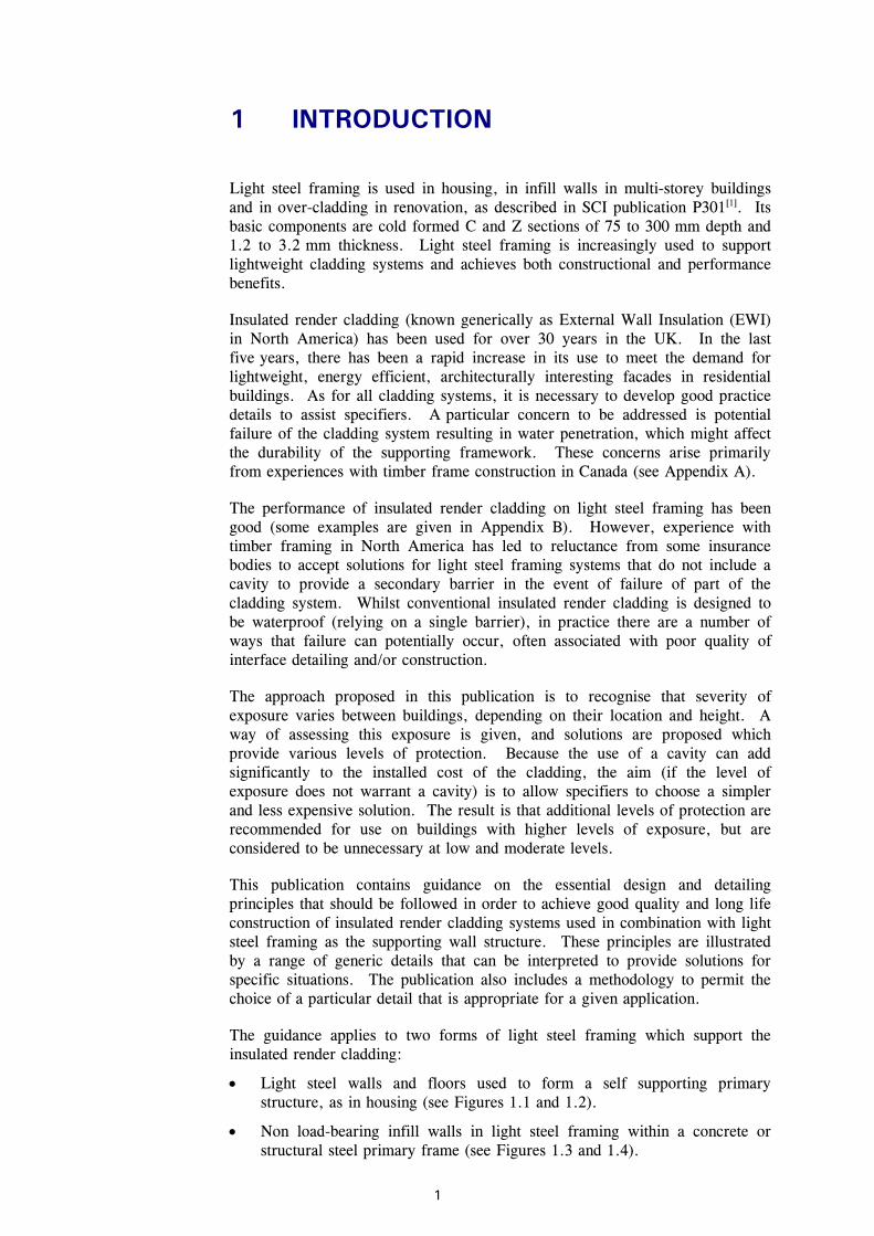
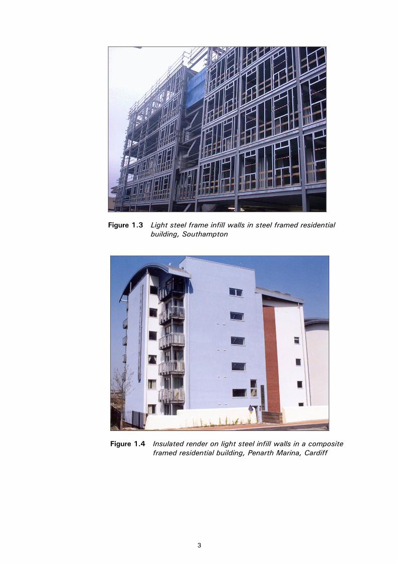
• Non load-bearing infill walls in light steel framing within a concrete or structural steel primary frame (see Figures 1.3 and 1.4).
The performance of all types of cladding systems can be affected by the quality of labour and materials used, and the weather and other conditions at the time of installation. The details suggested are designed to be sufficiently robust (by providing ‘back-up’ protection), and assume reasonable quality of workmanship on-site.
The same technology may be applied equally to multi-storey buildings, as illustrated in Figure 1.5. Insulated render cladding systems may also be used in combination with other cladding materials, as illustrated in Figure 1.6. The same general principles of providing ‘back up’ protection also apply to other cladding systems, such as the use of brick-slips or clay tiles.
Figure 1.1 Insulated render and brickwork cladding on light steel framed housing, Basingstoke
Figure 1.2 Insulated render on light steel framing for an apartment building, Fulham
In the UK, insulated render cladding systems that have been designed and applied by INCA∗ members have been in use for 30 years with no apparent problems. However, there are reported failures in North America of timber framed housing with insulated render cladding, which appear to be related to the use of poor quality timber and poor workmanship, as outlined in Appendix A. There is little reference to failure of the render itself, but rather recognition that interruptions such as windows, doors and fixings are critical.
Externally applied insulated render systems have been used successfully on a range of supporting materials in concrete and steel framed structures on commercial buildings, schools, hospitals, and private and social housing. General practice does not require the use of a cavity - these buildings have been insured for up to 20 years and have an assessed life of at least 30 years.
The use of light steel framing is relatively new (the first projects date from the late 1980s) and experience of the use of insulated render cladding on light steel framing has been good. A survey of early projects using this technology is presented in Appendix B.
The typical arrangement of layers in a non-cavity system supported by light steel framing is shown in Figure 2.1. A rigid moisture-resistant board provides impact resistance, rigidity and temporary weather protection during installation.
In the UK, the current view of the National House-Building Council (NHBC) for both timber and light steel framing is to require a minimum of 15 mm cavity to provide a means of drainage for any water that might enter behind the rendered cladding system. A cavity system is shown diagrammatically in Figure 2.2, which incorporates two substrate boards to form the cavity. The additional layers will add cost that may not be justified in all cases. In addition, there is a danger that the cavity will achieve little in terms of egress of moisture if its role is not properly understood.
Fundamental points when considering the provision of a cavity behind the insulated render that is drained but not ventilated are that:
• Rendered cladding, although vapour permeable, is not water permeable and water rarely leaks through the body of the cladding. This makes it fundamentally different from traditional cavity brick construction where the outer leaf of brickwork is both vapour and water permeable.
• Provision of a cavity will not exclude water from badly detailed junctions and penetrations.
• Effective removal of water that has entered a sealed system requires special drainage holes etc. The holes should be sufficiently large to allow drainage (and not capillary action), but should not allow significant ventilation.
∗ INCA provides an accreditation system for insulated render cladding systems and installers, whose performance is supported by latent defect insurance schemes. The INCA members are also responsible for the installation process. The guidance in this publication is appropriate to the use of these cladding systems as applied to light steel framing
• The incorporation of a cavity behind the insulated render layers may have implications for heat loss through the external wall and localised cold bridging, particularly at openings into the cavity to allow drainage. Significant ventilation may reduce the thermal insulation provided by the external insulation.
• Provision of a cavity may require additional measures to prevent spread of fire through the cavity. Any fire prevention measures must also permit free drainage of the cavity.
3.1 Design criteria and accreditation The overall performance of any cladding system is affected by the exposure conditions, the quality of the materials used and their longevity, and the workmanship on-site. Aspects of the construction system considered to be most at risk from deficiencies, as far as water penetration in any cladding system is concerned, may be identified as:
• Interfaces with windows and doors and other elements or materials.
• Detailing at joints, and allowance for movements.
• Movement of, and dimensional inadequacies in, the supporting structure.
• Construction process and buildability, e.g. site building or pre-fabrication.
• Sensitivity to on-site workmanship and weather conditions during installation.
Suppliers’ certificates generally cover the use of insulated render systems applied to blockwork, but the integrity of the system itself is independent of the supporting structure or medium, provided the supporting structure is sufficiently rigid and dimensionally stable support, as is the case with light steel framing.
Insulated render cladding systems with appropriate accreditation can be classified as Type 4 insulated cladding for permeability to water, as defined in UEATC MOAT No 45[ 2 ]. It is considered that such cladding systems are suitable for geographic regions classified as having ‘very severe’ exposure to wind driven rain when assessed in accordance with reference to BS 5628-3[3 ] and BS 8104[4]. Attention is therefore focused on junctions between the render and adjoining components forming the primary barrier, and the secondary seals, flashings, drainage systems etc. that will be used to safely discharge any water that penetrates this barrier.
The scope of the guidance given in this publication is limited to the use of light steel framing in ‘warm-frame’ or similar designs, where the structural framework is not subject to condensation, as defined in BRE Digest 465[5]. The recommended details and guidance assume sufficient insulation is present on the outside of the frame to ensure that a dew point does not occur behind the outer surface of the external insulation attached to the light steel frame (Ref. BS 5250[6]). This ensures that condensation does not occur internally or on the light steel framework.
The effects of drying to the interior of the building are not considered to be a suitable mechanism for water management and have therefore been ignored.
The prevention of water entry is only one of several important considerations in the design of insulated render cladding systems supported by light steel framing. These include, but are not limited to:
• fire resistance, including the effect of barriers or cavities
• acoustic insulation
• air-tightness
• deflection control
• structural stability
• impact resistance
• ease of installation
• maintenance requirements
• security considerations
• design life
• aesthetics.
Designers must satisfy themselves that all relevant requirements have been met with respect to their individual buildings. The good practice guidance in Section 5 responds to the need to satisfy these criteria, but it may be necessary to adapt the chosen details to satisfy particular project and site requirements.
3.2 Robust performance by design The performance requirements and the build-up of layers in a non-cavity insulated render cladding system are presented in Table 3.1. Typical materials that satisfy these performance requirements are also presented. All correctly installed ‘single barrier’ systems can be regarded as being waterproof. Thus, a detail advocated for low exposure, will be as waterproof as one suggested for high exposure.
Nevertheless, good practice details should recognise the need to allow for possible problems in installation, or possible degradation over time. The difference between details with different ratings is their degree of robustness to water ingress or condensation, i.e. what happens if the primary single barrier fails, due perhaps to poor workmanship or deterioration over time? This publications presents details that achieve robust long term performance in both the choice of cladding and jointing method. (For comparison, in the publication ‘Timber Frame Construction’ 3rd Edition 2001[ 7 ] Chapter 9, the details at windows do not show any secondary barriers).
This publication uses a scoring system by which the systems can be rated by their exposure level and other parameters. The solutions proposed in Section 5 offer four levels of robustness that may be related to general levels of exposure (Sheltered, Moderate, Severe and Very Severe). In the details that are presented, the proposed jointing methods are score-matched to the cladding systems to avoid multiplication of options.
3.3 Interfaces with windows and doors In a conventional modern house, for each square metre of wall surface, there will be on average two-thirds of a linear metre of window junction that potentially is a source of water ingress. For this reason, the details recommended in this publication focus on the design of window heads, jambs and sills, particularly methods of sealing the window to surrounding walls and the disposal of any water that does manage to enter the cladding system.The principle of discharging of water downwards and outwards through the wall construction, requires that attention should be given to the window head and jambs, and most importantly to the sill. Similar principles should be applied to other breaks in the cladding system, such as at balconies, parapets, service penetrations, flues, external connections etc. Guidance on the design of windows is given in BRE Digest 377[8].
3.3.1 Integration of windows with adjoining cladding Face-sealed (single barrier) systems link the primary barrier formed by the render to the windows. Use of proprietary mastic sealants between the insulated render and the window is not considered to be reliable as the sole barrier to water entry.
Solutions incorporating a secondary barrier are dependent upon a waterproof layer to provide extra defence. For example, a flexible membrane or waterproof substrate board is often placed ‘behind’ a cavity. The relationship between the location of the waterproof layer and the doors and windows is an important design issue, because where a secondary barrier is used, it must be linked to the openings. The resulting details may become more complicated.
Water that enters a cladding system with a secondary barrier must be discharged effectively when it meets the perimeter of a window or other horizontal obstruction, such as a deflection joint. This is relatively easy to achieve when there is a membrane that can be lapped over the window frame or turned to the outside. Cavities without flexible sheet membranes are more difficult to detail.
In some existing recommendations, a sloping channel is provided above the window to divert water away from the window head. The most likely source of water at this point would be from a defective window (or other penetration) above. Immediate discharge would be preferred to diversion of water, which has the potential to cause damage further down the cladding.
3.3.2 Sill design Window sills are a difficult part of the window to design. The main difficulty is achieving the required overlapping of components while retaining flexibility/practicality of sequencing of assembly. In traditional masonry cavity or brick-veneer construction, a sub-sill tray is built into the brickwork as the construction proceeds. This tray extends into the jambs and across to the inner leaf of the wall thus allowing windows to be installed during or after construction of the brickwork.
A similar approach can be used with insulated render by providing a sub-sill to be installed by the builder or framing sub-contractor during or immediately after the installation of the frame. A sub-sill largely provides the water exclusion function, thus allowing greater flexibility in design and installation of the windows.
Where there is no sub-sill tray, the ends of the sill itself must be overlapped by the jambs, with the sill passing under the window at least back to the rear of any membrane or cavity. These details are presented in Section 5 A typical window with its sills in an insulated render cladding system is shown in Figure 3.1. Where there is a sub-sill tray, the tray must likewise extend into the jambs and under the window. Turn-ups or other method of damming, such as site-applied standing seams of sealant, are required on the sill or sub-sill to prevent water flow off its back or ends. Drainage holes can be provided simply by gaps in the tape on top of the sill, and allow the discharge of water to the outside.
Junctions of jambs and sills are the most vulnerable part of the window in terms of potential failure zones. Sills are often designed to stop short of the jamb faces and be sealed with horizontally exposed sealants rather than to pass under the jambs to discharge water that has entered the vertical joints (as in traditional construction). They may also be fixed and sealed to the face of the window frame rather than pass under it. Whilst easing the detailing and construction process considerably, use of sealants and their adhesion to adjacent components makes this type of solution less reliable than the alternatives shown in Section 5.
Figure 3.1 Window sill detail in insulated render cladding system
3.3.3 Position of window in depth of wall The position of the window frame in relation to the depth of the wall can have a significant effect on the ease of detailing of the insulated render cladding. Therefore, it is suggested that constructional as well as architectural requirements should be taken into account in terms of window positioning.
Although designers may prefer windows either to be deeply recessed into the wall or, alternatively, level with the outer wall surface, to minimise the potential for water ingress, the windows should be placed with their outer face level with the waterproof plane (membrane). This geometry allows the simplest possible detailing of the membrane overlap around the window and also ensures good fixing conditions. Placing the window face in the plane of the membrane also ensures that any drainage cavities are kept outside the face of the window and simplifies the sealing of the rendered jambs to the window. Alternative
positions of the window face should be carefully considered and appropriate details developed that will ensure proper drainage and discharge of water.
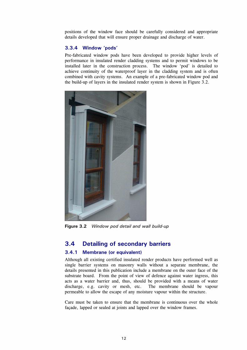
3.3.4 Window ‘pods’ Pre-fabricated window pods have been developed to provide higher levels of performance in insulated render cladding systems and to permit windows to be installed later in the construction process. The window ‘pod’ is detailed to achieve continuity of the waterproof layer in the cladding system and is often combined with cavity systems. An example of a pre-fabricated window pod and the build-up of layers in the insulated render system is shown in Figure 3.2.
Figure 3.2 Window pod detail and wall build-up
3.4 Detailing of secondary barriers 3.4.1 Membrane (or equivalent) Although all existing certified insulated render products have performed well as single barrier systems on masonry walls without a separate membrane, the details presented in this publication include a membrane on the outer face of the substrate board. From the point of view of defence against water ingress, this acts as a water barrier and, thus, should be provided with a means of water discharge, e.g. cavity or mesh, etc. The membrane should be vapour permeable to allow the escape of any moisture vapour within the structure.
Care must be taken to ensure that the membrane is continuous over the whole façade, lapped or sealed at joints and lapped over the window frames.
3.4.2 Substrate boards Substrate boards or sheathing board provide support to the insulated cladding and may form a cavity behind the cladding system, as illustrated in Figure 2.2. The substrate board is required in non-cavity systems and will often be provided in cavity systems. The performance requirements for these boards depend on the form of construction and their location within the cladding system. In general terms, the performance requirements of the substrate boards are:
• Resistance to wind action, depending on the means of attachment of the insulation to the support structure.
• Weather resistance in the temporary condition during construction.
• Moisture resistance to any water that may enter the system.
• Impact resistance, particularly in ground floor applications.
• Airtightness to minimise air infiltration for thermal efficiency.
• Fire resistance (mainly to externally occurring fires).
• Acoustic insulation close to busy roads or rail lines.
Suitable board materials include cement particle boards, moisture resistant grade plywood, or chipboard with moisture resistant covering, or cementitious or fibre-cement boards of various types, as given in Table 3.1. The joists should be taped or sealed by a flexible acrylic sealant for air and water-tightness.
3.4.3 Continuity of cavities If a cavity is required, it should be continuous and drained, but unventilated, i.e. it should not allow significant air movement. This requirement for continuity and drainage includes re-entrant areas, such as deep window jambs.
3.5 Dimensional coordination and tolerances Whilst problems may be experienced on site with light steel framing and insulated render, as with any other building system, they are often the result of poor communication and coordination. The lead designer (e.g. the architect) should guide the design and detailing process in order to coordinate the input from specialist suppliers (designers) of:
• Light steel framing.
• Insulated render.
• Joinery (windows), and any other items that penetrate the render.
Coordination is needed to ensure good dimensional control, resulting in correct alignment and jointing at windows, etc. The use of well drawn, large scale details with coordinating planes clearly shown is the best way to ensure correct interfacing of all the components.
Tolerances in installation must also be given due consideration in detailing. Light steel framing is often used for infill walls in primary structures formed from hot-rolled steel or reinforced concrete frameworks. Alternatively in low-rise buildings, the light steel framing may be the primary structure, supported on in-situ foundations. In both cases, geometric deviations in the adjacent structure or foundations must be recognised and allowed for in the interface details with the infill walls and its cladding.
Structural steelwork is generally erected to tolerances plus or minus 10 mm per storey and allowance for this must be made. Additional allowances should be made at the head of the infill walls to allow for deflection of the primary structure, and a total differential movement of 20 mm is usually permitted. Further allowance should be made to avoid geometric deviations which cause the primary to encroach into the cladding zone. A good way to allow for the combination of these tolerances in the primary structure is to set the outer face of the light steel frame 20 mm outside of the designed face of the primary frame. The outer face of the light steel frame then becomes the coordinating plane for the render system and placement of windows.
The position of windows in plan and height can be further defined by other coordinating planes that define the structural opening position and size within the light steel frame. Typically, the light steel frame manufacturer will increase window openings by 3 mm all around to avoid small manufacturing deviations affecting the designed window opening. The window manufacturer will work to 5 or 10 mm less than the nominal opening sizes, to allow for fitting and provision for fixing brackets.
3.6 Interfaces with other materials or features The ‘mixed’ use of materials in a particular building façade should be considered in the design of the cladding system, and typical design cases are:
• Brickwork at ground and possibly first floor level, with insulated render cladding above (see Figure 3.3).
• Timber or metallic cladding adjacent to rendered cladding (see Figure 1.6).
• Brickwork or concrete featured columns.
• Featured stone lintels above windows or doors.
• Parapets and other projections.
• Balconies and attachments.
The common use of brickwork at ground floor level and various forms of lightweight cladding above should allow for a ‘step-out’ and flashings at the brickwork, which is thicker than the cladding above. In addition, balconies or access walkways often project from the façade, and their attachment represents a local detailing problem. Figure 3.4 shows a good example of detailing of parapets and balcony attachments. In multi-storey buildings, effective detailing at floor positions can often be achieved by using a light metallic facia to which the render is bonded, as illustrated in Figure 3.5.
Figure 3.5 Insulated render used in multi-storey building at Sunderland
Royal Hospital showing detailing at floor lines
3.7 Durability of galvanized steel in ‘warm frame’ construction
The standard form of corrosion protection for the cold formed steel sections used in light steel framing is a continuous dip zinc coating applied as a pre-coat to the roll of strip steel from which the sections are formed. Galvanized steel strip is supplied to the specification in BS EN 10326[ 9 ], which has replaced BS 2989 and BS EN 10147.
Galvanized strip steel is produced with a standard G275 coating, corresponding to 275 grams of zinc per square metre summed over both faces of the steel strip. This corresponds to approximately 0.02 mm overall thickness of zinc per face. Other coating thicknesses are available for special applications.
The zinc bonds to the steel substratum and deforms around the bends during forming, even in complex section shapes, without cracking or becoming detached. Because of this, galvanizing has become the standard method for corrosion protection of cold formed steel in a wide range of applications not subject to direct weathering or exposed conditions.
Hot dip galvanizing after manufacture is applied to more complex steel fabrications. The coating should comply with BS EN ISO 1461[10], which has replaced BS 729. More guidance on this technology is available from the Galvanizers Association. A new standard, BS EN ISO 14713[ 11 ], provides information on zinc and aluminium coatings and their expected design lives in different environments.
The performance of galvanized (zinc coated) steel components within warm-frame applications is very good. Research has shown that the predicted design life of the standard G275 coating, based on the measured loss of zinc from the strip steel, is over 200 years in warm frame applications, provided that the building envelope is properly maintained. The evidence for this conclusion is based on measurement of zinc loss on light steel frames in housing and other
applications and various locations. Results are presented in the SCI publication P262, Durability of light steel framing in residential buildings[12].
The following table summarises the expected design life of galvanized steel sections in common applications in buildings. Furthermore, steel does not shrink, warp, or creep under load, and therefore does not contribute to cracking or deterioration of the non-structural elements and finishes.
Table 3.2 Design life of galvanized light steel sections in common applications in buildings
Product application Environmental condition Design life
Walls and internal floors in warm-frame applications
No risk of water ingress or condensation
> 200 years
Roof structures (insulated) Low risk of condensation 100 years
Purlins and side rails in metal cladding
Low risk of condensation; some dust and pollution
60 years
Infill external walls in multi-storey buildings
Warm frame and no risk of water ingress
>200 years
Sub-frames to over-cladding panels
Low risk of water ingress; some risk of condensation
60 years
* The design life relates to steel with G275 coating. G275 refers to the weight of standard zinc coating (i.e. 275 g/m2)
This Section describes the choice of an appropriate detail for insulated render systems supported by light steel framing.
4.1 Assignment of performance scores to details When considering a particular detail, each component that contributes to the overall robustness to water ingress or condensation should be assigned a score. This is identified by the term ‘robustness’ or ‘back-up’ in the event of poor performance of a composite over time. Scores for the cladding components are then combined to give an overall performance score for the cladding. Similarly, scores for joint components are combined to give an overall performance score for the joint detail. The recommended details shown in Section 5 are grouped according to their scores.
The score for the wall construction should meet the minimum system performance score in Table 4.1 for the exposure conditions under consideration. The score for each joint detail should meet the minimum system performance score in Table 4.2. Clearly, the assignment of scores for individual components is a subjective and, in the interests of practicality, is a relatively simplistic process. Despite the simplicity of this approach, high scoring details can nevertheless be assumed to provide increased levels of robust performance.
It should be emphasised that appropriate test evidence for other cladding systems provides an acceptable way of demonstrating robustness to water ingress.
4.1.1 Component scores Cladding
An insulated render system with third party certification should always be used. This is given a score of 2. The majority of current certifications apply to the use of insulated render systems on blockwork, but in the future, it is expected that most systems will be fully certified for use on light steel framing. All component scores are summarised in Table 4.1.
Cavities behind the insulated render that provide a reliable drainage plane and prevent migration of water to the ‘inner’ structure are given a score of 1. Drainage meshes or grooved insulation are considered to provide effective drainage planes. If grooved adhesive is used to form the drainage plane, this should only be given a score of 0.5 to reflect greater sensitivity to variations in workmanship (which may affect the width of the drainage channels).
Breathable flexible membranes are given a score of 1. Continuous, breathable liquid membranes can also be considered to act as a membrane, but may be more susceptible to variations in workmanship and are thus limited to a score of 0.5.
Table 4.1 Cladding component scores used in selecting an appropriate detail
Score
3rd party certificated insulated render system 2
Cavity behind the external insulation 1
Drainage mesh and membrane 1
Water-resistant sheathing board (taped or sealed joints) 1
Breathable flexible membrane without cavity 1
Grooved insulation mechanically fixed 0.5
Grooved adhesive 0.5
Breathable liquid applied membrane without cavity 0.5 Joints
Sealants protected from the weather and supported by a third-party certification of fitness for purpose and quality assurance procedures for their application are given a score of 1. Exposed sealants are limited to 0.5. Compressible hydrophobic foam strips are given a score of 1. Each separate drainable cavity adds a score of 1. Joint component scores are summarised in Table 4.2:
Table 4.2 Joint component scores used in selecting an appropriate detail
Score
Protected sealants (internal) 1
Exposed sealants (external) 0.5
Compressible foam strips 1
Drainable cavity (for each cavity) 1
Flexible impermeable strip at joint (flashing) 1
For an aggregate score higher than 2 to be achieved for the whole window, regardless of the number of lines of sealant or cavities, it is necessary to design the sill to collect and to discharge any water that has penetrated the jamb to the exterior. Prefabricated window pods possess most of the above features and should be assessed in the same manner.
4.1.2 Degradation over time When considering levels of protection at junctions, it should be remembered that many sealants require replacement at 10 - 15 year intervals, and even if the sealant itself does not fail, its bond to adjoining surfaces might deteriorate. Exposed sealants might stay in place as gap fillers but might also permit capillary action.
4.2 Determination of exposure category 4.2.1 Wind driven rain index Wind pressures on buildings depend on the building height and proportions, as well as site topography, location and elevation above sea level. Wind pressures can be determined using BS 6399-2[13], which considers these conditions. When combined with an allowance for rain intensity, the country may be divided into zones based on four exposure categories, namely Sheltered, Moderate, Severe and Very Severe.
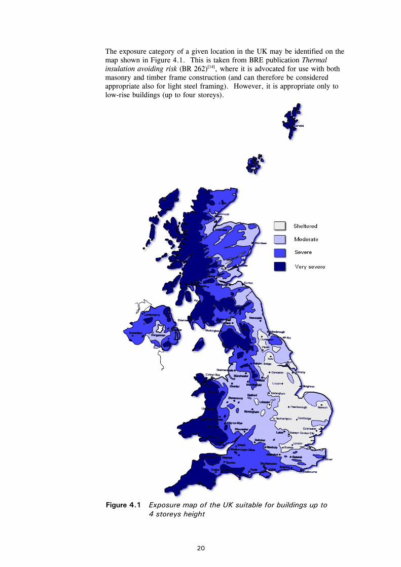
The exposure category of a given location in the UK may be identified on the map shown in Figure 4.1. This is taken from BRE publication Thermal insulation avoiding risk (BR 262)[14], where it is advocated for use with both masonry and timber frame construction (and can therefore be considered appropriate also for light steel framing). However, it is appropriate only to low-rise buildings (up to four storeys).
Figure 4.1 Exposure map of the UK suitable for buildings up to
Table 4.3 includes wind driven rain values that correspond to each exposure category according to BRE 262. The minimum performance score of the system is also indicated. For more accurate exposure rating for a particular site, BS 8104[4] allows an accurate determination of wind-driven rain values, that can be related to an exposure score. ‘Spell’ is defined in BS 8104 as being of variable length and includes several periods of wind driven rain interspersed with periods of up to 96 hours without appreciable wind driven rain.
Minimum system performance score - a measure of failsafe-ness Exposure
category Wind driven rain
(litres/m2 per spell) Wall construction Joint details etc
Sheltered <33 2* 2*
Moderate 33 – 56.5 2 2
Severe 56.5 – 100 3 3
Very severe >100 4 4
*Systems with a performance score of 2 is the minimum acceptable
4.2.2 Application to multi-storey buildings Wind-driven rain is also a function of wind speed, which varies with building height. BS 8104 gives a more general method, which is a function of various parameters including building height. In the absence of more detailed calculations, it is assumed that the exposure category is increased by one step, e.g. moderate becomes severe for buildings of over four storey height. This applies only to the floors above the fourth, but for simplicity of detailing may be used for all levels.
Multi-storey buildings are often constructed as steel or concrete primary frames with non load-bearing light steel walls. In this case, generic cladding details without a cavity are more widely used in commercial buildings and hospitals.
4.3 Choice of detail Having identified the exposure category and corresponding minimum performance score for a given site, a detail must be chosen or developed that will provide an adequate performance score. This must be at least equal to the minimum score in terms of both the wall and its joints.
Architects, clients, local authorities or insurers may specify a better performance score from those proposed in the table, but higher levels of back up are likely to add cost to the system.
A proposed way to define a suitable detail is to consider the generic solutions shown in Section 5, with appropriate modification to suit particular circumstances. Alternatively, a designer may:
• Use the rating system explained in Section 4.1 to develop an appropriate detail, supplemented by performance testing.
• Adopt a proprietary solution that has been shown to perform acceptably well for the particular exposure category.
5.1 Introduction to details The range of possible solutions needed to cover all practical applications of insulated render cladding is almost limitless when considering the variables such as type of membrane, type of substrate board, method of fixing insulation (adhesive or mechanical), designs of joint seals, window jambs, heads and sills and the level of robust performance that is required. Thus the details given in this Section are designed to cover the most common cases, and at the same time to express principles that can be extended to cover other design requirements. A primary objective is that the assembled components should be naturally self draining in the event of breach of external seals, and should not allow moisture contact with the light steel framing.
In the proposed cladding details, the render and insulation system is shown only as a cladding zone, the details and performance of which as a weather barrier should be validated separately and independently by each individual insulation render designer/supplier.
The window sections shown in the details are presented for illustrative purposes only and do not indicate any particular brand or design of window. Although it is recommended that metal windows should incorporate a thermal break, the principal requirement with respect to water exclusion is for a sufficiently wide frame to permit sealing of render and insulation to the face of the window frame, as shown. Similarly, other materials need not be limited to those shown in the recommended solutions; all types of insulation, substrate boards and insulation carrier systems may be considered. Window ‘pods’ provide a successful means of locally sealing the render cladding and improve speed of installation. Their use is not explicitly included in these details, but they are clearly beneficial in preventing water ingress.
The details given in this publication are intended to be generic and can be provided by a range of installers, provided that they are covered by third party certification, which also includes the sealants. However, other details can be used if substantiated by experience, certification and testing. A number of recognised companies provide reliable products that include quality assurance programmes and detailed supervision (see Foreword). Their certified ‘single barrier’ solutions have a proven performance over 10 to 25 years when applied to blockwork and timber and light steel framing systems.
Other guidance on the energy efficiency aspects of external insulation systems[15] and modern methods of construction[ 16 ] is given in recent publication by the Energy Saving Trust.
5.2 Systems suitable for sheltered and moderate exposure conditions
Figures 5.1 to 5.4 show appropriate details achieving a performance score of 2 or more. The following general points should be noted:
• All of the details include a weather-resistant substrate board. this board provides for external fire protection of the structure, convenience of fixing the cladding, acoustic attenuation, robustness to impact, etc.
• The substrate board also provides weather resistance during the construction process, and should be selected accordingly.
• The minimum overlay of the insulated render onto the window frame should be 20 mm at the jamb and head.
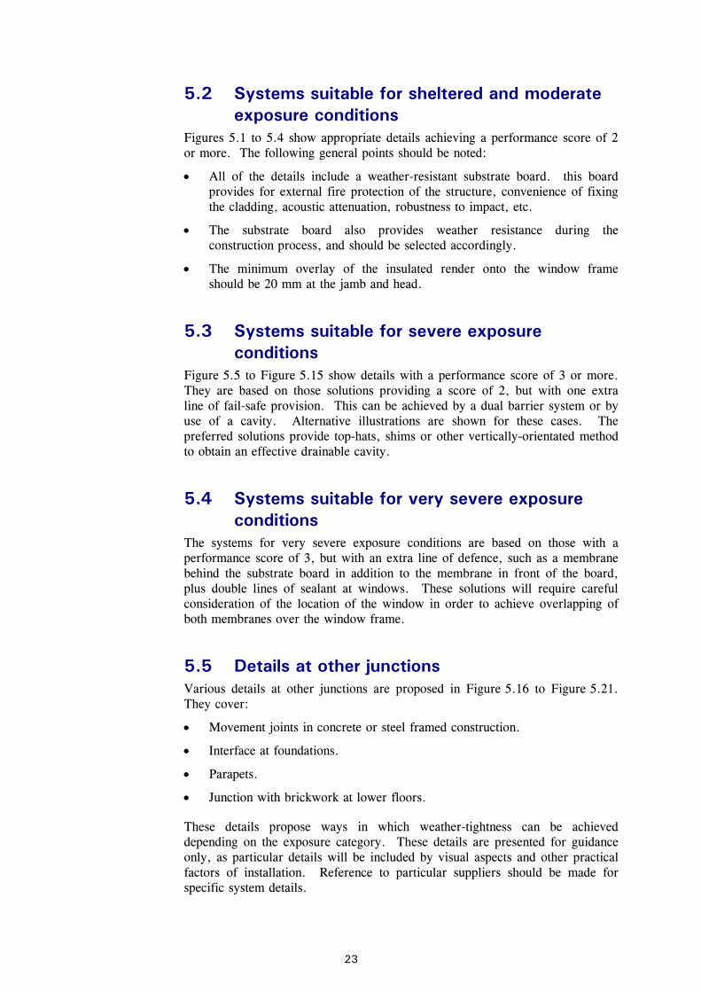
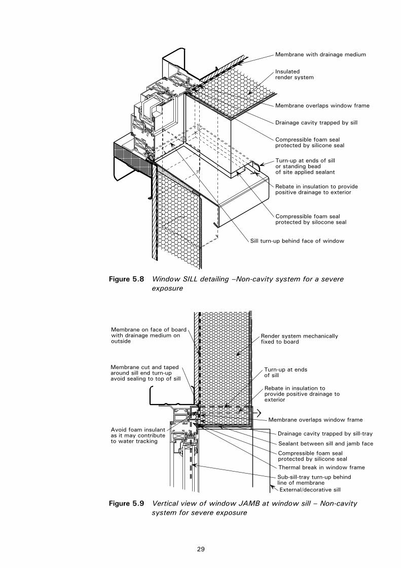
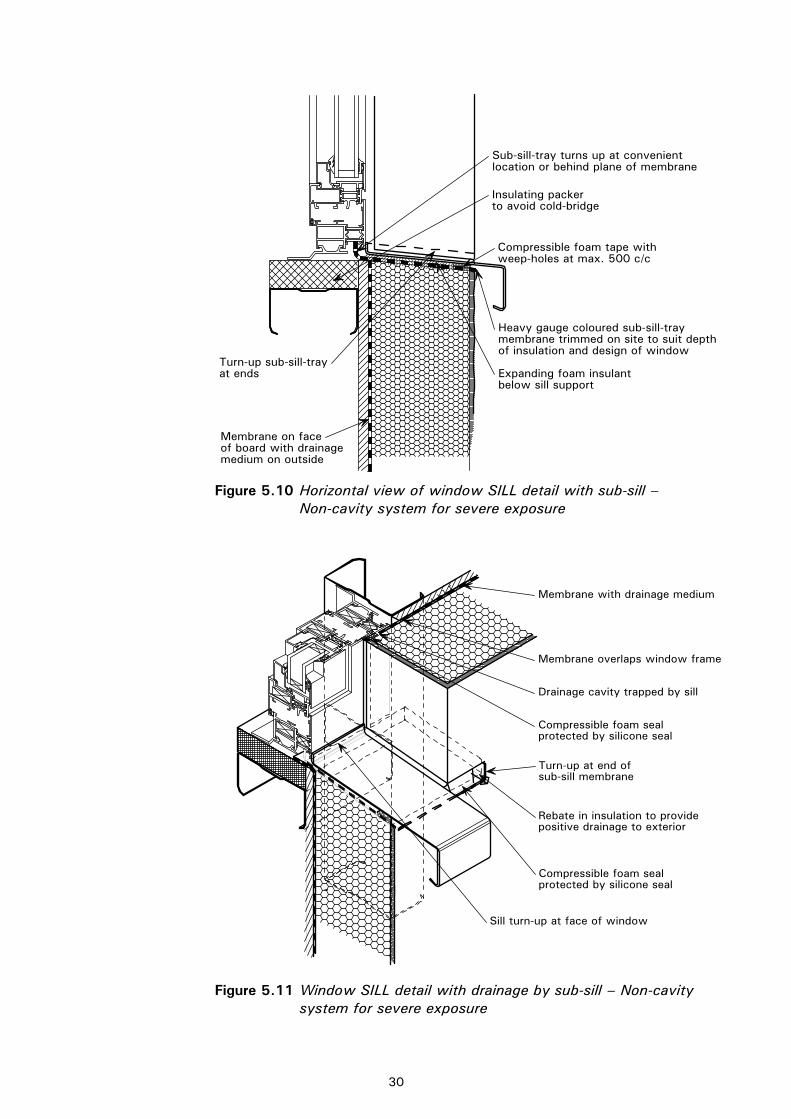
5.3 Systems suitable for severe exposure conditions
Figure 5.5 to Figure 5.15 show details with a performance score of 3 or more. They are based on those solutions providing a score of 2, but with one extra line of fail-safe provision. This can be achieved by a dual barrier system or by use of a cavity. Alternative illustrations are shown for these cases. The preferred solutions provide top-hats, shims or other vertically-orientated method to obtain an effective drainable cavity.
5.4 Systems suitable for very severe exposure conditions
The systems for very severe exposure conditions are based on those with a performance score of 3, but with an extra line of defence, such as a membrane behind the substrate board in addition to the membrane in front of the board, plus double lines of sealant at windows. These solutions will require careful consideration of the location of the window in order to achieve overlapping of both membranes over the window frame.
5.5 Details at other junctions Various details at other junctions are proposed in Figure 5.16 to Figure 5.21. They cover:
• Movement joints in concrete or steel framed construction.
• Interface at foundations.
• Parapets.
• Junction with brickwork at lower floors.
These details propose ways in which weather-tightness can be achieved depending on the exposure category. These details are presented for guidance only, as particular details will be included by visual aspects and other practical factors of installation. Reference to particular suppliers should be made for specific system details.
5.6 Installation sequence The installation sequence for site-built insulated render cladding is important because it influences the integrity of the completed cladding system. Partially prefabricated cladding systems may also be used, but the finishing layer is generally applied on-site. The following sequence should generally be followed:
• Install light steel framing, either in elemental (‘stick-built’) form or as prefabricated wall panels with window or door openings.
• Attach moisture-resistant sheathing board for weather-tightness early in the construction sequence.
• Attach mitred and cut membrane around window openings. Tape and seal joints in sheathing board and attach any acoustic insulation and fire breaks.
• Install window frame and seal around the window frame to the membrane (the installation of the window frame is a specialist operation and is the responsibility of the supplier).
• Attach insulation and fix to the sheathing board. Apply mastic to the insulation around the openings.
• Apply base coat over the insulation, including glass fibre reinforcement (with additional reinforcement at the corners of windows).
• Apply expanding foam and sealants around windows (this last operation is the responsibility of the window supplier, as it ensures the integrity of the sealants around the windows).
• Apply primer coat and finish to the render.
Systems with additional ‘back-up layers’ require further installation operations. Pre-fabricated window pods can improve speed of installation and allow for later installation of windows off the critical path.
5.7 Details of non-cavity systems for sheltered or moderate exposure
The following details may be used in applications of sheltered or moderate exposure. Table 5.1 defines the performance score of the various components.
Table 5.1 Summary of performance score (for details in Figures 5.1 to 5.4)
Score
Wall
Certified insulated render* 2
Total score 2
Joint at jamb
Compressible foam seal 1
Silicone seal 0.5
Drainage cavity in jamb 1.0
Total score 2.5
* The majority of systems are certified for use on blockwork currently
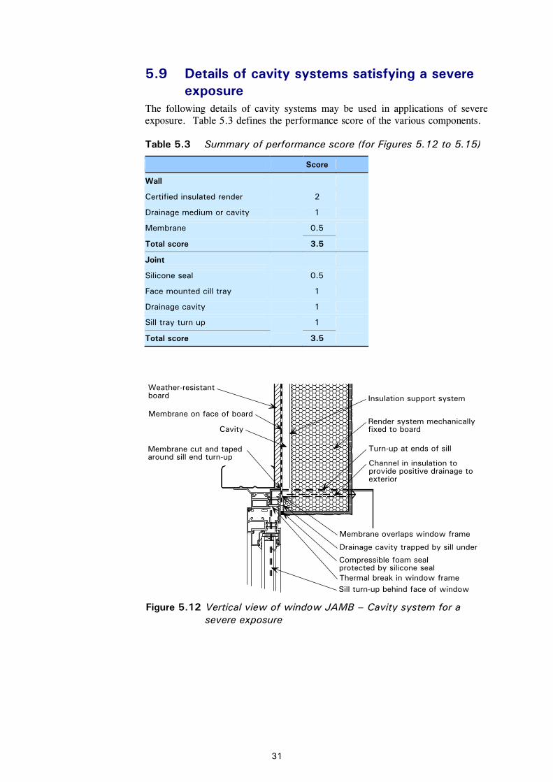
5.9 Details of cavity systems satisfying a severe exposure
The following details of cavity systems may be used in applications of severe exposure. Table 5.3 defines the performance score of the various components.
Table 5.3 Summary of performance score (for Figures 5.12 to 5.15)
Score
Wall
Certified insulated render 2
Drainage medium or cavity 1
Membrane 0.5
Total score 3.5
Joint
Silicone seal 0.5
Face mounted cill tray 1
Drainage cavity 1
Sill tray turn up 1
Total score 3.5
Insulation support system
Membrane on face of board
Cavity
Membrane cut and taped around sill end turn-up
Turn-up at ends of sill
Render system mechanicallyfixed to board
Channel in insulation to provide positive drainage toexterior
Thermal break in window frame
Compressible foam seal protected by silicone seal
Drainage cavity trapped by sill under
Membrane overlaps window frame
Sill turn-up behind face of window
Weather-resistantboard
Figure 5.12 Vertical view of window JAMB – Cavity system for a severe exposure
5.10 Other details The following figures show details of movement joints in muti-storey buildings, details of ground floors and parapets, and junctions with brickwork.
Compressible foam sealprotected by silicone seal
Mineral fibre
Weather-resistantboard
Figure 5.16 Vertical view through movement joint at attachment of
non-cavity cladding system to a concrete frame
Render system
Compressible foam sealprotected by silicone seal
Weather-resistantboard
Deflectionhead
Mineralfibre
Figure 5.17 Section through horizontal movement joint in non-cavity cladding system
APPENDIX A Experience of rendered cladding on timber framing in Canada
The Commission of Inquiry into the Quality of Condominium Construction in British Columbia† drew conclusions from the failures that had been reported:
The Commission’s report concluded that a number of factors, including a failure of the building process, building science issues, overheated housing market, and a poorly interpreted building code, led to a disintegration of the quality of residential construction in BC. This judgment received widespread endorsement from the building industry, architects, inspectors and the general public.
Numerous presenters, including housing representatives with commissioned engineer studies, architects, engineers, and warranty providers, told the Commission of building envelope failures as a result of poor or inappropriate design and shoddy workmanship. Not one example was brought forward where such buildings had been built to code. Instead code violations were the reason for the failure of the buildings.
Within the industry there is confusion in understanding and interpreting what is required by the building codes. There is also confusion and misunderstanding regarding the nature of the leaky condo problem. Although discussion surrounding air barriers, vapour barriers and permeance are all interesting, they are not relevant to the problems facing British Columbia’s building envelope failures.
Building envelopes are failing because litres of water are entering the walls from the outside through poorly-designed roofs, balconies, and windows; because of badly-constructed joints, missing flashings, inappropriately lapped building paper, and thinly applied stucco.
There has been no evidence that building envelopes, constructed according to the building code, will fail. The Commission is aware that some building envelope systems, certain design approaches, and combinations of materials are conducive to higher standards than others. However, according to the extensive testimony received from numerous professionals, if the Building Code is followed—with a requisite understanding of building science—the building envelope systems will work.
The MEWS (Moisture Management for Exterior Wall Systems) tests carried out by The National Research Council of Canada confirmed that if seals in single barrier systems are faulty then leakage will occur, and that if secondary defensive measures are used (drainage) then the effects of the initial leakage will be minimised. There is however no evidence to suggest that current quality cladding systems will fail in the body of the material except perhaps due to severe accidental damage or cracking due to excessive movement. The Commission of Inquiry into the Quality of Condominium Construction in British Columbia noted: Face sealed wall assemblies can and do work under certain environmental conditions. They are relatively inexpensive wall assembly systems and, ironically, protect against moisture from vapour diffusion and interior airflow.
† The Commission of Inquiry into the Quality of Condominium Construction in British Columbia, by Dave Barrett, Commissioner, submitted to the Lieutenant Governor in Council, Government of British Columbia, March 2000, available from Ministry of Social Development and Economic Security, Victoria, BC, Canada, (www.sdes.gov.bc.ca)
The following background information is presented to illustrate the investigations on external wall insulation systems in USA and Canada.
American National Standard for Exterior Insulation and Finish Systems (EIFS) - ANSI/EIMA 99-A-2001
Exterior Insulation Finish Systems: Designing EIFS (Clad Walls) for a Predictable Service Life – Kevin C Day – Project Manager & Building Specialist in the Building Engineering Division of Morrison Herchfield Limited.
Standard Test Method for Determining the Drainage Efficiency of Exterior Insulation and Finish Systems (EIFS) Clad Wall Assemblies. – ASTM International Designation: E2273-03.
Guide to EIFS Construction EIFS Industry Members Association.
Report from task 2 of MEWS project – Description of 17 Large Scale Wall Specimens Built for Water Entry Investigation in IRC Dynamic Wall Testing Facility. – IRC RR-111
Report from task 6 of MEWS project – Experimental Assessment of Water Penetration and Entry into Wood-Frame Wall Specimens – Final Report. - Research Report 133. NRC-CNRC (National Research Council of Canada)
Report from task 8 of MEWS project – MEWS methodology for developing moisture management strategies. NRC-CNRC Report B1011.T8-02
Final Report from Task 8 of MEWS Project 8 – 03) – Hygrothermal Response of Exterior Wall Systems to Climate Loading: Methodology and Interpretation of Results for Stucco, EIFS, Masonry and Siding-clad Wood-frame Walls. Research report 118 NRC-CNRC
OAA Rain Penetration Control and Practice Guide. Ontario Association of Architects.
Model Quality Plan for Use of Drainage-Type Exterior Insulation and Finish Systems (EIFS) on One- and Two-Family Dwellings. NAHB Research Center, Inc.
EIFS-Drainable Systems – PATH Technology Inventory – Toolbase Services – Home and Building Industry’s Technical Information Resource.- NAHB Research Center.
ANSI/EIMA 99-A-2002 Exterior Insulation and Finish Systems (EIFS) 13.3.1 EIF Systems with Drainage
APPENDIX B Experience of insulated render cladding on light steel framing in the UK
As a background to this publication, the performance of early buildings constructed in the UK using insulated render cladding on light steel framing was investigated by site visits and discussions with users. The investigations on these buildings are summarised below:
TGI Fridays Restaurant, Croydon: (restaurant, early 1990’s)
Construction: Off-site prefabricated panels of Dryvit render on EPS insulation fixed to moisture resistant plasterboard on light steel framing and fixed to a single storey structural steel frame. Site joints in the sealant were made over closed backer rods in closed-cell insulation. The building has a flat roof.
Performance: No water ingress has occurred through the junctions between the render system and windows. However, the aluminium windows have leaked in driving rain. Mechanical impact damage from cars etc has caused localised hairline cracks in the render, but no water penetration has occurred. Slight cracking in the render has occurred adjacent to a large door, due to flexing of the frame, and worsened by impact. Near-horizontal surfaces on the parapets etc show signs of some dirt retention.
Construction: Single storey site-built light steel framing constructed over an existing masonry building. Dryvit render over EPS insulation attached to moisture resistant plasterboard substrate was fixed to the outside of the light steel studs. Additional mineral wool insulation was placed between studs. The building has a pitched roof with slates.
Performance: No problems of moisture penetration have been experienced. Intricately-shaped raised mouldings have also presented no problems.
Construction: Sto/Tellings render over EPS insulation on horizontal uPVC rails on calcium silicate substrate board was supported by Ayrshire light steel infill panels that were attached to a re-clad 1960’s concrete frame building. uPVC window frames and sills were added. Additional mineral wool insulation was placed between the light steel studs. The current condition of Kingston Bridge House is shown in Figure B1.
Performance: No signs of moisture penetration. Some staining on cornices on external surfaces. Some damage due to vandalism near the entrance.
Construction: Isoporock render over 70 mm Rockwool Lamella insulation attached to a Bitvent substrate board was supported by a load bearing two storey light steel frame. Additional mineral wool insulation was placed between the studs. Timber windows were used. The building has a pitched slate roof.
Performance: No water penetration, and generally good performance.
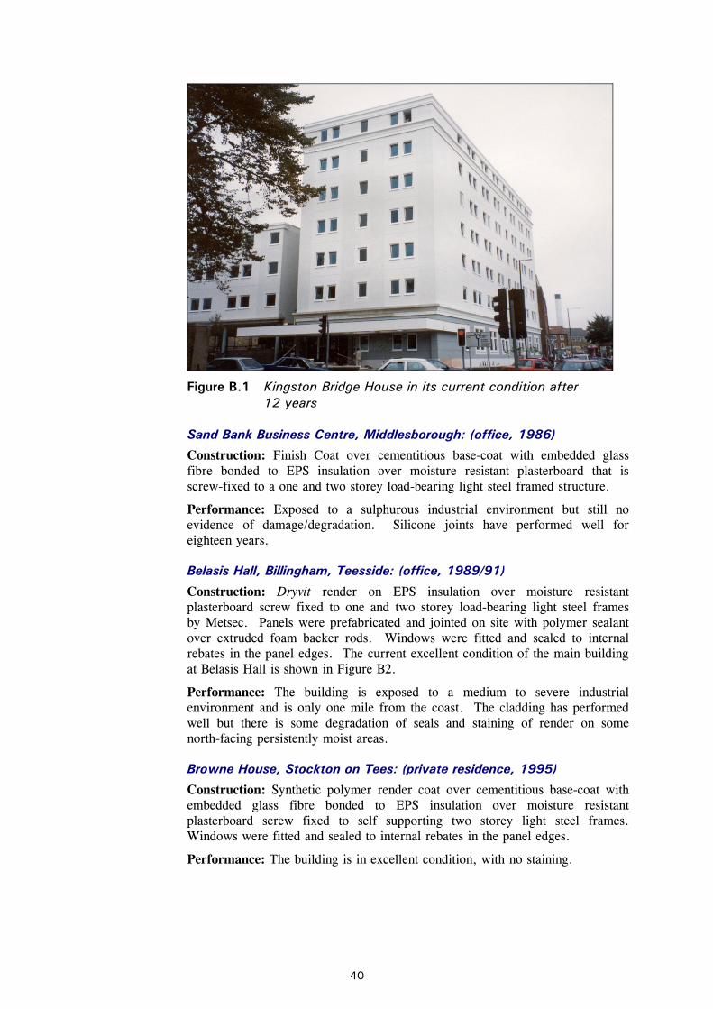
Figure B.1 Kingston Bridge House in its current condition after 12 years
Sand Bank Business Centre, Middlesborough: (office, 1986)
Construction: Finish Coat over cementitious base-coat with embedded glass fibre bonded to EPS insulation over moisture resistant plasterboard that is screw-fixed to a one and two storey load-bearing light steel framed structure.
Performance: Exposed to a sulphurous industrial environment but still no evidence of damage/degradation. Silicone joints have performed well for eighteen years.
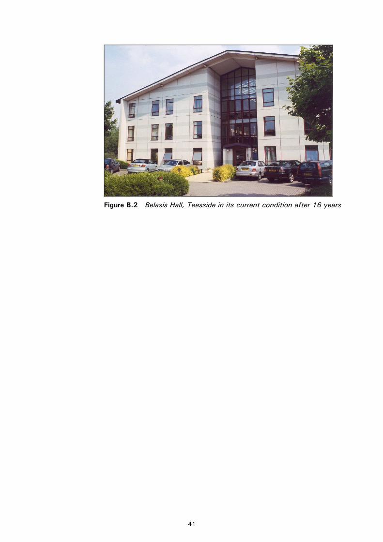
Construction: Dryvit render on EPS insulation over moisture resistant plasterboard screw fixed to one and two storey load-bearing light steel frames by Metsec. Panels were prefabricated and jointed on site with polymer sealant over extruded foam backer rods. Windows were fitted and sealed to internal rebates in the panel edges. The current excellent condition of the main building at Belasis Hall is shown in Figure B2.
Performance: The building is exposed to a medium to severe industrial environment and is only one mile from the coast. The cladding has performed well but there is some degradation of seals and staining of render on some north-facing persistently moist areas.
Browne House, Stockton on Tees: (private residence, 1995)
Construction: Synthetic polymer render coat over cementitious base-coat with embedded glass fibre bonded to EPS insulation over moisture resistant plasterboard screw fixed to self supporting two storey light steel frames. Windows were fitted and sealed to internal rebates in the panel edges.
Performance: The building is in excellent condition, with no staining.
Performance testing may be used to confirm the performance of details of a particular cladding system.
C.1 Test procedure The following procedures are recommended for testing of insulated render cladding systems on light steel framing:
Test Arrangement
The test rig for weather-tightness tests should be carried out to BS 6375[17] and BS EN 12865[ 18 ] and BS EN 12154[ 19 ] , and for comparison of the various systems, should comprise:
Four sample panels each 3 m × 3 m fitted together as a prefabricated light steel wall frame with its cladding attached to a structural steel frame to produce a 6 m × 6 m wall. Each panel should include a 1 m2 timber framed window. The horizontal and vertical joints between the panels are designed to be water resistant. Each of the four panels should match one of the four exposure specifications and include one centrally positioned window detailed as described for that exposure. Differences in thickness of the panels resulting from the different specifications will be accommodated in the fixings so that a flush exterior is presented.
The four panels are arranged so that the sample more likely to fail first is at the bottom so as not to corrupt observations on a panel of higher specification. All panels will be tested in one progressive operation of increasing exposure, beginning with the lowest specification. In this way, each specification will be tested at an appropriate level (at the maximum wind-driven rain value for that level) before being subjected to higher exposures as a result of testing the higher specification wall panels.
The specimens will finally be tested to 'very severe' exposure, as it is likely that the labour and supervision used at the test site will be equivalent to that required to satisfy a 'very severe' exposure in reality. Because of the potentially better conditions applying to a test, a deliberately flawed version of a 'very severe' exposure system should be introduced. This test is intended to demonstrate the operation of back-up barriers in the event of failure of primary seals.
C.2 Examples of a weather-tightness test on insulated render panel
A series of weather-tightness tests was carried out by Taylor Woodrow for the Telling Group of a non-cavity insulated render cladding system supported on a light steel sub-frame. These tests were required as part of the pre-construction trials on the cladding system that was used for the Royal Opera House in London.
The test panel was 4.35 m (storey high) × 2.5 m wide and included one openable ‘tilt and turn’ window.
In the test series to Part 1 of BS 5368, the measured deflection at a design wind pressure of 1.6 kN/m2 (1600 Pa) was 3.9 mm, which is less than the limit of 5.3 mm for this span. At a factored load of 2.4 kN/m2, no failure occurred and deflections reached 9.7 mm.
In the test series to Part 2 of BS 5368, air infiltration with vents sealed was measured in the range of 0.3 to 2.3 m3/hour (average of 1.0 m3/hour) over a pressure range of 50 to 600 Pa, which is much less than the limit of 1 m3/m2/hour at 600 Pa multiplied by an area of 6.5 m2 over which the measurements were taken.
In the test series Part 3 of BS 5368, no measurable water penetration occurred in the test.
It was concluded that the test met the specification and that correctly installed insulated render cladding system on light steel framing would not be subject to water ingress due to wind-driven rain.
1 GORGOLEWSKI, M. T, GRUBB, P. J. and LAWSON, R. M. Building design using cold formed steel sections. Light steel framing in residential construction (P301) The Steel Construction Institute, 2001
2 Guide for the assessment of prefabricated external wall insulation (Insulating Cladding Panels)
UEATC, Moat 45 British Board of Agrément 1990 3 BS 5628-3:2001 Code of practice for use of masonry, materials and
components, designs and workmanship BSI
4 BS 8104:1922 Code of practice for assessing exposure of walls to wind driven rain BSI
5 BRE Digest 465: U values for light steel frame construction BRE, 2002
6 BS 5250:2002 Code of practice for control of condensation in buildings BSI
7 Timber Research and Development Association Timber Frame Construction 3rd Edition, 2001
8 BRE Digest 377: Selection of windows by performance BRE, 1992
9 BS EN 10326:2004 Continuously hot-dip coated strip and sheet of structural steels: Technical delivery conditions: (replaced BS EN 10147) BSI
10 BS EN ISO 1461:1999 Hot dip galvanized coatings on fabricated iron and
steel articles. Specifications and test methods BSI
11 BS EN ISO 14713:1999 Protection against corrosion of iron and steel in
structures. Zinc and aluminium coatings: Guidelines BSI
12 POPO-OLA S, BIDDLE, A.R. and LAWSON, R. M.
Buildings design using cold formed steel sections. Durability of light steel framing in residential building (P262) The Steel Construction Institute, 2000
13 BS 6399-2:1997 Loading for Buildings. Code of Practice for Wind Loads
15 External insulation systems for walls of dwellings Energy Efficiency Best Practice in Housing, Energy Saving Trust, 2004
16 Building energy efficient buildings using modern methods of construction Energy Saving Trust, 2005
17 BS 6375 Performance of windows BS 6375-1:2004 Classification for weathertightness and guidance on selection and specification BS 6375-2:1987 Specification for operation and strength characteristics BSI
18 BS EN 12865:2001 Hygrothermal performance of building components and building elements: Determination of the resistance of external wall systems to driving rain water pulsating air pressure BSI
19 BS EN 12154:2000 Curtain walling. Watertightness. Performance
requirements and classification BSI
20 BS 5368 Methods of testing windows
BS 5368-1:1976 Air permeability test (EN 42) BS 5368-2:1980 Watertightness test under static pressure (EN 86) BS 5368-3:1978 Wind resistance tests (EN 77) BSI