36
INSULATION SYSTEMS FOR COMMERCIAL BUILDINGS

INSULATION SYSTEMSFOR COMMERCIAL BUILDINGS

PAGE 2 INSULATION SYSTEMS FOR COMMERCIAL BUILDINGS
TABLE OF CONTENTSINSULATION SYSTEMS FOR COMMERCIAL BUILDINGS
ASTM Insulation Standards Page 3
PRODUCT OVERVIEW Page 4
FIBERGLAS®
Thermal Batt Insulation Description: Flexible fiber glass insulation batts for a wide range of wall and roof/ceiling
applications are available unfaced or faced with kraft or foil vapor retarders in thicknesses from 31⁄2" to 12" and R-values from 11 to 38. Page 6
Flame Spread 25/Flame Spread 25 Extended Flanges Description: A light-density, flexible batt insulation for use in walls, ceilings and floors where
insulation will be left exposed or where a low flame spread FSK or PSK vapor retarder is needed. R-values range from 11 to 30. Page 7
Sound Attenuation Batt Insulation Description: Lightweight, flexible glass fiber insulation batts in standard metal framing widths
and thicknesses from 21⁄2" to 31⁄2". Sound Attenuation Batts are designed to control noise in interior partitions. Page 8
Sonobatts® Insulation Description: Flexible, glass fiber insulation batts with R-values from 11 to 38 for economical noise
control and thermal performance in ceiling systems. Page 10 Curtainwall Insulation Description: Designed to provide superior thermal properties in curtainwall spandrel systems,
Curtainwall Insulation/CW 225 is a semirigid fiber glass insulation available unfaced or with an FSK facing in thicknesses from 1" to 4". Page 11
Fiberglas® 700 Series Insulation Description: Flexible, semirigid and rigid rectangular boards of varying densities and thicknesses
with FSK or ASJ facings. Each series has thermal, acoustical and physical properties which suit them to a variety of specific construction applications. Page 12
QuietZone® Shaftwall Insulation Description: Acoustical insulation that optimizes acoustic performance and provides thermal
resistance with an R-value of 5.8. Lightweight and easy to handle, QuietZone Shaftwall Insulation acoustical insulation is designed specifically for use in the cavity of a metal stud and gypsum board shaftwall partition system. Page 14
PINKWRAP® Building Wrap Description: PINKWRAP surrounds your building with a protective barrier to help seal out
energy-robbing leaks and drafts (air infiltration). Page 15
MINERAL WOOL Safing Insulation/Mineral Wool (MW) Description: Installed between the spandrel panel and floor slab in commercial curtainwall systems
or other penetration joints in commercial building, Safing Insulation/MW provides fire resistance in this area and prevents the passage of flame and smoke in openings through fire-rated assemblies. Page 16
Sound Attenuation Fire Batt Insulation/Mineral Wool (MW) Description: Designed to deliver noise control and fireblocking in metal stud wall cavities or
above suspended ceilings, these flexible batts are formed of inorganic fibers derived from basalt. Page 18 Curtainwall Insulation/Mineral Wool (MW) Description: These flexible batts are designed to provide superior fire resistance and thermal
properties in curtainwall spandrel systems and are available unfaced or faced with FSP vapor retarder. R-values range from 4 to 25. Page 20
FOAMULAR® Extruded Polystyrene Insulation Description: Extruded polystyrene rigid foam insulation with stable, high insulating values and
excellent moisture resistance. An integral skin and the closed-cell nature of the material eliminate the need for facers. Page 22
Metal Building Insulation: ELAMINATOR® Insulation System Description: The ELAMINATOR Insulation System installs ELAMINATOR Insulation with
patented machines on metal building roofs with 300 Series machines providing safety solutions for fall protection. Page 24
Certified R Metal Building Insulation Description: Certified R Metal Building Insulation is laminated with specified facings to provide
insulation for metal building walls and roofs. Page 25
APPLICATION RECOMMENDATIONS Installing insulation for thermal and acoustical performance, health aspects and applicable standards. Page 26
INSTALLATION INFORMATION Page 32
ATTACHMENT SYSTEMS Page 33
SECTION 07200 Page 34
For more information on these and other products, visit www.owenscorning.com or call 1-800-GET-PINK.

www.owenscorning.com 1-800-GET-PINK PAGE 3
ASTM E 84: Standard Test Method for Surface Burning Characteristics of Building Materials* Test determines the relative burning behavior of building materials by observing the flame spread along a specimen in the ceiling position. Both flame spread and smoke developed are reported to the nearest 5 rating.
ASTM E 90 Standard Method for Laboratory Measurement of Airborne Sound Transmission Loss in Building Partitions Test covers lab measures of airborne sound trans-mission loss in partitions such as walls, floor/ceiling assemblies, doors and other dividing elements.
ASTM E 96 Standard Test Method for Water Vapor Transmission of Materials Test covers transmission of water vapor through materials. Commonly applied to paper, plastic films, fiberboard, gypsum and other sheet plastics and wood materials.
ASTM E 119 Standard Test Method for Fire Tests of Building Construction and Materials* Test determines the time duration for which construction material assemblies will contain a fire, retain their structural integrity or exhibit both properties during a standardized exposure to fire.
ASTM E 136 Standard Test Method for Behavior of Materials in Vertical Tube Furnace at 750°C* Test determines the combustion characteristics of building materials under specific laboratory condi-tions. Not intended for coated or laminated materials.
ASTM C 177 Standard Test Method for Steady-State Thermal Transmission Properties by Means of the Guarded Hot Plate Test uses a guarded hot plate to measure the steady-state thermal transmission properties of insulating specimens. Test accuracy may be difficult to verify when testing specimens of low-density thermal insulation.
ASTM C 423 Standard Test Method for Sound Absorption and Sound Absorption Coefficient by the Reverberation Room Method Test determines the sound absorption coefficients of samples measured over 1⁄3 octave bands, reported at preferred octave band center frequencies. Several defined mounting conditions are used for testing samples.
ASTM C 518 Standard Test Method for Steady-State Thermal Transmission Properties by Means of the Heat Flow Meter Test covers the steady-state thermal transmission properties of thermal insulation specimens using a heat flow meter. Test complements and compares specimen data to ASTM C 177.
ASTM C 523 Standard Test Method for Light Reflectance of Acoustical Materials by Integrating Sphere Reflectometer Test measures the light reflectivity of acoustical materials and is generally used to predict the room lighting requirements. Results are expressed as a percentage of the incident light reflected by the surface.
ASTM C 553 Standard Specification for Mineral Fiber Blanket Thermal Insulation for Commercial and Industrial Applications Specification covers the composition, dimensions and physical properties of mineral fiber blanket intended for use as thermal insulation on surfaces at temperatures from subambient up to 1200°F (649°C).
ASTM C 578 Standard Specification for Rigid Cellular Polystyrene Thermal Insulation Specification covers the types, dimensions and physical properties of cellular polystyrene intended for use as thermal insulation at temperatures from -65 to +165°F (-54 to +74°C).
ASTM C 612 Standard Specification for Mineral Fiber Block and Board Thermal Insulation Specification covers the dimensions, composition and physical properties of mineral fiberboard insulation for use on cooled surfaces and on heated surfaces up to 1800°F (982°C).
ASTM C 665 Standard Specification for Mineral Fiber Blanket Thermal Insulation for Light Frame Construction and Manufactured Housing Specification covers the physical properties and composition of mineral fiber blanket insulation used to acoustically or thermally insulate walls, ceilings and floors in light frame construction and manufactured housing.
ASTM C 1136 Standard Specification for Flexible, Low Permeance Vapor Retarders for Thermal Insulation Specification covers vapor retarders for thermal insulation intended for use at temperatures from -20 to +150°F (-29 to +66°C). Specifically, this specification applies to flexible materials with a permeance of 0.10 perm or lower and burning characteristics of no more than 25 flame spread/ 50 smoke developed or lower.
ASTM D 1621 Standard Test Method for Compressive Properties of Rigid Cellular Plastics Test determines compressive properties of rigid cellular materials such as expanded plastics.
For more information, contact the North American Insulation Manufacturing Association at:
NAIMA 44 Canal Center Plaza, Suite 310 Alexandria, VA 22314 Phone: (703) 684-0084 Fax: (703) 684-0427 E-mail: [email protected] Web site: www.naima.org
ASTM INSULATION STANDARDSINSULATION–PRODUCT DATA
* These tests are used to measure and describe the response of materials, products or assemblies to heat and flame under laboratory conditions and should not be used to describe the fire risk of materials, products or assemblies under actual fire conditions. The results of these tests may be used as contributing elements in an assessment of fire risk that considers all factors pertinent to a specific end use application.

PAGE 4 INSULATION SYSTEMS FOR COMMERCIAL BUILDINGS
PRODUCT OVERVIEW
FOAMULAR® Sheathing Insulation
Fiberglas® 700 Series Insulation & Curtainwall Insulation (Fiber Glass)
Sound Attenuation Fire Batt Insulation (MW)
Flame Spread 25
Thermal Batt Insulation
FOAMULAR® 150/250 Extruded Polystyrene Insulation
Owens Corning commercial building insulation products provide solutions for maximizing protection from the elements and minimizing noise. With a full range of products to meet every insulation need, from Fiberglas® 700 Series Insulation for energy savings to Sound Attenuation Batt Insulation for noise reduction, these proven products provide commercial builders with the tools they need for just about every job.

www.owenscorning.com 1-800-GET-PINK PAGE 5
PRODUCT OVERVIEW
QuietZone® Shaftwall Insulation
THERMAPINK® Extruded Polystyrene Insulation
Curtainwall Insulation/MW
Sonobatts® Insulation
Sound Attenuation Batt Insulation (Fiber Glass)
Safing Insulation/MW
WeepGuardTM Mortar Control Insulation

PAGE 6 INSULATION SYSTEMS FOR COMMERCIAL BUILDINGS
THERMAL BATT INSULATIONFIBER GLASS INSULATION–PRODUCT DATA
DESCRIPTION & USES• Unfaced
• Kraft-Faced
• Foil-Faced
• For roof/ceiling and interior/exterior wall applications; installed in wood or metal framing cavities or between furring channels.
• Flexible fiber glass insulation 31⁄2" to 12" thick available unfaced, foil-faced or kraft-faced.
FEATURES & BENEFITS• Sized for metal or wood framing; can be stapled
or friction-fit. Easy to handle and install. Trim and fabricate with a utility knife.
• Meets thermal specifications.
• Improves interior noise control.
• Inorganic. Non-corrosive to steel, aluminum or copper.
• Dimensionally stable and will not decay or slump in the cavity.
• SpaceSaver packaging reduces freight and streamlines handling.
DESIGN CONSIDERATIONS• In commercial roof/ceiling thermal applications,
the building envelope must block air movement. Do not rely on the insulation or facing to provide an air barrier.
• Adding insulation inside a structure’s perimeter exposes the outside area to temperature extremes.
• Equip curtainwall buildings with sprinkler systems for fire protection as required by building codes.
• Luminaire performance may be affected by closely placed insulation. The National Electric Code requires: Unless fixtures are approved for such use, do not install insulation on top of or within 3" of recessed light fixtures.
• Evaluate the use of vapor retarders based on the project’s unique requirements. Maintain facing integrity for vapor retarder performance.
• Kraft facings on this insulation will burn and must not be left exposed. Facings should be installed in substantial contact with approved ceiling, wall or floor material.
APPLICABLE STANDARDS• Surface burning characteristics comply with ASTM
E 84, a standard used to measure and describe properties of products in response to heat and flame under laboratory conditions. The results are not intended to reflect hazards presented under actual fire conditions. Base material is classified as noncombustible when tested per ASTM E 136.
• See tables for data and other applicable standards.
THERMAL BATT INSULATION TECHNICAL DATA/ WALL OR CEILING
Width Length Thickness R-value(1)
Metal Frame Construction 16" 406 mm 24" 609 mm 48" 1219 mm 96" 2438 mm 31⁄ 2" 89 mm 11.0 16" 406 mm 24" 609 mm 48" 1219 mm 96" 2438 mm 31⁄ 2" 89 mm 13.0 16" 406 mm 24" 609 mm 48" 1219 mm 96" 2438 mm 61⁄ 4" 159 mm 19.0
Wood Frame Construction 15" 381 mm 19.25" 489 mm 23" 584 mm 93" 2362 mm 105" 2667 mm 31⁄ 2" 89 mm 11.0
11" 279 mm 15" 381 mm 19.25" 489 mm 23" 584 mm 93" 2362 mm 105" 2667 mm 31⁄ 2" 89 mm 13.0 15" 381 mm 23" 584 mm 93" 2362 mm 105" 2667 mm 31⁄ 2" 89 mm 15.0
11" 279 mm 15" 381 mm 19.25" 489 mm 23" 584 mm 48" 1219 mm 93" 2362 mm 105" 2667 mm 61⁄ 4" 159 mm 19.0 15" 381 mm 23" 584 mm 93" 2362 mm 51⁄ 2" 139 mm 21.0
Roof/Ceiling Construction 11" 279 mm 15" 381 mm 23" 584 mm 48" 1219 mm 93" 2362 mm 61⁄ 4" 159 mm 19.0
16" 406 mm 19.25" 489 mm 24" 609 mm 48" 1219 mm 96" 2438 mm 61⁄ 4" 159 mm 19.0 15" 381 mm 19.25" 489 mm 23" 584 mm 48" 1219 mm 63⁄ 4" 171 mm 22.0 15" 381 mm 23" 584 mm 48" 1219 mm 96" 2438 mm 8" 203 mm 25.0 16" 406 mm 19.25" 489 mm 24" 609 mm 96" 2438 mm 8" 203 mm 25.0 15" 381 mm 23" 584 mm 48" 1219 mm 91⁄ 2" 241 mm 30.0
12" 305 mm 16" 406 mm 19.25" 489 mm 24" 609 mm 48" 1219 mm 91⁄ 2" 241 mm 30.0
15.5" 394 mm 23.75" 603 mm 48" 1219 mm 81⁄ 4" 209 mm 30.0 C(2)
12" 305 mm 16" 406 mm 24" 609 mm 48" 1219 mm 12" 305 mm 38.0
15.5" 394 mm 23.75" 603 mm 48" 1219 mm 101⁄ 4" 260 mm 38.0 C(2)
Unfaced Thermal Batt Insulation complies with the property requirements of ASTM C 665, Type I and ASTM E 136. Kraft-Faced Thermal Batt Insulation complies with ASTM C 665, Type II and Class C. Check for availability in your service area. Foil-Faced Thermal Batt Insulation complies with ASTM C 665, Type III, Class B and C.
(1) R-values differ. Find out why in the seller’s fact sheet on R-values. Higher R-values mean greater insulating power.(2) C = Cathedral ceilings.
SURFACE BURNING CHARACTERISTICS/ BUILDING CODE CONSTRUCTION CLASSIFICATIONS
Product Flame Smoke Types Spread Developed ICBO BOCA SBCCI ICC Unfaced 10 10 All Types All Types All Types All Types Foil-Faced 75 150 III, IV, V All Types All Types III, IV, V Kraft-Faced N/R N/R III, IV, V III, IV, V III, V, VI III, IV, V
Thermal Batt Insulation complies with the International Building Code (ICC), Uniform Building Code (ICBO), National Building Code (BOCA) and Standard Building Code (SBCCI) model code requirements for building construction types listed above.
Kraft and standard foil facing on Thermal Batt Insulation will burn and must not be left exposed.
The facing must be installed in substantial contact with an approved interior partition construction material. Protect facing from open flame or other heat source.
Due to the potential for skin irritation, unfaced Thermal Batt Insulation should not be used for exposed applications where it will be subject to human contact.
Vapor Retarders Kraft Foil Perms Maximum(1) 1 0.5
Water Vapor Sorption Maximum by Volume Less than 0.05%
Dimensional Stability Linear Shrinkage Less than 0.1%
(1) Products are tested in accordance with: R-value ASTM C 518 Surface Burning Characteristics ASTM E 84 Perm Rating ASTM E 96

www.owenscorning.com 1-800-GET-PINK PAGE 7
FLAME SPREAD 25/FLAME SPREAD 25 EXTENDED FLANGESFIBER GLASS INSULATION–PRODUCT DATA
DESCRIPTION & USES• FSK-Faced (Foil)
• PSK-Faced (White)
• Install between metal or wood framing or attach with impaling pins.
• Light-density, flexible batt insulation with low flame spread FSK or PSK facing, and R-values* from 11 to 30.
• For walls, ceilings and floors where a low flame spread vapor retarder is required or where insulation will be exposed. Also suited for concealed applications in noncombustible constructions.
FEATURES & BENEFITS• Meets thermal specifications.
• Meets building code requirements for exposed applications thereby eliminating the need for a covering or separate finish.
• Improves acoustical performance.
• Easy to install and fabricate with 11⁄4" or 4" flanges for installation in framing applications. Widths accommodate metal and wood framing.
DESIGN CONSIDERATIONS• In commercial roof/ceiling thermal applications,
the building envelope must block the movement of air into the conditioned space. Do not rely on the insulation or its facing to provide an air barrier.
• Adding insulation inside a structure’s perimeter exposes the area outside of the insulation to greater temperature extremes.
• Equip curtainwall buildings with sprinkler systems for fire protection as required by building codes.
• Luminaire performance may be affected by closely placed insulation. The National Electric Code requires: Unless fixtures are approved for such use, do not install insulation on top of or within 3" of recessed light fixtures.
• Evaluate the use of vapor retarders based on the unique requirements of each project.
Flame Spread 25 with 4" Extended Flanges shown in a 2" x 4" exposed ceiling.
• ASTM C 518 tests were used to determine R-values.* Listed R-values are for insulation only.
• Complies with ASTM C 665, Type III, Class A when FSK-faced. Complies with the property requirement of ASTM C 665, Type II, Class A when PSK-faced.
• Surface burning characteristics tests performed in accordance with ASTM E 84, a standard used solely to measure and describe properties of products in response to heat and flame under
controlled laboratory conditions. Results are not intended to reflect hazards presented by this material under actual fire conditions. It also complies with the MEA 332-83-M requirements of New York City.
• Facing permeance tests conducted in accordance with ASTM E 96 (desiccant method).
APPLICABLE STANDARDS
SURFACE BURNING CHARACTERISTICS/ BUILDING CODE CONSTRUCTION CLASSIFICATIONS
Product Flame Smoke Types Spread Developed ICBO BOCA SBCCI ICC
FSK-Faced 25 50 All Types All Types All Types All Types
PSK-Faced 25 50 All Types All Types All Types All Types
Flame Spread 25 Fiberglas Insulation complies with the International Building Code (ICC), Uniform Building Code (ICBO), National Building Code (BOCA) and Standard Building Code (SBCCI) model code requirements for building construction types listed above.
Vapor Retarders FSK PSK
Perms Maximum 0.02 0.02
Water Vapor Sorption
Maximum by Volume Less than 0.50%
Dimensional Stability
Linear Shrinkage Less than 0.1%
Light Reflectance
PSK-Faced 0.80%
FLAME SPREAD 25 FIBER GLASS INSULATION TECHNICAL DATA
Width(s) Length Thickness R-value(1)
Metal Frame Construction
16" 406 mm 24" 609 mm 96" 2438 mm 31⁄ 2" 89 mm 11.0 16" 406 mm NA 96" 2438 mm 31⁄ 2" 89 mm 13.0 16" 406 mm 24" 609 mm 96" 2438 mm 61⁄ 4" 159 mm 19.0 16" 406 mm 24" 609 mm 48" 1219 mm 91⁄ 2" 241 mm 30.0
Wood Frame Construction
16" 406 mm 23" 584 mm 96" 2438 mm 61⁄ 4" 159 mm 19.0
(1) R-values differ. Find out why in the seller’s fact sheet on R-values. Higher R-values mean greater insulating power. Check for availability in your service area.
* R-values differ. Find out why in the seller's fact sheet on R-values. Higher R-values mean greater insulating power.

PAGE 8 INSULATION SYSTEMS FOR COMMERCIAL BUILDINGS
SOUND ATTENUATION BATT INSULATIONFIBER GLASS INSULATION–PRODUCT DATA
DESCRIPTION & USES• SAB Unfaced
• Designed to deliver noise control in standard metal-framed interior partitions, SABs are slightly wider than stud spaces and a full 8' long to accommodate easy, friction-fit installation.
• Lightweight, flexible fiber glass insulation batts, Owens Corning Sound Attenuation Batts/SABs are manufactured in thicknesses of 21⁄2" and 31⁄2".
FEATURES & BENEFITS• Sound Attenuation Batts can improve
Sound Transmission Class (STC) ratings by 4 to 10 dBs, depending on the construction method used . See next page for STC performance data.
• Classified as noncombustible by model building codes . When installed in wall systems and tested per ASTM E 119, assembly fire resistance ratings up to 2 hours can be achieved. Sound Attenuation Batt Surface Burning Characteristics meet the code requirements for all building types as described by the Standard Building Code (SBCCI), the National Building Code (BOCA), the Uniform Building Code (ICBO) and the International Building Code (ICC).
• Adhesives and fasteners are not required.
• Easily cut to fit around wires, pipes, electrical service boxes and other obstructions, SABs are simply pressed into the space between metal studs for a friction-fit.
• Adds thermal value in applications where a temperature differential exists.
DESIGN CONSIDERATIONSSeveral important design and construction details can significantly improve acoustical performance of interior drywall partitions.
Door specifications: For optimum noise control, solid wood core or metal doors should be specified. A soft weather-stripping should be used to gasket door tops and sides. Air seals or threshold closures at the bottom of the door will reduce sound transmission. Stagger doors on hallways so that doors do not open across from one another.
Ducts: Pay special attention to duct design when planning the layout because outdoor sounds are easily transmitted into the building interior through them. Vertical ducts and ventilation shafts often rattle in windy areas or pop due to thermal expansion and contraction. Owens Corning offers a variety of products—including duct wraps and liners—to effectively reduce duct noise.
Equipment: Ideally, HVAC equipment should be positioned away from areas where acoustical performance is important. A well-insulated room with a solid core door can help to isolate the noise of furnaces, air conditioners and other equipment.
Plumbing: Eliminate unwanted sounds in pipe runs by designing in swing arms so expansion and contraction can occur without binding. Isolate piping from surrounding structures with resilient mounts. Avoid back-to-back fixture installation. For optimum acoustical integrity, plumbing openings made in walls should be caulked.
Electrical: Electrical service boxes, switches and outlets can increase sound transmission if placed back-to-back. Position them on well-insulated interior walls, not on party or corridor walls.
Seal the perimeter: Use a nonhardening caulk such as a butyl rubber-based compound to seal walls at both top and bottom plates. Two layers of properly staggered wallboard, with joint compound and tape, will effectively seal corners where required.
Special: Unfaced Thermal Batt Insulation should not be used for applications where it could be subject to human contact because of the potential for skin irritation.
SOUND ATTENUATION BATT INSULATION TECHNICAL DATA
Width(s) Length Thickness R-value(1)
16" 406 mm 24" 609 mm 96" 2438 mm 31⁄ 2" 89 mm 11 16" 406 mm 24" 609 mm 96" 2438 mm 21⁄ 2" 64 mm 8
Sound Attenuation Batt Insulation complies with the property requirements of ASTM C 665, Type I and ASTM E 136. (1) R-values differ. Find out why in the seller's fact sheet on R-values. Higher R-values mean greater insulating power. R-value ASTM C 518
SURFACE BURNING CHARACTERISTICS/ BUILDING CODE CONSTRUCTION CLASSIFICATIONS
Product Flame Smoke Types Spread Developed ICBO BOCA SBCCI ICC
Unfaced 10 10 All Types All Types All Types All Types
Sound Attenuation Batt Insulation complies with the International Building Code (ICC), Uniform Building Code (ICBO), National Building Code (BOCA) and Standard Building Code (SBCCI) model code requirements for building construction types listed above.
Water Vapor Sorption
Maximum by Volume Less than 0.05%
Dimensional Stability
Linear Shrinkage Less than 0.1%
Products are tested in accordance with: Surface Burning Characteristics ASTM E 84.

www.owenscorning.com 1-800-GET-PINK PAGE 9
SOUND ATTENUATION BATT INSULATIONFIBER GLASS INSULATION–PRODUCT DATA
INSTALLATION• Friction-fit Sound Attenuation Batts in place
until the interior finish is applied.
• When insulation is being applied in continuous heights greater than 8' or when batts do not fill the cavity depth, supplementary support should be provided to hold the insulation in place.
• Carefully fit insulation around penetrations such as junction boxes and outlets.
• Keep product dry during storage, shipping and installation.
APPLICABLE STANDARDS• Sound Attenuation Batts comply with
ASTM C 665, Type I and ASTM E 136. ASTM C 665 replaces canceled Federal Specification HH-I-521F and the MEA 332-83-M requirements of New York City.
• Sound Attenuation Batt Insulation surface burning characteristics were derived from products tested in accordance with ASTM E 84, a standard used solely to measure and describe properties of products in response to heat and flame under controlled laboratory conditions. The resulting numerical values — reported to the nearest 5 rating — are not intended to reflect hazards presented by this or any other material under actual fire conditions.
STEEL STUDSTC Test No. Construction Description Fire Test Fire Rating
Double Layer Wall System
56 W02184 1⁄ 2" Type “X” gypsum; 35⁄ 8" SS, 31⁄ 2" thick WP 1521(1) 2 Hr. Sound Attenuation Batt Insulation 54 W03084 1⁄ 2" Type “X” gypsum; 21⁄ 2" SS, 21⁄ 2" thick WP 1546 2 Hr. Sound Attenuation Batt Insulation Unbalanced Wall System (2 layer/1 layer of gypsum)
54 W02484 Unbalanced 5⁄ 8" Type “X” gypsum; 35⁄ 8" SS, WP 1052(1) 1 Hr. 31⁄ 2" thick, Sound Attenuation Batt Insulation 52 W02884 Unbalanced 5⁄ 8" Type “X” gypsum; 21⁄ 2" SS, UL U494 1 Hr.(2) 21⁄ 2" thick, Sound Attenuation Batt Insulation Unbalanced with Resilient Channel Wall System
58 RAL-TL90-345 5⁄ 8" Type “X” gypsum single layer and resilient channel, UL U465 1 Hr.(2) one side; double layer other side; 35⁄ 8" SS, 31⁄ 2" thick, Sound Attenuation Batt Insulation Single Layer Wall System
50 RAL-TL89-157 Single layer 5⁄ 8" Type “X” gypsum; 35⁄ 8" SS, UL U465 1 Hr. 31⁄ 2" thick, Sound Attenuation Batt Insulation 47 W05182 Single layer 5⁄ 8" Type “X” gypsum; 21⁄ 2" SS, UL U494 1 Hr. 21⁄ 2" thick, Sound Attenuation Batt Insulation Single Layer with Resilient Channel Wall System
54 RAL-TL90-344 Single layer, resilient channel, one side only; 5⁄ 8" Type “X” gypsum; UL U465 1 Hr.(2) 35⁄ 8" SS, 31⁄ 2" thick, Sound Attenuation Batt Insulation
WOOD STUD Double Layer Stud Wall System
64 W-14-80 Double WS 16" o.c.; double layer 1⁄ 2" Type “X” gypsum, both sides; UL U306 1 Hr.(2) 31⁄ 2" thick, Wood Framing Batt Insulation, one side only 62 W-40-69 Double WS 16" o.c.; double layer 5⁄ 8" Type “X” gypsum; one thickness, WP 3820(1) 2 Hr. 31⁄ 2" thick, Wood Framing Batt Insulation, one side only 59 W-28-69 Double WS 16" o.c.; single layer 1⁄ 2" Type “X” gypsum; OSU 4970 1 Hr.(2) two thicknesses, 31⁄ 2" thick, Wood Framing Batt Insulation, both sides 56 OCF448 Double WS 16" o.c.; single layer 5⁄ 8" Type “X” gypsum; UL U305 1 Hr.(2) 31⁄ 2" thick, Wood Framing Batt Insulation, one side only
Staggered Wood Stud Wall System
55 W-48-69 Staggered WS 24" o.c.; double layer 5⁄ 8" Type “X” gypsum; UL U340 1 Hr. 31⁄ 2" thick, Wood Framing Batt Insulation 51 OC5FC Staggered WS 16" o.c.; single layer 1⁄ 2" Type “X” gypsum; OSU 4970 1 Hr. 31⁄ 2" thick, Wood Framing Batt Insulation, both sides 46 W-57-69 Staggered WS 16" o.c.; single layer 5⁄ 8" Type “X” gypsum; UL U340 1 Hr.(2) 31⁄ 2" thick, Wood Framing Batt Insulation
Single Wood Stud with Resilient Channel Wall System
50 TL 77-138 Single WS; resilient channel; on one side 5⁄ 8" Type “X” gypsum, WP 3230(1) 1 Hr. each side; 31⁄ 2" thick, Wood Framing Batt Insulation
Single Wood Stud Wall System
45 W-25-69 Single WS; 16" o.c.; double layer; 1⁄ 2" Type “X” gypsum; UL U305 1 Hr.(2) both sides; 31⁄ 2" thick, Wood Framing Batt Insulation 36 OCF423 Single WS; 16" o.c.; double layer; 5⁄ 8" Type “X” gypsum; UL U305 1 Hr. 31⁄ 2" thick, Wood Framing Batt Insulation(1) Listed in the Gypsum Association “Fire Resistance Design Manual.”
(2) Rating is estimated from tests using thinner assemblies or fewer layers of gypsum drywall. Key: SS=Steel Stud WS=Wood Stud

PAGE 10 INSULATION SYSTEMS FOR COMMERCIAL BUILDINGS
SONOBATTS® INSULATIONFIBER GLASS INSULATION–PRODUCT DATA
DESCRIPTION & USES• Unfaced
• Kraft-Faced
• Designed and sized for application over standard suspended ceiling tiles, they control noise and improve the thermal performance of ceiling systems.
• Sonobatts flexible fiber glass insulation is available in R-values* ranging from 11 to 38 and either unfaced or kraft-faced in thicknesses from 31⁄2" to 12".
FEATURES & BENEFITS• Ideal for renovation and remodeling projects;
install in suspended ceiling systems by simply laying the product on top of the ceiling panels.
• Because of the excellent thermal resistance of Sonobatts insulation, it may be possible to reduce the size and/or operating cost of HVAC equipment.
• Significantly improves ceiling STC ratings by 4 to 10 points. Sonobatts insulation has been tested for air erosion (according to UL 181) and can be used in a return air plenum at air velocities up to 1000 fpm for acoustical benefit.
DESIGN CONSIDERATIONS• For Sonobatts insulation to improve energy
efficiency when installed on suspended ceiling systems, the building envelope must block the movement of air from the outdoor environment to the conditioned space. Do not rely on the insulation or its facing to provide an air barrier.
• Minimizing the number of penetrations in the ceiling will help to maximize thermal performance. Large (4' x 4') ceiling panels and surface-mounted lighting can be used to reduce penetrations and improve thermal performance.
• Using the area above the insulation as a return air plenum would render the insulation thermally ineffective, as the air above the ceiling would be at the same temperature as the room below. In return plenum applications, thermal insulation would best be added at the side walls and roof.
• For acoustical control in floor-to-ceiling partition systems, insulation placed at the top of a suspended ceiling will reduce the transfer of sound over the partition. If thermal performance is not a factor, the area above the insulation may serve as a return air plenum.
• Adding insulation to the inside perimeter of a structure exposes the area outside of the insulation to greater temperature extremes.
• Refer to the ceiling system manufacturer’s recommendations for maximum backloading and for information on fire-resistance rated floor or roof-ceiling assemblies.
• Kraft facings on this insulation will burn and must not be left exposed. Facings should be installed in substantial contact with an approved ceiling construction material.
INSTALLATION• Easily installed by simply laying them on top
of the ceiling panel and suspension system. Fit Sonobatts together tightly to reduce heat loss.
• Keep product dry during storage, shipping and installation.
APPLICABLE STANDARDS• Tests conducted according to ASTM C 518 were
used to determine thermal resistance values. The listed R-values* are for insulation only.
• Sonobatts insulation complies with ASTM C 665, Type I and ASTM E 136 (unfaced) and with ASTM C 665, Type II, Class C (kraft-faced.)
• The surface burning characteristics for Sonobatts insulation were derived from products tested in accordance with ASTM E 84, a standard used solely to measure and describe properties of products in response to heat and flame under controlled laboratory conditions. The resulting numerical values—reported to the nearest 5 rating—are not intended to reflect hazards presented by this or any other material under actual fire conditions.
• Tests conducted in accordance with ASTM E 96 (desiccant method) were used to produce the vapor retarder permeance of the kraft facings on Sonobatts insulation.
* R-values differ. Find out why in the seller’s fact sheet on R-values. Higher R-values mean greater insulating power.
SURFACE BURNING CHARACTERISTICS/ BUILDING CODE CONSTRUCTION CLASSIFICATIONS
Product Flame Smoke Types Spread Developed ICBO BOCA SBCCI ICC
Unfaced 10 10 All Types All Types All Types All Types
Kraft-Faced N/R N/R III, IV, V III, IV, V III, IV, V III, IV, V
Sonobatts insulation complies with the International Building Code (ICC), Uniform Building code (ICBO), National Building Code (BOCA) and Standard Building Code (SBCCI) model code requirements for building construction types listed above.
Kraft facing on Sonobatts insulation will burn and must not be left exposed. The facing must be installed in substantial contact with an approved ceiling construction material. Protect facing from open flame or heat source.
Vapor Retarders Kraft
Perms Maximum(1) 1
Water Vapor Sorption
Maximum by Volume Less than 0.05%
Dimensional Stability
Linear Shrinkage Less than 0.1%
Air Erosion
Air Velocities per UL 181 up to 1000 fpm Less than 0.1% (1) Products are tested in accordance with: R-value ASTM C 518 Surface Burning Characteristics ASTM E 84 Perm Rating ASTM E 96
SONOBATTS® INSULATION TECHNICAL DATA
Width Length Thickness R-value(1)
24" 609 mm 48" 1219 mm 12" 305 mm 38.0 24" 609 mm 48" 1219 mm 91⁄ 2" 241 mm 30.0 24" 609 mm 48" 1219 mm 61⁄ 4" 159 mm 19.0 24" 609 mm 48" 1219 mm 31⁄ 2" 89 mm 11.0
NOTE: Unfaced Sonobatts insulation complies with the property requirements of ASTM C 665, Type I and ASTM E 136. Kraft-faced Sonobatts Insulation complies with the property requirements of ASTM C 665, Type II, Class C.
(1) R-values differ. Find out why in the seller’s fact sheet on R-values. Higher R-values mean greater insulating power.

www.owenscorning.com 1-800-GET-PINK PAGE 11
CURTAINWALL INSULATIONFIBER GLASS INSULATION–PRODUCT DATA
DESCRIPTION, USES & DESIGN CONSIDERATIONS• Unfaced
• Faced (FSK)
• Provides thermal performance in curtainwall spandrel systems when placed between or over framing members and held in place with mechanical fasteners.
• Semirigid, board-like fiber glass insulation is available unfaced or FSK (foil-reinforced kraft) faced in thicknesses from 1" to 4". (Evaluate the use of vapor retarders based on the project requirements.)
• Equip curtainwall buildings with sprinkler systems for fire protection as required by building codes.
FEATURES & BENEFITS• The standard size is 24" x 48"; nonstandard
lengths and widths are available.
• Accommodates most thermal specifications.
• Will not decay or slump within the wall cavity, and its fibers will not shrink or warp.
INSTALLATION• Impaling pins, if used, should be 3" to 8"
from the edges. Follow pin manufacturer’s recommendations.
• Cut with a utility knife and fit into irregularly shaped areas. Install on impaling pins, friction-fit between furring strips, or install with appropriate adhesive. Seal joints and repair facing tears and punctures with a pressure-sensitive foil tape.
• Keep product dry.
• Use adhesives appropriate for lightweight board insulation. Follow manufacturer’s recommendations.
APPLICABLE STANDARDS• ASTM C 518 tests determined R-values.* Listed
R-values are for insulation only.
• Surface burning characteristics were determined with ASTM E 84, a standard used solely to measure and describe properties of products in response to heat and flame under controlled laboratory conditions. The results are not intended to reflect hazards presented under actual fire conditions.
• Complies with ASTM C 612, Type 1A/1B. ASTM C 612 replaces Federal Specification HH-I-558B.
• NRC data produced through ASTM C 423 testing.
• Facing permeance determined through ASTM E 96 (desiccant method) and the MEA 87-84 requirements of New York City.
CURTAINWALL INSULATION/CW 225 TECHNICAL DATA
Width Length Thickness R-value(1)
Density 2.25 pcf – K-value .23
24" 609 mm 48" 1219 mm 4" 102 mm 17.4 24" 609 mm 48" 1219 mm 31⁄ 2" 89 mm 15.2 24" 609 mm 48" 1219 mm 3” 76 mm 13.0 24" 609 mm 48" 1219 mm 21⁄ 2" 64 mm 10.9 24" 609 mm 48" 1219 mm 2" 51 mm 8.7 24" 609 mm 48" 1219 mm 11⁄ 2" 38 mm 6.5 24" 609 mm 48" 1219 mm 1" 25 mm 4.3
NOTE: CW 225 FSK-faced is not available in 1" thicknesses. Contact your Owens Corning sales representative for complete details on size availability and minimum order quantities.
(1) R-values differ. Find out why in the seller’s fact sheet on R-values. Higher R-values mean greater insulating power.
SURFACE BURNING CHARACTERISTICS/ BUILDING CODE CONSTRUCTION CLASSIFICATIONS
Product Flame Smoke Types Spread Developed ICBO BOCA SBCCI ICC
Unfaced 20 20 All Types All Types All Types All Types
FSK 25 50 All Types All Types All Types All Types
Curtainwall Insulation/CW 225 complies with the International Building Code (ICC), Uniform Building Code (ICBO), National Building Code (BOCA) and Standard Building Code (SBCCI) model code requirements for building construction types listed above.
Vapor Retarders FSK
Perms Maximum(1) 0.10
Water Vapor Sorption
Maximum by Volume Less than 0.05%
Dimensional Stability
Linear Shrinkage Less than 0.1%
Recommended impaling pin pattern. Pins should be located 3" to 8" from the edge(s) of the board.
Up To 48"
Up To 96"
(1) Products are tested in accordance with: R-value ASTM C 518 Surface Burning Characteristics ASTM E 84 Perm Rating ASTM E 96
PERIMETER FIRE CONTAINMENT JOINT**
Curtainwall Insulation/Fiber Glass
Mullion
Clips
Safing Insulation/MW
** See approved System Listing Directories for full system details.
* R-values differ. Find out why in the seller’s fact sheet on R-values. Higher R-values mean greater insulating power.

PAGE 12 INSULATION SYSTEMS FOR COMMERCIAL BUILDINGS
FIBERGLAS® 700 SERIES INSULATIONFIBER GLASS INSULATION–PRODUCT DATA
DESCRIPTION & USES• Unfaced
• FSK-faced (Foil-Scrim Kraft)
• ASJ (All Service)
• PSK (Poly-Scrim Kraft)
• Flexible, semi-rigid and rigid rectangular boards formed from inorganic glass fibers with a thermosetting resin binder.
• 701, 702, 711— Unfaced, lightweight, resilient insulation in a sheet form, used on vessels with irregular surfaces where an exterior finish will be supported mechanically.
• 703, 704 — Semi-rigid boards for use on equipment, vessels and air conditioning ductwork. Available unfaced, with factory-applied FSK, ASJ or PSK vapor retarding facings.
• 705 — High-strength, rigid board for use on equipment where high abuse resistance and good appearance are required. Available unfaced or with factory-applied FSK, ASJ or PSK vapor retarding facings.
• 707 — For acoustical wall panels and specialized ceiling applications.
FEATURES & BENEFITS• Helps save energy and reduce heat transfer.
• Available in various densities to meet specific performance, appearance and economic requirements.
• Resists damage and maintains structural integrity.
• Excellent acoustic properties.
AVAILABILITY• Fiberglas 700 Series Insulations are available in
standard 24" x 48" (610 mm x 1219 mm) boards with thicknesses from 1" (25 mm) to 4" (102 mm) in 1⁄2" (13 mm) increments. Contact your Owens Corning Sales Representative for additional sizes or if specific labeling is required for air handling.
SPECIFICATION COMPLIANCE • ASTM C 553, Mineral Fiber Blanket Thermal Insulation, Types I, II, III – Type 701, 711 • ASTM C 612, Mineral Fiber Block & Board Thermal Insulation, Types IA, IB – Types 702, 703, 704, 705, 707 • ASTM C 795, Thermal Insulation For Use Over Austenitic Stainless Steel(1)
• ASTM C 1136, Flexible Low Permeance Vapor Retarders for Thermal Insulation, Type I: ASJ; Type II: FSK • Nuclear Regulatory Commission Guide 1.36, Non-Metallic Thermal Insulation(1)
• New York City MEA No. 227-83 – Types 703 & 705, plain and FSK-faced • CAN/CGSB-51.10 – Type I, Class I – Types 703, 704(2)
• NFPA 90A and 90B • California Insulation Quality Standards CA-T052(1) Preproduction qualification testing complete and on file. Chemical analysis of each production lot required for total conformance.(2) Standard obsolete, replaced by ASTM C 612. PHYSICAL PROPERTY DATA
Property Test Method Value
Equipment operating ASTM C 411 Up to 450°F (232°C)(1)
temperature limitation
Insulation jacket ASTM C 1136 -20°F to 150°F (-29°C to 66°C) temperature limitation
Jacket permeance ASTM E 96, Proc. A 0.02 perm Jacket puncture resistance TAPPI T803 FRK: 25 units; ASJ: 50 units Compressive strength ASTM C 165 Type Type Type (minimum) 703 704 705 at 10% deformation 25 lb/ft2 60 lb/ft2 200 lb/ft2 (1197 Pa) (2873 Pa) (9576 Pa) at 25% deformation 90 lb/ft2 225 lb/ft2 (4309 Pa) (10.8 kPa) Water vapor sorption ASTM C 1104 <2% by weight at 120°F (49°C), 95% R.H. Nominal density ASTM C 167 Type 701: 1.5 pcf (24 kg/m3) 711: 1.65 pcf (26 kg/m3) 702: 2.3 pcf (37 kg/m3) ASTM C 303 703: 3.0 pcf (48 kg/m3) 704: 4.2 pcf (67 kg/m3) 705: 6.0 pcf (96 kg/m3) 707: 7.0 pcf (112 kg/m3) Composite surface burning UL 723(2), ASTM E 84(2) Flame spread 25(2) characteristics or CAN/ULC-S102(2) Smoke developed 50 (1) Maximum thickness at 450°F (232°C): Type 701, 702: 6" (152 mm); Type 703, 704, 705: 4" (102 mm).(2) The surface burning characteristics of these products have been determined in accordance with ASTM E 84, UL 723 or CAN/ULC-S102. This stan-
dard should be used to measure and describe the properties of materials, products or assemblies in response to heat and flame under controlled laboratory conditions and should not be used to describe or appraise the fire hazard or fire risk of materials, products or assemblies under actual fire conditions. However, results of this test may be used as elements of a fire risk assessment which takes into account all of the factors which are pertinent to an assessment of the fire hazard of a particular end use. Values are reported to the nearest 5 rating.
Walls: 703 and 705 Series
Up To 48"
Up To 96"
Up To 48"
Up To 96"
Recommended impaling pin pattern. Pins should be located 3" to 8" from the edge(s) of the board.
Up To 24"
Up To 48"
Ceilings: 703 and 705 SeriesCeilings: 703 and 705 Series

www.owenscorning.com 1-800-GET-PINK PAGE 13
FIBERGLAS® 700 SERIES INSULATIONFIBER GLASS INSULATION–PRODUCT DATA
THERMAL CONDUCTIVITY
Mean k, Btu•in/hr•ft2•°F Mean , W/m•°C Temp.°F 701 702 703 704 705 707 711 Temp.°C 701 702 703 704 705 707 711
50 0.22 0.21 0.21 0.22 0.22 0.27 0.22 10 0.032 0.030 0.030 0.032 0.032 0.039 0.032 75 0.24 0.23 0.23 0.23 0.23 0.28 0.24 25 0.035 0.032 0.033 0.034 0.034 0.041 0.035 100 0.26 0.24 0.24 0.25 0.25 0.29 0.25 50 0.040 0.036 0.036 0.038 0.037 0.043 0.039 150 0.30 0.27 0.27 0.28 0.27 0.31 0.29 75 0.045 0.041 0.040 0.042 0.041 0.046 0.044 200 0.35 0.31 0.30 0.31 0.30 0.33 0.33 100 0.052 0.046 0.045 0.046 0.045 0.048 0.048 250 0.40 0.36 0.34 0.35 0.33 0.35 0.37 125 0.059 0.053 0.050 0.051 0.049 0.051 0.058 300 0.46 0.41 0.38 0.39 0.37 0.37 0.43 150 0.067 0.060 0.055 0.056 0.053 0.053 0.062
APPLICATION RECOMMENDATIONS• Types 701 and 702 are lightweight, unfaced, flexible
insulations in batt form for use on vessels having irregular surfaces, where compressive strength is not a performance criterion.
• Types 703, 704 and 705 are board insulations usually impaled over welded pins on flat surfaces. Unfaced boards are normally finished with reinforced insulation cement or weather-proof mastic.
• ASJ-, FSK- or PSK-faced insulation boards shall be applied using mechanical fasteners such as weld pins or speed clips. Fasteners shall be located not less than 3" (75 mm) from each edge or corner of the board. Pin spacing along the equipment shall be no greater than 12" (300 mm) on center. Additional pins or clips may be required to hold the insulation tightly against the surface where cross breaking is used for stiffening. Weld pin lengths must be selected to ensure tight fit but avoid “oil canning.”
• In multiple layer applications, use faced material on outer layer only. Where a vapor retarder is required, cover pins and clips with vapor sealing, pressure-sensitive patches matching insulation facing. Rub hard with a plastic sealing tool to ensure a tight bond and a vapor seal.
• All insulation joints should be sealed with pressure-sensitive joint sealing tape to match the insulation facing. Rub hard with a plastic sealing tool to effect a tight bond. Recommended practice suggests a 3" (76 mm) wide tape on flat surfaces or where edges are shiplapped and stapled. Use 5" (102 mm) wide tape in lieu of shiplapping. If insulation is being applied to sheet metal ductwork, all sheet metal joints must be sealed prior to insulating. Glass fabric and mastic may be used in lieu of pressure sensitive tape.
• May be installed in either single or multiple layers up to a maximum of 6" (152 mm) at temperatures not over 450°F (232°C).
THERMAL PERFORMANCE, ASTM C 680 (TYPE 703)
Operating Temperature, °F (°C)
Thickness, 200 (93) 250 (121) 300 (149) 350 (177) 400 (204) in (mm) HL ST HL ST HL ST HL ST HL ST
1.0 (25) 27 98 42 106 57 114 75 123 95 133 1.5 (38) 19 93 29 99 40 105 52 112 66 119 2.0 (5 l ) 15 90 22 95 31 100 40 105 50 111 2.5 (64) 12 88 18 92 25 96 32 101 41 106 3.0 (76) 10 87 15 91 21 94 27 98 34 102 3.5 (89) 9 86 13 89 18 92 23 96 30 99 4.0 (102) 8 86 11 88 16 91 21 94 26 97
The above table provides approximate heat loss values (HL), Btu/hr•ft2, and Surface Temperatures (ST), °F, for flat surfaces. Values are based on horizontal heat flow, vertical flat surface, 80°F ambient temperature, still air, ASJ jacket. To convert heat loss values to W/m2, multiply values by 3.15. To convert surface temperatures, use the formula: °C = (°F-32)/1.8.
SOUND ABSORPTION COEFFICIENTS, ASTM C 423
MOUNTING: TYPE A – MATERIAL PLACED AGAINST A SOLID BACKING
Product Thickness, Octave Band Center Frequencies, Hz
Type in (mm) 125 250 500 1000 2000 4000 NRC
701, plain 1 (25) .17 .33 .64 .83 .90 .92 .70 2 (51) .22 .67 .98 1.02 .98 1.00 .90 703, plain 1 (25) .11 .28 .68 .90 .93 .96 .70 2 (51) .17 .86 1.14 1.07 1.02 .98 1.00 705, plain 1 (25) .02 .27 .63 .85 .93 .95 .65 2 (51) .16 .71 1.02 1.01 .99 .99 .95 703, FSK 1 (25) .18 .75 .58 .72 .62 .35 .65 2 (51) .63 .56 .95 .79 .60 .35 .75 705, FSK 1 (25) .27 .66 .33 .66 .51 .41 .55 2 (51) .60 .50 .63 .82 .45 .34 .60 703, ASJ 1 (25) .17 .71 .59 .68 .54 .30 .65 2 (51) .47 .62 1.01 .81 .51 .32 .75 705, ASJ 1 (25) .20 .64 .33 .56 .54 .33 .50 2 (51) .58 .49 .73 .76 .55 .35 .65
NOTE: Values given in table above are for design approximations only; production and test variabilities will alter results. Specific designs should be evaluated in end-use configurations.
Mean Temperature, °F
Apparent thermal conductivity curve determined in accordance with ASTM Practice C 1045 with data obtained by ASTM Test Method C 177. Values are nominal, subject to normal testing and manufacturing tolerances.
k, B
tu•in/
hr•ft2 •
° F 0.400.350.300.250.20
50 100 150 200 250 300
TYPE 703

PAGE 14 INSULATION SYSTEMS FOR COMMERCIAL BUILDINGS
QUIETZONE® SHAFTWALL INSULATION
DESCRIPTION & USESWhen looking for an acoustical insulation that makes the most of acoustic performance and provides thermal resistance, QuietZone Shaftwall Insulation is the ideal solution. Shaftwall Insulation is acoustical insulation designed specifically for use in the cavity of a metal stud and gypsum board shaftwall partition system. It eliminates penetrations in walls and adjoining spaces to maximize acoustical performance. Lightweight and easy to handle, this insulation won’t slump or sag within the wall due to vibration. In addition to its superior acoustic insulation, Shaftwall also provides thermal resistance with an R-value* of 5.8.
FEATURES & BENEFITSDesigned for use as an acoustical insulation in the cavity of a metal stud and gypsum board shaftwall partition system, Shaftwall Insulation reduces the amount of airborne sound transmitted through the shaftwall to the adjoining space. Depending on the construction method used, Shaftwall Insulation can reduce the amount of airborne sound transmitted through a shaftwall by as much as 5 to 7 dBs.
Shaftwall Insulation is sag-resistant and will not slump within the wall cavity during building vibration. Shaftwall Insulation is also dimensionally stable.
QuietZone Shaftwall Insulation is lightweight and easy to handle. It is pre-cut in 4' or 8' lengths for easy one-step installation. Batts are conveniently sized 1⁄8" wider than standard stud spaces and can be pressed into place for friction-fit. No adhesives or fasteners are required, Shaftwall Insulation can be easily cut to fit around wires and obstructions such as outlets and junction boxes.
Fire Safety: Shaftwall Insulation is a component in ASTM E 119 1-hour fire rated partitions. The surface burning characteristics of Shaftwall Insulation meet or exceed the code requirements for all building types as described by the International Building Code (ICC), Uniform Building Code (ICBO), National Building Code (BOCA) and Standard Building Code (SBCCI).
DESIGN CONSIDERATIONSMaximum acoustical performance is obtained by eliminating penetrations in walls between adjoining spaces. When electrical and plumbing connections are installed in walls of adjoining spaces, precautions should be taken to stagger electrical outlet boxes and to caulk around conduit and other through-the-wall penetrations. The entire perimeter of the wall should also be caulked. Due to the potential for skin irritation, Shaftwall Insulation should not be used for exposed applications where it will be sub-ject to human contact.
INSTALLATIONShaftwall Insulation may be friction-fit between metal studs until the interior finish is applied. In applications where Shaftwall Insulation does not fill the cavity depth or where insulation will be applied in continuous heights over eight (8) feet, supplementary support should be provided to hold the product in place. Walls with penetrations
require that insulation be carefully fit around outlets, junction boxes and other irregularities. Product should be kept dry during shipping, storage and installation.
APPLICABLE STANDARDSShaftwall Insulation complies with ASTM C 665, Type I. The thermal resistance values for Shaftwall Insulation were tested in accordance with ASTM C 518: R-value* for insulation only.
The surface burning characteristics of Shaftwall Insulation were derived from product tests per ASTM E 84 and UL 723. This standard is used solely to measure and describe properties of products in response to heat and flame under controlled laboratory conditions. These numerical ratings are not intended to reflect hazards presented by this or any other material under actual fire conditions. Values are reported to the nearest five rating.
SHAFTWALL SYSTEM STC Test No. Construction Description Fire Test 47 NCC-2616(1) Unbalanced wall. 1" shaftliner one side. 2 Hr. 2 layers 1⁄ 2" Type “X” gypsum drywall UL U497 other side: 21⁄ 2" I-studs, 11⁄ 2" Shaftwall Insulation 45 NCC-2617(1) Unbalanced wall, 1" shaftliner and 2 Hr. 1 layer 1⁄ 2" Type “X” gypsum drywall UL U498 one side. 1 layer 1⁄ 2" Type “X” gypsum drywall other side: 21⁄ 2" I-studs, 11⁄ 2" Shaftwall Insulation 42 NCC-2542(1) Single layer wall, 1" shaftliner one side, 1 Hr. 1⁄ 2" Type “X” gypsum drywall other side: UL U499 21⁄ 2" I-studs, 11⁄ 2" Shaftwall Insulation(1) Reprinted with the permission of National Gypsum Company.
SHAFTWALL INSULATION TECHNICAL DATA Width Length Thickness R-Value(1)
K-value .26 24" (610mm) 96" (2438mm) 11⁄ 2" (38mm) 5.8 K-value .26 24" (610mm) 48" (1219mm) 11⁄ 2" (38mm) 5.8
SURFACE BURNING CHARACTERISTICS/BUILDING CODE CONSTRUCTION CLASSIFICATIONS
Surface Burning Flame Smoke ICBO BOCA SBCCI Characteristics Spread Developed Unfaced 20 20 All Types All Types All Types
Shaftwall Insulation complies with the International Building Code (ICC), Uniform Building Code (ICBO), National Building Code (BOCA) and Standard Building Code
(SBCCI) model code requirements for building construction types listed above.
Water Vapor Sorption
Maximum by Volume Less than 0.05%
Perm Rating of Faced Product
Linear Shrinkage Less than 0.1%
(1) R-values differ. Find out why in the seller’s fact sheet on R-values. Higher R-values mean greater insulating power.
* R-values differ. Find out why in the seller’s fact sheet on R-values. Higher R-values mean greater insulating power.

www.owenscorning.com 1-800-GET-PINK PAGE 15
PINKWRAP ® BUILDING WRAP
DESCRIPTION & USES• Typically installed over wood or insulation sheathing,
and under siding or other exterior covering, PINKWRAP building wrap surrounds your building with a protective barrier to help seal out energy- robbing leaks and drafts (air infiltration).
• Working hand-in-hand with insulation, which traps air in tiny pockets to slow the transfer of heat, PINKWRAP building wrap functions like a windbreaker layered over a thick sweater to keep your building comfortable and energy efficient throughout the year.
FEATURES & BENEFITS• Keeps heated/cooled air from escaping.
• Stands up to windy conditions.
• High tensile strength.
• Helps protect building until exterior finishing materials can be applied.
DESIGN CONSIDERATIONS• Specially designed to resist tearing around nail and
staple holes.
• Translucent—makes it easier to see where to nail and staple.
• Unrolls and cuts easily to cover application area.
• Lightweight and easy to handle for fast, efficient installation.
INSTALLATION• Attach underneath or over sheathing board or
insulation. PINKWRAP building wrap is translucent to help you see your alignments.
• To begin wrapping, start at the base of the wall, 2' to 3' from a corner. Fold 3" to 5" of PINKWRAP building wrap under itself and fasten to a stud or framing member, printed side out. Wrap entire building, including door and window openings.
• Staples (galvanized 16 gauge) or nails (3⁄8" diameter) may be used for attachment to structural materials such as framing members or plywood.
• When covering non-structural sheathing (such as foam plastic insulation boards) nail through
sheathing and into studs using large head fasteners or nails with plastic heads. Fasteners should penetrate a minimum of 1⁄2" into studs.
• Once PINKWRAP building wrap is in place, fasteners should be placed every 6 inches at the perimeter of the wall and around door and window openings, and should be spaced every 12" to 16" along vertical framing members.
• At the end of a roll, fold the edge under and fasten to the nearest stud or framing member. To minimize air infiltration, overlap PINKWRAP building wrap at least 8" on all horizontal and vertical seams, with the upper layer overlapping the lower layer . For upper stories, a 12" overlap over the story below is necessary.
APPLICABLE STANDARDS• Surface burning characteristics were determined
with ASTM E 84, a standard used solely to measure and describe properties of products in response to heat and flame under controlled laboratory conditions. The results are not intended to reflect hazards presented under actual fire conditions.
PHYSICAL PROPERTY DATAProperty Test Method Nominal Value
Thickness (inches) ASTM D 1777 0.008 Weight (lbs./MSF) ASTM D 3776 15 Tensile Strength ASTM D 882 51
(lbs./in.) MD(1)
Tensile Strength ASTM D 882 38 (lbs./in.) XD(2)
Trapezoid Tear Strength ASTM D 1117 37 (lbs.) MD(3)
Trapezoid Tear Strength ASTM D 1117 49 (lbs.) XD(3)
Puncture Resistance (in lbs.) ASTM D 781 344 Burst Strength (psi) ASTM D 751 155 Water Resistance ASTM D 779 (10 min. minimum) time at 60cm height Water Vapor Transmission ASTM E 96 94
Rate (g/m2/24 hrs) Desiccant Method @ 75 F, 50% RH
Water Vapor Permeance ASTM E 96 14 (perms) Desiccant Method @ 75 F, 50% RH
Air Leakage Rate–(cfm/ft2) ASTM E 283 0.03 Tested @ 0.3 in H2O)
Fire Characteristics ASTM E 84 5 Flame Spread(4)
Fire Characteristics ASTM E 84 20 Smoke(4)
(1) Machine Direction.(2) Cross Machine Direction.(3) For this test method the direction of tear is in the perpendicular direction to the orientation of the specimens.(4) Flame spread and smoke are not intended to reflect the hazards presented by this material under fire conditions. PINKWRAP building wrap provides a weather-resistant barrier for the exterior building sheathing during construction. While PINKWRAP building wrap
can be left exposed for up to 300 days, Owens Corning recommends that PINKWRAP building wrap be covered as soon as practical to ensure its optimal performance as an air and moisture barrier.
Building Code Compliance: See BOCA Research Report No. 99-50; See ICBO Evaluation Report No. 4649; See SBCCI Compliance Report No. 9769B; See ICC Evaluation Report NER 689. HUD/FHA UU-B-790A, Equivalent to Grade “D” paper.
Owens Corning believes the information and recommendations herein to be accurate and reliable. However, since use conditions are not within its control, Owens Corning does not guarantee results from use of such products or other information herein and disclaims all liability from any resulting injury, damage or loss.
NO WARRANTY, EXPRESSED OR IMPLIED, IS GIVEN AS TO THE MERCHANTABILITY, FITNESS FOR PARTICULAR PURPOSE, OR OTHERWISE WITH RESPECT TO THE PRODUCTS REFERRED TO.

PAGE 16 INSULATION SYSTEMS FOR COMMERCIAL BUILDINGS
DESCRIPTION & USES• Unfaced
• FSP
• Install between the spandrel panel and floor slab in curtainwall systems for fire resistance.
• Basalt-derived fibers bonded and formed into flexible 4"-thick unfaced or FSP-faced batts.
FEATURES & BENEFITS• Provides up to 3-hour endurance rating for listed
assemblies when installed in approved systems.
• Classified as noncombustible by model building codes.
• R-values* of 4.0 per inch.
• Easy fabrication and installation; cuts with a utility knife. Compress between curtainwall insulation and the floor slab.
DESIGN CONSIDERATIONS• Generally specified to meet code
requirements.
• Fire suppression systems should be used as required by building codes, along with good construction practices.
• Evaluate use of vapor retarders based on the project’s unique requirements.
INSTALLATION• Fit edges and ends together and fill voids with
additional insulation.
• Impaled on galvanized safing clips, 24" o.c., and compression fit without voids into the opening between the floor slab and the curtainwall insulation and around open assembly penetrations in fire-rated floor slabs and partitions.
• Wear safety glasses with wide shields or goggles particularly when installing it overhead. Protect skin with a loose fitting long-sleeved shirt and long pants. Use gloves with wristbands to cover shirt cuffs. Wear a hat or cap to keep dust out of hair and away from scalp.
• Maintain vapor retarder integrity for moisture and humidity control. Tape all joints, punctures or tears in the facing. Follow tape manufacturer’s instructions and recommendations.
• Use an approved dust respirator when handling.
• Do not expose to weather during storage, shipping or installation.
APPLICABLE STANDARDS• Surface burning characteristics were
determined with ASTM E 84, a standard used solely to describe and measure properties or products in response to heat and flame under laboratory conditions. The results are not intended to reflect hazards presented under actual fire conditions.
• Unfaced Safing Insulation complies with ASTM C 612. Specification HH-I-558 has been canceled and is replaced by ASTM C 612.
• Base material is classified as noncombustible when tested per ASTM E 136 or CAN4 S-114. Also meets the MEA 346-90-M requirements of New York City.
* R-values differ. Find out why in the seller’s fact sheet on R-values. Higher R-values mean greater insulating power.
SURFACE BURNING CHARACTERISTICS/ BUILDING CODE CONSTRUCTION CLASSIFICATION
Product Flame Smoke Types Spread Developed ICBO BOCA SBCCI ICC
Unfaced 5 0 All Types All Types All Types All Types
Foil-Scrim Polyethelene (FSP) 25 50 All Types All Types All Types All Types
Safing Insulation/MW complies with International Building Code (ICC), Uniform Building Code (ICBO),
National Building Code (BOCA) and Standard Building Code (SBCCI) model code requirements for building
construction types listed above.
Water Vapor Sorption
Maximum by Volume Less than 1%
Perm Rating of Faced Product
Perms Maximum(1) 0.02
Thermal Performance
R-value per in. 4.0(1) Products are tested in accordance with: R-value ASTM C 518 Surface Burning Characteristics ASTM E 84 Perm Rating ASTM E 96
Custom sizes available. Thicknesses 1" to 6" in 1⁄ 2" increments.
SAFING INSULATION/MW TECHNICAL DATA Thickness Density (pcf) Width Length Unfaced Faced
4.0 24" 609 mm 48" 1219 mm 1–6" 3–4"
Curtainwall Insulation/MW
Mullion
Clips
Safing Insulation/MW
** See approved System Listing Directories for full system details.
Glazing
Frame
Metal Stud
Curtainwall Insulation
Interior Finish as Required
Impaling Pin
Spandrel Panel
Concrete Floor
Safing
PERIMETER FIRE CONTAINMENT JOINT**
SAFING INSULATION/MWMINERAL WOOL–PRODUCT DATA Available only in FL, GA, TN, AL, NC, SC, MS and LA

www.owenscorning.com 1-800-GET-PINK PAGE 17
UNDERWRITERS LABORATORIES (UL) PERIMETER FIRE CONTAINMENT SYSTEMS(1)
System Curtainwall Joint Joint Wall Panel Framing Joint Ratings(2)
Number Insulation Packing Sealant Type Mullion Material Insul Integ L %(3)
(hr) (hr) CW-D-2022 2" min., Owens Corning 4 pcf Safing STI, SpecSeal Vision glass and glass spandrel. Rec Alum NR Class II CW-8, faced Insul/MW AS200 spray Spandrel/Sill min. height: @ 5%, 8" 60"/24" 0 11⁄ 2 69"/34" 1⁄ 4 2 CW-D-2023 2" min., Owens Corning 4 pcf Safing STI, SpecSeal Vision glass and alum spandrel. Rec Alum 0 11⁄ 2 NR Class II CW-8, faced Insul/MW AS200 spray Spandrel/Sill min. height: @ 5%, 8" 60"/24" 0 11⁄ 2 69"/34" 1⁄ 4 2 CW-D-2024 2" min., Owens Corning 4 pcf Safing STI, SpecSeal Vision glass and granite spandrel. Rec Alum NR Class II CW-8, faced Insul/MW AS200 spray Spandrel/Sill min. height: @ 5%, 8" 60"/24" 0 11⁄ 2 69"/34" 1⁄ 4 2 CW-S-1006 3" min., Owens Corning 4 pcf, 41⁄ 2" STI, SpecSeal Vision glass and cement board or Stl Stud <1 NR CW-8, unfaced or faced Owens Corning AS200 spray gypsum board under alum, stl CFM/lf 21⁄ 2" Safing Insul/MW brick or stucco. Sill height: 33" min. 1⁄ 4 2 CW-S-2044 2" min., Owens Corning 4 pcf Safing STI, SpecSeal Vision glass and glass spandrel. Rec Alum <1 NR CW-8, faced Insul/MW AS200 spray Spandrel/Sill min. height: CFM/lf 8" 60"/24" 0 11⁄ 2 69"/34" 1⁄ 4 2 CW-S-2045 2" min., Owens Corning 4 pcf Safing STI, SpecSeal Vision glass and alum spandrel. Rec Alum <1 NR CW-8, faced Insul/MW AS200 spray Spandrel/Sill min. height: CFM/lf 8" 60"/24" 0 11⁄ 2 69"/34" 1⁄ 4 2 CW-S-2046 2" min., Owens Corning 4 pcf Safing STI, SpecSeal Vision glass and granite spandrel. Rec Alum <1 NR CW-8, faced Insul/MW AS200 spray Spandrel/Sill min. height: CFM/lf 8" 60"/24" 0 11⁄ 2 69"/34" 1⁄ 4 2 CW-S-2048 2" min., Owens Corning 4 pcf Safing STI, SpecSeal Vision glass and concrete spandrel. None <1 NR CW-8, faced Insul/MW AS200 spray Vertical separation between CFM/lf 8" Windows: 72" min. Sill height: 34" min. 1⁄ 4 2 CW-S-2050 2" min., Owens Corning 4 pcf Safing STI, SpecSeal Vision glass and glass spandrel. Rec Alum <1 NR CW-8, faced Insul/MW AS200 spray Spandrel min. height: 66" CFM/lf 8" (hung on clips only) Sill min. height: 33" 1⁄ 4 3 CW-S-2051 2" min., Owens Corning 4 pcf Safing STI, SpecSeal Vision glass and alum spandrel. Rec Alum <1 NR CW-8, faced Insul/MW AS200 spray Spandrel min. height: 66" CFM/lf 8" (hung on clips only) Sill min. height: 33" 1⁄ 4 3 CW-S-2052 2" min., Owens Corning 4 pcf Safing STI, SpecSeal Vision glass and granite spandrel. Rec Alum <1 NR CW-8, faced Insul/MW AS200 spray Spandrel min. height: 66" CFM/lf 8" (hung on clips only) Sill min. height: 33" 1⁄ 4 3
(1) This table is only an index to listed systems. See the complete UL system listings online at www.ul.com for complete specifications and details concerning the systems summarized.(2) Two hourly fire ratings are defined for each perimeter fire containment system—the Integrity Rating and the Insulation Rating.
The Integrity Rating is a measure of the perimeter fire containment system’s ability to withstand the fire exposure test without permitting the passage of flame through openings or the occurrence of flaming on any element of the unexposed surface of the fill material or floor or on the interior surface of the curtainwall above the fill material.
The Insulation Rating is a measure of the perimeter fire containment system’s resistance to both flame passage and heat transfer and requires the maximum temperature rise on the unexposed surface of the fill material or on the interior surface of the curtainwall 1" above the fill material not to exceed 325ºF above the starting temperature. For perimeter fire containment systems having a clearance distance of 6" or greater between the curtainwall and the floor, the Insulation Rating also requires the average temperature rise on the unexposed surface of the fill material not to exceed 250ºF above the starting temperature.
The Leakage Rating, optional, is a measure of the amount of air leakage, in cubic feet per minute per linear foot, through the perimeter fire containment system at ambient and/or 400ºF air temperature at an air pressure differential of 0.30" of water. The Leakage Rating is intended to assist Authorities Having Jurisdiction, and others, in determining the suitability of perim-eter fire containment systems for restricting the movement of smoke in accordance with NFPA 101, “Life Safety Code.”
(3) ANSI/UL 2079 requires joint systems with movement capabilities to be cycled through the intended range of movement prior to the fire test. The movement cycling is intended to demonstrate the compatibility between the individual components of the joint system and the fire resistive assembly. Joint systems are required to be cycled through the intended movement range 500 or 100 complete movement cycles at a minimum rate of 1, 10 or 30 cycles per minute prior to the fire test.
SAFING INSULATION/MWMINERAL WOOL–PRODUCT DATA Available only in FL, GA, TN, AL, NC, SC, MS and LA

PAGE 18 INSULATION SYSTEMS FOR COMMERCIAL BUILDINGS
DESCRIPTION & USES• Unfaced
• Designed to deliver noise control in metal stud wall cavities of interior partition walls or above suspended ceilings.
• Made of inorganic fibers derived from basalt (a volcanic rock) with fibers bonded and formed into flexible batts, Sound Attenuation Fire Batt Insulation has an R-value* of 3.8 per inch and is available in thicknesses from 1" to 4" and comes in standard metal frame widths.
FEATURES & BENEFITS• Batts are sized to friction-fit between metal
studs in interior partitions and lay over suspended ceilings supported by the ceiling suspension system.
• With a melting point in excess of 2000°F (1093°C), Sound Attenuation Fire Batt Insulation (MW) is classified as noncombustible by model building codes. It may provide up to 2-hour rating when installed in tested wall systems and tested per ASTM E 119. Flame spread and smoke developed ratings are low.
• Sound Attenuation Fire Batt Insulation (MW) can improve the Sound Transmission Class (STC) ratings of ceilings and interior partition walls.
DESIGN CONSIDERATIONSSeveral important design and construction details can significantly improve acoustical performance of interior drywall partitions.
Door specifications: For optimum noise control, solid wood core or metal doors should be specified. A soft weatherstripping should be used to gasket door tops and sides. Air seals or threshold closures at the bottom of the door will reduce sound transmission. Stagger doors on hallways so that doors do not open across from one another.
Ducts: Pay special attention to duct design when planning the layout because outdoor sounds are easily transmitted into the building interior through them. Vertical ducts and ventilation shafts often rattle in windy areas or pop due to thermal expansion and contraction. Owens Corning offers a variety of products to effectively reduce duct noise including duct wraps and liners.
Equipment: Ideally, HVAC equipment should be positioned away from areas where acoustical performance is important. A well-insulated room with a solid core door can help to isolate the noise of furnaces, air conditioners and other equipment.
Plumbing: Eliminate unwanted sounds in pipe runs by designing in swing arms so expansion and contraction can occur without binding. Isolate piping from surrounding structures with resilient mounts. Avoid back-to-back fixture installation. For optimum acoustical integrity, plumbing openings made in walls should be caulked.
Electrical: Electrical service boxes, switches and outlets can increase sound transmission if placed back-to-back. Position them on well-insulated interior walls, not on party or corridor walls.
Seal the perimeter: Use a nonhardening caulk such as a butyl rubber-based compound to seal walls at both top and bottom plates. Two layers of properly staggered, joined, taped and sealed wallboard, where required, will effectively seal corners.
APPLICABLE STANDARDS• Sound Attenuation Fire Batt Insulation (MW)
is UL classified for surface burning characteristics and considered noncombustible per ASTM E 136 and CAN4 S-114. It complies with ASTM C 665, Type I and the MEA 346-90 requirements of New York City.
• ASTM E 84 provided information on the surface burning characteristics of Sound Attenuation Fire Batt Insulations (MW). ASTM E 84 is a standard used to measure and describe the properties of materials in response to heat and flame under controlled laboratory conditions and should not be used to describe or approve the fire hazard of materials under actual fire conditions. The results of these tests, however, may be used as elements of a fire risk assessment that takes into account all of the factors pertaining to an assessment of the fire hazard of a particular end use. The data from this standard is reported to the nearest 5 rating.
* R-values differ. Find out why in the seller’s fact sheet on R-values. Higher R-values mean greater insulating power.
SURFACE BURNING CHARACTERISTICS/ BUILDING CODE CONSTRUCTION CLASSIFICATION
Product Flame Smoke Type Spread Developed ICBO BOCA SBCCI ICC
Unfaced 5 0 All Types All Types All Types All Types
Sound Attenuation Fire Batts Insulation/MW complies with the International Building Code (ICC), Uniform Building Code (ICBO), National Building Code (BOCA) and Standard Building code (SBCCI) model code requirements for building construction types listed above.
SOUND ATTENUATION FIRE BATT INSULATION/MWMINERAL WOOL–PRODUCT DATA Available only in FL, GA, TN, AL, NC, SC, MS and LA

www.owenscorning.com 1-800-GET-PINK PAGE 19
SOUND ATTENUATION FIRE BATT INSULATION/MW TECHNICAL DATA Width(s) Length Thickness Metal Frame Construction 16" 400 mm 24" 600 mm 48" 1200 mm 4" 102 mm 16" 400 mm 24" 600 mm 48" 1200 mm 31⁄ 2" 89 mm 16" 400 mm 24" 600 mm 48" 1200 mm 3" 76 mm 16" 400 mm 24" 600 mm 48" 1200 mm 21⁄ 2" 64 mm 16" 400 mm 24" 600 mm 48" 1200 mm 2" 51 mm 16" 400 mm 24" 600 mm 48" 1200 mm 11⁄ 2" 38 mm 16" 400 mm 24" 600 mm 48" 1200 mm 1" 25 mm Water Vapor Sorption Maximum by Volume Less than 1% Thermal Performance R-value(1) per in. 3.8 Nominal Density (pcf) 2.5
Products are tested in accordance with: R-value ASTM C 518 Surface Burning Characteristics ASTM E 84 NOTE: This product cannot be faced.
(1) R-values differ. Find out why in the seller’s fact sheet on R-values. Higher R-values mean greater insulating power.
INTERIOR PARTITIONS STC RATINGS FOR MINERAL WOOL — OWENS CORNINGSTCOC Test No. Gypsum Drywall Steel Stud Depth Sound Attenuation Batt/MW Thickness (Type “X”) ThicknessSingle Layer Wall System
43 RAL-TL91-188 1⁄ 2" 21⁄ 2" 21⁄ 2" 46 RAL-TL91-172 1⁄ 2" 21⁄ 2" 2" 48 RAL-TL91-183 5⁄ 8" 21⁄ 2" 2" 48 RAL-TL91-173 1⁄ 2" 35⁄ 8" 2" 49 RAL-TL91-180 5⁄ 8" 35⁄ 8" 2" 50 RAL-TL90-264 5⁄ 8" 21⁄ 2" 21⁄ 2" 51 RAL-TL91-177 1⁄ 2" 35⁄ 8" 3" 51 RAL-TL91-182 5⁄ 8" 35⁄ 8" 3" 53 RAL-TL92-246 1⁄ 2" 35⁄ 8" 11⁄ 2"
Unbalanced Wall System(1)
50 RAL-TL93-124 1⁄ 2" 21⁄ 2" 11⁄ 2" 51 RAL-TL93-126 1⁄ 2" 21⁄ 2" 2" 52 RAL-TL93-127 1⁄ 2" 35⁄ 8" 11⁄ 2" 53 RAL-TL91-175 5⁄ 8" 21⁄ 2" 2" 53 RAL-TL91-184 5⁄ 8" 21⁄ 2" 2" 53 RAL-TL91-174 1⁄ 2" 35⁄ 8" 2" 53 RAL-TL91-178 1⁄ 2" 35⁄ 8" 3" 54 RAL-TL91-185 5⁄ 8" 35⁄ 8" 2" 54 RAL-TL92-189 5⁄ 8" 35⁄ 8" 3"
Double Layer Wall System 56 RAL-TL91-176 1⁄ 2" 21⁄ 2" 2" 56 RAL-TL91-179 1⁄ 2" 35⁄ 8" 2" 57 RAL-TL91-181 1⁄ 2" 35⁄ 8" 3" 58 RAL-TL91-187 5⁄ 8" 21⁄ 2" 2" 58 RAL-TL91-186 5⁄ 8" 35⁄ 8" 2" 60 RAL-TL93-129 5⁄ 8" 35⁄ 8" 3"
2x4 Wood Studs(1)
39 RAL-TL93-131 1⁄ 2" 11⁄ 2"
(1) One layer gypsum/double gypsum layer opposite side.
SOUND ATTENUATION FIRE BATT INSULATION/MWMINERAL WOOL–PRODUCT DATA Available only in FL, GA, TN, AL, NC, SC, MS and LA
Mineral wool in cavity wall

PAGE 20 INSULATION SYSTEMS FOR COMMERCIAL BUILDINGS
DESCRIPTION & USES• Unfaced
• FSP
• Designed to provide superior fire resistance and thermal properties in glass, metal and masonry curtainwall spandrel systems, Curtainwall Insulation/MW boards can be held in place between or over framing members with mechanical fasteners.
• Made of inorganic basalt-derived fibers that are bonded and formed into semirigid and rigid boards, Curtainwall Insulation Mineral Wool (MW) is available plain or faced with an FSP vapor retarder with R-values* ranging from 4 to 25.
FEATURES & BENEFITS• Available in a standard size of 24" x 48", it can
also be furnished precut in certain nonstandard lengths and widths to simplify installation by eliminating the need for jobsite fabrication.
• With a melting point in excess of 2000°F (1093°C), Curtainwall Insulation/MW is classified as noncombustible by the model building codes. When tested per ASTM E 119, Curtainwall Insulation/MW provides up to a 2-hour endurance rating when installed in approved wall systems.
• Curtainwall Insulation/MW is available in a range of R-values* and thicknesses to accommodate most thermal specifications.
• Using common hand tools, it is easy to cut, fabricate and install Curtainwall Insulation/MW.
DESIGN CONSIDERATIONS• The building designer should evaluate the need
for and placement of a vapor retarder based on the unique requirements of each project.
• To provide adequate fire protection for a building, as required by building codes, a fire suppression system should be used as required by building codes, along with good construction practices.
INSTALLATION• Follow the pin and curtainwall manufacturers’
instructions for surface preparation and clearance when using impaling pins. Select pin lengths to ensure a snug fit. If pins might be subject to contact, protect pin tips.
• Fit edges and ends closely together and fill any voids with additional insulation.
• Curtainwall Insulation/MW is easy to cut with a utility knife, so installation is quick and it’s easy to achieve a close fit at the edges, around obstructions and structural members.
• Attach Curtainwall Insulation/MW to the curtainwall panels or framing members with mechanical fasteners such as welded pins and clips or with another mechanically secured impaling pin system.
• Safety glasses with wide shields or goggles should be worn when handling or installing Curtainwall Insulation/MW. This is particularly important when installing it overhead. To provide skin protection, a loose fitting long-sleeved shirt and long pants are recommended. Use glove wristbands to cover shirt cuffs. A hat or cap can be worn to keep dust particles out of hair and away from scalp.
• An approved dust respirator such as 3M’s 8710 and 9900 (high humidity environments) should be used when handling Curtainwall Insulation/MW. OSHA requires a “fit test” and the respirator manufacturer’s instructions for this test should be followed.
• For effective moisture and humidity control, it’s important to maintain vapor retarder integrity. Use pressure sensitive joint sealing tape to cover all joints, punctures or tears in the facing, including punctures caused by pins or clips. Follow tape manufacturer’s instructions and recommendations.
• Do not expose the product to weather during storage, shipping or installation.
APPLICABLE STANDARDS• R-values* listed are for insulation only. These
characteristics were tested in accordance with ASTM C 518.
• Complies with ASTM C 612, Type I-IVA. This standard replaces the canceled Federal Specification HH-1-558B. Curtainwall Insulation/MW also complies with City of New York MEA 346-90.
• Tests conducted in accordance with ASTM E 84 were used to determine surface burning characteristics. This standard is used solely to describe and measure properties of products in response to heat and flame under controlled laboratory conditions. The resulting numerical ratings (reported to the nearest 5 rating) are not intended to reflect hazards presented by this or any other material under actual fire conditions.
• Base material is classified as noncombustible when tested per ASTM E 136 and CAN4 S-114.
ASTM SPECIFICATIONS FOR MINERAL FIBER BOARDS AND BLANKETSSummary
The ASTM C 16 Committee on Thermal Insulation has recently approved revisions to the ASTM Standard Specifications for mineral fiber boards and blankets used in commercial and industrial applications. The new standards represent a significant change in the way these products are specified, and will encourage the selection of these insulation products based on the thermal and mechanical properties required for the application. Density has been removed as a basis for specifying and ordering. The performance of Owens Corning Commercial Board and Batt Products, however, will not change. They will continue to meet the requirements of the new standards. The impact on the ordering process will be minimal.
Background
The two standards affected are:
• ASTM C 612 “Standard Specification for Mineral Fiber Block and Board Thermal Insulations.”
• ASTM C 553 “Standard Specification for Mineral Fiber Blanket Thermal Insulation for Commercial and Industrial Applications.”
These standard specifications cover mineral fiber products “composed of rock, slag, or glass processed from a molten state into fibrous form…”. These particular standards have been a source of confusion in the industry, particularly for the rock and slag products. Historically, rock and slag products have been specified by density based on a shot content of 40%. This practice was reflected in ASTM standards as follows:
“When a specified density is part of the purchase contract, the specified density… shall be based on a product containing 40% by weight non-fibrous material (shot)… The density of the delivered product will vary from that specified in direct proportion to the non-fibrous content of the delivered product.”
Shot content does not contribute to the thermal or mechanical properties of the insulation. As the technology of fiber production has advanced, the amount of shot contained in mineral fiber products has been reduced. Several manufacturers now routinely produce product with less than 20% shot. This has allowed reductions in bulk density while still providing the thermal and compressive performance desired.
There is no doubt that the “delivered density” concept was confusing. The ASTM C 16 Committee recognized this and acted to update the ASTM C 553 and C 612 standards to remove density as a basis for specifying these products.
CURTAINWALL INSULATION/MWMINERAL WOOL–PRODUCT DATA Available only in FL, GA, TN, AL, NC, SC, MS and LA
* R-values differ. Find out why in the seller’s fact sheet on R-values. Higher R-values mean greater insulating power.

www.owenscorning.com 1-800-GET-PINK PAGE 21
Rationale
It is generally recognized that the best way to specify insulation products is to base the specification on key performance characteristics. For some insula-tion products, density (which is easily measured) can serve as a proxy for other performance attributes that are more difficult to measure (such as thermal conductivity or compressive strength). For mineral fiber products, shot content complicates the density measurement since it adds weight without contributing to the desired product characteristics. The delivered density concept was an attempt to recognize this and allow bulk density adjustments based on variable shot content. The procedure, however, has proven confusing to both producers and users and ASTM has elected to remove density from the standards. These products are now to be specified based on the thermal and compressive-strength requirements of the applications.
Impact
• The performance of Owens Corning Mineral Wool Curtainwall Insulation products will not change. They will continue to meet the requirements of the revised ASTM Specifications.
• Purchasers who order Owens Corning products by name will continue to receive these same products. If in the past you ordered a nominal 8 lb. curtainwall product, you should now order Owens Corning CW8.
SURFACE BURNING CHARACTERISTICS/ BUILDING CODE CONSTRUCTION CLASSIFICATIONS
Product Flame Smoke Types Spread Developed ICBO BOCA SBCCI ICC
Unfaced 5 0 All Types All Types All Types All Types
Foil-Scrim Polyethelene (FSP) 25 50 All Types All Types All Types All Types
Curtainwall Insulation/MW complies with International Building Code (ICC), Uniform Building Code (ICBO), National Building Code (BOCA) and Standard Building Code (SBCCI) model code requirements for building construction types listed above.
Vapor Retarders FSP
Perms Maximum(1) 0.02
Water Vapor Sorption
Maximum by Volume Less than 1%
Thermal Performance R-value per in.
CW4 4.0
CW6 4.1
CW8 4.2(1) Products are tested in accordance with: R-value ASTM C 518
Surface Burning Characteristics ASTM E 84 Perm Rating ASTM E 96
CURTAINWALL INSULATION/MW TECHNICAL DATA
Thickness(1)
Product Density (pcf) Width Length Unfaced Faced
CW4 3.0 24" 609 mm 48" 1219 mm 1–6 Available >3" CW6 4.5 24" 609 mm 48" 1219 mm 1.5–6 2–6 CW8 6.0 24" 609 mm 48" 1219 mm 1–6 1.5–6(1) Thickness range available in 1⁄ 2" increments. Custom lengths, widths and thicknesses are also available.
Curtainwall Insulation/MW
Mullion
Clips
Safing Insulation/MW
* See approved System Listing Directories for full system details.
PERIMETER FIRE CONTAINMENT JOINT*
CURTAINWALL INSULATION/MWMINERAL WOOL–PRODUCT DATA Available only in FL, GA, TN, AL, NC, SC, MS and LA

PAGE 22 INSULATION SYSTEMS FOR COMMERCIAL BUILDINGS
FOAMULAR® EXTRUDED POLYSTYRENERIGID FOAM INSULATION
FEATURES & BENEFITS• FOAMULAR insulation is an extruded
polystyrene rigid foam insulation
• A wide variety of standard sizes, thicknesses and compressive strengths meet the requirements of nearly every application. High-strength FOAMULAR insulation products meet the challenge of under-slab and foundation applications. Compressive strengths range from an economical 15psi—the world’s lowest density extruded polystyrene insulation—to 100psi.
• Suited for diverse applications such as cavity walls, steel- or wood-framed wall sheathing, furred walls, foundation walls, precast and tilt-up concrete walls, under concrete slabs and in decks. Ideal for roofing applications including single-ply, tapered, BUR and protected membrane systems.
• Thermal performance is better than other commonly used insulating products with a long-term, aged thermal resistance (R-value*) of 5 per 1" of thickness at 75°F mean temperature.
• FOAMULAR insulation is easy to handle and install. Extruded polystyrene insulation is lightweight, durable and impact resistant, which helps to reduce job site damage. Foam insulation can be scored and fabricated easily with common hand tools.
• Hydrophobic properties minimize wicking and contribute to superior dimensional stability under moist conditions. Resists groundwater, condensation, water leakage and freeze/thaw cycling, but is also resistant to the effects of fungus, mildew, corrosion and common soil acids. Moisture resistance helps to maintain thermal performance over the life of the product.
• Panels are available with square edge, shiplaps or tongue and groove edge to further reduce air infiltration.
STANDARDS AND CODE COMPLIANCE • Thermal Resistance: 5.0 at 75ºF, 5.4 at
40ºF mean temperature at 1" thickness (hr • ft2 • ºF/Btu).
• Recognized by code authorities under Research Reports BOCA 96-24; ICBO 3628; SBCCI PST & ESI 9727A.
• Meets HUD/FHA Use of Materials Bulletin No. UM71a, ASTM C 578 and AASHTO M230.
• Underwriters Laboratories, Inc., See Classification Certification U-197.
DESIGN CONSIDERATIONS• Caution: Combustible. Although it does
contain a flame-retardant additive to inhibit ignition from small fire sources, if exposed to fire of sufficient heat and intensity, FOAMULAR insulation will ignite. Do not expose the product to open flame during shipping, storage, installation or use. In most applications, a code-compliant thermal barrier must be used to separate FOAMULAR Insulation from the building interior.
• FOAMULAR insulation is not recommended where sustained temperatures exceed 165ºF. Do not use it in contact with surfaces such as pipes or chimneys that have temperatures over 150ºF.
• Many solvent-laden mastics, and some plastic- or oil-based adhesives are not compatible with polystyrene-based insulations.
• Take provisions to protect the insulation from excessive exposure to direct sunlight by covering it as soon as possible.
• Evaluate all constructions to assess the necessity for providing vapor retarders to avoid condensation and subsequent structural damage. (See the current ASHRAE Handbook of Fundamentals.)
DESCRIPTION & USES• FOAMULAR® 150/250 Insulation
• FOAMULAR® 400/600/1000 Insulation
• FOAMULAR® CW15/CW25 Cavity Wall Insulation
• High-R CW Plus Insulation
• INSULPINK®-Z Insulation
• PINKCORE® Insulation
• FOAMULAR® ProPink® Sheathing Insulation
• FOAMULAR® Insulating Sheathing
• INSUL-DRAIN® Insulating Drainage Board
• AGTEK® Insulation
• WeepGuardTM Mortar Control Insulation
• FANFOLD Damproofing Waterproofing Board (DWB)
WHAT MAKES FOAMULAR® EXTRUDED POLYSTYRENE SUSTAINABLE?Sustainability has many definitions in the design community, but in simple terms it’s all about how the construction, use and maintenance of buildings impacts the use of resources over the long-term life of the building.
FOAMULAR extruded polystyrene is a highly effective insulation. The energy used in making insulation products is typically saved in reduced energy usage in the first year of building occupancy.
FOAMULAR rigid foam insulation is highly moisture and mold resistant. This resistance to moisture, combined with excellent compressive strength and dimensional stability, makes FOAMULAR insulation re-usable.
FOAMULAR rigid foam insulation is made with a high percentage of post-industrial recycled material and has been certified by Scientific Certification Systems. FOAMULAR insulation is also recyclable, although its re-usability will typically make recycling unnecessary.
FOAMULAR rigid foam insulation can help contribute to credits under the Leadership in Energy and Environmental Design (LEED) program of the U.S. Green Building Council in the following cat-egories: Energy and Atmosphere (various credits), Materials and Resources (Resource Re-use, Recycled Content, Local Regional Materials) and Innovation & Design Process.
* R-values differ. Find out why in the seller’s fact sheet on R-values. Higher R-values mean greater insulating power.

www.owenscorning.com 1-800-GET-PINK PAGE 23
FOAMULAR® EXTRUDED POLYSTYRENERIGID FOAM INSULATION
FOAMULAR® EXTRUDED POLYSTYRENE INSULATIONTYPICAL PHYSICAL PROPERTIES(1)
Product Values
ASTM Method(2) FOAMULAR FOAMULAR High-R(3) FOAMULAR FOAMULAR FOAMULAR AGTEK® INSUL-DRAIN® FANFOLDProperty 150/CW15 250/CW 25 CW Plus 400 600 1000 (DWB)
Thermal Conductivity – “k” (Btu • in/ft2 • hr • ˚F, max)(4) @ 75˚F mean temperature C 518 0.20 0.20 — 0.20 0.20 0.20 0.20 0.20 0.25 @ 40˚F mean temperature — 0.18 0.18 — 0.18 0.18 0.18 0.18 0.18 — Compressive Strength minimum value (lb/in2)(5) D 1621 15.0 25.0 25.0 40.0 60.0 100.0 25.0 25.0 12.0 Flexural Strength (lb/in2, min.)(6) C 203 60 75 — 115 140 150 75 75 — Water by Absorption (% by volume, max.)(7) C 272 0.10 0.10 0.10 0.10 0.05 0.05 0.05 0.10 0.5 Water Vapor Permeance (perm, max.)(8) E 96 1.10 1.10 1.10 1.10 1.10 1.10 1.10 1.10 0.6 Water Affinity — hydrophobic hydrophobic hydrophobic hydrophobic hydrophobic hydrophobic hydrophobic hydrophobic hydrophobic Water Capillarity — none none none none none none none none none Dimensional Stability (% linear change, max.)(9) D 2126 2.0 2.0 2.0 2.0 2.0 2.0 2.0 2.0 — Linear Coefficient of Thermal Expansion (in/in/˚F, max.) — 2.7 x 10⁻⁵ 2.7 x 10⁻⁵ — 2.7 x 10⁻⁵ 2.7 x 10⁻⁵ 2.7 x 10⁻⁵ 2.7 x 10⁻⁵ 2.7 x 10⁻⁵ — Flame Spread(10)(11) E 84 5 5 10 5 5 5 5 5 — Smoke Developed(10)(11)(12) E 84 45–175 45–175 25 45–175 45–175 175 45–175 45–175 — Oxygen Index, min(10) D 2863 24 24 24 24 24 24 24 24 — Type Classifications C 578 Type X Type IV Type IV Type VI Type VII Type V Type IV Type IV —(1) Properties shown are representative values for 1" thick material based upon most recent product quality audit data. (2) Modified as required to meet ASTM C 578. (3) High-R CW Plus comes in thicknesses of 13⁄ 4" with an R-value of 10 and
in 21⁄ 8" with an R-value of 12. (4) Thermal resistance (R) – (hr • ft2 • ˚F/Btu) – of a 1" thickness 5.0 (at 75˚F mean temperature), 5.4 (at 40˚F mean temperature). (5) Value at yield or 10%, whichever occurs first. (6) Value at yield or 5%, whichever occurs first. (7) Data ranges from 0.00 to value shown, due to the level of precision of the test method. (8) Actual water vapor permeance data decreases as thickness increases. (9) Data ranges from 0.0 to value shown. (10) These laboratory tests are not intended to describe the hazard presented by this material under actual fire conditions. (11) Data from Underwriters Laboratories, Inc. Classified. See Classification Certificate U-197. (12) ASTM E 84 is thickness-dependent; therefore a range of values is given.
MOISTURE EFFECTS COMPARISONWATER ABSORPTION IN FREEZE/THAW CYCLING TEST (ASTM C 666-73 PROCEDURE A)
2" FOAMULAR XPS insulation 1.6 lb/ft3
1.5" molded expanded polystyrene, 1.5 lb/ft3
2" polyisocyanurate with fiber glass facing, 2.1 lb/ft3
2" polyisocyanurate with aluminum foil facing, 2.1 lb/ft3
2" FOAMULAR XPS insulation 1.6 lb/ft3
1.5" molded expanded polystyrene, 1.5 lb/ft3
2" polyisocyanurate with fiber glass facing, 2.1 lb/ft3
2" polyisocyanurate with aluminum foil facing, 2.1 lb/ft3
THERMAL RESISTANCE RATIO (TRR%)RETENTION OF R-VALUE* AFTER REPEATED EXPOSURE TO MOISTURE AND FREEZE/THAW CONDITIONS.
% Retained of Delivered R-value*
* R-values differ. Find out why in the seller’s fact sheet on R-values. Higher R-values mean greater insulating power.
Water Absorption % by Volume

PAGE 24 INSULATION SYSTEMS FOR COMMERCIAL BUILDINGS
METAL BUILDING INSULATION: ELAMINATOR® INSULATION SYSTEMFIBER GLASS INSULATION–PRODUCT DATA
FEATURES & BENEFITS• ELAMINATOR® insulation system offers the 100
and 300 Series patented machines to insulate metal building roof assemblies. The ELAMINATOR insulation is available for any project through a nationwide coverage of franchised laminators who comply with the operational requirements of the Owens Corning ELAMINATOR franchise.
• The ELAMINATOR 300 Series machines meet OSHA requirements to provide fall safety protection while enhancing roof-sheeting productivity. (See Technical Bulletin Pub. No. 57201 for OSHA compliance details.) Each project has a qualified operator who is in the Owens Corning ELAMINATOR Certified Operator Program (CEOP).
• The ELAMINATOR insulation meets all thermal performance codes and specifications with either the single-layer (R-10 up to R-19) or the double-layer insulation levels (total out-of-package R-val-ues R-20 up to R-38).
• ELAMINATOR insulation provides an attractive appearance with 100 Series machines or single-layer insulation levels and 300 Series with machines standard installation profile: Sculpture Profile.
• ELAMINATOR Sculpture Profile™ provides a uniform interior appearance without exposed seams where the facing vapor barrier overlaps over the top of the purlins. The profile provides exposed purlins meeting thermal performance requirements for most buildings.
Installation Methods
• In double-layer applications with 300 Series, Owens Corning ELAMINATOR insulation is installed in two layers: the first layer is installed between the purlins, and the second layer is installed perpendicular and over the purlins with patented folding facing sized to accommodate the total thickness of the two layers. Sculpture Profile is achieved with the vapor barrier facing over-lapped over the top of the purlins with 1" FOAMULAR (extruded polystyrene) thermal blocks as an option to achieve specified U-values.
• In double-layer applications with 100 Series (120 machines), Owens Corning ELAMINATOR insulation is installed in two layers: the first layer is installed between the purlins in pieces cut to fit the purlin space, and the second layer is installed perpendicular and over the purlins with patented folding facing sized to accommodate the total thickness of the two layers. Sculpture Profile is achieved with the vapor barrier facing overlapped over the top of the purlins with 1" FOAMULAR (extruded polystyrene) thermal blocks as an option to achieve specified U-values.
• In single-layer applications with 100 or 300 Series machines, Owens Corning ELAMINATOR insulation is installed perpendicular and over the purlins with facing sized to accommodate the total thickness of the single layer. Sculpture Profile is achieved with the vapor barrier facing overlapped over the top of the purlins with 1" FOAMULAR (extruded polystyrene) thermal blocks as an option to achieve specified U-values.
Important Safety Issues
• The roof slope may be less than or equal to 3:12 for both the 100 and 300 Series machines.
• 300 Series machines equipped with Purlin Stabilizer Wheels can install the ELAMINATOR insulation system on purlins without structural roof cross bracing.
• 100 Series machines with double-layer applications require structural roof cross bracing.
• 300 Series machines provide fall protection that meets current OSHA safety standards.
• 100 Series machines require additional OSHA- compliant safety methods and/or personal fall arrest systems to meet current OSHA safety standards.
• 100 Series 120 machines are designed to install the ELAMINATOR insulation system over the SkyWeb II® safety net system.
• 300 Series machines are advanced down the roof with a cable pulling system or a patented Power Puller system. Owens Corning recommends the use of the Power Puller system, which allows the workers to stay within the guardrail system for the operation of the machines.
• Use of a crane or a forklift with appropriate rigging is required to lift the machines to and from the roof.
• A qualified machine operator who is certified or has a certificate from the Owens Corning ELAMINATOR Certified Operator Program (CEOP) must assemble, operate and disassemble the 300 Series machines during the project roofing stage. This assures the owner, architect and contractor that the machine operation is performed by an operator who was trained to operate the 300 Series machines in accordance with Owens Corning written procedures.
Vapor Control Considerations
• All reinforced laminated vapor retarder facings may be used with the ELAMINATOR insulation system.
• Selection of a specific facing depends on the building design to meet light reflectance, vapor control and abuse resistance requirements.
• For optimum moisture control, facings with a maximum permeance rating of 0.10 perm are recommended.
• ELAMINATOR insulation system is not to be used in buildings with high moisture levels, such as buildings that house swimming pools.
• Detailed information on performance of available facings can be obtained from the ELAMINATOR franchisee.
Installation Specifications Considerations
• Installation must be made in accordance with Owens Corning published ELAMINATOR installation manuals and must comply with applicable provisions of OSHA, state, local and owner safety and health codes.
• Selection of the appropriate ELAMINATOR installation method is at the discretion of the ELAMINATOR franchisee and depends on the insulation levels required, conditions at the job site and other project-specific criteria.
• To specify R-values to meet U-value performance, see the Owens Corning ELAMINATOR Technical Bulletins on ELAMINATOR insulation U-value thermal performance data which is obtained by ANSYS, finite element model, validated by hotbox test (ASTM C 976). (100 Series Pub No: 5-MB-43647C or 300 Series Pub No: 5-MB-22790D.)
* SkyWeb II is a registered trademark of Butler Manufacturing, Inc.

www.owenscorning.com 1-800-GET-PINK PAGE 25
CERTIFIED R METAL BUILDING INSULATIONFIBER GLASS INSULATION–PRODUCT DATA
• A light-density glass fiber blanket designed for use as part of the insulation system in the roofs and walls of pre-engineered metal buildings. Certified R Metal Building Insulation is designed to be laminated with a variety of appropriate facings for attractiveness, abuse resistance and moisture control.
• It is available in standard R-values* of 10, 11, 13, 16 and 19. R-25 is available as a special order item. Standard roll widths are 36", 48", 60" and 72." Selected made-to-order widths are also available.
• Several methods are used to insulate metal buildings. The usual method is to apply the insulation over the structural members (purlins and girts) and inside the exterior panels. This method generally accommodates single-layer installation. Methods such as the Owens Corning ELAMINATOR insulation system are also avail-able to apply insulation between purlins so as to accommodate greater insulation thicknesses and better thermal performance.
Certified Thermal Performance
Owens Corning Certified R Metal Building Insulation is regularly tested to ensure compliance to the NAIMA 202-96 (Rev. 2000) Standard. Sampling and testing are performed by the National Association of Home Builders Research Laboratories (NAHBR). The product is labeled on the top surface of each roll with the nominal R-value* and the “NAIMA 202-96 (Rev. 2000)” to indicate compliance. The NAIMA 202-96 (Rev. 2000) standard specifies thermal performance which provides the capability of obtaining nominal thermal resistance (R-values*) after laminating. The actual thermal performance obtained from the laminated product will depend primarily on the recovered thickness.
SPECIFICATION COMPLIANCE
• NAIMA 202-96 (Rev. 2000) Standard for Flexible Fiber Glass Insulation Used in Metal Buildings
• ASTM C 991 Type I, Flexible Glass Fiber Insulation for Metal Buildings
PHYSICAL PROPERTY DATA
Property Test Method Result
Water Vapor Sorption ASTM C 1104 <2% by weight Fungi Resistance ASTM C 1338 Provides no sustenance Fire Hazard Classification UL 723(1), ASTM E 84(1) and CAN/ULS S102(1) FHC 25 / 50 Noncombustibility ASTM E 136 Noncombustible(1) The surface burning characteristics of these products have been determined in accordance with UL 723. This standard should be used to measure and
describe the properties of materials, products or assemblies in response to heat and flame under controlled laboratory conditions and should not be used to describe or appraise the fire hazard or fire risk of materials, products or assemblies under actual fire conditions. However, results of this test may be used as elements of a fire risk assessment which takes into account all of the factors which are pertinent to an assessment of the fire hazard of a particular end use. Values are reported to the nearest 5 rating.
DESCRIPTION & USES
* R-values differ. Find out why in the seller’s fact sheet on R-values. Higher R-values mean greater insulating power.

PAGE 26 INSULATION SYSTEMS FOR COMMERCIAL BUILDINGS
APPLICATION RECOMMENDATIONSINSULATION SYSTEMS FOR COMMERCIAL BUILDINGS
Product Options
Sound Attenuation Batt Fiber Glass Insulation
Product Options
Thermal Batt Fiber Glass Insulation
INTERIOR WALL SYSTEM: DOUBLE LAYER GYPSUM
EXTERIOR WALL SYSTEM: CURTAINWALL
curtainwall vision glass
curtainwall panels
steel stud
gypsum wallboard
vapor retarder (optional)
Thermal Batt Fiber Glass Insulation
continuous runner channel
floor system
continuous runner channel
Sound Attenuation Batt Fiber Glass Insulation
steel stud
gypsum wallboard

www.owenscorning.com 1-800-GET-PINK PAGE 27
APPLICATION RECOMMENDATIONSINSULATION SYSTEMS FOR COMMERCIAL BUILDINGS
Product Options
Sonobatts® Insulation
SONOBATTS® INSULATION
hanger wirefloor/roof deck
Sonobatts® Insulation
ceiling tile
main runner
cross T
air plenum

PAGE 28 INSULATION SYSTEMS FOR COMMERCIAL BUILDINGS
APPLICATION RECOMMENDATIONSINSULATION SYSTEMS FOR COMMERCIAL BUILDINGS
Product Options
FOAMULAR® CW15 / CW25 Insulation
FOAMULAR® 150 / 250 Insulation Scored Square Edge
High-R CW Plus
WeepGuardTM Mortar Control Insulation
Product Options
FOAMULAR® 250 Insulation
Thermal Batt Fiber Glass Insulation
STEEL STUD/BRICK VENEER WALLS
MASONRY CAVITY WALLS
Installation & Design Considerations
• Thermal Batts are suitable for installation in the stud cavity.
• FOAMULAR Insulation is not a structural material so when using, provide adequate bracing for structural framing.
• Steel stud spacing, 24" o.c. maximum.
• Between the inside brick face and the exterior surface of the insulation board, provide a minimum of 2" clear space, 1" in residential construction.
• Use corrosion-resistant masonry ties; connect them directly to steel framing.
• Install with caulk movement joints, functioning weep holes and adequate flashings.
• Insulation joints must fit together tightly and should be sealed with sealant or tape recommended by its manufacturer for this application.
• Building designer should determine the need for and placement of vapor retarders, air barriers and moisture barriers.
Installation & Design Considerations
• Position insulation horizontally between wall ties directly on back-up wall.
• Tightly fit insulation around vents, louvers, pipes, conduits and other penetrations. Foam insulation board joints should also fit tightly.
• Install with caulk movement joints, functioning weep holes and adequate flashings.
• Openings and joints may be sealed with construction tape per tape manufacturers’ recommendations.
• Use corrosion-resistant masonry ties.
• Maintain a minimum of 1" of clear space between inside brick face and the insulation board’s exterior surface.
• Building designer should determine the need for and placement of vapor retarders, air barriers and moisture barriers.
• WeepGuard mortar control is restricted for use as the initial course in the cavity of a commercial masonry cavity wall. The product is designed to be installed vertically with the drainage mat facing the exterior wythe and the trough of the "J” channel facing upward so as to catch any mortar droppings that may fall from above.
IMPORTANT NOTE: ASHRAE 90.1 compliance requires the use of a “CONTINUOUS INSULATION LAYER” over the exterior flange of the steel stud. FOAMULAR 250 insulation meets this requirement.

www.owenscorning.com 1-800-GET-PINK PAGE 29
APPLICATION RECOMMENDATIONSINSULATION SYSTEMS FOR COMMERCIAL BUILDINGS
Installation & Design Considerations
• Eliminate thermal “shorts” by installing insulation under furring for maximum performance.
• Separate rigid foam from the building interior. Completely cover insulation with an approved thermal barrier.
• Using a 4 mil polyethylene film vapor retarder with a .08 or lower perm rating will provide maximum moisture control. Adequate protection can be provided by a 2 mil polyethylene film in moderate climate conditions.
• 24" o.c. maximum furring spacing. Attach furring to structural wall. Tightly close joints between foam insulation panels.
• Building designer should determine the need for and placement of vapor retarders, air barriers and moisture barriers.
Product Options
PINKCORE® Extruded Polystyrene Rigid Foam Insulation and Low Conductivity Ties
Product Options
INSULPINK® Insulation
INSULPINK®-Z Insulation
Fiberglas® 700 Series Insulation
PRECAST/TILT-UP WALLS/VERTICAL POUR
INTERIOR FURRING SYSTEMS
Ties are white but illustrated in black for better visibility.
Installation & Design Considerations
• PINKCORE low-conductivity ties* are designed to hold the fascia in place without a concrete- foam bond or solid concrete sections in the panel.
• Fascia thickness should be a minimum of 2". The minimum fascia reinforcement recommended is welded wire fabric 6 x 6 – W6 x W6.
• Ties should be spaced 16" o.c. in precast or tilt-up applications, and 12" o.c. in vertical pour both horizontally and vertically.
• For maximum panel thermal performance, eliminate solid sections of concrete.
• A minimum concrete compressive strength of 2,500 psi is recommended before lifting the panels from the forms.
• Concrete on bottom layer should be consolidated around the ties by applying foot pressure (walking) on boards immediately following tie insertion. Refer to PINKCORE Installation Guidelines for detailed information.
* PINKCORE ties are made with RADEL® R polyphenylsulfone, which delivers an impressive show of strength and resistance to corrosive elements. RADEL is a registered trademark of Amoco Polymers Inc.

PAGE 30 INSULATION SYSTEMS FOR COMMERCIAL BUILDINGS
APPLICATION RECOMMENDATIONSINSULATION SYSTEMS FOR COMMERCIAL BUILDINGS
UNDER FLOOR SLABSProduct Options
FOAMULAR® Insulation 250 / 400 / 600 / 1000
foundation wall
FOAMULAR® Insulation
gravel
floor slab
Installation & Design Considerations
• FOAMULAR 400, 600 and 1000 Insulation are for industrial applications where floor will encounter heavy loads.
• Use FOAMULAR 250 Insulation in light commercial or residential applications where floors are subject to normal loads.
• To establish a stable, even base, use gravel fill. Gravel must be tamped thoroughly before installing insulation.
• Insulation board should be butted together tightly, and against adjacent vertical insulation surfaces or foundation walls.
• Building designer should determine the need for and placement of vapor retarders.

www.owenscorning.com 1-800-GET-PINK PAGE 31
APPLICATION RECOMMENDATIONSINSULATION SYSTEMS FOR COMMERCIAL BUILDINGS
Installation & Design Considerations
• Install INSUL-DRAIN insulation drainage board directly over properly cured, but slightly tacky waterproofing or damp proofing membranes.
• Boards should be installed vertically, with the fabric side facing the backfill, from top of the footing to several inches below finished grade.
• Install adjacent boards by engaging the tongue and groove edge. Seal joints with waterproof seal-ant. Fabric should overlap from board-to- board and be secured with adhesive.
• Use adhesive to secure the fabric over the boards’ top and bottom edges. This prevents soil penetration in the drainage channels.
• Install additional tiers of INSUL-DRAIN insulation drainage board in the same way securing fabric overhangs to the adjacent boards.
• For complete installation details, see the INSUL-DRAIN insulation drainage board installation instructions.
• Surrounding grades and/or concrete slabs should be sloped away from the foundation.
• Backfill promptly. Protect joints to prevent backfill entry. Make sure the INSUL-DRAIN insulation drainage board maintains full contact with the foundation.
• Cover any insulation that is installed above grade. Typical coverings include siding, cementitious coatings and masonry veneers. Insulation is combustible. FOAMULAR Insulation will ignite if exposed to fire of sufficient heat and intensity. Do not expose the product to open flame during shipping, storage, installation or use.
Product Options
INSUL-DRAIN® Insulating Drainage Board
FOAMULAR® 150 / 250 Insulation
VERTICAL FOUNDATION WALLS
waterproofing
interior floor
foundation wall
footing
FOAMULAR® Insulation
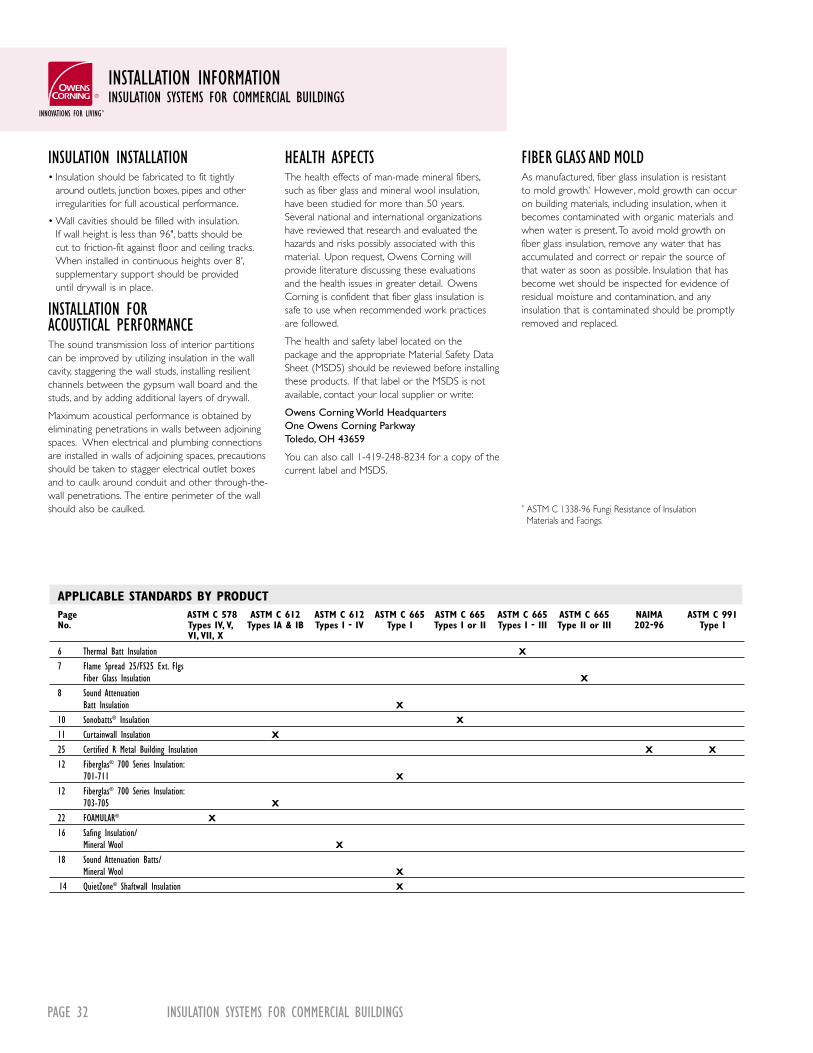
PAGE 32 INSULATION SYSTEMS FOR COMMERCIAL BUILDINGS
INSTALLATION INFORMATIONINSULATION SYSTEMS FOR COMMERCIAL BUILDINGS
INSULATION INSTALLATION• Insulation should be fabricated to fit tightly
around outlets, junction boxes, pipes and other irregularities for full acoustical performance.
• Wall cavities should be filled with insulation. If wall height is less than 96", batts should be cut to friction-fit against floor and ceiling tracks. When installed in continuous heights over 8', supplementary support should be provided until drywall is in place.
INSTALLATION FOR ACOUSTICAL PERFORMANCEThe sound transmission loss of interior partitions can be improved by utilizing insulation in the wall cavity, staggering the wall studs, installing resilient channels between the gypsum wall board and the studs, and by adding additional layers of drywall.
Maximum acoustical performance is obtained by eliminating penetrations in walls between adjoining spaces. When electrical and plumbing connections are installed in walls of adjoining spaces, precautions should be taken to stagger electrical outlet boxes and to caulk around conduit and other through-the-wall penetrations. The entire perimeter of the wall should also be caulked.
HEALTH ASPECTSThe health effects of man-made mineral fibers, such as fiber glass and mineral wool insulation, have been studied for more than 50 years. Several national and international organizations have reviewed that research and evaluated the hazards and risks possibly associated with this material. Upon request, Owens Corning will provide literature discussing these evaluations and the health issues in greater detail. Owens Corning is confident that fiber glass insulation is safe to use when recommended work practices are followed.
The health and safety label located on the package and the appropriate Material Safety Data Sheet (MSDS) should be reviewed before installing these products. If that label or the MSDS is not available, contact your local supplier or write:
Owens Corning World Headquarters One Owens Corning Parkway Toledo, OH 43659
You can also call 1-419-248-8234 for a copy of the current label and MSDS.
FIBER GLASS AND MOLDAs manufactured, fiber glass insulation is resistant to mold growth.* However , mold growth can occur on building materials, including insulation, when it becomes contaminated with organic materials and when water is present. To avoid mold growth on fiber glass insulation, remove any water that has accumulated and correct or repair the source of that water as soon as possible. Insulation that has become wet should be inspected for evidence of residual moisture and contamination, and any insulation that is contaminated should be promptly removed and replaced.
* ASTM C 1338-96 Fungi Resistance of Insulation Materials and Facings.
APPLICABLE STANDARDS BY PRODUCT Page ASTM C 578 ASTM C 612 ASTM C 612 ASTM C 665 ASTM C 665 ASTM C 665 ASTM C 665 NAIMA ASTM C 991 No. Types IV, V, Types IA & IB Types I - IV Type I Types I or II Types I - III Type II or III 202-96 Type I VI, VII, X
6 Thermal Batt Insulation X 7 Flame Spread 25/FS25 Ext. Flgs Fiber Glass Insulation X
8 Sound Attenuation Batt Insulation X 10 Sonobatts® Insulation X 11 Curtainwall Insulation X 25 Certified R Metal Building Insulation X X
12 Fiberglas® 700 Series Insulation: 701-711 X
12 Fiberglas® 700 Series Insulation: 703-705 X
22 FOAMULAR® X
16 Safing Insulation/ Mineral Wool X
18 Sound Attenuation Batts/ Mineral Wool X
14 QuietZone® Shaftwall Insulation X

www.owenscorning.com 1-800-GET-PINK PAGE 33
ATTACHMENT SYSTEMSINSULATION SYSTEMS FOR COMMERCIAL BUILDINGS
The friction-fit characteristics of Owens Corning glass fiber insulation batts frequently let you install them without additional support. However, many applications of fiber glass and FOAMULAR®
insulation products do require support to maintain insulation position. The following list is supplied as a convenience to readers interested in learning more about attachment systems.
ATTACHMENT SYSTEMS
COMPANY PRODUCT TELEPHONE
Handheld Power Fastening Tools
Pneumatic Nailers and Staplers
Stanley Bostitch TU20-7, RN45B 1-800-556-6696 Linic Systems HT-550, HT-755 1-800-513-9918 Paslode 3150W16R, 3200W16 1-800-222-6990 Pneutek PT-79, PT-250, PT-300-I 1-800-431-8665 Senco PW, SJ10 1-800-543-4596 Spotnails HL1620, HL7616AP 1-800-873-2239
Powder Actuated Systems
Hilti DX-600N, XA41-X-AM72 1-800-879-8000 Pneutek FA-75, SA-45, SA-75W 1-800-431-8665 ITW Ramset/Red Head D60, SA270, 721, D45 1-800-348-3231
Anchor Pins, Washers, Caps and Clips
AGM Industries Tactoo Insul-Hangers, Series T and Series TSA 1-800-225-9990 Buildex Tapcon Concrete Fastening Systems, 1-800-848-5611 HWH Teks/3, Gridmate Gemco Insulation Hangers, Self Locking Washers 1-800-331-1164 Cupped Head Weld Pins, Weld Pins Wind-lock Products Steel Screws, Steel/Plastic Washers 1-800-872-5625
Wire and Insulation Supports
Moore Products Insulation Support Rods and Netting 1-800-241-5807
Adhesives
OSI Sealants PL 200, PL Premium 1-800-624-7767 Foster & Childers Products Max Bond, 85-15, 85-120, 85-60 1-800-231-9541 CP-56, CP-82, CP-85, CP-88, CP-89, CP-35 Macco Adhesives LN-601, LN-604, Liquid Nails 1-800-634-0015 Tacc International MA-4062, DSA-40, PF-101 1-800-503-6991 3M Fastbond 42 NF Plus, 847L, 1357, 1-800-362-3550 1870, 1300L Gemco Tuff-Bond 1-800-331-1164
This list is supplied for the reader’s convenience. Owens Corning does not endorse or recommend these products. Contact the manufacturer for information on products and approved applications.

PAGE 34 INSULATION SYSTEMS FOR COMMERCIAL BUILDINGS
SECTION 07200EXTERIOR WALL THERMAL INSULATION
PART 1 GENERAL1.01 Summary A. Provide glass fiber thermal insulation for
exterior walls as indicated in building plans.1.02 Materials Provided in Other Sections A. Section 03400–Precast Concrete
B. Section 04200–Unit Masonry
C. Section 04235–Preassembled Masonry Panels
D. Section 04400–Stone
E. Section 07240–Exterior Insulation and Finish Systems
F. Section 07410–Preformed Roof and Wall Panels
G. Section 07420–Composite Building Panels
H. Section 07920–Sealants, Caulking and Seals
I. Section 08400–Entrances and Storefronts
J. Section 08500–Metal Windows
K. Section 08810–Glass
L. Section 08900–Glazed Curtain Walls
M. Section 09300–Tile1.03 References A. American Society for Testing and Materials
(ASTM).
1. E 84 Test Method for Surface Burning Characteristics of Building Materials
2. E 96 Test Method for Water Vapor Transmission of Materials
3. E 136 Test Method for Behavior of Materials in a Vertical Tube Furnace at 750˚C.
4. C 177 Test Method for Steady-State Thermal Transmission Properties by means of the Guarded Hot Plate
5. C 423 Test Method for Sound Absorption and the Sound Absorption Coefficient by the Reverberation Room Method
6. C 518 Test Method for Steady-State Thermal Transmission Properties by Means of the Heat Flow Meter
7. C 553 Standard Specification for Mineral Fiber Blanket and Felt Insulations
8. C 612 Standard Specification for Mineral Fiber Block and Board Thermal Insulation
9. C 665 Specification for Mineral Fiber Blanket Thermal Insulation for Light Frame Construction and Manufactured Housing
1.04 Submittals A. Product Data: Submit Owens Corning product
literature, samples and installation instructions for specified insulation.
1.05 Delivery A. Protect insulation from physical damage and
from becoming wet, soiled, or covered with ice or snow. Comply with manufacturer’s recommendations for handling, storage and protection during installation.
B. Label insulation packages to include material name, production date and/or product code.
C. Deliver and store materials under provision of Section (01600) (01620).
1.06 Limitations A. Do not use unfaced insulation in exposed appli-
cations where there is potential for skin contact and irritation.
B. Kraft and standard foil facings will burn and must not be left exposed. The facing must be installed in substantial contact with an approved exterior wall construction material. Protect facing from any open flame or heat source.
PART 2 PRODUCTS2.01 Manufacturer A. Owens Corning.2.02 Curtainwall CW225 Insulation A. Type: Unfaced or FRK-faced glass fiber thermal
insulation complying with ASTM C 612, Type 1A and 1B.
B. Size: R-value ____ When tested in accordance with ASTM C 518. Thickness___ Width___ Length ____
C. Vapor Retarder Perm Rating: FRK-facing Perms Maximum 0.10 When tested in accordance with ASTM E 96.
D. Surface Burning Characteristics:
1. Unfaced Insulation
Maximum flame spread: 20
Maximum smoke developed: 20
2. FRK-faced Insulation
Maximum flame spread: 25
Maximum smoke developed: 50
When tested in accordance with ASTM E 84.
E. Noise Reduction Coefficient:
1. Unfaced 2" NRC 1.00
2. FRK-faced 2" NRC 0.80
When tested in accordance with ASTM C 423 on a Type E-405 mounting.
F. Dimensional Stability:
Linear shrinkage less than 0.1%2.03 700 Series Insulation A. Type: 701 Unfaced glass fiber thermal insula-
tion complying with ASTM C 553, Type III and ASTM C 665, Type I.
B. Type: 711 Unfaced glass fiber thermal insula-tion complying with ASTM C 553, Type III and ASTM C 665, Type I.
C. Type: 703 Unfaced, FRK-faced and ASJ-faced glass fiber thermal insulation complying with ASTM C 612, Type 1A and 1B.
D. Type: 705 Unfaced, FRK-faced and ASJ-faced glass fiber thermal insulation complying with ASTM C 612, Type 1A and 1B.
E. Size: R-value ____
When tested in accordance with ASTM C 518. Thickness____ Width____ Length ____
F. Vapor Retarder Perm Rating:
1. FRK-facing Perms Maximum 0.02
2. ASJ-facing Perms Maximum 0.02
When tested in accordance with ASTM C 1136.
G. Surface Burning Characteristics:
Maximum flame spread: ____
Maximum smoke developed: ____
When tested in accordance with ASTM E 84.
H. Noise Reduction Coefficient: NRC ____
When tested in accordance with ASTM C 423 on a Type A mounting.
I. Dimensional Stability
Linear shrinkage less than 0.1%2.04 Flame Spread 25 Insulation A. Type: FRK-faced glass fiber thermal insulation
complying with ASTM C 665, Type III, Class A.
B. Size: Metal Frame Insulation R-value ____
When tested in accordance with ASTM C 518. Thickness____ Width____ Length ____
Wood Frame Insulation R-value ____
When tested in accordance with ASTM C 518.
Thickness____ Width____ Length ____ Special Application Insulation R-value ____
When tested in accordance with ASTM C 518. Thickness____ Width____ Length ____
C. Vapor Retarder Perm Rating:
FRK-facing Perms Maximum 0.10
When tested in accordance with ASTM E 96.
D. Surface Burning Characteristics:
Maximum flame spread: 25
Maximum smoke developed: 50
When tested in accordance with ASTM E 84.

www.owenscorning.com 1-800-GET-PINK PAGE 35
E. Combustion Characteristics: Classified non-combustible by model building codes.
F. Dimensional Stability: Linear shrinkage less than 0.1%
2.05 Thermal Batt Insulation A. Type: Unfaced glass fiber thermal insulation
complying with ASTM C 665, Type I and ASTM E 136.
B. Type: Kraft-faced glass fiber insulation complying with ASTM C 665, Type II, Class C.
C. Type: Foil-faced glass fiber thermal insulation complying with ASTM C 665, Type III, Class B and C.
D. Size: Metal Frame Insulation R-value ____
When tested in accordance with ASTM C 518.
Thickness____ Width____ Length ___ Wood Frame Insulation R-value ____
When tested in accordance with ASTM C 518.
Thickness____ Width____ Length ____
E. Vapor Retarder Perm Rating:
1. Foil-facing Perms Maximum 0.50
2. Kraft-facing Perms Maximum 1.00
When tested in accordance with ASTM E 96.
F. Surface Burning Characteristics:
1. Unfaced Insulation
Maximum flame spread: 10
Maximum smoke developed: 10
2. Foil-Faced Insulation
Maximum flame spread: 75
Maximum smoke developed: 150 When tested in accordance with ASTM E 84.
Kraft and standard foil facings on this insulation will burn and must not be left exposed. The facing must be installed in substantial contact with an approved exterior wall construction material. Protect facing from any open flame or heat source.
G. Combustion Characteristics:
Unfaced insulation passes ASTM E 136 test.
H. Dimensional Stability:
Linear shrinkage less than 0.1%2.06 Other Materials Provide materials, not specifically described but
required for a complete and proper installation of the work in this section.
PART 3 EXECUTION3.01 Inspection and Preparation A. Examine the areas and conditions under which
work of this section will be installed. Verify that adjacent materials are dry and ready to receive insulation. Verify mechanical and electrical services within walls have been tested.
B. Provide written report listing conditions detri-mental to performance of work in this section. Do not proceed with installation until unsatis-factory conditions have been corrected.
3.02 Installation—General A. Comply with manufacturer’s instruction for
particular conditions of installation in each case.
B. Mechanical Fasteners Apply insulation directly to the interior surface of the exterior wall with appropriate spindle or prong-type anchors.
• Fasten anchors to wall by welding the pin to metal and then impale the insulation, or by using pre-attached heads and welding them through the insulation.
• Fasten anchors to wall with adhesive. Follow manufacturer’s recommendations for surface preparation and adhesive pattern.
• Impale insulation on anchor and secure with washer. Select pin lengths to ensure tight fit. Protect pin tips where subject to human contact. See manufacturer’s diagram for impaling pin pattern.
C. Adhesive Fasteners Apply insulation with adhesives. Follow adhesive manufacturer’s recommendations for surface preparation and adhesive pattern.
D. Furring Strips
• Install insulation between furring strips, hat channels, or Z-shaped furring in areas where finish surface will be applied.
• Contact the furring strip manufacturer for recommendations on the appropriate fastener system to use.
E. Between Metal Studs
Friction-fit insulation between studs after cover material has been installed on one side of the cavity. Use wire or metal straps to hold insulation in place in applications without a cover material or where the stud depth is larger than the insulation thickness. When faced insulation is used, the attachment flanges may be taped to the face of the metal stud prior to applying the interior finish.
• Provide supplementary support to hold the product in place until finish surface is applied when insulation is installed in heights over 8 feet.
F. Between Wood Studs
Friction-fit unfaced insulation between studs after cover material has been installed on one side of the cavity. Use wire or metal straps to hold insulation in place in applications without a cover material. When faced insulation is used staple attachment flanges to face or side of stud every 8 to 12 inches to prevent gaps along the edge of the vapor retarder.
3.03 Installation—Vapor Retarders Maintain vapor retarder integrity by tightly
abutting adjacent insulation. Repair punctures or tears in vapor retarder facing by taping. Follow tape manufacturer’s application recommendations.
3.04 Material Storage and Protection
Protect insulation from damage and from becoming wet before, during and after installation.
SECTION 07200EXTERIOR WALL THERMAL INSULATION

BENEFITS FOR THE LIFE OF THE BUILDING.Maximize protection. Minimize noise. Owens Corning commercial building insulation products get the job done. Choose from a wide range of proven solutions for your unique needs, from energy-saving products that guard against the elements to the tools you need for noise reduction. You’ll feel and hear the difference.
OWENS CORNING WORLD HEADQUARTERS ONE OWENS CORNING PARKWAY TOLEDO, OHIO, USA 43659
1-800-GET-PINKwww.owenscorning.com
Pub. No. 17956-K. Printed in U.S.A. December 2004. THE PINK PANTHER™ & ©1964–2004 Metro-Goldwyn-Mayer Studios Inc. All Rights Reserved. The color PINK is a registered trademark of Owens Corning.©2004 Owens Corning.


