. Integrated Amplifier PM6006 Owner’s Manual You can print more than one page of a PDF onto a single sheet of paper. Contents Connections Playback Settings Tips Appendix 1 Front panel Rear panel Remote control unit Index
Transcript
.
Integrated AmplifierPM6006
Owner’s ManualYou can print more than one page of a PDF onto a single sheet of paper.
Accessories 4Inserting the batteries 5Operating range of the remote control unit 5
Features 6High quality sound 6High performance 6Easy operation 7
Part names and functions 8Front panel 8Rear panel 10Remote control unit 12
ConnectionsConnecting speakers 18
Speaker A/B connection 19Bi-wiring connection 20
Connecting a playback device 21Connecting a recording device 22Connecting a TV/Devices with digital audio connectors 23Connecting devices with remote control connectors 24
Performing operations by RC on this unit without visual contact 24Remotely connecting Marantz audio devices 24
Connecting the power cord 25
PlaybackTurning the power on 27Selecting the speakers for audio output 28Selecting the input source 28Adjusting the volume 28Turning off the sound temporarily (Muting) 28Adjusting the tone 28Playing CDs 29Connect and playback from a digital device (Coaxial/Optical) 30Recording 31
Turning Auto Standby mode on 33Turning Auto Standby mode off 33
Setting the remote signal receiving function 34Disabling the remote signal receiving function of the remotecontrol unit 34Enabling the remote signal receiving function of the remotecontrol unit 34
Setting remote control codes 35Setting remote control codes for the remote control 36Setting remote control codes for this unit 36
TipsTips 38Troubleshooting 39
AppendixD/A converter 43Explanation of terms 43Trademark information 44Specifications 45Index 48
Thank you for purchasing this Marantz product.To ensure proper operation, please read this owner’s manual carefully before using the product.After reading this manual, be sure to keep it for future reference.
AccessoriesCheck that the following parts are supplied with the product.
FeaturesHigh quality sound0 All-discrete current feedback amplifier
This unit uses a high-speed current feedback amplifier circuit for itspreamplifier and power amplifier so that signals from the Super AudioCD player can be amplified with high fidelity. The high-speed currentfeedback amplifier reproduces a natural sound space.
0 High-power outputThis unit features a slimline body, but comes with a large power supplyunit for dynamic music reproduction with high power.
0 High quality audio designThis unit has a high quality audio design such as minimized signal path,use of high sound quality parts, and large power circuit, which ispossible only in discrete audio components.
0 Phono input connectors for connecting turntablesThis unit is provided with a phono amplifier so that you can directlyconnect a turntable and play records (Only the MM cartridge can beused) (v p. 21)
0 Two-sets of speaker output terminalsIn addition to using two sets of speakers (Speakers A and Speakers B),you can connect to bi-wiring speakers with separate input terminals forhigh range and low range. (v p. 20)The unit adopts screw terminals that can connect thick audio cables.
High performance0 Digital Input (Coaxial, Optical 1/2)
This unit has a digital input terminal that allows input of digital audiofrom external devices such as televisions. The digital-to-analogconverter is an important factor in the sound quality of digital audioinput. The Marantz Super Audio CD player uses the Cirrus LogicCS4398, which has an excellent reputation for high precision.
0 Tone control functionThis unit has a tone control function for adjustment of bass (lowfrequency) and treble (high frequency) sound to produce your preferredtone. (v p. 29)
0 LOUDNESS functionThis unit is provided with a LOUDNESS function that makes it easier tohear music played back at a low volume level. (v p. 29)
Easy operation0 Remote control compatible with CD players and network audio
playersThe remote control provided with this unit can control Marantz CDplayers and network audio players in addition to this unit. (v p. 13)This unit can also switch between three remote control codes. Whenusing three units in the same area, you can set a different remotecontrol code for each unit to control them independently. (v p. 36)
A Power operation button (X)This turns the power on/off. (v p. 27)
B Power indicatorThis is lit as follows according to the power status:0 Power on : Off0 Standby : Red0 Power off : Off0 When the protection circuit is activated : Red (blinking)
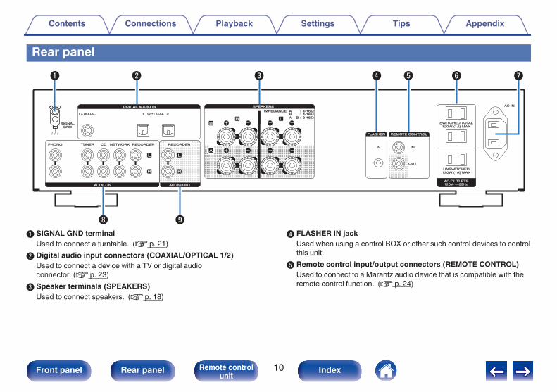
A SIGNAL GND terminalUsed to connect a turntable. (v p. 21)
B Digital audio input connectors (COAXIAL/OPTICAL 1/2)Used to connect a device with a TV or digital audioconnector. (v p. 23)
C Speaker terminals (SPEAKERS)Used to connect speakers. (v p. 18)
D FLASHER IN jackUsed when using a control BOX or other such control devices to controlthis unit.
E Remote control input/output connectors (REMOTE CONTROL)Used to connect to a Marantz audio device that is compatible with theremote control function. (v p. 24)
F AC outlets (AC OUTLETS)Used to connect the AC outlets of this unit in order to supply power toother AV equipment. (v p. 25)
G AC inlet (AC IN)Used to connect the power cord. (v p. 25)
H Analog audio input connectors (AUDIO IN)Used to connect devices equipped with analog audio outputconnectors.0 “Connecting a playback device” (v p. 21)0 “Connecting a recording device” (v p. 22)
I AUDIO OUT connectors (RECORDER)Used to connect the input connector of a recorder. (v p. 22)
o CD player operationsThe supplied remote control can be used to control a Marantz CD player inaddition to this unit. To operate a Marantz CD player, press the REMOTEMODE CD button to switch the remote control to the CD player operationmode.0 REMOTE MODE CD button lights for approximately two seconds.A POWER button (X)B Remote mode select button (REMOTE MODE CD)C System buttons
D Input source select button (INPUT)E Information button (INFO)F TIME buttonG Cursor buttons (uio p)H Program button (PROG)I Number buttons (0 – 9)J DIMMER buttonK RANDOM button (P)
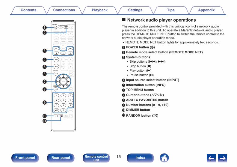
o Network audio player operationsThe remote control provided with this unit can control a network audioplayer in addition to this unit. To operate a Marantz network audio player,press the REMOTE MODE NET button to switch the remote control to thenetwork audio player operation mode.0 REMOTE MODE NET button lights for approximately two seconds.A POWER button (X)B Remote mode select button (REMOTE MODE NET)C System buttons
D Input source select button (INPUT)E Information button (INFO)F TOP MENU buttonG Cursor buttons (uio p)H ADD TO FAVORITES buttonI Number buttons (0 – 9, +10)J DIMMER buttonK RANDOM button (P)
o ContentsConnecting speakers 18Connecting a playback device 21Connecting a recording device 22Connecting a TV/Devices with digital audio connectors 23Connecting devices with remote control connectors 24Connecting the power cord 25
NOTE0 Do not plug in the power cord until all connections have been completed.0 Do not bundle power cords together with connection cables. Doing so can result in
humming or noise.
o Cables used for connectionsProvide necessary cables according to the devices you want toconnect.
0 Disconnect this unit’s power plug from the power outlet before connecting thespeakers.
0 Connect so that the speaker cable core wires do not protrude from the speakerterminal. The protection circuit may be activated if the core wires touch the rearpanel or if the + and - sides touch each other. (“Protection circuit” (v p. 43))
0 Never touch the speaker terminals while the power cord is connected. Doing socould result in electric shock.
0 Use speakers with impedances within the ranges shown below to suit how theyare used.Speaker terminalsused on this unit
No. of connectedspeakers
SpeakerImpedance
SPEAKERS A(Standard
connection)2 (one set) 4 – 16 Ω/ohms
SPEAKERS B 2 (one set) 4 – 16 Ω/ohmsSPEAKERS A and
SPEAKERS B 4 (two sets) 8 – 16 Ω/ohmsSPEAKERS A and
SPEAKERS B(Bi-wiring
connection)2 (one set) 4 – 16 Ω/ohms
o Connecting the speaker cablesCarefully check the left (L) and right (R) channels and + (red) and – (black)polarities on the speakers being connected to this unit, and be sure toconnect the channels and polarities correctly.
1 Peel off about 3/8 inch (10 mm) of sheathing from thetip of the speaker cable, then either twist the core wiretightly or terminate it.
.2 Turn the speaker terminal counterclockwise to loosen it.
.3 Insert the speaker cable’s core wire to the hilt into thespeaker terminal.
.4 Turn the speaker terminal clockwise to tighten it.
Speaker A/B connectionThis unit is equipped with two sets of speaker terminals (SPEAKER A and SPEAKER B). One set of speakers can be connected to each set of terminals,and a total of two sets of speakers can be connected.The same signal is output from the SPEAKERS A and SPEAKERS B terminals.When only one set of speakers is to be connected, use either the SPEAKERS A or SPEAKERS B terminals.
Bi-wiring connectionThis connection limits the effects of signal interference between the high range speakers (tweeters) and low range speakers (woofers), allowing you toenjoy high quality playback.When bi-wiring with bi-wireable speakers, connect the mid and high range terminals to SPEAKERS A (or SPEAKERS B), the low range terminals toSPEAKERS B (or SPEAKERS A).
.
w q
w q
HIGH
LOW
w q
w q
HIGH
LOW
Speaker (R)
Speaker (L)
Remove shorting bar Remove shorting bar Remove shorting bar Remove shorting bar
Connecting a playback deviceYou can connect turntables, tuners, CD players and network audio players to this unit.This unit is compatible with turntables equipped with a moving magnet (MM) phono cartridge. When you connect to a turntable with a low output movingcoil (MC) cartridge, use a commercially available MC head amp or a step-up transformer.If you set this unit’s input source to “PHONO” and you accidentally increase the volume without having a turntable connected, you may hear a hum noisefrom the speakers.
.
GNDAUDIOOUT
L
R
AUDIOOUT
LR
AUDIOOUT
LR
AUDIOOUT
LR
L
L
R
R
L
L
R
R
L
L
R
R
Network audio playerTuner
Turntable
CD player
NOTE0 The earth terminal (SIGNAL GND) of this unit is not for safety grounding purposes. If this terminal is connected when there is a lot of noise, the noise can be reduced. Note
that depending on the turntable, connecting the ground line may have the reverse effect of increasing noise. In this case, it is not necessary to connect the ground line.
Connecting a TV/Devices with digital audio connectorsUse this connection to input digital audio signals to this unit, and convert the signals for playback using the D/A converter of this unit. (v p. 30)
.
OPTICALOUT
COAXIALOUT
TV / Satellite receiver etc.
NOTE0 Linear PCM signals with a sampling frequency of 32 kHz, 44.1 kHz, 48 kHz, 88.2 kHz, 96 kHz, 176.4 kHz, or 192 kHz can be input into this device.0 Do not input non-PCM signals, such as DTS and AAC. This causes noise and could damage the speakers.
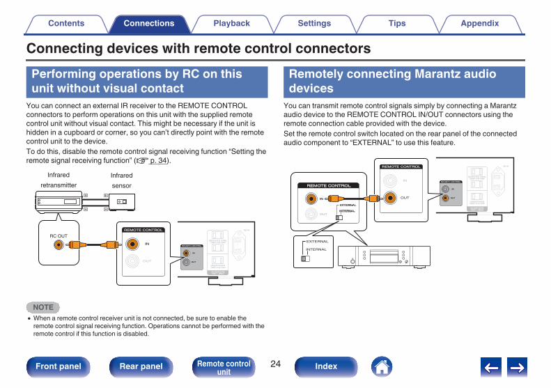
Connecting devices with remote control connectorsPerforming operations by RC on thisunit without visual contact
You can connect an external IR receiver to the REMOTE CONTROLconnectors to perform operations on this unit with the supplied remotecontrol unit without visual contact. This might be necessary if the unit ishidden in a cupboard or corner, so you can’t directly point with the remotecontrol unit to the device.To do this, disable the remote control signal receiving function “Setting theremote signal receiving function” (v p. 34).
.
RC OUT
Infrared retransmitter
Infrared sensor
NOTE0 When a remote control receiver unit is not connected, be sure to enable the
remote control signal receiving function. Operations cannot be performed with theremote control if this function is disabled.
Remotely connecting Marantz audiodevices
You can transmit remote control signals simply by connecting a Marantzaudio device to the REMOTE CONTROL IN/OUT connectors using theremote connection cable provided with the device.Set the remote control switch located on the rear panel of the connectedaudio component to “EXTERNAL” to use this feature.
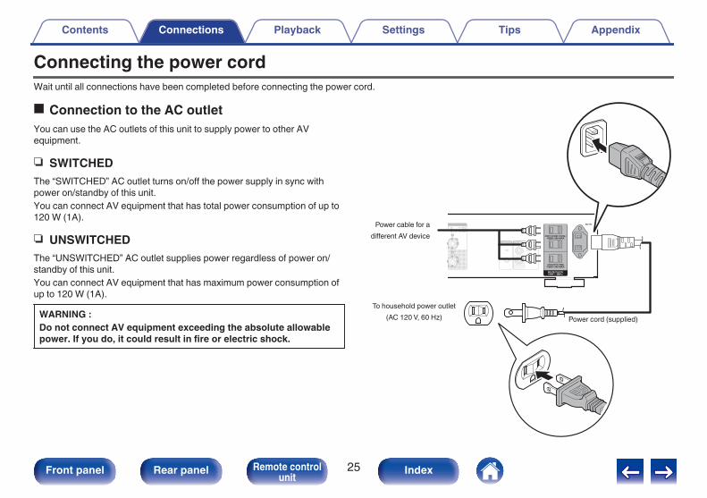
Connecting the power cordWait until all connections have been completed before connecting the power cord.
o Connection to the AC outletYou can use the AC outlets of this unit to supply power to other AVequipment.
n SWITCHEDThe “SWITCHED” AC outlet turns on/off the power supply in sync withpower on/standby of this unit.You can connect AV equipment that has total power consumption of up to120 W (1A).
n UNSWITCHEDThe “UNSWITCHED” AC outlet supplies power regardless of power on/standby of this unit.You can connect AV equipment that has maximum power consumption ofup to 120 W (1A).
WARNING :Do not connect AV equipment exceeding the absolute allowablepower. If you do, it could result in fire or electric shock.
o ContentsTurning the power on 27Selecting the speakers for audio output 28Selecting the input source 28Adjusting the volume 28Turning off the sound temporarily (Muting) 28Adjusting the tone 28Playing CDs 29Connect and playback from a digital device (Coaxial/Optical) 30Recording 31
1 Press X on the main unit to turn the power on.Input indicator for the selected source lights.
NOTE0 Turn VOLUME on the main unit to adjust the volume to the lowest level before
turning on the power.
o Switching the power to standby
1 Press AMP POWER X on the remote control.The power indicator lights in red.
0 Press AMP POWER X to turn on power from standby mode.0 You can turn the INPUT SELECTOR when the unit is in standby mode to turn on
the power.
NOTE0 Power continues to be supplied to some of the circuitry even when the power is in
the standby mode. When leaving home for long periods of time or when going onvacation, either press X on the main unit to turn off the power, or unplug the powercord from the power outlet.
Playing CDsThis section uses playback from a CD as an example.
1 Press X on this unit to turn the power on.
2 Press the input source select button (CD) to switch theinput source to “CD”.The “CD” input indicator lights.
3 Playback the CD.
4 Use VOLUME df to adjust the volume.
o Playback in source direct modeThe signal does not pass through the tone adjustment circuitry (BASS,TREBLE and BALANCE), resulting in playback of a higher soundquality.
1 Press SOURCE DIRECT to turn on source direct mode.The SOURCE DIRECT indicator lights.
o Playback in LOUDNESS modeWhen music is played at a low volume level, the effect of the bass andtreble cannot be heard easily. The LOUDNESS function corrects thebass and treble in these situations, allowing you to enjoy natural-sounding playback.
1 Press LOUDNESS to turn on LOUDNESS mode.The LOUDNESS indicator lights.
Connect and playback from a digitaldevice (Coaxial/Optical)
1 Connect digital device to this unit. (v p. 23)
2 Press the input source select button (COAXIAL orOPTICAL) to switch the input source to “COAXIAL” or“OPTICAL 1/2”.
3 Start playback of the digital device connected to thisunit.The COAXIAL or OPTICAL 1/2 input indicator flashes in blue if thisunit cannot detect the sampling frequency of the input signal.
4 Use VOLUME df to adjust the volume.
o Specifications of supported audio formatsSee “D/A converter” (v p. 43).
NOTE0 Do not input non-PCM signals, such as Dolby Digital, and DTS. This causes noise
and could damage the speakers.0 If the sampling frequency switches, such as from A mode to B mode in a CS
broadcast, muting may operate for 1 – 2 seconds, cutting the sound.
RecordingAudio signals input into this unit can be output to an external recordingdevice. When recording audio from a playback device connected to thisunit, audio can be recorded with the playback device still connected to thisunit.
1 Press X on this unit to turn the power on.
2 Press the input source select button to switch to theinput source from which you want to record.The indicator of the selected input source lights.
3 Recording starts.0 For information on operations, see the owner’s manual of the
Setting the Auto Standby modeYou can set the unit to automatically switch to standby mode if the unit isnot operated for 30 minutes when there is no audio input (Auto Standbymode).Auto Standby mode is set to off by default.
.
Power indicatorSOURCE DIRECT
Turning Auto Standby mode on
1 Press and hold SOURCE DIRECT for more than 5seconds to turn the Auto Standby mode on.The power indicator flashes three times.
Turning Auto Standby mode off
1 Press and hold SOURCE DIRECT for more than 5seconds to turn the Auto Standby mode off.The power indicator flashes once.
Setting the remote signal receiving functionWhen you connect a IR receiver (sold separately) to the REMOTECONTROL IN connector of this unit, use the following procedure todisable the remote signal receiving function of this unit. When the functionis enabled, you can not perform operations with the remote control unit.By default, this function is enabled.
.
SPEAKERS A SPEAKERS B
Disabling the remote signal receivingfunction of the remote control unit
1 Press SPEAKERS B for approximately 5 seconds todisable the remote control signal receiving function.The indicator of the currently set input source flashes in red threetimes.
Enabling the remote signal receivingfunction of the remote control unit
1 Press SPEAKERS A for approximately 5 seconds toenable the remote control signal receiving function.The “RECORDER” input indicator flashes in blue three times.
Remote control codes are set between this unit and the supplied remotecontrol. You can select one of the three types of remote control codes, andthe remote control can be used to control the unit when the same remotecontrol code is used. If three of these units are used in the same location,all three units can be controlled simultaneously using one remote controlin the default settings. By setting individual remote control codes betweena unit and the remote control, the remote control can be used to controlonly the unit that has the same remote control code.Be sure to check the operation of each unit after setting the remote controlcodes.The default setting is “AMP1”.
Setting remote control codes for theremote controlo To set the remote control codes to AMP2
1 Hold down REMOTE MODE CD and the number 2button for more than 5 seconds.
o To set the remote control codes to AMP3
1 Hold down REMOTE MODE CD and the number 3button for more than 5 seconds.
0 To return the remote control code to the default setting, hold down REMOTEMODE CD and the number 1 button for more than 5 seconds.
NOTE0 The remote control codes returns to the default settings when the batteries are
removed. Set the remote control codes again after replacing the batteries.
Setting remote control codes for thisunit
1 Point the remote control for which the remote controlcode was set at this unit, and press REMOTE MODE CDand ENTER.The input indicators on the unit flash as shown below according tothe set remote control code.
Remote controlcodes Input indicatorAMP 1 PHONO indicator flashes three timesAMP 2 CD indicator flashes three timesAMP 3 NETWORK indicator flashes three times
o ContentsTipsI want to play back high quality television sound 38I want to adjust the tone myself 38I want sound playback that is faithful to the original sound 38I want to hear music that is close to the original sound quality at lowvolume 38I want to operate a Marantz CD player or network audio player usingthe remote control of this unit 38I want to use more than one unit in one location 38
TroubleshootingPower does not turn on / Power is turned off 39Operations cannot be performed through the remote control unit 40No sound comes out 41Desired sound does not come out 41Sound is interrupted or noise occurs 42
TipsI want to play back high quality television sound0 Connect the digital audio output connector of the TV to the digital audio input connector (COAXIAL or OPTICAL 1/2) of this unit, and switch the input
source to the connected (COAXIAL or OPTICAL 1/2) connector. (v p. 23)0 This unit can play back 2 channel linear PCM digital audio signals.I want to adjust the tone myself0 Use the BASS, TREBLE and BALANCE knobs to adjust the sound as desired. (v p. 28)I want sound playback that is faithful to the original sound0 Set the Source Direct mode on. (v p. 29)I want to hear music that is close to the original sound quality at low volume0 Turn the LOUDNESS mode on. (v p. 29)I want to operate a Marantz CD player or network audio player using the remote control of this unit0 Switch the remote control operating mode. (“CD player operations” (v p. 13), “Network audio player operations” (v p. 15))0 Also refer to the CD player or network audio player instruction manuals.I want to use more than one unit in one location0 Set individual remote control codes for each combination of devices and remote control. (v p. 36)
TroubleshootingIf a problem should arise, first check the following:1. Are the connections correct?2. Is the set being operated as described in the owner’s manual?3. Are the other devices operating properly?If this unit does not operate properly, check the corresponding symptoms in this section.If the symptoms do not match any of those described here, consult your dealer as it could be due to a fault in this unit. In this case, disconnect the powerimmediately and contact the store where you purchased this unit.
o Power does not turn on / Power is turned offSymptom Cause / Solution Page
Power is not turned on. 0 Check whether the power plug is correctly inserted into the power outlet. 25Power automatically turnsoff.
0 The Auto Standby mode is on. When approx. 30 minutes pass with no audio input and no operations onthe unit, this unit automatically enters the standby mode. To turn off the Auto Standby mode, press theSOURCE DIRECT button for 5 seconds or longer.
33
Power turns off and thepower indicator flashes inred approx. every 0.25seconds.
0 The protection circuit has been activated due to a rise in temperature within this unit. Turn the power off,wait about an hour until this unit cools down sufficiently, and then turn the power on again.
43
0 Please re-install this unit in a place having good ventilation. -
0 Check the speaker connections. The protection circuit may have been activated because speaker cablecore wires came in contact with each other or a core wire was disconnected from the connector andcame in contact with the rear panel of this unit. After unplugging the power cord, take corrective actionsuch as firmly re-twisting the core wire or taking care of the connector, and then reconnect the wire.
18
0 Turn down the volume and turn on the power again. 270 This unit’s amplifier circuit has failed. Unplug the power cord and contact our customer service center. -
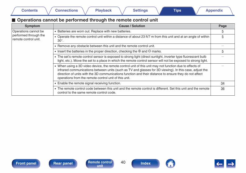
o Operations cannot be performed through the remote control unitSymptom Cause / Solution Page
Operations cannot beperformed through theremote control unit.
0 Batteries are worn out. Replace with new batteries. 50 Operate the remote control unit within a distance of about 23 ft/7 m from this unit and at an angle of within
30°.5
0 Remove any obstacle between this unit and the remote control unit. -
0 Insert the batteries in the proper direction, checking the q and w marks. 50 The set’s remote control sensor is exposed to strong light (direct sunlight, inverter type fluorescent bulb
light, etc.). Move the set to a place in which the remote control sensor will not be exposed to strong light.-
0 When using a 3D video device, the remote control unit of this unit may not function due to effects ofinfrared communications between units (such as TV and glasses for 3D viewing). In this case, adjust thedirection of units with the 3D communications function and their distance to ensure they do not affectoperations from the remote control unit of this unit.
-
0 Enable the remote signal receiving function. 340 The remote control code between this unit and the remote control is different. Set this unit and the remote
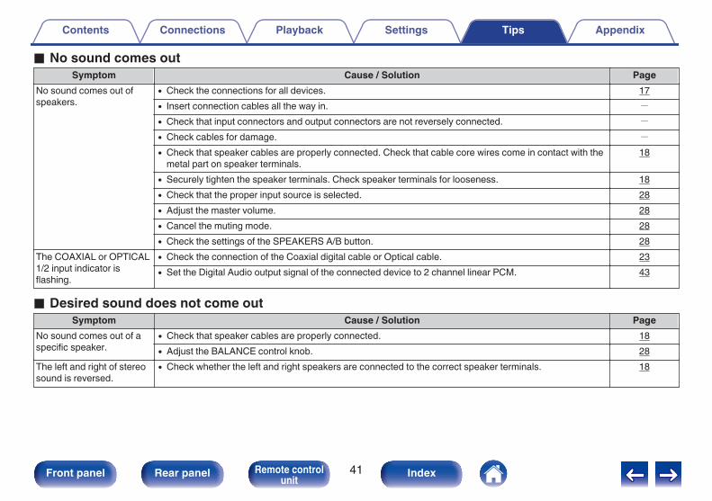
0 Check the connections for all devices. 170 Insert connection cables all the way in. -
0 Check that input connectors and output connectors are not reversely connected. -
0 Check cables for damage. -
0 Check that speaker cables are properly connected. Check that cable core wires come in contact with themetal part on speaker terminals.
18
0 Securely tighten the speaker terminals. Check speaker terminals for looseness. 180 Check that the proper input source is selected. 280 Adjust the master volume. 280 Cancel the muting mode. 280 Check the settings of the SPEAKERS A/B button. 28
The COAXIAL or OPTICAL1/2 input indicator isflashing.
0 Check the connection of the Coaxial digital cable or Optical cable. 230 Set the Digital Audio output signal of the connected device to 2 channel linear PCM. 43
o Desired sound does not come outSymptom Cause / Solution Page
No sound comes out of aspecific speaker.
0 Check that speaker cables are properly connected. 180 Adjust the BALANCE control knob. 28
The left and right of stereosound is reversed.
0 Check whether the left and right speakers are connected to the correct speaker terminals. 18
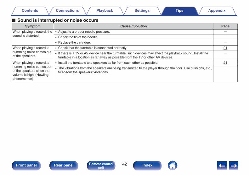
o Sound is interrupted or noise occursSymptom Cause / Solution Page
When playing a record, thesound is distorted.
0 Adjust to a proper needle pressure. -
0 Check the tip of the needle. -
0 Replace the cartridge. -
When playing a record, ahumming noise comes outof the speakers.
0 Check that the turntable is connected correctly. 210 If there is a TV or AV device near the turntable, such devices may affect the playback sound. Install the
turntable in a location as far away as possible from the TV or other AV devices.-
When playing a record, ahumming noise comes outof the speakers when thevolume is high. (Howlingphenomenon)
0 Install the turntable and speakers as far from each other as possible. 210 The vibrations from the speakers are being transmitted to the player through the floor. Use cushions, etc.,
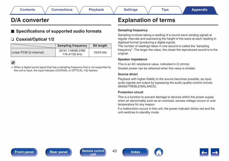
D/A convertero Specifications of supported audio formatsn Coaxial/Optical 1/2
Sampling frequency Bit lengthLinear PCM (2-channel) 32/44.1/48/88.2/96/
176.4/192 kHz 16/24 bits
0 When a digital sound signal that has a sampling frequency that is not supported bythis unit is input, the input indicator (COAXIAL or OPTICAL 1/2) flashes.
Explanation of termsSampling frequencySampling involves taking a reading of a sound wave (analog signal) atregular intervals and expressing the height of the wave at each reading indigitized format (producing a digital signal).The number of readings taken in one second is called the “samplingfrequency”. The larger the value, the closer the reproduced sound is to theoriginal.Speaker impedanceThis is an AC resistance value, indicated in Ω (ohms).Greater power can be obtained when this value is smaller.Source directPlayback with higher fidelity to the source becomes possible, as inputaudio signals are output by bypassing the audio quality-control circuits(BASS/TREBLE/BALANCE).Protection circuitThis is a function to prevent damage to devices within the power supplywhen an abnormality such as an overload, excess voltage occurs or overtemperature for any reason.If a malfunction occurs in this unit, the power indicator blinks red and theunit switches to standby mode.
Adobe, the Adobe logo and Reader are either registered trademarks ortrademarks of Adobe Systems Incorporated in the United States and/orother countries.
Auto Standby mode ........................................ 33
v BBALANCE ...................................................... 28BASS ............................................................. 28
v CCD player ................................................. 21, 29
v IInput source ................................................... 28
v LLOUDNESS mode ......................................... 29
v MMuting ............................................................ 28
v NNetwork audio player ..................................... 21
v PProtection circuit ............................................ 43
v RRecording device ........................................... 22Remote control ............................................... 24Remote control codes settings ....................... 36Remote control unit ........................................ 12
v SSource direct ............................................ 29, 43Speaker impedance ....................................... 43Speakers ........................................................ 18Speaker (Bi-wiring) connection ...................... 20