Page 1
Modern Methods in Heterogeneous Catalysis ResearchFritz Haber Institute, Berlin, 24 November 2006
Dr. Techn. Liisa Rihko-StruckmannMax-Planck-Institute for Dynamics of Complex Technical Systems
Sandtorstraße 1, 39106 Magdeburg, Germany
[email protected]
Integrated Catalytic ProcessesIntegrated Catalytic Processes
Page 2
Integrated Catalytic Processes –Lecture Outline
Modern Methods in Heterogeneous Catalysis ResearchFritz Haber Institute, Berlin, 24 November 2006
Reactive Distillation
Periodic Separating Reactors
Process Intensification
Membrane ReactorsFuel Cells
Page 3
see: A.I. Stankiewicz, J.A. Moulijn, Chem. Eng. Progress, Jan. 2000, 22-34
Process Intensification
Equipment Methods
Process Intensification
• innovative methods and technologiesthe efficiency of chemical processes
• rethinking a process as a whole complex
Page 4
Potential of Integrated Catalytic Processes
Synergetic interactions of chemical and physicalunit operations may lead to:
increase of productivity from process intensification
increase of selectivity of reactions and/or separations
improve separation by „reacting away“ azeotropic mixtures
more efficient (in situ) use of energy
inherent safety
improved environmental compatibility(e.g. by avoidance of by-products and hazardous solvents).
Page 5
Integration of Unit Operations in Multifunctional Reactors
PretreatmentOperations
(Phys./Chem.)
Chemical/CatalyticBiological
Units
Raw Materials
Purification/Separation
Units forReactants
By-Products
Purification/SeparationUnits for
By-Products
Main Products
MultifunctionalReactors (e.g. Reactive Mill)
Multifunctional Reactors(Reactive Distillation / Absorption / Extraction / Adsorption Column)
MultifunctionalReactors (e.g. Fuel Cells)
Recycle
Page 6
Integrated Catalytic Processes –Lecture Outline
Modern Methods in Heterogeneous Catalysis ResearchFritz Haber Institute, Berlin, 24 November 2006
Reactive Distillation
Periodic Separating Reactors
Process Intensification
Membrane ReactorsFuel Cells
Page 7
Reactive Distillation
• Combination of a Reactor and a Distillation Unit
Product
FeedA
By-Product
Feed B
Reactive SectionStages(Catalyst)
RectifyingSection (6 Stages)
StrippingSection
Page 8
V LS
Vjxi,j
V
hjV
TjV
Lj-1xi,j-1
L
hj-1L
Tj-1L
Vj+1xi,j+1
V
hj+1V
Tj+1V
Ljxi,j
L
hjL
TjL
QjU
Qreb
Fm
α
R
j - 1j
j + 1
p
Modeling of Catalytic Distillation Column
PSEUDOHOMOGENEOUS MODEL+ V/L mass transfer model+ reaction microkinetics
HETEROGENEOUS MODEL(„Fully rate-based“)+ V/L mass transfer model+ reaction microkinetics+ intraparticle mass transfer
(Maxwell-Stefan-eqs.)
SPECIFICATIONS+ specifications: p, F, Relative volatility α, Q, R
Page 9
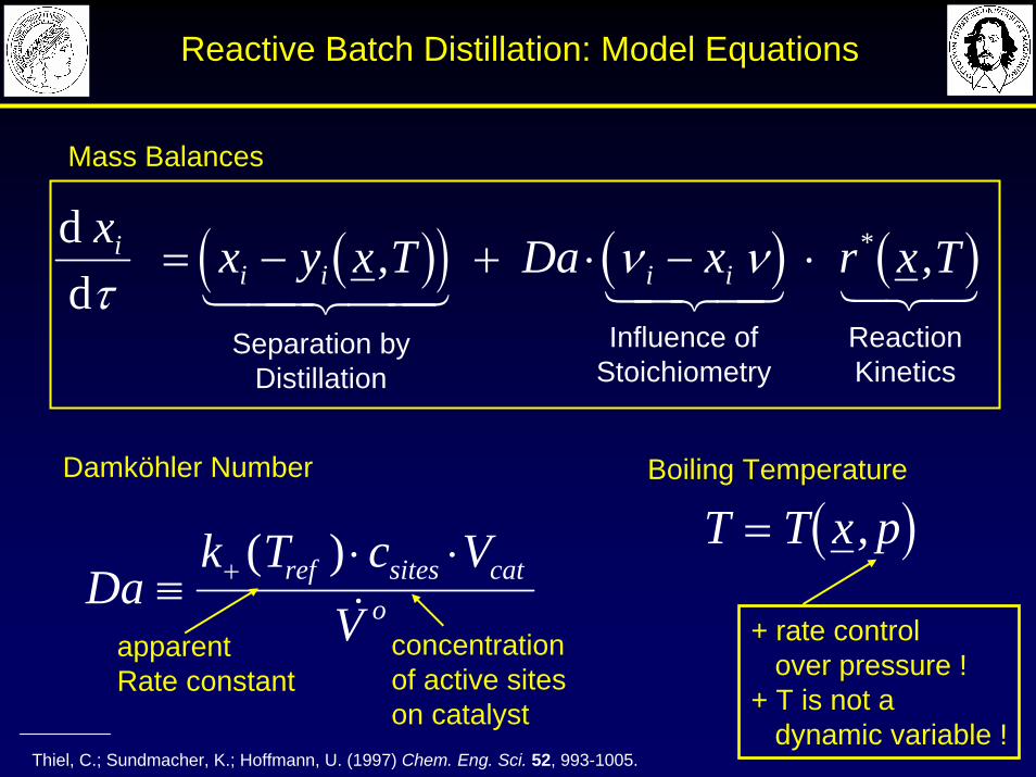
( )( ) ( ) ( )d d
x x y x T Da x r x Tii i i iτ
ν ν= − + ⋅ − ⋅, ,*
1 244 344 1 24 34 123Separation by
DistillationReactionKinetics
Influence ofStoichiometry
Dak T c V
Vref sites cat
o≡⋅ ⋅+ ( )&
Damköhler Number Boiling Temperature
( )T T x p= ,
Thiel, C.; Sundmacher, K.; Hoffmann, U. (1997) Chem. Eng. Sci. 52, 993-1005.
Reactive Batch Distillation: Model Equations
Mass Balances
+ rate controlover pressure !
+ T is not a dynamic variable !
apparent Rate constant
concentrationof active siteson catalyst
Page 10
Residue Curve Maps
• Liquid residue composition with time • 1-stage distillation (batch distillation) with no reflux
- the feasibility of separation of homogeneous mixtures(stages / energy !)
- the design and operation of a distillation column(azeotropic mixtures)
- equilibrium relationship of ternary mixures- bottom and overhead products
Example (ideal, no azeotropes) Starting mixture (t=0):•MeOH 0,6•EtOH 0,25•N-PrOH 0,15
Ethanol (78,3°C)
Methanol (64,6°C)
N-Propanol(93,1°C)
t=1t=0t=2
tfin
Residue line
Page 11
Reactive Batch Distillation: MeOH + IA ⇔ TAME
Thiel, C.; Sundmacher, K.; Hoffmann, U. (1997) Chem. Eng. Sci. 52, 993-1005.
Heating policy:V / V0 = H / H0
Liquid phase:Holdup HComposition xi
MeOHL + IAL TAMEL
MeOHV IAV TAMEV
Qreb
Vapour phase:Vapour Flow VComposition yi
FCR
LCRH+
Catalyst: Acidic Ion Exchange Resin (Vcat, cH+)
Page 12
p = 10 bar
2 stable nodes1 unstable node (azeotrope)1 saddle point (azeotrope)1 separatrix
Mol
e Fr
actio
nof
MeO
H
Mole Fraction IATAME IA
MeOH
Thiel, C.; Sundmacher, K.; Hoffmann, U. (1997) Chem. Eng. Sci. 52, 993-1005.
(373K)
(304K)
(359K)
Catalytic Batch Distillation for TAME-Synthesis: No Reaction (Da = 0)
distillation boundary
Page 13
Thiel, C.; Sundmacher, K.; Hoffmann, U. (1997) Chem. Eng. Sci. 52, 993-1005.
p = 10 bar
3 stable nodes0 unstable nodes2 saddle points2 separaticdschemical equilibrium line
Mol
enbr
uch
Met
hano
l
Molenbruch IsoamylenTAME IA
MeOH
Catalytic Batch Distillation for TAME-Synthesis: Slow Reaction (Da = 10-4)
Mol
e Fr
actio
nof
MeO
H
Mole Fraction of IA
distillation boundaries
Page 14
Thiel, C.; Sundmacher, K.; Hoffmann, U. (1997) Chem. Eng. Sci. 52, 993-1005.
Mole Fraction of IA TAME IA
MeOH2 stable nodes0 unstable nodes1 saddle point1 separatrixchemical equilibrium line
p = 10 bar
Catalytic Batch Distillation for TAME-Synthesis: Fast Reaction (Da = 10-3)
Mol
e Fr
actio
nof
MeO
H
distillation boundary
Page 15
Mol
enbr
uch
Met
hano
l
Molenbruch IsoamylenTAME IA
MeOH2 stabile nodes0 unstable nodes1 saddle point1 separatixchemical equilibrium line
p = 10 bar
Thiel, C.; Sundmacher, K.; Hoffmann, U. (1997) Chem. Eng. Sci. 52, 993-1005.
Catalytic Batch Distillation for TAME-Synthesis: Reaction in Equilibrium (Da > 1)
Mol
e Fr
actio
nof
MeO
H
Mole Fraction of IA
distillation boundary
Page 16
Main Rxn 2 B ⇔ A + CSide Rxn 2 C → 2 D
αAC = 10αBC = 3αDC = 13
20 stages
9 stages
9 stages
Feed at
stage 20
Variationof Da on
stage
Keq = 0.25R = 3.8
Studies of Side Reactions: Influence of Stage Damköhler Number
( ) ( )2
2*
2
2*
51 1.0
51/
C
C
sideC
eqCA B
main x x r
x Kx - xx
r+
=+
=
A + D
C
B
0,01 0,1 10,0
0,2
0,4
0,6
0,8
1,0
Selectivity, S
Conversion, X
Stage Damköhler Number, Da
N = 38
Page 17
5 stagesFeed at
stage 20
Da = 0.8 on stage
A + D
C
B
Studies of Side Reactions: Influence of Catalyst Position
Changing Positionof Catalyst
5 10 15 20 25 300,0
0,2
0,4
0,6
0,8
1,0Selectivity, S
Conversion, X
Position of Catalyst SectionN = 38
Main Rxn 2 B ⇔ A + CSide Rxn 2 C → 2 D
αAC = 10αBC = 3αDC = 13
Keq = 0.25R = 3.8
( ) ( )2
2*
2
2*
51 1.0
51/
C
C
sideC
eqCA B
main x x r
x Kx - xx
r+
=+
=
Page 18
Studies of Side Reactions: Influence of Catalyst Position(Da = 0.2, Reactive Stages = 5)
A + D
C
B
A + D
C
B
40
35
30
25
20
15
10
5
0
0,0 0,2 0,4 0,6 0,8 1,0
xi
Sta
ge
DA
B
C
40
35
30
25
20
15
10
5
0
0,0 0,2 0,4 0,6 0,8 1,0
xi
Sta
ge
D A
B
C
A + D
C
B
A + D
C
B
2
2
*
* /~
C
eqCA B
side
main
xKx - xx
rr2 B ⇔ A + C
2 C → 2 D
Page 19
Influence of Reflux Ratio on Conversion
Bessling, B.; Löning, J.M.; Ohligschläger, A.; Schembecker, G.; Sundmacher, K., Chem Eng. Technol. 21 (5), 393-400.
Conversion of Acetic Acid
Methyl Acetate
Acetic Acid
Water
Catalytic Section (ICVT-Rings)
Rectifying Section (Rombopak 9M)
Stripping Section (Rombopak 9M)
Methanol
Methyl Acetate
Acetic Acid
Water
Catalytic Section (ICVT-Rings)
Rectifying Section (Rombopak 9M)
Stripping Section (Rombopak 9M)
Methanol
There is an optimal reflux ratio !
Page 20
Multiple Steady States of TAME CD Column:Model Predictions and Experimental Results
Mohl, K.-D.; Kienle, A.; Gilles, E.-D.; Rapmund, P.; Sundmacher, K.; Hoffmann, U., Chem. Eng. Sci. 54 (1999) 1029-1043.
Experimental Liquid Phase TemperaturesModel Predictions
Col
umn
heig
ht, z
/ [m
]x T
AM
EB
/ [ -
]
Col
umn
heig
ht, z
/ [m
]
Temperature, T / [°C]
Heating Rate, Qreb / [kW]
Temperature, T / [K]
TIR10
TIR 5
Page 21
Relative Volatility, αH2O/Ester
Low HighMedium
Fast
Slow
Rea
ctio
nR
ate,
r
see e.g.: Schoenmakers (1997)
Mapping of Reactor-Separator Systems for Esterification: Alcohol + Acid ⇔ Ester + H2O
Page 22
Simple Guideline for CD Reactor Selection
Slow reactions: Da << 1
+ reaction kinetics is limiting+ high residence time+ hom. catalysis: high liquid holdup+ het. catalysis: high catalyst holdup
Solution
+ tray column (bubble caps)+ packed column with random packing+ column with external side reactors
Fast reactions: Da ≥ 1
+ mass transfer is limiting+ low residence time sufficient+ hom. catalysis: low liquid holdup+ het. catalysis: low catalyst holdup
Solution
+ packed column + tray column with low holdup
increase p
Page 23
Process Examples of Catalytic Distillation
Modern Methods in Heterogeneous Catalysis ResearchFritz Haber Institute, Berlin, 24 November 2006
Catalytic Distillation Processes
Page 24
Motives for Application of Reactive Distillation
Motives Examples
Overcoming Limitations Methanol + Acetic Acid ⇔ Methyl Acetate + H2Oof Chemical Equilibrium Methanol + Isobutene ⇔ Methyl-tert.-butylether (MTBE)
Formaldehyde + 2 Methanol ⇔ Methylal + H2O
Increase of Chlorohydrins → Propylene Oxide + H2O → Proplene GlycolSelectivity 2 Acetone → Diacetone Alcohol → Mesityl Oxide + H2O
Isobutane + 1-Butene → Isooctane + 1-Butene → C12H24
Use of Heat Propene + Benzene → Cumeneof Reaction Ethylene Oxide + H2O → Ethylene Glycol
Separation of m-Xylene / p-Xylene (Reactive Entrainer: Na-p-Xylene)Closely Boiling Mixtures Cyclohexene / Cyclohexane (Reactive Entrainer: Formic Acid)
1-Butene / Isobutene (Reactive Entrainer: Methanol / Water)
Breaking of Methyl Acetate / Water ; Methyl Acetate / MethanolAzeotropes (Entrainer: Acetic Acid)
High Purity Hexamethylene Diamine / Water (in Nylon 6,6 process)Separation (Reactive Entrainer: Adipic Acid)
Rea
ctio
nP
robl
ems
Sep
arat
ion
Pro
blem
s
See e.g.: Sundmacher, K., Rihko, L., Hoffmann, U., Chem. Eng. Commun. 127 (1994) 151-167.
Page 25
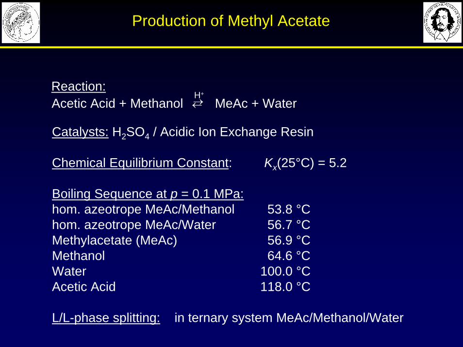
Production of Methyl Acetate
H+
Acetic Acid + Methanol MeAc + Water←→Reaction:
Catalysts: H2SO4 / Acidic Ion Exchange Resin
Chemical Equilibrium Constant: Kx(25°C) = 5.2
Boiling Sequence at p = 0.1 MPa:hom. azeotrope MeAc/Methanol 53.8 °Chom. azeotrope MeAc/Water 56.7 °CMethylacetate (MeAc) 56.9 °CMethanol 64.6 °C Water 100.0 °CAcetic Acid 118.0 °C
L/L-phase splitting: in ternary system MeAc/Methanol/Water
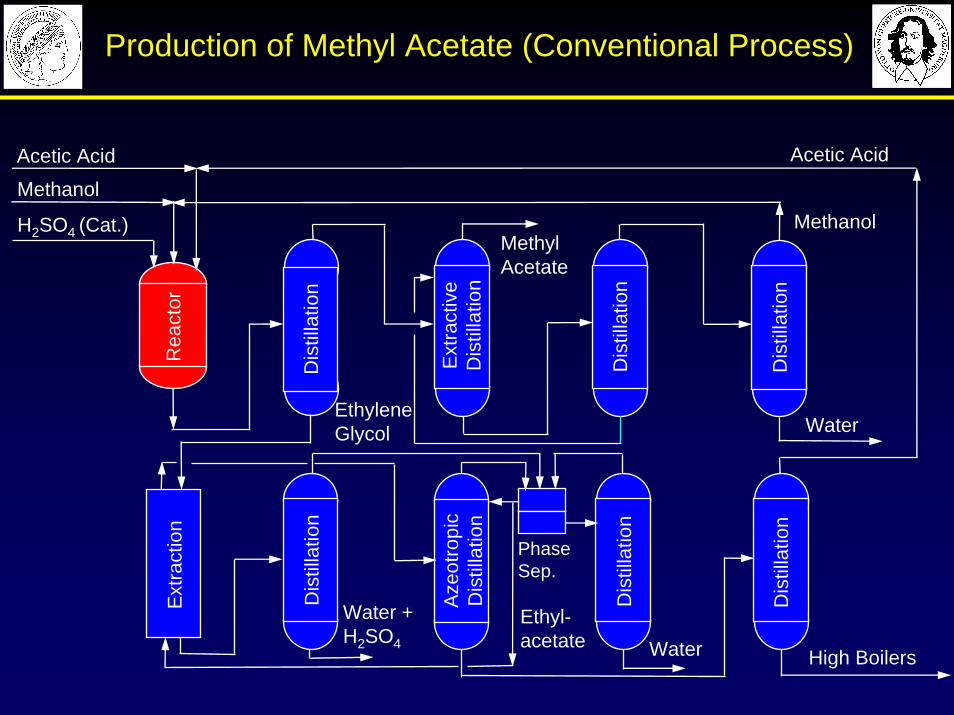
Page 26
Acetic Acid
Methanol
H2SO4 (Cat.)
Rea
ctor
MethylAcetate
High Boilers
Water +H2SO4
Ext
ract
ive
Dis
tilla
tion
Ext
ract
ion
Dis
tilla
tion
Aze
otro
pic
Dis
tilla
tion
Dis
tilla
tion
Dis
tilla
tion
Dis
tilla
tion
Dis
tilla
tion
PhaseSep.
WaterEthyleneGlycol
Acetic Acid
Ethyl-acetate
Methanol
Water
Dis
tilla
tion
Production of Methyl Acetate (Conventional Process)
Page 27
Homogeneously Catalyzed Reaction* Heterogeneously Catalyzed Reaction**
* Agreda, V.H.; Partin, L.R., US Patent No. 4,435,595 (1984, Eastman-Kodak-Process)**Bessling, B.; Löning, J.-M.; Ohligschläger, A.; Schembecker, G.; Sundmacher, K., Chem. Eng. Technol. 21 (1998) 393-400.
Methyl Acetate
Acetic Acid
Water
Methanol
Reactive Section (13 Stages,Ion Exchange Resin Packing)
RectifyingSection (6 Stages)
Stripping Section (6 Stages)
Methanol
Acetic Acid
Methyl Acetate
Water + H2SO4
H2SO4
(Catalyst)
Impurities
Return from Impurity removalColumns
Production of Methyl Acetate (CD Processes)
Page 28
CD Application for Highly Exothermic ReactionsExample: Cumene Production
Shoemaker, J.D., Jones, E.M., Hydrocarbon Processing (1987) 57-58.
Reaction Scheme
p = 3 - 10 bar, Tmax ≈ 250 °CSolid acid catalystReaction heat: (-ΔRH) ≈ 113 kJ/molBy-product formation favored at higher T
Benzene
Cumene
Propylene
ReactiveZone
StrippingZone
Distillation
Vent (C3)
DIBP
CH3-CH-CH3
CH2=CH-CH3 +
Propylene Benzene
CH3-CH-CH3
+ CH2=CH-CH3
Cumene Propylene
DIPB
CH3-CH-CH3
CH3-CH-CH3
BenzeneDIPB
+
Cumene
2
CH3-CH-CH3
CH3-CH-CH3
CH3-CH-CH3
Cumene
Page 29
FeedWash
MethanolExtraction
Methanol/Water
Distillation
Fixed BedTubularReactor
ReactiveDistillationColumn
see e.g.: anonymus, Hydrocarbon Processing 73 (1992) 104-110. * approx. 32 % market share
C4 (IB+Inerts)(Raffinate I)
Water
Methanol
Water +Impurities
Recycle Methanol
Nonreacted C4(Raffinate II)
Nonreacted C4 + Methanol
Water
MTBE
XIC4 ≈90 %
XIC4 ≈99.9 %
p = 5...10 bar
Kata-Max
RD Application for High Purity Separation,Example: C4-Separation (Hüls-UOP*)
Page 30
RD System based on Pre- and Side Reactors
see e.g.: Aittamaa, J., Eilos, I., Jakkula, J., Lindqvist, P., US 5 637 777 (1997)
Advantageseasy catalyst replacementeasy control of reactant-ratioindependent of specific catalyst packingdistillation column hydraulics and mass transfer notaffected by catalyst structurehigh Da/N-ratio achievable
MeOH
CxHy
MeOH
Side-ReactorsPre-Reactors
Ether Production Flow Scheme (Neste Oil)
Page 31
Reaction Rate(Catalyst Holdup: εcat)
Mass TransferEfficiency
(Number of Theoretical Stages: NTSM)
Hydraulic Capacity(Void Fraction: 1 - εcat)
Catalytic Packings: Aspects of Selection
Catalytic Packing
in CD Columns
Page 32
Catalytic Bales (CD Tech)
see e.g. Smith, L. A. et al., EP 466954 A1 (1990)
Catalyst Beads (Ø 1mm)
Fiber Glass Cloth Wire
Feed
Bottoms
Distillate
Page 33
Catalytic Distillation Trays
D
RR
DD
D
Domenico, S. et al., US 5493059 (1996)
SNAMPROGETTI
Lionel, A. et al., US 5368691 (1994)
IFP
RD
R
R
D
D
Jones Jr., Edward M., US 5130102 (1992)
CR & L
R R
D
D
R R
D
D
Page 34
Structured Catalytic Packings
KATAPAK-S (Sulzer Chemtech)
Stringaro, J.P., EP 631813 A1 (1993)
MULTIPAK (Julius Montz)
Gorak, A., Kreul., L. U., DE 197 01 045 A1 (1998)
Page 35
MacroporousSupport
(Pores: 3 μm)
Catalytic Distillation Process for Fuel Ether Production (TU Clausthal)
Catalytically ActiveRings (8x8 mm)
Feed
Gel Particles (1-2 μm) with R-SO3
-H+ as Acidic Functional Groups, cL = 1,0 eq(H+)/l
Supported IonExchange Resin
InertPacking
see e.g.: Hoffmann, U. et al., DP 4234779.3 (1992); Sundmacher, K. and Hoffmann, U. (1996) Chem. Eng. Sci. 51, 2359-2368.
CatalyticPacking
Page 36
Some Properties of Catalytic Packings
0.49
0.51
1129
576
Void Fraction
CatalystLoading
CatalystSurface-to-Volume Ratio
PackingSurface-to-Volume Ratio
0.75*
0.20*
4000*
800*
0.75*
0.20*
4000*
800*
[m3/mcol3]
[mcat3/mcol
3]
[mcat2/mcat
3]
[mcat2/mcol
3]
* See: Lebens, P. J. M., Kapteijn, F., Sie, T.N., Moulijn, J.A., Chem. Eng. Sci. 54 (1997) 1359-1365.
Katapak
Page 37
Three-Levels-of-Porosity Concept
see e.g.: Krishna, R., Sie, S.T., Chem. Eng. Sci 49 (1994) 4029-4065.
I. Pores inside catalytic particlesII. mm-Pores between catalytic particlesIII. cm-Pores between the catalytic pockets
Three Pore Levels:
Separation
Reaction
GelParticle
Macropores
Page 38
Summary RD
• Reduced downsteam processing• Overcoming limitations of thermodynamic equilibrium• Breaking of azetropes• Increasing selectivity• Utilisation of the ΔHr for evaporation• Separation of isomeric mixtures
• Compatible T-p range• Very slow reactions • Gas-liquid reaction (high T and p)• Catalyst life time
Page 39
Integrated Catalytic Processes –Lecture Outline
Modern Methods in Heterogeneous Catalysis ResearchFritz Haber Institute, Berlin, 24 November 2006
Reactive Distillation
Periodic Separating Reactors
Process Intensification
Membrane ReactorsFuel Cells
Page 40
A
B JB
• dosing of critical reactants• selectivity improvements• cleaning of B from impurities
Membrane
Inert
A A B + C
JC
• enhanced conversion of reversible reactions
A + B DD + B U
D
Selective product removal („Extractor“)
Controlled reactant dosing („Distributor“)
Advantages:• „overcome“ equilibrium • suppress unwanted subseq. reaction• controlled reaction, hot spots• cogeneration of electric power (EMR)
Challenges:• reactor size/productability • materials• costs• optimal dosing
Catalytic Membrane Processes
Page 41
Electrochemical Membrane Reactor
•oxygen transfer as ion O2-
•good permselectivity towards oxygen•reactor efficiency limited by permeability (T!)
•gaseous oxygen•nonselective•permselective microporous
•alumina •silica •zeolites •σion and σel high
•internal circuit for electrons •simple construction as reactor
O2-
e-μ2(O2)
μ1(O2)
Oxygen Ion Conducting Solid Electrolytes (SE)
Ceramic Dense MembranesPorous Membranes
Mixed Ion Electron Conducting Membranes
O2-
O2-
•σion high and σel low•external circuit for electrons •complex construction
e-
μ1(O2) μ1(O2)
μ2(O2)μ2(O2)
O2(g)
Page 42
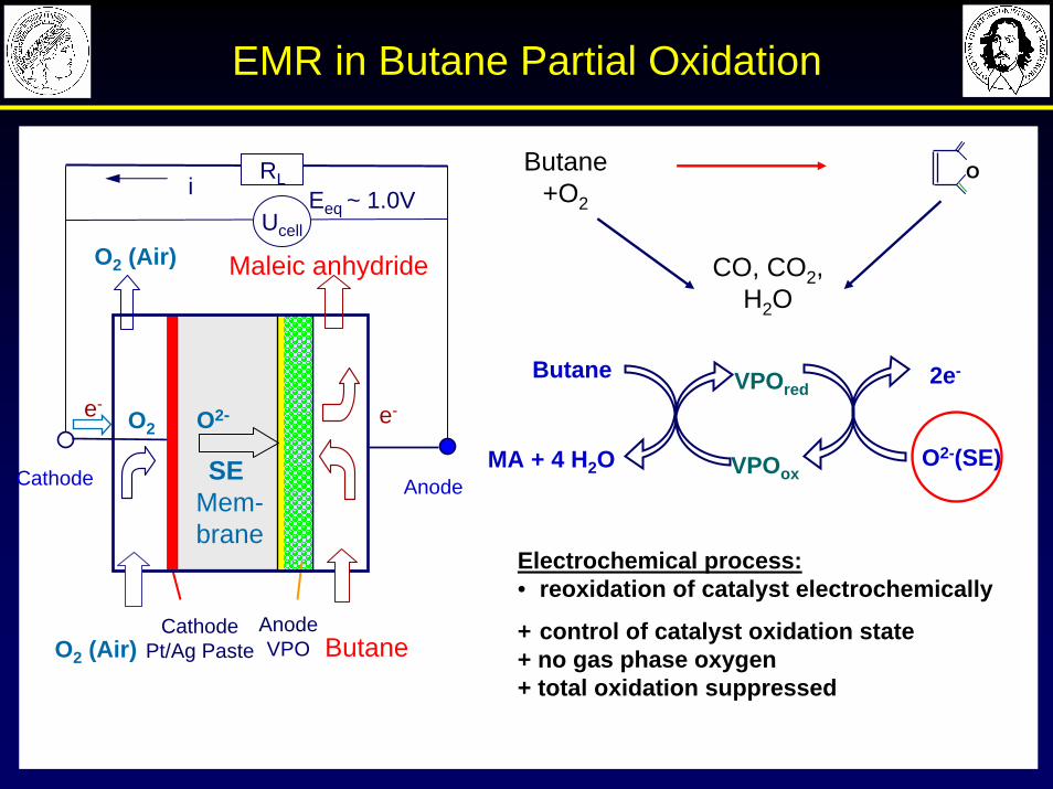
EMR in Butane Partial Oxidation
Electrochemical process:• reoxidation of catalyst electrochemically
+ control of catalyst oxidation state+ no gas phase oxygen + total oxidation suppressed
Cathode
Ucell
iRL
Eeq ~ 1.0V
Anode
AnodeVPO
e-
Butane
e-O2
O2 (Air)
O2 (Air) Maleic anhydride
CathodePt/Ag Paste
SE Mem-brane
O2-
2e-
VPOoxMA + 4 H2O
Butane VPOred
O2-(SE)
O
O
O
MAButane+O2
CO, CO2, H2O
Page 43
EMR Electrode Construction
Advantages:• no prior air separation units• faradaic coupling of oxygen
feed to cell current→ forced periodic operation
• driving force ΔRG ~ U0cell
(fuel cell mode)→ cogeneration of electricity
Present study:Bilayer anode
Optimal case: Anode mixed (O2- and e-) conducting
Composite anode
Page 44
Current Effect in EMR
High current is favorable for butane conversion and MA yield SMA has a maximum w.r.t. current
POxygen/PButane
0.18 0.35 0.53 0.70 0.88 1.06 1.23
Experimental condition:
T=480 ˚C; PButane=0.55 kPa; F=35 ml/min; I=0.44-3.1 mA/cm2
Current, mA Current, mA
Con
vers
ion,
%
Sel
ectiv
ityan
d yi
eld
of M
A, %
S-MA
Y-MA
Butane
Oxygen
S-CO2
S-CO
Butane
O2- O2- O2- O2-
EMR
Ye, Rihko-Struckmann, Munder, Sundmacher. Appl. Catal. A: General, 2005, 285(1-2):86-95
Page 45
Integrated Catalytic Processes –Lecture Outline
Modern Methods in Heterogeneous Catalysis ResearchFritz Haber Institute, Berlin, 24 November 2006
Reactive Distillation
Periodic Separating Reactors
Process Intensification
Membrane ReactorsFuel Cells
Page 46
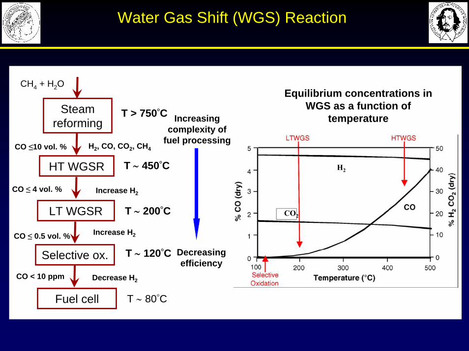
H2, CO, CO2, CH4CO ≤10 vol. %
CO ≤ 4 vol. %
CO ≤ 0.5 vol. %
CO < 10 ppm
CH4 + H2O
Increase H2
Steam reforming
HT WGSR
LT WGSR
Selective ox.
Fuel cell
Increase H2
Decrease H2
T > 750°C
T ∼ 450°C
T ∼ 80°C
T ∼ 120°C
T ∼ 200°C CO2
H2
Increasingcomplexity of
fuel processing
Decreasingefficiency
Equilibrium concentrations in WGS as a function of
temperature
Water Gas Shift (WGS) Reaction
Page 47
Hydrogen Purification- single step processes
WGS with H2-separating
membrane
WGS with periodic separating reactor
CO, H2
CO2,
H2O
H2OH2
Reduction phase
Oxidation phaseSweep
gas
CO + H2O = CO2 + H2
H2
Sweep gas + H2
CO, H2O CO2,
H2O,H2
High pressure
Low pressure
CO, H2O
H2O,H2
CO + H2O = CO2 + H2
CO2 sorbent
CO2 sorbent
WGS with CO2capture
CO + H2O = CO2 + H2
Rune Bredesen, et al., Chemical Engineering and Processing 43 (2004) 1129
Page 48
Phase 1:
Cyclic Ironoxide-Redox WGS
PrOx PEM
Steam Reforming
PrOx PEM
Reduction of Iron oxideGas (CO, H2) + Fe3O4 → FeOX + CO2 + H2O
CO2, H2OΔH < 0
ΔH > 0
Overall reactionCO+H2O→CO2+H2
ΔH = – 41kJ/mol
Cyclic Ironoxide-Redox WGS
Phase 2:
H2O
Re-Oxidation with SteamH2O+ FeOX → Fe3O4 + H2
H2
CO H2
Periodic Separating Reactor
Page 49
Feasibility of Cyclic WGS
0.00 0.25 0.50 0.75 1.000
500
1000
1500
2000
2500
CO
2 fo
rmat
ion
rate
, rC
O2 /
[μm
ol /
min
/ g c
at]
Reduction time, t / [min]
Cr2O3-Fe3O4-CeZrO2
mcat = 0.06 g
T = 740 0CF = 120 ml/min
a
CO turn off
yFCO = 40 vol. %
Reduction with CO
CO CO2
0.00 0.25 0.50 0.75 1.000
1000
2000
3000
4000
5000
6000
7000
8000
9000
Cr2O
3-Fe
3O
4-CeZrO
2
mcat = 0.06 g
T = 740 0CF = 120 ml/minyF
H2O= 75 vol. %
H2
prod
uctio
n ra
te, r
H2 /
[μm
ol/ m
in /
g cat]
Reoxidation time, t / [min]
H2 reduced sample, XO2= 35 %
CO reduced sample, XO2= 22 %
H2H2O
Re-Oxidation with H2O
Galvita, V., Sundmacher, K., Appl. Catal. 289 (2005) 121
Page 50
Integrated Catalytic Processes –Lecture Outline
Modern Methods in Heterogeneous Catalysis ResearchFritz Haber Institute, Berlin, 24 November 2006
Reactive Distillation
Periodic Separating Reactors
Process Intensification
Membrane ReactorsFuel Cells
Page 51
HT Fuel Cells
HotModule in Magdeburg University
• Developed by MTU CFC Solutions GmbH
• Start in October 2002• Molten-Carbonate Fuel Cell (MCFC)• Feed natural gas
HotModule bei der IPF in Magdeburg
Page 52
Optimized Internal Reforming in MCFC
T = 600 °C
Anode
CO32-
Cathode½O2+CO2+2e-↔CO3
2-
(CH4)(H2)(CO)CO2H2O
O2CO2
Exit
Electrolyte
e-
CH4H2O
Ucell
H2 + CO32- ↔H2O + CO2+2e-
CO + CO32- ↔ 2CO2+2e-
CH4 + H2O ↔ CO + 3H2CO + H2O ↔ CO2 + H2
(N2)(H2O)
Internal ReformingO2N2
(Luft)
Catalytic Combustion
• Mass coupling (reforming + WGS + electrochemical Oxidation• Energetical coupling (ΔHr)
Page 53
Optimization of operating conditions
( ) max!,,/,, →Γ backairinael RCS λη
„base case“
Icell=0.7
146.5 mA/cm²
Page 54
Optimization of reforming catalyst distribution
( ) max!,,,/,, →Γ Dabackairinael FRCS λη
„base case“
Icell=0.7
P. Heidebrecht, Fortschritt-Berichte, VDI-Verlag, Düsseldorf, 2005.P. Heidebrecht, K. Sundmacher, Ind. Eng. Chem. Res.44 (10), 2005
146.5 mA/cm²
Page 55
Integrated Catalytic Processes –Lecture Outline
Modern Methods in Heterogeneous Catalysis ResearchFritz Haber Institute, Berlin, 24 November 2006
Reactive Distillation
Periodic Separating Reactors
Process Intensification
Membrane ReactorsFuel Cells
Page 56
Many thanks for scientific co-operation with
Prof. A.Seidel-Morgenstern, A. Tota (MR)
Prof. K. Sundmacher Dr. Zhiwen Qi (RD)M. Chalakova (RD)Dr. V. Galvita (C - WGS)Dr. Ye, B. Munder, L. Chalakov (EMR)Dr. P. Heidebrecht (MCFC)
Acknowledgements
Modern Methods in Heterogeneous Catalysis ResearchFritz Haber Institute, Berlin, 24 November 2006