Integrated Design and Manufacturing of Thermoelectric Generator using Thermal Spray
Lei Zuo, Jon Longtin, Sanjay Sampath
State University of New York at Stony Brook
Qiang Li Brookhaven National Laboratory
2012 DOE Thermoelectrics Workshop March 20-22th, Baltimore, MD
Presentation Outline
• Overall Concept
• Recent Progress – Thermal spray of Mg2Si
– Melt spinning of MnSi1.75 (High Manganese Silicide)
– 3D device fabrication
• Summary and Future Work
Integrated Design and Manufacturing
Exhaust pipe with heat sink fins
Bottom electrical insulation layer Bottom electrical conductor strips
TE layer inducing diffusion barrier Top electrical conductor strips
Top electrical insulation layer Coolant liquid
Cooling jacket
• Abundant low-cost feedstock
• Directly fabricate onto exhaust pipes
• Non-equilibrium synthesis for improved ZT
• Industrial process- based: thermal spray and laser micromachining
• Reliable interface and durability without soldering or clamping
Material Selection: Metal Silicides (Mg2Si and MnSi1.75)
• Metal Silicides: slightly lower ZT, but abundant, inexpensive, no toxicity issues.
W. Luo, H. Li, Y. Yan, Z. Lin, X. Tang, Q. Zhang, and C. Uher, Intermetallics, 2011
J-Y Jung and I-H Kim, Electronic Materials Letters, 2010
Non-Equilibrium Synthesis: Melt Spinning and Thermal Spray
Hot press
Melt spinning
Melting, rapid quenching and consolidation in a single process
High Pressure
Rapid quench
Non-equilibrium Synthesis: Reduced processing time from days to minutes
Types of Thermal Spray
High Velocity Oxygen Fuel (HVOF)
Vacuum Plasma Spray (VPS) Atmosphere Plasma Spray (APS)
http://www.gordonengland.co.uk/hvof.htm
http://www.siemens.com/press/en/presspicture/?press=/en/presspicture /pictures-photonews/2008/pn200807/pn200807-01.htm
Mg2Si by APS (First Trial)
To test the thermal spray process, we used Mg2Si with 98% purity;
* Lower temperature and higher speed are better.
* After thermal spray: MgO and Si phases appear:
Mg2Si + O2 MgO + Si 450 oC
Plasma Gas
Carrier Gas Ar
Undoped Mg2Si by APS (cont)
APS samples show: • Reduced thermal conductivity • Comparable electrical conductivity • But:
- Low Seebeck coefficient - High oxidation (10-16%)
Ref values for bulk: 50 S/m at 50 oC [1] 460 S/m at 20 oC [2]
Ref values for bulk: 500 µV/K at 50 oC [1]
6 (ref)
[1] J-Y Jung and I-H Kim, Electronic Materials Letters, 2010. (using solid state reaction/hot press method) [2] J. Tani and H. Kido, Thermoeletric properties of Bi-doped Mg2Si semiconductors, Physica B, 2005. (SPS method)
Key: Reducing Oxidation with Process Conditions
• Reducing oxidation through: – Spray type: APS, HVOF, VPS
– Processing conditions (temperature, particle velocity, etc.)
– Using a shroud (inert gas injected around thermal spray plume to minimize oxidation)
– Spraying in an inert-gas environment (VPS)
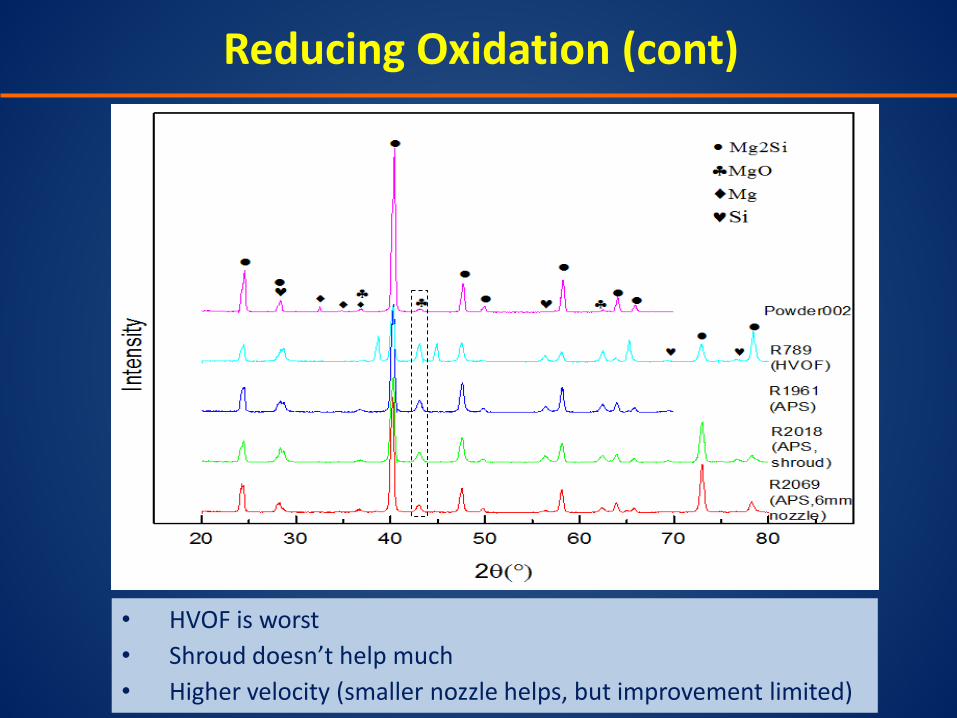
Reducing Oxidation (cont)
• HVOF is worst • Shroud doesn’t help much • Higher velocity (smaller nozzle helps, but improvement limited)
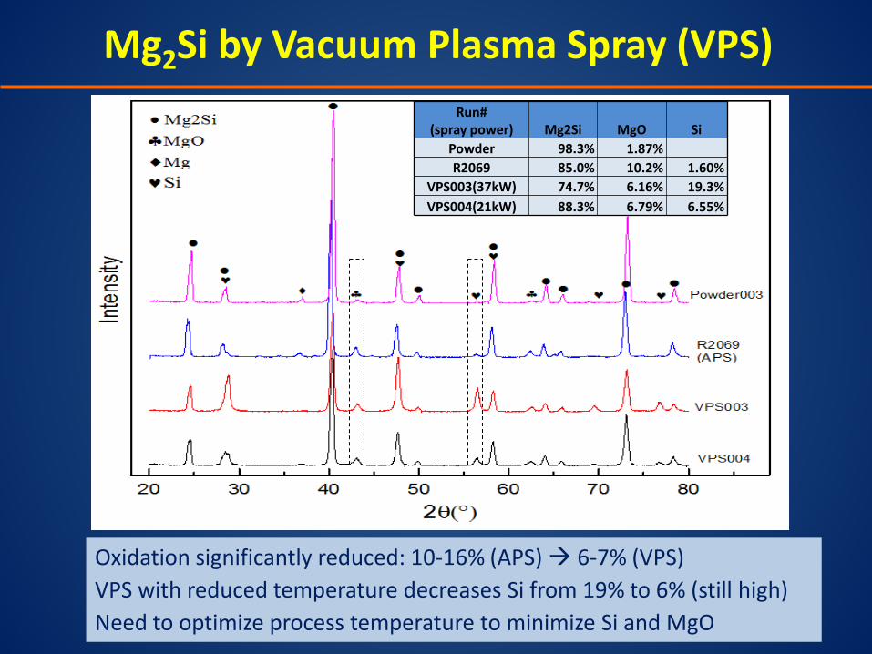
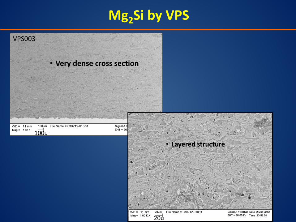
Mg2Si by Vacuum Plasma Spray (VPS)
Oxidation significantly reduced: 10-16% (APS) 6-7% (VPS) VPS with reduced temperature decreases Si from 19% to 6% (still high) Need to optimize process temperature to minimize Si and MgO
Run# (spray power) Mg2Si MgO Si
Powder 98.3% 1.87% R2069 85.0% 10.2% 1.60%
VPS003(37kW) 74.7% 6.16% 19.3% VPS004(21kW) 88.3% 6.79% 6.55%
Mg2Si by VPS
VPS is a promising deposition technique
Th
erm
al c
on
du
cti
vity
W/m
*K
[1] J-Y Jung and I-H Kim, Electronic Materials Letters, 2010. (with solid state reaction/hot press method) [2] J. Tani and H. Kido, Thermoeletric properties of Bi-doped Mg2Si semiconductors, Physica B, 2005. (SPS method)
300 310 320 330 340 3500
-50
-100
-150
-200
-250
-300
VPS003 R1961 R1962
See
beck
Coe
f. (µ
V/K
)
Temperature (K)
Seebeck characterization of newest VPS sample (VPS004) is underway
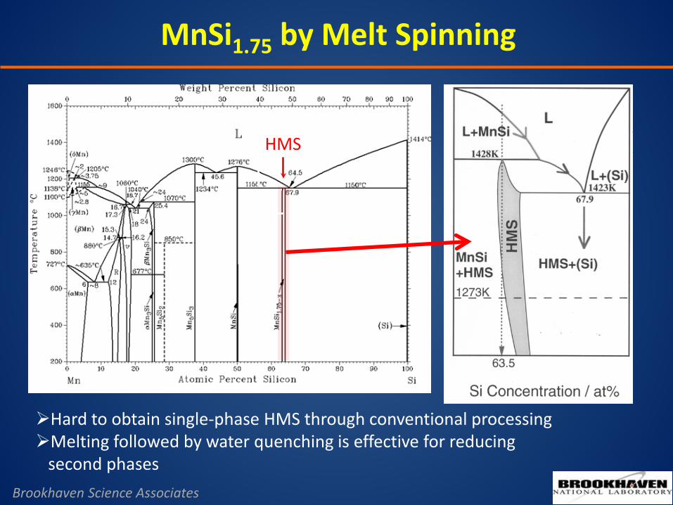
HMS
Hard to obtain single-phase HMS through conventional processing Melting followed by water quenching is effective for reducing second phases
MnSi1.75 by Melt Spinning
Brookhaven Science Associates
Melt-spinning
Mn + Si Powder mixing
(10 min)
Melt-spinning (10 min)
Solid state reaction
Mn + Si Sealed and anneal @1373 K for 2 days
Ground and cold pressed Sealed and anneal @1373 K for 2 days
Melt and quench
Mn + Si Sealed and melted @1473 K for 12 hrs Then water quench
Annealed @ 1273 K for 5 days
SPS @1123K for 10 min with 50 Mpa pressure
(MS) (SSR) (MQ)
MnSi1.75 by Melt Spinning
Brookhaven Science Associates
MnSi1.75 by Melt Spinning
Single-phase HMS can be obtained in < 30 mins Solid state reaction not suitable for HMS
Brookhaven Science Associates
MnSi1.75 by Melt Spinning
sample
Electr. Resist. ρ
(10-5 Ohm-m)
Seebeck (µVK-1)
Power factor (µWcm-1K-2)
Carrier Density pH (1021 cm-3)
Electron Mobility µH (cm2V-1S-1)
Effective mass
m*/me
MS 1.95 119 7.2 1.24 2.5 7.4
MQ 2.14 112 5.8 0.88 3.1 5.5
SSR 2.30 110 5.2 1.04 2.6 6.0
Room temperature thermoelectrical performances
Brookhaven Science Associates
Goal: Transition Melt Spinning to Thermal Spray
Hot press
Melt spinning
Thermal Spray
High Pressure
Rapid quench
3D Device Fabrication with Thermal Spray
(Grid spacing: ¼”)
Conductor layer – good mechanical bonding; dense coating
Thick deposits (3-4 mm) of FeSi for TE layer
Exhaust pipe with heat sink fins
Bottom electrical insulation layer Bottom electrical conductor strips
TE layer inducing diffusion barrier Top electrical conductor strips
Top electrical insulation layer Coolant liquid
Cooling jacket
p leg
p leg
n leg
n
leg
n leg
Step 1: bottom electrode
/insulating layer
Step 2: n and p legs
Step 3: Top electrode
Step 1: Bottom Conductor & Laser Patterning
Design: 0.5mm thick Alumina + 0.5mm Copper on 2” x 2” Aluminum Substrate
Side View
Insulating alumina layer
0.050” Gap
Cu layer
Laser Micromachining: - Nd:YLF laser: 20W, 532 nm, 150 ns, 1 kHz rep rate
Step 3: Forming Top Electrode - Bridging
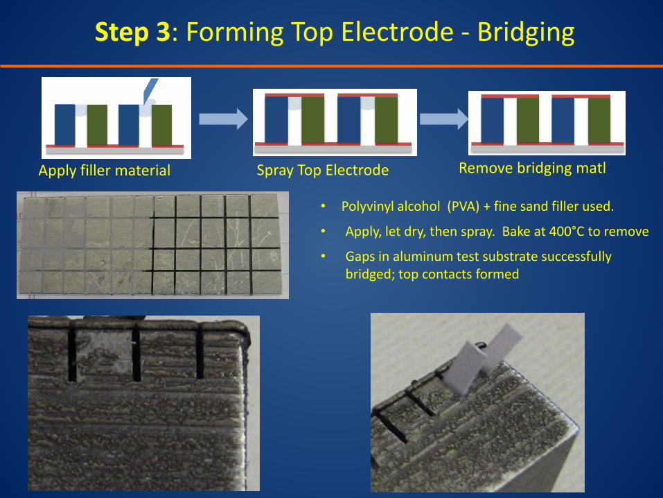
Apply filler material Spray Top Electrode Remove bridging matl
• Polyvinyl alcohol (PVA) + fine sand filler used.
• Apply, let dry, then spray. Bake at 400°C to remove
• Gaps in aluminum test substrate successfully bridged; top contacts formed
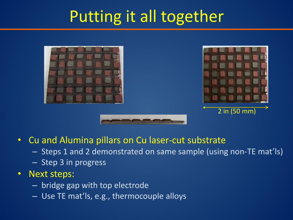
Putting it all together
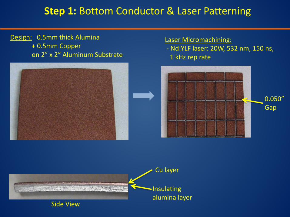
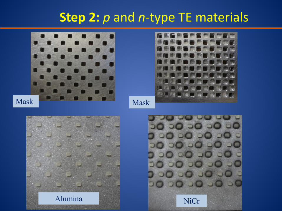
• Cu and Alumina pillars on Cu laser-cut substrate – Steps 1 and 2 demonstrated on same sample (using non-TE mat’ls) – Step 3 in progress
• Next steps: – bridge gap with top electrode – Use TE mat’ls, e.g., thermocouple alloys
2 in (50 mm)
Summary
• Thermal spray TE mat’ls: reduced thermal conductivity, reasonable electrical conductivity, but oxidation is an issue – APS shows high oxidation; degrades electrical properties – HVOF shows even more oxidation – VPS reduces oxidation; process temperature now being optimized
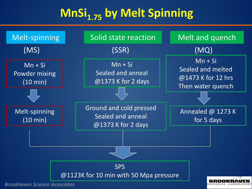
• Melt spinning achieves good result on MnSi1.75
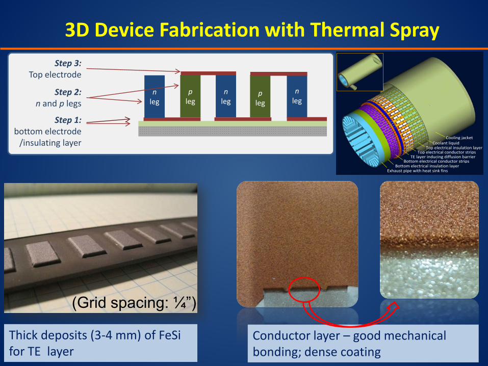
• Thermal Spray 3D TE structures – Good mechanical bonding of bottom conducting layer as sprayed – Thick checkerboard pattern sprayed for eventual TE materials – Bridging by thermal spray for top electrode fabrication demonstrated
Future Work • Further property improvement using VPS
• Exploration of high-magnesium silicide (HMS) – transfer the success of melt spinning to thermal spray
• Fabricate functional TE prototype using thermal spray
• The authors gratefully acknowledge funding for this work from: – NSF and DoE through the NSF/DoE Thermoelectrics
Partnership: Integrated Design and Manufacturing of Cost-Effective and Industrial-Scalable TEG for Vehicle Applications (CBET-1048744)
– New York State Energy Research and Development Authority (NYSERDA)
– Stony Brook University –Brookhaven National Laboratories 2010 Seed Grant Program
Acknowledgements