Carrier Ethernet-based E-band wireless backhaul is highly cost- effective in supporting large-scale deployment of small cells. It has clear advantages in cost, throughput, and network capacity.
White Paper: Kintex-7, Kintex UltraScale, and Zynq-7000 Devices
WP457 (v1.0) February 24, 2015
Integrated Single System-on-a-Chip Mobile Backhaul for
Small-Cell DeploymentsBy: Carl Cao and Michel Pecot
ABSTRACTThis white paper analyzes the requirements for mobile wireless backhaul. In particular, it focuses on the backhaul technology required for deploying 3G/4G small cells, which have their own specif ic characteristics and requirements.The technology has matured to the point where E-band radios, in conjunction with Carrier Ethernet networking, can support the backhaul needs accompanying deployment of numerous small cells. This backhaul model results in clear advantages in functionality, throughput, carrier-grade OAM, and high reliability.Xilinx® All Programmable FPGAs and SoCs are designed to address variations in form factors, deployment scenarios, and cost requirements. Designers have the capability to choose from the same highly flexible family of devices, mixing and matching different blocks from the same rich set of IP cores for the optimal balance of application requirements and cost.
Integrated Single System-on-a-Chip Mobile Backhaul for Small-Cell Deployments
IntroductionLarge-scale deployment of 4G LTE networks is proceeding globally. To support the resulting increased capacity, the backhaul network also needs to be upgraded. This provides new business opportunities to wireless semiconductor players. Xilinx, through its All Programmable FPGA and SoC solutions, is an industry leader in supplying IC devices to the wireless infrastructure market, and is targeting wireless backhaul for strong growth. Xilinx products provide unmatched advantages in flexibility, programmability, and product evolution.
This white paper provides an analysis of the development and evolution of wireless backhaul networks. It identif ies the key network functions required to support continued mobile traff ic growth, and presents the IC products and Intellectual Property (IP) cores from Xilinx that enable wireless infrastructure vendors to design and implement these functions eff iciently.
Mobile Backhaul NetworkMobile users are continually upgrading to smart phones with ever more data-hungry applications. The wireless networking industry has forecast that, by 2017, each month’s global mobile data traff ic could increase by 11-fold, surpassing 10 exabytes in just a few years.[Ref 1] This places increasing demand on the wireless backhaul networks that are responsible for delivering user data within the mobile wireless network.
The mobile wireless network(1) can be divided into several segments, as shown in Figure 1. The backhaul network connects the Base Transceiver Stations (BTS)(2) to and from the rest of the network. As the amount and speed of data delivered over the air to end-users increases, the capacity of the backhaul network needs to scale up.
Figure 2 shows that the mobile backhaul network is multi-layered, multi-technology—wired, f iber, and wireless—and highly scalable. It needs to connect high-capacity macro base stations and low-capacity small cells alike, reliably and cheaply, across large geographical areas. It is therefore important that a variety of backhaul options are available to maximize the network’s capacity and reach while minimizing its cost.
X-Ref Target - Figure 1
Figure 1: Simplified View of the Mobile Wireless Network
1. This white paper focuses on the mobile backhaul network, in particular wireless backhaul; hence, it does not include the access link between the BTS and the user terminal.
2. A BTS is also called an enhanced NodeB (eNodeB) in an LTE or LTE-A network.
Integrated Single System-on-a-Chip Mobile Backhaul for Small-Cell Deployments
The backhaul network can be segmented into the aggregation network and last mile connections. Aggregation nodes essentially collect traff ic from base stations and other aggregation nodes. Connectivity might be supplied by wired or wireless links, depending on the cost to reach a particular site.
Of particular interest to increase capacity are the so-called micro-, pico-, and femto-cells. These cell sites are designed to f ill in coverage and capacity holes in the overall network. They have become a key technology option by which wireless operators plan to address capacity issues.[Ref 2]
Small-cell implementations have specif ic backhaul requirements. Massive deployment of small cells is extremely cost-sensitive and must stay within strict budgetary limits to be market-competitive. They must be simple, and preferably comprise a single field-replaceable unit, including fully integrated backhaul. The total power requirement must be as low as possible, ideally reduced to what can be supplied by Power-over-Ethernet (PoE), a maximum of 25.5 watts.[Ref 3] As small cells are deployed in congested and obstruction-littered locations, the backhaul edge-node must also be flexible enough to work in different, sometimes unpredictable RF environments.
As can be seen in Figure 2, the backhaul network comprises a large percentage of the overall mobile network equipment. Small cells, when they are deployed at a large scale, will further increase the need for backhaul equipment. As capacity demand increases, more and higher-capacity links need to be installed. The performance of the backhaul network directly
Integrated Single System-on-a-Chip Mobile Backhaul for Small-Cell Deployments
impacts the end-user experience, as measured by the Quality of Service (QoS)—latency, packet delay variations, and other impediments that affect the data rates delivered over the backhaul.
Evolution of Mobile Backhaul NetworksMobile backhaul networks are converging onto the All IP infrastructure, particularly with carrier Ethernet as the network link layer. Carrier Ethernet is leveraged to lower the backhaul cost compared to traditional leased lines, and to exploit the economies of scale in cost and industry technical advances. Ethernet supports vastly increased capacity and follows a Moore's law-like capacity-to-cost curve. It has become a favored choice because of its simplicity, multi-service support, statistical traffic aggregation, and fast technology advancements. Ethernet, by now, has overcome its earlier shortcomings in QoS, synchronization, carrier grade availability, and network management.
Backhaul QoS can be supported by implementing traff ic management and prioritization to differentiate packet flows for latency, delay variability, and other traff ic parameters. The standard carrier-grade management solutions like IEEE Std 802.1ag[Ref 4] and ITU Y.1731[Ref 5] have become more robust and now match those available for SDH/SONET transport. Fault-tolerant and high-availability techniques (e.g., ITU G.8032 ERPS[Ref 6]) have been transferred to carrier Ethernet from SONET/SDH. Timing and synchronization of large-scale networks have also been developed— as, for example, the IEEE Std 1588v2 Precision Timing Protocol (PTP)[Ref 7], whose gradual deployment is key to the move away from leased lines.
Wired Ethernet can be expected to be a major part of the backhaul, either over fiber or T1/E1 leased lines. However, wireless connections are especially attractive since they are often lower cost. In some countries today, more than 60% of the mobile network backhaul is already provided by wireless.
Microwave (in particular the 20–30 GHz band of spectrum, as shown in Figure 3) is a proven technology, and provides effective data rates per link up to a few gigabits per second.
However, with projected mobile data traff ic growth, microwave alone could become a bottleneck to capacity. Millimeter waves (30–100 GHz) have now become attractive in connecting small-cell base
X-Ref Target - Figure 3
Figure 3: Frequency Bands Applicable to Wireless BackhaulWP457_03_111814
Integrated Single System-on-a-Chip Mobile Backhaul for Small-Cell Deployments
stations. Although the radio range is much shorter at such frequencies, the available bandwidth is much more abundant. Of special interest in this white paper is the so-called E-band, whose two 5 GHz segments are located at 71–76 GHz and 81–86 GHz.(1) These bands are “lightly” licensed in the United States under FCC Part 101 [Ref 8], and have become available in most other countries as well. E-band can be used for terrestrial line-of-sight (LoS), short-range, high-bandwidth links and offers reliable communications at distances up to 2 km in all weather conditions. The available bandwidth allows reaching data rates close to what would be achieved over a f iber.
Microwave BackhaulThe 8–30 GHz microwave spectrum has properties that allow good receive sensitivity; however, it is susceptible to precipitation and atmospheric absorption, and is best implemented with Line-of-Sight (LoS) point-to-point paths between antennas.
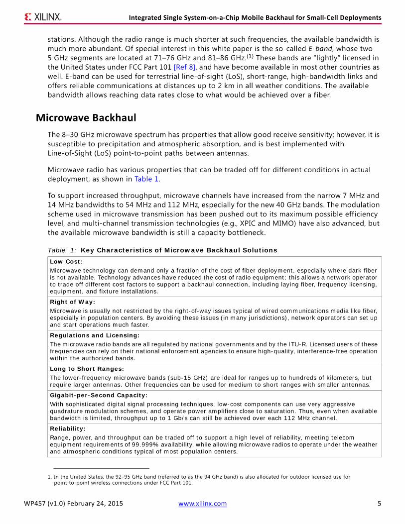
Microwave radio has various properties that can be traded off for different conditions in actual deployment, as shown in Table 1.
To support increased throughput, microwave channels have increased from the narrow 7 MHz and 14 MHz bandwidths to 54 MHz and 112 MHz, especially for the new 40 GHz bands. The modulation scheme used in microwave transmission has been pushed out to its maximum possible eff iciency level, and multi-channel transmission technologies (e.g., XPIC and MIMO) have also advanced, but the available microwave bandwidth is still a capacity bottleneck.
1. In the United States, the 92–95 GHz band (referred to as the 94 GHz band) is also allocated for outdoor licensed use for point-to-point wireless connections under FCC Part 101.
Table 1: Key Characteristics of Microwave Backhaul SolutionsLow Cost:Microwave technology can demand only a fraction of the cost of fiber deployment, especially where dark fiber is not available. Technology advances have reduced the cost of radio equipment; this allows a network operator to trade off different cost factors to support a backhaul connection, including laying fiber, frequency licensing, equipment, and fixture installations.
Right of Way:Microwave is usually not restricted by the right-of-way issues typical of wired communications media like fiber, especially in population centers. By avoiding these issues (in many jurisdictions), network operators can set up and start operations much faster.
Regulations and Licensing:The microwave radio bands are all regulated by national governments and by the ITU-R. Licensed users of these frequencies can rely on their national enforcement agencies to ensure high-quality, interference-free operation within the authorized bands.
Long to Short Ranges:The lower-frequency microwave bands (sub-15 GHz) are ideal for ranges up to hundreds of kilometers, but require larger antennas. Other frequencies can be used for medium to short ranges with smaller antennas.
Gigabit-per-Second Capacity:With sophisticated digital signal processing techniques, low-cost components can use very aggressive quadrature modulation schemes, and operate power amplifiers close to saturation. Thus, even when available bandwidth is limited, throughput up to 1 Gb/s can still be achieved over each 112 MHz channel.
Reliability:Range, power, and throughput can be traded off to support a high level of reliability, meeting telecom equipment requirements of 99.999% availability, while allowing microwave radios to operate under the weather and atmospheric conditions typical of most population centers.
Integrated Single System-on-a-Chip Mobile Backhaul for Small-Cell Deployments
E-band RadioWorking at E-band frequencies has several advantages. Because there is more spectrum available, much larger channels—e.g., 250–5000 MHz—can be used. The E-band signal is highly directional, and small form-factor antennas can be used at the same gain (see Figure 4). For example, a 30 cm diameter parabolic antenna has 45 dBi gain at 71 GHz compared to 32.5 dBi at 18 GHz.
Looking at it in another way, using same-size antennas, the beamwidth of a 71–76 GHz link is just one-quarter the width of that of an 18 GHz link; this means that within the same geographical area, it potentially accommodates an increased number of links. E-band links cause much less interference to each other using the same frequencies in close proximity; they also potentially reduce equipment cost, as there is less need for additional signal processing to combat such interference. All this enables very high channel re-use, thus easing the task of frequency planning and improving network architecture flexibility.
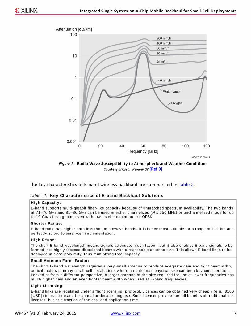
E-band frequencies are sensitive to atmospheric attenuation, as shown in Figure 5. To retain the same level of 99.999% reliability, this implies a useful range of 1–2 km for most parts of the world under the most common weather conditions. However, the reduced range is in fact a benefit for small cell backhaul; faster signal attenuation means better signal isolation and therefore a denser, more efficient link layout. Small cells, additionally, can gain from using smaller, unobtrusive backhaul antennas—for example, in installations on street-light poles.
X-Ref Target - Figure 4
Figure 4: Comparison of E-band Radio Wave Beam and Microwave BeamWP457_04_090914
Integrated Single System-on-a-Chip Mobile Backhaul for Small-Cell Deployments
The key characteristics of E-band wireless backhaul are summarized in Table 2.
X-Ref Target - Figure 5
Figure 5: Radio Wave Susceptibility to Atmospheric and Weather Conditions Courtesy Ericsson Review 02 [Ref 9]
Table 2: Key Characteristics of E-band Backhaul SolutionsHigh Capacity:E-band supports multi-gigabit fiber-like capacity because of unmatched spectrum availability. The two bands at 71–76 GHz and 81–86 GHz can be used in either channelized (N x 250 MHz) or unchannelized mode for up to 10 Gb/s throughput, even with low-level modulation like QPSK.
Shorter Range:E-band radio has higher path loss than microwave bands. It is hence most suitable for a range of 1–2 km and perfectly suited to small-cell implementation.
High Reuse:The short E-band wavelength means signals attenuate much faster—but it also enables E-band signals to be formed into highly focused directional beams with a reasonable antenna size. This allows E-band links to be deployed in close proximity, thus multiplying total capacity.
Small Antenna Form-Factor:The short E-band wavelength requires a very small antenna to produce adequate gain and tight beamwidth, critical factors in many small-cell installations where an antenna’s physical size can be a key consideration. Looked at from a different perspective, a larger antenna of the size required for use at lower frequencies has much higher gain and an even tighter beamwidth when used at E-band frequencies.
Light Licensing:E-band links are regulated under a “light licensing” protocol. Licenses can be obtained very cheaply (e.g., $100 [USD]) in real time and for annual or decade-long use. Such licenses provide the full benefits of traditional link licenses, but at a fraction of the cost and application time.
Integrated Single System-on-a-Chip Mobile Backhaul for Small-Cell Deployments
Regulatory Advantage of E-band Radio
In the United States, E-band spectrum is used by means of a “light licensing” regulation, which requires lower cost and little delay. The cost can be as low as a hundred dollars per link for a decade of use.
The entire 5 GHz bandwidth can be used unchannelized, which makes it possible to achieve very high throughput at comparatively low link equipment costs. FCC regulations allow E-band more generous emission levels [Ref 8] with up to 3 watts of output power. This is summarized in Table 3.
In Europe, the licensing process for most countries is similar to the US, with the difference that the spectrum is channelized into nineteen 250 MHz channels. This, however, makes only a small difference, as channels can be bundled together to achieve higher capacity.
E-band Deployment Challenges
Despite many advantages, the widespread deployment of E-band radios faces several important challenges. These include:
• Cost-effective hardware (e.g., power amplif ier [PA] linearity combined with sufficient gain)
• Receiver phase noise tolerance
• RF component costs needed to support high bandwidths
The cost of high-performance E-band radio components can potentially limit E-band system architectures and performance:
Link Reliability:The atmospheric attenuation characteristics of E-band radio wavelengths are similar to those of the much lower frequency 23–38 GHz bands. This robust weather resilience allows the link planner to utilize E-band to support reliable links in a similar manner as microwave implementations.
Higher Output Power:United States FCC regulations allow E-band output power of up to 3 watts, other millimeter bands are limited to a few hundred milliwatts to 1 watt. Lenient antenna gain regulation means that the E-band antenna EIRP can be leveraged to support high throughput and a more reliable link.
Table 3: Key Regulated Radio Requirements of E-band, US and Europe (Typical)
System Parameter US (FCC) Requirement Europe Requirements (Typical)
Maximum Tx Power 3W (35 dBm) 1W (30 dBm)
Maximum EIRP 300 kW (55 dBw) 300 kilowatts (55 dBw)
Integrated Single System-on-a-Chip Mobile Backhaul for Small-Cell Deployments
• With an increase in bandwidth (for example, from 250 MHz to 1 GHz), PA cost increases signif icantly. This increase is compounded by the need to operate closer to saturation to optimize efficiency.
• For the receiver, accuracy of the local oscillator (LO) is a key limiting factor. In order to contain cost, robust resistance to phase noise in the LO and analog components is essential in the receiver modem, which requires advanced signal processing in channel phase recovery.
Supporting multi-gigahertz-wide bandwidths is a significant challenge for both digital signal processing resources and RF components. As an alternative, using multiple processing chains with multiple channels (at reduced bandwidth) also increases the cost of equipment as more of them are needed.
Capacity-Enhancing Techniques for the Wireless Mobile BackhaulIn order to increase the throughput of mobile backhaul links, a number of spectral efficiency techniques have been developed; they can be applied to either microwave or E-band radio:
• Modulation has been progressively pushed higher in order to support higher data rates. With the current state of the art in microwave backhaul, the modulation order can be as high as 2048QAM, or theoretically 1.2 Gb/s throughput for a 112 MHz channel. In the case of E-band, 880 Mb/s can be supported with 16QAM over 250 MHz.
• It is not possible to operate under higher modulation orders in all link conditions. Thus, adaptive modulation and coding (AMC) techniques have been developed to automatically adjust the modulation order and coding rate to match RF conditions.
• Cross-polarization interference cancellation (XPIC) and MIMO techniques allow the same frequency to be multiplexed over multiple channels to achieve up to four times the data rate. See Figure 6.
Not all capacity-enhancing techniques are practical for microwave and E-band radio in all instances or applications. However, the technological envelope is being pushed constantly, and these new technologies could become more realistic—technically as well as economically—later on.
X-Ref Target - Figure 6
Figure 6: 4x4 LoS MIMO with Spatial and Polarity MultiplexingWP457_07_111814
Integrated Single System-on-a-Chip Mobile Backhaul for Small-Cell Deployments
Carrier Ethernet Backhaul Networks Carrier Ethernet is the most common Layer 2 transport in the aggregation network and the last-mile connections to cell sites, regardless of the physical layer (e.g., optical f iber, T1/E1, or wireless). This Layer 2 technology is closely coupled with IP, and expanding from the enterprise and local-area networks to wide-area and carrier networks is simple and less costly compared to alternative methods. It integrates highly developed network OAM protocols, security support, reliability features comparable with traditional SDH/SONET, flexible transport architecture, and easy capacity allocation schemes. See Figure 7.
The following points introduce a number of concepts used in the rest of this document:
• An End-Node in the backhaul network is directly or indirectly connected to the base stations.
• An Aggregation Node connects one or more end-nodes, then routes mobile network traffic to or from the metro network (although it could also connect to other aggregation nodes).
• A Transport Node connects one or more aggregation nodes or other transport nodes so that traff ic can be routed to the rest of the network.
• A Relay Node connects an end-node to an aggregation node, which can also act as an end-node if it can support the mobile network function of a specif ic cell site.
X-Ref Target - Figure 7
Figure 7: Ethernet in the Wireless BackhaulWP457_08_090914
Integrated Single System-on-a-Chip Mobile Backhaul for Small-Cell Deployments
In Figure 7, a router or switch at point (F) interconnects the backhaul network, consisting of one or more aggregation nodes and many end-nodes, to the metropolitan (wide-area) network. This so-called aggregation network could connect directly to the metro network or still run one or more levels deep—for example, through point (C) to interconnect the rest of the network.
Ethernet over wireline connections and over wireless connections differs principally in the physical layer. As in Figure 7, part of the aggregation network [ (E), (F), and (G) ] can be fully wireline-based with multiple nodes. Part of it can also be based on a mix of f iber, [ (F) and (K) ] and wireless nodes [ (H), (I), (J), and (L) ]. Exactly what physical link to use is mostly based on availability, cost, and geographical conditions.
Typically, the capacity of an aggregation network is dimensioned to the capacity needs of a specif ic geographical area. In the example shown in Figure 7, this sub-network can have tens of gigabits per second capacity [ (E), (F), and (G) ], and is connected to a metropolitan network of at least comparable or often much higher capacity [ (B), (C), and (D) ].
Backhaul Network TopologiesThere are many ways to organize backhaul network nodes—i.e., end-nodes and aggregation nodes in a network over a geographic area. Figure 8 illustrates the most prevalent topologies.
Integrated Single System-on-a-Chip Mobile Backhaul for Small-Cell Deployments
• Point-to-Point Relay: This is the simplest case of an end-node connecting to the aggregation node through a relay node, which can itself actually act as an end-node. See Figure 8(a).
• Star Topology: Several end-nodes connect to a single aggregation node in a star-like shape. See Figure 8(b).
• Ring Topology: A number of aggregation and transport nodes are connected together to form a ring. Traffic from one node to another can be routed only in one direction in the ring; one or more of the nodes connects to the core network. See Figure 8(c)
• Linear Topology: A number of aggregation and transport nodes are connected together in a linear cascaded path. In such a case, a redundant link is provisioned in standby mode, parallel to the active link, so that traffic can be switched to this segment in case of a link failure. See Figure 8(d).
The capacity of an aggregation node must be dimensioned to support the sum of the throughput of the end-nodes. If an aggregation node also connects to other aggregation nodes, its capacity dimensioning can be expanded even further. This determines whether an aggregation node must be equipped with a number of lower-capacity Ethernet interfaces to the end-nodes, and one or more high-capacity interfaces for the wireless backhaul network.
Wireless Links in the Ethernet Aggregation NodesAggregation nodes have much higher capacity than end-nodes and must be more reliable, as a single-node failure can lead to failure of multiple cell sites. For these reasons, it can be expected that the requirements for the aggregation nodes(1) differ from those of the end-nodes. Some of the key requirements of wireless links in an aggregation node are summarized below:
• High Capacity and High Bandwidth: The aggregation node must be dimensioned for the peak throughput of the connected end-nodes. On a per-link basis, it also leads to substantially more bandwidth, which gives rise to opportunities for higher-frequency bands.
• Transport Architecture: Depending on the network topology, an aggregation node also acts as a router for forwarding traff ic from other aggregation nodes, which further increases the throughput requirements.
• Many Network–Network Interfaces and Radios: As a single aggregation node is collecting traff ic from many cell sites, typically with some degree of geographical dispersion, it must integrate the interfaces and radios to connect to many nodes.
• Reliability and Protection: Given the fact that aggregation nodes support wireless coverage in a signif icant geographical area, they must be reliable 99.999% of the time. Such node level reliability requires automatic protection switching (APS) and link redundancy.
With a particular focus on small cell deployments in this white paper, the obvious requirements are small form-factor and low cost. However, there are also other important considerations for nodes serving numerous small cells. These are given below:
• Geographical Location and Range: Small cells are likely to be located more closely together. Where wireless backhaul is required, it is therefore also of shorter range (i.e., < 1,000m). This opens up more opportunities for higher-frequency spectrum such as E-band (60–95 GHz).
1. Requirements for transport nodes are similar to aggregation nodes with the exception that they do not connect to end-nodes, and hence do not need the additional (lower capacity) Ethernet interfaces.
Integrated Single System-on-a-Chip Mobile Backhaul for Small-Cell Deployments
• Point-to-Multi-Point (PMP) Support: PMP, by multiplexing end-nodes over shared spectrum, is usually preferred where available spectrum is limited. It is even more relevant in small cell applications as it allows more streamlined radios, less power consumption, and reduced form-factor.
• Time-Division Duplexing (TDD) Support: Using TDD at the small cell aggregation nodes further avoids the need for duplexers, which again contributes to reduction in form-factor and power consumption.
• Environmental Constraints: Small cells are more likely to be deployed in complex RF environments, such as in congested geographical areas. As a result, problems with physical obstruction can be expected and, if present, must be worked around.
A key planning issue of a wireless backhaul network is to dimension the capacity of each aggregation node. The Next Generation Mobile Network Alliance (NGNM) had studied the capacity needs of the wireless backhaul in the context of the 4G LTE wireless network deployment.[Ref 10]
As shown in Figure 9, the NGNM study concluded that each aggregation node that connect to up to ten tri-cell LTE eNodeB supporting a 4 x 2 MIMO single 20 MHz LTE carrier requires approximately 1 Gb/s throughput. On top of this, a 25% overhead can typically be assumed to support IPSec ESP encryption, OAM, and X2 interfaces.
Overall, the capacity is dominated by the downlink: For up to f ive single cells, the required aggregation node capacity is initially flat, and then rises linearly with the number of eNodeBs.
Wireless Last-Mile LinksThe wireless last-mile link connects directly to an end-node at a cell site. The end-node can be integrated into the base station, or connected to the base station backhaul Ethernet interfaces. In the case of macro-cells, the end-node can support multiple base stations, possibly using a different radio access technology (RAT) or even different operators' networks. Even in the case of a single base station, multiple cells or multiple carriers might need to be supported.
X-Ref Target - Figure 9
Figure 9: Estimates of Throughput Support for a Cluster of LTE eNodeBs(Courtesy of NGMN Alliance)
Integrated Single System-on-a-Chip Mobile Backhaul for Small-Cell Deployments
The typical characteristics of an end-node are captured below:
• Lower Capacity: The end-nodes usually require less capacity compared to aggregation nodes, typically in hundreds of Mb/s rather than Gb/s.
• Security: Support for backhaul security (based on IPSec) is typically required at the end-node. Additionally, in cases of shared backhaul transport, support for VPN is necessary to segregate traff ic and signaling from different operators.
• Flexible Capacity Allocation: In order to support multiple network operators, the end-node must be able to provide flexible capacity allocation capabilities, such that an operator can be provisioned only for the capacity needed and paid for by that operator.
Capacity dimensioning is quite straightforward, as shown in Figure 9, using a similar methodology.
Key Enablers for Ethernet BackhaulCarrier Ethernet has a large ecosystem enabling the sharing of technology advances in both telecom and networking industries. Today, it has evolved with the required features for supporting wireless backhaul carrier-grade operations, including enhanced QoS, carrier-grade OAM, synchronization and timing, and network protection capabilities, as shown in Table 4.
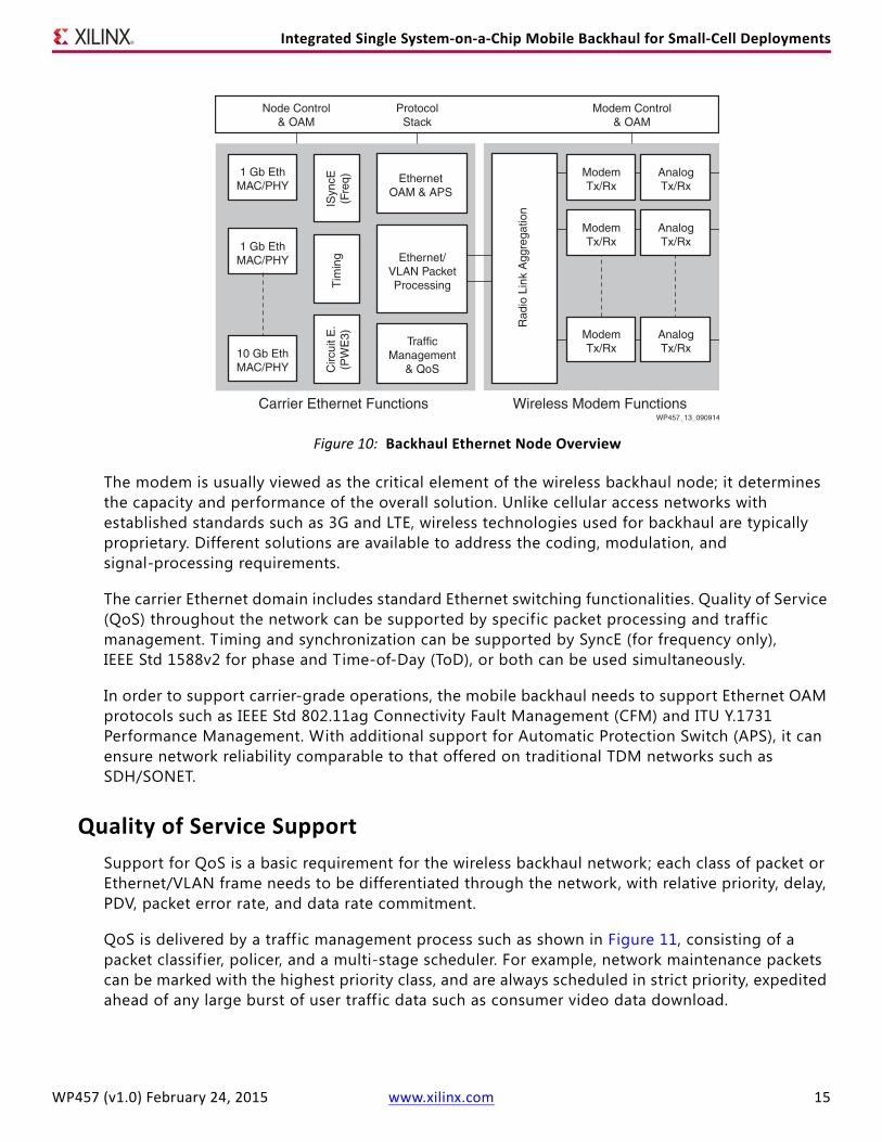
The main functionalities of a carrier Ethernet wireless backhaul node are depicted in Figure 10. These functions can be partitioned into a carrier Ethernet domain and a Wireless domain. The backhaul end-node usually supports multiple wireless modems and associated analog RF transmit and receive chains. The radio link aggregation function collects and distributes the traff ic from/to the different modems.
Table 4: Key Challenges for Ethernet Backhaul
Requirements Carrier Ethernet Features Comments
Quality of Service (QoS)While some QoS can be more relaxed for a packet based mobile backhaul, specific classes of data for wireless networks still require stringent and predictable QoS.
Packet network design (carrier Ethernet in particular) responded to QoS requirements so that today, DiffServ (RFC 2475) and VLAN (IEEE Std 802.1P) technologies are already in widespread use.
Carrier Ethernet has successfully integrated features to meet the requirements in delay, PDV, throughput, and error rate.
Carrier-Grade OAMCarrier-grade network performance and status are continually monitored; abnormalities and faults are detected, and, where possible, automatically recovered. Operators can be notified.
On network OAM, carrier Ethernet can support IEEE Std 802.1AG/ITU Y.1731 service-level and IEEE Std 802.3AH link-level management.
OAM is another area of high importance, which entails support of carrier-grade practices that result in predictable, reliable network operation.
Network ReliabilityIn addition to node- and network-level reliability, capabilities such as Automatic Protection Switching (APS) are required.
Carrier Ethernet can support similar functions to those in TDM networks such as ERPS (ITU G.8032) in Ethernet ring topologies.
Failure can adversely impact many base stations, which require redundant network architectures built in.
Synchronization and TimingHeterogeneous network deployment places stringent limits on frequency and time synchronization.
Synchronous Ethernet and IEEE Std 1588v2 can be leveraged to support phase and time synchronization.
Mobile wireless networks critically depend on timing synchronization between contiguous cells.
Integrated Single System-on-a-Chip Mobile Backhaul for Small-Cell Deployments
The modem is usually viewed as the critical element of the wireless backhaul node; it determines the capacity and performance of the overall solution. Unlike cellular access networks with established standards such as 3G and LTE, wireless technologies used for backhaul are typically proprietary. Different solutions are available to address the coding, modulation, and signal-processing requirements.
The carrier Ethernet domain includes standard Ethernet switching functionalities. Quality of Service (QoS) throughout the network can be supported by specific packet processing and traffic management. Timing and synchronization can be supported by SyncE (for frequency only), IEEE Std 1588v2 for phase and Time-of-Day (ToD), or both can be used simultaneously.
In order to support carrier-grade operations, the mobile backhaul needs to support Ethernet OAM protocols such as IEEE Std 802.11ag Connectivity Fault Management (CFM) and ITU Y.1731 Performance Management. With additional support for Automatic Protection Switch (APS), it can ensure network reliability comparable to that offered on traditional TDM networks such as SDH/SONET.
Quality of Service SupportSupport for QoS is a basic requirement for the wireless backhaul network; each class of packet or Ethernet/VLAN frame needs to be differentiated through the network, with relative priority, delay, PDV, packet error rate, and data rate commitment.
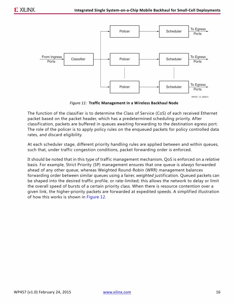
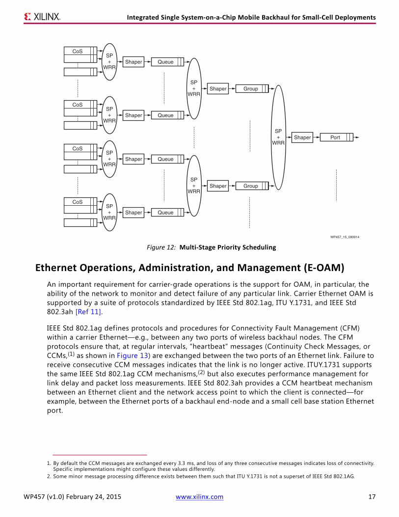
QoS is delivered by a traff ic management process such as shown in Figure 11, consisting of a packet classif ier, policer, and a multi-stage scheduler. For example, network maintenance packets can be marked with the highest priority class, and are always scheduled in strict priority, expedited ahead of any large burst of user traffic data such as consumer video data download.
Integrated Single System-on-a-Chip Mobile Backhaul for Small-Cell Deployments
The function of the classif ier is to determine the Class of Service (CoS) of each received Ethernet packet based on the packet header, which has a predetermined scheduling priority. After classif ication, packets are buffered in queues awaiting forwarding to the destination egress port. The role of the policer is to apply policy rules on the enqueued packets for policy controlled data rates, and discard eligibility.
At each scheduler stage, different priority handling rules are applied between and within queues, such that, under traff ic congestion conditions, packet forwarding order is enforced.
It should be noted that in this type of traff ic management mechanism, QoS is enforced on a relative basis. For example, Strict Priority (SP) management ensures that one queue is always forwarded ahead of any other queue, whereas Weighted Round-Robin (WRR) management balances forwarding order between similar queues using a fairer, weighted justif ication. Queued packets can be shaped into the desired traff ic profile, or rate-limited; this allows the network to delay or limit the overall speed of bursts of a certain priority class. When there is resource contention over a given link, the higher-priority packets are forwarded at expedited speeds. A simplif ied illustration of how this works is shown in Figure 12.
X-Ref Target - Figure 11
Figure 11: Traffic Management in a Wireless Backhaul NodeWP457_14_090914
Integrated Single System-on-a-Chip Mobile Backhaul for Small-Cell Deployments
Ethernet Operations, Administration, and Management (E-OAM)An important requirement for carrier-grade operations is the support for OAM, in particular, the ability of the network to monitor and detect failure of any particular link. Carrier Ethernet OAM is supported by a suite of protocols standardized by IEEE Std 802.1ag, ITU Y.1731, and IEEE Std 802.3ah [Ref 11].
IEEE Std 802.1ag defines protocols and procedures for Connectivity Fault Management (CFM) within a carrier Ethernet—e.g., between any two ports of wireless backhaul nodes. The CFM protocols ensure that, at regular intervals, “heartbeat” messages (Continuity Check Messages, or CCMs,(1) as shown in Figure 13) are exchanged between the two ports of an Ethernet link. Failure to receive consecutive CCM messages indicates that the link is no longer active. ITUY.1731 supports the same IEEE Std 802.1ag CCM mechanisms,(2) but also executes performance management for link delay and packet loss measurements. IEEE Std 802.3ah provides a CCM heartbeat mechanism between an Ethernet client and the network access point to which the client is connected—for example, between the Ethernet ports of a backhaul end-node and a small cell base station Ethernet port.
1. By default the CCM messages are exchanged every 3.3 ms, and loss of any three consecutive messages indicates loss of connectivity. Specif ic implementations might configure these values differently.
2. Some minor message processing difference exists between them such that ITU Y.1731 is not a superset of IEEE Std 802.1AG.
Integrated Single System-on-a-Chip Mobile Backhaul for Small-Cell Deployments
Figure 13 shows that there is more than one level of connectivity management. Level 7 typically represents the customer level—for example, an end-node (e.g., MEP1) at the 4G base station site—and the core network node in the wireless service provider network. Additional levels (up to 7) are the backhaul and transport network service provider levels—for example, Level 0, as shown between MEP2 and MEP3. Within each level, connectivity between MEPs might be within one network operator domain or between one or more links connecting operator domains. Each pair of maintenance end-points at the same level (for example, MEP1 and MEP5) exchange CCM heartbeats and are able to detect (by way of CCM messages), monitor, validate through Loopback and Link Trace, and alert to the loss of connectivity between MEPs.
The protocols also allow for Maintenance Intermediate Point (MIP) nodes, which have limited functionality compared to MEP nodes. A MIP node transparently performs forwarding of any IEEE Std 802.1ag/Y.1731 message traffic it receives, but it does not exchange CCM heartbeat messages with other nodes in the network.
X-Ref Target - Figure 13
Figure 13: CCM Message Exchange between Ethernet NodesWP457_16_090914
MEP1 MEP5
CCM (each 3.3ms)
CCM: Continuity Check MessageMEP: Maintenance End-PointMIP: Maintenance Intermediate Point
Integrated Single System-on-a-Chip Mobile Backhaul for Small-Cell Deployments
Automatic Protection Switching (APS)APS provides the mechanism that allows the carrier Ethernet to reconfigure the network and recover from link faults detected by Ethernet-OAM, and from hardware and software failures by other mechanisms. Ethernet Ring Protection Switching (ERPS)[Ref 6] defines a network link’s redundant ring-topology architecture. It supports protocols that match the reliability and recovery speed (e.g., within 50 ms) of the traditional SONET/SDH network architecture.
The ERPS network architecture is shown in Figure 14; it closely follows the traditional SONET/SDH architecture. Three or more network nodes form a ring topology. Two such rings are interconnected to form larger networks; each network ring can belong to a different network operator.
Figure 15 demonstrates the network protection mechanism in ERPS. In normal operation, MEP pairs exchange heartbeats (i.e., CCM messages) over each link.
X-Ref Target - Figure 14
Figure 14: Ethernet Ring Topology
X-Ref Target - Figure 15
Figure 15: Ethernet Ring Protection Switching (ERPS) and Link Failure Reconfiguration
Integrated Single System-on-a-Chip Mobile Backhaul for Small-Cell Deployments
Within a ring, there is a link designated as a Ring Protection Link (RPL). To prevent an undesirable loop from occurring, this RPL is blocked by the RPL Owner to normal traff ic; however, it is not blocked to heartbeats (CCMs). This initial default configuration is shown in Figure 15(a). For each node in the ring architecture, therefore, there is at least one redundant link . In a fully configured ring, this redundancy guarantees that each node in the ring, and any external network(s) connected to the ring, can still be reached in the event of a link failure.
Detection of a link failure is shown in Figure 15(b); the ERPS protocol causes ring protection Signal Fail messages to be exchanged across the network. The failed link’s RPL Owner then unblocks the RPL (Figure 15(c)), and this reserved (redundant) link takes over normal traffic forwarding. Each node within the network reconfigures its forwarding tables so that full network functionality can be restored, as shown in Figure 15(d).
Synchronization and TimingWireless backhaul networks based on carrier Ethernet can support accurate frequency and time synchronization, and thus meet the stringent requirements of mobile networks. By design, RF signals at the antenna ports of base stations within geographically adjacent cells must be synchronized; this allows user devices to acquire the network quickly, reduces device complexity, limits interference, and ensures key RF performance metrics of the network. There are two kinds of synchronization between cells:
• Frequency Synchronization: Multiple cells synchronize to a common frequency, and a common clock period is used across all cells; the phase of the clock, however, can differ between cells.
• Time Synchronization: Clock cycles can be regulated to a unique, common phase. When this phase is locked onto a common system time, i.e., absolute time-of-day (ToD), usually based on UTC, similar processing events occur at the same time across cells—for example, transmission of control channel information and frame boundaries.
Both synchronization types are relevant to 4G mobile networks and, in particular, to small cells. As shown in Table 5, TD-SCDMA, CDMA, LTE-TDD, and LTE-Advanced networks all require both accurate frequency and ToD synchronization. At the air-interface antenna port, the signal transmission and reception must be aligned to 50–100 parts per billion (ppb).(1) Across adjacent cells, the ToD synchronization must be within ±1.5 microseconds in order to support various advanced interference coordination features.
• Packet-Based Synchronization. In a network with numerous small cells, the traditional synchronization at the base station, supported by GPS and TDM links such as a leased T1/E1 line, are not cost-effective options. This has led to the development of packet-based synchronization methods, i.e., IEEE Std 1588v2 Precision Timing Protocol (PTP)[Ref 7]. In conjunction with Synchronous Ethernet (SyncE) [Ref 12], IEEE Std 1588v2 has become mandatory in small-cell applications, and could also be required in macro-cell deployments with or without GPS.
1. That typically needs to be supported by 16 ppb frequency accuracy at the network interface of the base station if the frequency signal is provided externally.
Integrated Single System-on-a-Chip Mobile Backhaul for Small-Cell Deployments
IEEE Std 1588v2 can be utilized as shown in Figure 16. To minimize packet delay variations (PDV) between an IEEE Std 1588v2 master clock and a slave clock in a packet network, it is preferable to locate the master clock as physically close as possible to the slave clock (e.g., a 1-hop distance is shown in the f igure), because these two clocks must be tightly synchronized. The master clock and each slave clock are synchronized in these steps:
1. The master sends a Sync message, as shown in Figure 16(b), which contains its origin time.
2. The slave exchanges delay measurements with the master.
3. The slave clock is adjusted by the clock (T ) difference and the measured path delay (D).
As shown in Figure 16(a), the master clock can be located on the backhaul aggregation node or a base station, which can source a high-precision timing reference. The slave clock can be located on the end-node, within a number of forwarding hops that has been reduced as much as possible. In this fashion, an optimum balance between timing accuracy and cost of reference clocks can be achieved.
Table 5: Synchronization Requirements of 3GPP Mobile Networks
Radio Access Technology
Frequency Accuracy (Network/Air Interface)
Absolute Phase Accuracy with Minimum 8-Hour Holdover
Integrated Single System-on-a-Chip Mobile Backhaul for Small-Cell Deployments
Xilinx Support for the Mobile Backhaul With its families of All Programmable FPGAs and SoCs, Xilinx is recognized as a leading supplier to the wireless infrastructure industry. These devices are used extensively in mobile wireless base stations, wireless and wired backhaul, and radio units. Xilinx and its partners continue to provide an extensive set of programmable logic IP cores that can support an integrated wireless backhaul solution, including both the wireless modem and the carrier Ethernet switching functionality.
The semiconductor products supporting wireless backhaul include Kintex®-7 and Kintex UltraScale FPGAs, and Zynq®-7000 All Programmable (AP) SoCs.[Ref 13][Ref 14][Ref 15] The Kintex-7 and Kintex UltraScale families comprise traditional FPGAs that contain from 65,000 to 1,160,000 logic cells, DSP slices that can perform up to 2.7 million GMACs, internal memory blocks, and a variety of I/O interfaces. The FPGA logic can be programmed to support all the digital functions—for example, packet processing, traff ic management, modem, and I/O interfaces.
The capability of the Zynq-7000 AP SoC to integrate a complete wireless backhaul solution is demonstrated in the reference design of Figure 17. A single Zynq-7000 device can support all the following:
• The application software, implemented in the Zynq-7000 AP SoC Processor System (PS) on a dual-core ARM Cortex-A9 processor
• The backhaul functionality, including timing and synchronization, packet switching, and wireless modem, implemented in the Zynq-7000 AP SoC Programmable Logic (PL)(1)
• The interfaces, including 1 GbE and 10 GbE MAC/PCS interfaces, analog interfaces such as JESD204B or LVDS, also implemented in the Zynq-7000 AP SoC PL
The programmability of Xilinx devices enables a common silicon platform to support multiple wireless backhaul solutions with different interfaces, capacities, and features. This compares favorably with a typical multi-chip design of a CPU, a dedicated packet switch, and a wireless modem. For a complete solution, the board designer needs only to complete the analog design and equip the board with the necessary oscillators and (optional) PLLs. A GPS module is required when the wireless backhaul node is also providing master timing to the rest of the network.
1. The PS and PL are interconnected by high-speed AXI interfaces.
Integrated Single System-on-a-Chip Mobile Backhaul for Small-Cell Deployments
Zynq-7000 AP SoC Processor System (PS)In order to improve the real-time response of software tasks, the OS can be upgraded with some real-time support (e.g., RT_PreEmpt for Linux). One core can be devoted to applications that require potential real-time response such as Ethernet OAM (IEEE Std 802.1ag/Y.1731) and Ethernet APS (ERPS G.8032), all of which can also be enhanced by OS interrupt shielding, scheduler hardening, and thread aff inity. In cases where the radio control requires predictable-time response, it can also be scheduled on this core.
The PS supports a set of interfaces to memory and I/O that meet the requirements of almost all scenarios. For example, in a typical wireless backhaul node, local management access to the processor system is needed, which can be supported by the built-in GbE MAC block. The AXI interconnect between the PS and PL support four general-purpose ports (GP), which can used for I/O access to the PL, and four high-performance ports (HP) for priority-enabled, high-speed data transfers.
Zynq-7000 AP SoC Programmable Logic (PL)The PL offers full flexibility for the design of packet processing and wireless modem functionalities. This enables, for instance, tuning the packet processing implementation for the required features to minimize logic resource utilization. For example, in a carrier Ethernet environment, MAC address learning might not be needed, but can be instead statically configured. The number of ports, queues, and scheduler stages can be programmed to meet the requirements. Additionally, support for Ethernet OAM and ERPS might be implemented only on some specif ic variants of the products.
The Zynq-7000 family offers a range of SoCs with increasing logic resources, enabling maximum flexibility to support different capacities and modem configurations. For example, the radio link aggregation (RLAG) function is dependent on the supported capacity and number of modems. With fewer modem instances, a smaller device can be used. The RLAG function might include features such as packet header compression, payload compression, and radio link bonding.
Xilinx provides highly competitive wireless modem IP cores for both E-band and microwave radios. These include LDPC and RS forward error correction (FEC) IP cores and the transmit/receive digital modules. XPIC and MIMO can be supported though the integration of multiple modem instances.
Packet Processing and SwitchThe 10 Gb/s L2 switch reference design shown in Figure 19 includes the packet pre-processor, the traff ic manager, and the packet post-processor.
• The pre-processor performs packet parsing and classif ication to ensure ingress Ethernet packets are sorted into the correct queues. It can also implement additional functions, such as searching for specif ic packet parameters, or enforcing traff ic class policy rules.
• The traffic manager contains a large number of packet queues (1K–16K), and processes the packets in multiple scheduling stages, including functions such as policing, packet dropping, priority handling, and traff ic shaping.
• The post-processor can modify the egress packets before they are sent out of the switch, for example, to recalculate the CRC.
Integrated Single System-on-a-Chip Mobile Backhaul for Small-Cell Deployments
The reference design also implements SyncE with frequency recovery from multiple ingress transceivers. The special packets that cannot be processed in the PL—for example, SyncE ESMC channel (SSM) messages—are extracted and processed in the PS (shown as Pkt_to_CPU block). Similarly, IEEE Std 1588v2 packets are forwarded to the precision timing protocol (PTP) processor. Ethernet OAM and ERPS packets are also processed. For example, continuity check “heartbeat” messages (CCMs) are handled in the PL, and possibly forwarded to the PS to support message types like ERPS, loopback, and link trace.
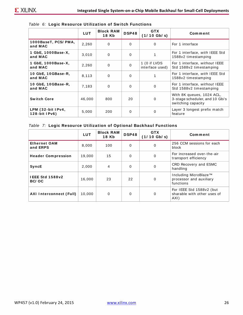
A number of parameters can be selected to align resource utilization to application requirements. These include the number of ports, the access control list (ACL), the number of SyncE ports, the number of Ethernet ports, the ports with IEEE Std 1588v2 timestamping, and the number of queues. The logic resource utilization of the packet processing functions typically included in any wireless backhaul application is provided in Table 6. The logic resource utilization of some additional functions is shown in Table 7; those are optional depending on whether the backhaul unit is an aggregation node, a transport node, or an end-node.
X-Ref Target - Figure 19
Figure 19: Zynq-7000 AP SoC-Based Packet Processing and Switch Reference DesignWP457_22_111814
Integrated Single System-on-a-Chip Mobile Backhaul for Small-Cell Deployments
E-band ModemThe E-band modem IP core reference design illustrated in Figure 20 describes an example of a single Zynq-7000 7-Z100 device implementing a 500 MHz wide band modem in the PL. The design integrates an LDPC-based FEC and half-XPIC capabilities.
The modem is controlled by the PS ARM cores through the AXI interconnect ports. The analog components are also controlled by the ARM cores through the MIO interfaces.
Parallel (LVDS) or serial (JESD204B) interfacing can be considered for DAC/ADC. For 500 MHz bandwidth, a 625 MSPS I/Q interface can be used for the transmit path (with further oversampling in the DAC), with an 880 MSPS I/Q interface on the receive path. Assuming 16-bit data and JESD204B, this could be supported by four serial transceivers at 10 Gb/s (Tx and Rx paths sharing the same transceivers).
An optional transmitter feedback interface can be implemented for calibration purposes. A number of 1/10GbE interfaces are also required when packet processing functionality is integrated.
X-Ref Target - Figure 20
Figure 20: Zynq-7000 AP SoC E-band Modem Reference Design
Zynq-7000 AP SoC ARM CPU Cores
WP457_23_111814
ADC
ADC
V Out H In
10G
bE
MIO
Xilinx Modem IP Packet
Processing IP
Zynq-7000 AP SoC Half XPIC Vertical Modem/Packet Processor S
Integrated Single System-on-a-Chip Mobile Backhaul for Small-Cell Deployments
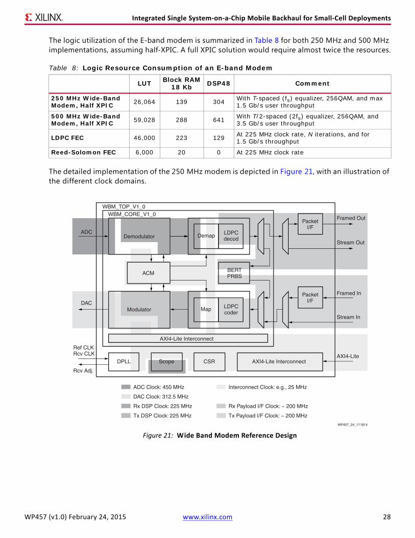
The logic utilization of the E-band modem is summarized in Table 8 for both 250 MHz and 500 MHz implementations, assuming half-XPIC. A full XPIC solution would require almost twice the resources.
The detailed implementation of the 250 MHz modem is depicted in Figure 21, with an illustration of the different clock domains.
Table 8: Logic Resource Consumption of an E-band Modem
LUT Block RAM18 Kb DSP48 Comment
250 MHz Wide-Band Modem, Half XPIC 26,064 139 304 With T-spaced (fs) equalizer, 256QAM, and max
1.5 Gb/s user throughput
500 MHz Wide-Band Modem, Half XPIC 59,028 288 641 With T/2-spaced (2fs) equalizer, 256QAM, and
3.5 Gb/s user throughput
LDPC FEC 46,000 223 129 At 225 MHz clock rate, N iterations, and for 1.5 Gb/s throughput
Reed-Solomon FEC 6,000 20 0 At 225 MHz clock rate
X-Ref Target - Figure 21
Figure 21: Wide Band Modem Reference DesignWP457_24_111814
Integrated Single System-on-a-Chip Mobile Backhaul for Small-Cell Deployments
Integrated Packet Processing and Modem SolutionA complete wireless backhaul solution, integrating packet processing, radio link aggregation and modem can be integrated in a single Zynq device as shown in Table 9.
As can be seen, there is still quite a large amount of resource available; hence, the solution could be extended to a complete small-cell application—for example, integrating the radio functionality and/or part of the baseband processing.
ConclusionThis white paper describes the evolution of and solutions for wireless backhaul, with a focus on supporting 3G/4G small cells with E-band radio. It is shown that carrier Ethernet based wireless backhaul has advanced to a stage where it can eff iciently and cost-effectively support large scale deployments of small cells. Solutions based on Ethernet standards enable backhaul transport, QoS, and network reliability, whereas E-band radio supports densely sited spectrum and high-capacity links.
Xilinx All Programmable FPGA and SoC devices are shown to support a high level of flexibility suitable for small cell implementation, given the potential variability in throughput, form-factor, and cost sensitivity.
Xilinx also provides IP cores that support the key functions required for wireless backhaul, including those for packet processing, radio link aggregation, and the modem.
Table 9: Example: Single Zynq-7000 AP SoC Digital Solution for E-band Backhaul
LUT Block RAM 18 Kb DSP48 GTX Comment
L2 Switch and Interfaces 53,983 256 20 2
One each 1000BaseT, GbE, and 10GbE interface, low capacity switch, and Ethernet OAM/ERPS
RLAG 21,000 19 0 Header compression, SyncE, etc.
250 MHz Wide- Band Modem 72,064 362 433 6 1.5 Gb/s throughput, LDPC FEC, Serial
(JESD204B) interface to ADC/DAC
Estimated Total Resource 147,047 637 453 8 Resource estimates vary with capacity
2. Small Cell Forum, Small Cell Market Status, February 2013, www.smallcellforum.org/smallcellforum_resources/pdfsend01.php?file=050-SCF_2013Q1-market-status_report.pdf
3. IEEE Std 802.3at-2009, Part3: CSMA/CD Access Method and Physical Layer Specification Amendment 3: DTE Power via MDI Enhancements, IEEE Std Computer Society
4. IEEE Std 802.1ag, Standard for Local and Metropolitan Area Networks: Virtual Bridged Local Area Networks Amendment 5: Connectivity Fault Management, IEEE Std Computer Society
5. ITU-T Y.1731-2011: OAM Functions and Mechanisms for Ethernet Based Networks, ITU-T Recommendation, Telecommunications Standardization Sector of ITU
6. ITU-T G.8032-2008, Ethernet Ring Protection Switching, ITU-T Recommendation, Telecommunications Standardization Sector of ITU
7. IEEE Std 1588-2008, Standard for a Precision Clock Synchronization Protocol for Networked Measurement and Control Systems, IEEE Std Instrumentation and Measurement Society
8. FCC, Part 101, PART 101–Fixed Microwave Services (47CFR101)9. Ericsson Review No. 02, 2009, Hansryd & Eriksson, High-Speed Mobile Backhaul Demonstrators
www.ericsson.com/ericsson/corpinfo/publications/review/2009_02/files/Backhaul.pdf 10. Next Generation Mobile Networks Alliance, Guidelines for LTE Backhaul Traffic Estimation, 3rd
July 2011, http://www.ngmn.org/uploads/media/NGMN_Whitepaper_Guideline_for_LTE_Backhaul_Traff ic_Estimation.pdf
11. IEEE Std 802.3ah-2004, Part3: CSMA/CD Access Method and Physical Layer Specif ication Amendment 3: MAC Parameters, Physical Layers, and Management Parameters for Subscriber Access Networks, IEEE Std Computer Society
12. ITU-T G.8262, Timing Characteristics of Synchronous Ethernet Equipment Slave Clock , ITU-T Recommendation, Telecommunications Standardization Sector of ITU
13. Xilinx, Kintex-7 FPGA Product Brief14. Xilinx, DS892, Kintex UltraScale Architecture Data Sheet: DC and AC Switching Characteristics15. Xilinx, XMP087, Zynq®-7000 All Programmable SoCs Product Table
Integrated Single System-on-a-Chip Mobile Backhaul for Small-Cell Deployments
Revision HistoryThe following table shows the revision history for this document:
DisclaimerThe information disclosed to you hereunder (the “Materials”) is provided solely for the selection and use of Xilinxproducts. To the maximum extent permitted by applicable law: (1) Materials are made available “AS IS” and with all faults,Xilinx hereby DISCLAIMS ALL WARRANTIES AND CONDITIONS, EXPRESS, IMPLIED, OR STATUTORY, INCLUDING BUT NOTLIMITED TO WARRANTIES OF MERCHANTABILITY, NON-INFRINGEMENT, OR FITNESS FOR ANY PARTICULAR PURPOSE;and (2) Xilinx shall not be liable (whether in contract or tort, including negligence, or under any other theory of liability)for any loss or damage of any kind or nature related to, arising under, or in connection with, the Materials (including youruse of the Materials), including for any direct, indirect, special, incidental, or consequential loss or damage (including lossof data, profits, goodwill, or any type of loss or damage suffered as a result of any action brought by a third party) evenif such damage or loss was reasonably foreseeable or Xilinx had been advised of the possibility of the same. Xilinxassumes no obligation to correct any errors contained in the Materials or to notify you of updates to the Materials or toproduct specif ications. You may not reproduce, modify, distribute, or publicly display the Materials without prior writtenconsent. Certain products are subject to the terms and conditions of Xilinx’s limited warranty, please refer to Xilinx’sTerms of Sale which can be viewed at http://www.xilinx.com/legal.htm#tos; IP cores may be subject to warranty andsupport terms contained in a license issued to you by Xilinx. Xilinx products are not designed or intended to be fail-safeor for use in any application requiring fail-safe performance; you assume sole risk and liability for use of Xilinx productsin such critical applications, please refer to Xilinx’s Terms of Sale which can be viewed at http://www.xilinx.com/legal.htm#tos.
Automotive Applications DisclaimerXILINX PRODUCTS ARE NOT DESIGNED OR INTENDED TO BE FAIL-SAFE, OR FOR USE IN ANY APPLICATION REQUIRINGFAIL-SAFE PERFORMANCE, SUCH AS APPLICATIONS RELATED TO: (I) THE DEPLOYMENT OF AIRBAGS, (II) CONTROL OF AVEHICLE, UNLESS THERE IS A FAIL-SAFE OR REDUNDANCY FEATURE (WHICH DOES NOT INCLUDE USE OF SOFTWARE INTHE XILINX DEVICE TO IMPLEMENT THE REDUNDANCY) AND A WARNING SIGNAL UPON FAILURE TO THE OPERATOR, OR(III) USES THAT COULD LEAD TO DEATH OR PERSONAL INJURY. CUSTOMER ASSUMES THE SOLE RISK AND LIABILITY OFANY USE OF XILINX PRODUCTS IN SUCH APPLICATIONS.
Date Version Description of Revisions02/24/2015 1.0 Initial Xilinx release.