Page 1
HORIZON H2020-ICT-2014-1
Objective ICT-09-2014: Topics and Methods for Software Development
A novel reconfigurable by design highly distributed applications
development paradigm over programmable infrastructure
D3.3 — Integrated Smart Controller Implementation v1
Editors: Panagiotis Gouvas, Anastasios Zafeiropoulos (UBITECH)
Contributors:
Costantinos Vassilakis, Eleni Fotopoulou (UBITECH), M.
Repetto (CNIT), N. Koutsouris (WINGS), T. Quang (TUB), J.
Sterle (UL), S. Siravo (MAGGIOLI), G. Kioumourtzis
(ADITESS), L. Porwol (NUIG)
Date: 17 August 2016
Version: 1.0
Status: Final
Work Package: WP3—Smart Controller Reference Implementation
Classification: Public
Ref. Ares(2016)4468092 - 17/08/2016
Page 2
D3.3 – Integrated Smart Controller Implementation v1
2 / 26
ARCADIA Profile
Partners
Insight Centre for Data Analytics, National University of Ireland, Galway
Ireland
Stiftelsen SINTEF Norway
Technische Universität Berlin Germany
Consorzio Nazionale Interuniversitario per le Telecomunicazioni
Italy
Univerza v Ljubljani Slovenia
UBITECH Greece
WINGS ICT Solutions Information & Communication Technologies EPE
Greece
MAGGIOLI SPA Italy
ADITESS Advanced Integrated Technology Solutions and Services Ltd
Cyprus
Grant Agreement No.: 645372
Acronym: ARCADIA
Title: A NOVEL RECONFIGURABLE BY DESIGN HIGHLY DISTRIBUTED APPLICATIONS
DEVELOPMENT PARADIGM OVER PROGRAMMABLE INFRASTRUCTURE
URL: http://www.arcadia-framework.eu/
Start Date: 01 January 2015
Duration: 36 months
Page 3
D3.3 – Integrated Smart Controller Implementation v1
3 / 26
Document History
Version Date Author (Partner) Remarks
0.1 15 June 2016 P. Gouvas, A. Zafeiropoulos (UBITECH)
Added table of contents
Added executive summary
0.2 29 June 2016 P. Gouvas, A. Zafeiropoulos, C. Vassilakis, E. Fotopoulou
(UBITECH)
Added description of components
0.3 29 July 2016 M. Repetto (CNIT), C. Vassilakis, A. Zafeiropoulos (UBITECH), N. Koutsouris (WINGS), T. Quang (TUB), J. Sterle (UL), S. Siravo (MAGGIOLI), G. Kioumourtzis (ADITESS), L. Porwol (NUIG)
Updated description of components
Added introduction and conclusion
Finalised formatting
0.4 10 August 016 G.Kioumourtzis (ADITESS) Internal review
1.0 17 August 2016 Panagiotis Gouvas (UBITECH) Finalised document
Page 4
D3.3 – Integrated Smart Controller Implementation v1
4 / 26
Executive Summary
ARCADIA aims to provide a novel development paradigm needed to take advantage of the emerging
programmability of the cloud infrastructure, and hence develop reconfigurable-by-design applications
that support high performance, scalability, failure prevention and recovery, and in general self-
adaptation to changes in the execution environment. The proposed framework relies on the development
of an extensible Context Model which will be used by developers to produce annotated source-code and
generate distributed applications as service chains of application tiers and network functions containing
meaningful semantics. A Smart Controller responsible for on-boarding the HDAs is undertaking the tasks
of translating annotations to optimal infrastructural configuration. Such a controller is enforcing an
optimal configuration to the registered programmable resources and is pro-actively adjusting the
configuration plan based on the Infrastructural State and the Application State to meet objectives and
apply policies. Driving a distributed application through its entire lifetime proves highly beneficial for all
stakeholders since the synergy of the introduced applications’ re-configurability and the underlying
infrastructure’s programmability, facilitates the development of new fine-grained strategies able to fulfil
new and complex requirements.
This deliverable describes the implementation of the first integrated version of the ARCADIA Smart
Controller. The deliverable consists of a short description of the development activities and
implementation status, along with the source code of the integrated version of the Smart Controller. It is
intended for readers with experience in cloud computing and software engineering, as well as, familiarity
with the initial architecture design.
It should be noted that the current version of the ARCADIA Smart Controller is going to be used for the
first round of implementation of the ARCADIA use cases in WP5, while a final version of the ARCADIA
Smart Controller is envisaged to be provided by M24 of the project.
Page 5
D3.3 – Integrated Smart Controller Implementation v1
5 / 26
Table of Contents
1 Introduction.............................................................................................................................. 7
1.1 Purpose and Scope ................................................................................................................................. 7
1.2 Relation with other WPs ...................................................................................................................... 7
2 The ARCADIA Framework .................................................................................................... 8
3 Integrated version of SMART Controller ........................................................................ 9
3.1 Short Description of each Smart Controller Module ............................................................... 10
3.2 Overlay Networking Module............................................................................................................. 17
4 Conclusions ............................................................................................................................ 25
5 References .............................................................................................................................. 26
List of Figures
Figure 1 — ARCADIA Framework Overview .......................................................................................................................... 8
Figure 2 – Overall components of the orchestrator ......................................................................................................... 10
Figure 3 – Agent Module ............................................................................................................................................................... 11
Figure 4 – Annotation Interpreter............................................................................................................................................ 11
Figure 5 – Available Annotations .............................................................................................................................................. 12
Figure 6 – Automated Generation of Agent Business Logic .......................................................................................... 12
Figure 7 – API definitions ............................................................................................................................................................. 13
Figure 8 – Smart Controller Entry Point ................................................................................................................................ 13
Figure 9 – Policy Enforcement Engine ................................................................................................................................... 14
Figure 10 – IaaS Adapters’ module .......................................................................................................................................... 15
Figure 11 – Core Orchestrator Logic ....................................................................................................................................... 15
Figure 12 – Business Logic for three Repositories ........................................................................................................... 16
Figure 13 – REST Layer of all modules................................................................................................................................... 16
Figure 14 – Unikernel Management ........................................................................................................................................ 16
Figure 15 – General-purpose Business Logic ...................................................................................................................... 17
Figure 16 – Creation & initialization of an OOR VM instance for overlay networking – Part 1 .................... 19
Figure 17 – Creation & initialization of an OOR VM instance for overlay networking – Part 2 .................... 20
Figure 18 – Creation & initialization of an OOR VM instance for overlay networking – Part 3 .................... 21
Figure 19 – Initialisation of a graph instance that represents a graph’s leaf – Part 1 ....................................... 22
Figure 20 – Initialisation of a graph instance that represents a graph’s leaf – Part 2 ....................................... 23
Figure 21 – Initialisation of a graph instance that represents a graph’s leaf – Part 3 ....................................... 24
Page 6
D3.3 – Integrated Smart Controller Implementation v1
6 / 26
Acronyms
API Application Programming Interface
CAE Cloud Applications Embedding
DoW Description of Work
HDA Highly Distributed Application
IaaS Infrastructure as a Service
JVM Java Virtual Machine
LXC Linux Container
NFV Network Function Virtualisation
NFVI Network Functions Virtualisation Infrastructure
NV Network Virtualisation
OS Operating System
PM Physical Machine
PoP Point of Presence
QoS Quality of Service
SDN Software Defined Networking
VDCE Virtual Data Centre Embedding
VLAN Virtual Local Area Network
VNE Virtual Network Embedding
VNF Virtual Network Function
VPN Virtual Private Network
WP Work Package
Page 7
D3.3 – Integrated Smart Controller Implementation v1
7 / 26
1 Introduction
1.1 Purpose and Scope
This deliverable provides details with regards to the first version of the integrated ARCADIA Smart
Controller implementation, based on the development status at M18 of the project. It actually builds upon
the results presented at D3.1 [1], where the implementation status of the discrete components of the
ARCADIA Smart Controller were provided at M15 of the project. Further information concerning the
updated implementation status per component along with information concerning the overall
integration activities are given.
The ARCADIA Smart Controller is responsible for the deployment of distributed applications over the
available programmable infrastructure and their management during the execution time, triggering re-
configurations where required based on the defined optimization objectives and policies, on behalf of the
application developer and the services provider. It consists of a set of components covering deployment
aspects, optimisation aspects during deployment and runtime, policies enforcement during runtime,
management of the available compute, storage and network resources, application packaging,
networking and monitoring and analysis functionalities.
Upon the specification and the initial development of each component, a set of integration activities were
realised for providing the first version of the ARCADIA Smart Controller. This version supports a service
graph placement over programmable infrastructure along with the application of deployment and
runtime policies, the management of the available networking and computational resources and the
execution of set of monitoring and data management mechanisms. The set of components and
mechanisms developed are totally in line with the specification provided in D2.3 that regards the
description of the ARCADIA framework.
Given the type of the deliverable is “Other” and it mainly refers to the delivery of the developed software,
the current document is considered as accompanying material providing details with regards to the
source code development, the organization and management of the ARCADIA Github repository and the
main functionalities and interconnection interfaces provided per component. The current version is
going to be updated in order to produce the final version, following the release of the final integrated
Smart Controller implementation at M24 of the project.
1.2 Relation with other WPs
This deliverable is provided within the framework of WP3, however the provided results are going to be
exploited by other WPs and mainly by WP4 – “ARCADIA Development Toolkit” and WP5 – “Use Cases
Implementation and Evaluation”. In WP4, the ARCADIA Smart Controller is interconnected with the
developed Web IDE plugin, facilitating the automated submission of distributed applications developed
based on the ARCADIA software development paradigm to the ARCADIA Repository, where service
graphs may be instantiated and orchestrated -over the registered programmable infrastructure- by the
Smart Controller.
Furthermore, the release of the first version of the integrated Smart Controller is crucial for WP5
activities. Specifically, the first phase of implementation of the ARCADIA use cases that is going to be
completed by M24 of the project is going to be based on the first version of the Smart Controller. Feedback
from the deployments in the three ARCADIA use cases will be also provided to WP3 for
improvements/extensions towards the release of the final version of the integrated Smart Controller.
Page 8
D3.3 – Integrated Smart Controller Implementation v1
8 / 26
2 The ARCADIA Framework
In this section, we briefly recall the architecture of the ARCADIA Framework and the role of the Smart
Controller.
The ARCADIA framework consists of a set of components covering in a holistic way the development,
deployment and management of applications in runtime over the available programmable infrastructure.
A high level overview of the ARCADIA framework is provided in Figure 1 (including some implementation
specific indications). In the upper level of the framework, a set of components are made available for
designing, developing and deploying HDAs. The set of components are used by software developers
towards the development of applications following the ARCADIA software development paradigm, as
well as service providers towards the design of services graphs along with their mapping with policies.
In the middle level of the framework, the ARCADIA Smart Controller deploys the applications over the
available programmable infrastructure and manages the application during the execution time triggering
re-configurations where required based on the defined optimization objectives and policies, on behalf of
the application developer and the services provider. In the lower level of the framework, management of
the available compute, storage and network resources is realized along with establishment of the
required monitoring and signaling probes for the real-time management of the instantiated components
and links.
Figure 1 — ARCADIA Framework Overview
Page 9
D3.3 – Integrated Smart Controller Implementation v1
9 / 26
Following, we are providing more details with regards to the components included in the ARCADIA Smart
Controller. In more detail, the Smart Controller includes the following components: (i) the Deployment
Manager that is responsible for the complex task of undertaking the deployment model instance and
“translating” it into optimal deployment configuration taking under consideration the registered
programmable resources, the current situation in the deployment ecosystem and the applied policies;
(ii) the Optimisation Engine that proactively adjusts of the running configuration as well as reactively
triggers re-configurations in the deployment plan, based on measurements that derive from the
monitoring components of the Smart Controller (Monitoring and Analysis Engine) and the existing
policies as provided by the Policy Enforcement component. The ultimate goals of the Optimisation Engine
are two: a) zero-service disruption and b) re-assurance of optimal configuration across time; (iii) the
Policy Enforcement component which assures that the imposed policies on behalf of the Service Provider
are adhered across the applications operational lifecycle; (iv) the Execution Manager that is responsible
for the execution of the deployment plan based on the instantiation of the required components and the
links among them, according to the denoted service graph in the deployment script. The Execution
Manager is also responsible for implementing the monitoring mechanisms required per component and
service graph for the collection of the information required by the denoted monitoring hooks. Such
information is then provided to the Monitoring and Analysis Engine for further processing; (v) the
Programmable Resource Manager that exposes a specific interface where programmable resources are
registered and managed (reserved/released). Programmable resources can span from configured IaaS
frameworks, programmable physical switching/routing equipment, programmable firewalls, application
servers, modularized software entities (databases, HTTP proxies etc.). Allocation/Release of resources is
realised upon requests provided by the Deployment Manager; (vi) the Monitoring and Analysis Engine
that is responsible for collecting the required information –as defined by the monitoring hooks per
component and service graph- and supporting the extraction of insights and predictions upon analysis.
The considered software components per service graph are deployed in a multi-IaaS environment along
with the associated mechanisms for supporting signalling and measurement feeds. Monitoring feeds to
these mechanisms are provided based on information collected by the ARCADIA Agent that is included
within each ARCADIA component.
3 Integrated version of SMART Controller
The Smart Controller consists of several subcomponents that reflect the high level architecture that has
been thoroughly described. Although the nature of the deliverable is ‘other’, the purpose of this
deliverable is to provide a companion regarding the navigation to the Smart Controller source code. The
source code is organized using Maven1 technology in order to assure the overall quality of the project.
According to this technology, each separate high level software ‘artefact’ is addressed as module. At
present, the Smart Controller consists of 15 artefacts. We will briefly discuss them in the following
section.
1 https://maven.apache.org/
Page 10
D3.3 – Integrated Smart Controller Implementation v1
10 / 26
3.1 Short Description of each Smart Controller Module
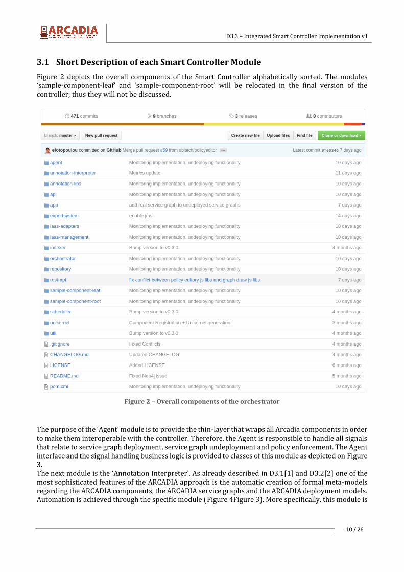
Figure 2 depicts the overall components of the Smart Controller alphabetically sorted. The modules ‘sample-component-leaf’ and ‘sample-component-root’ will be relocated in the final version of the controller; thus they will not be discussed.
Figure 2 – Overall components of the orchestrator
The purpose of the ‘Agent’ module is to provide the thin-layer that wraps all Arcadia components in order to make them interoperable with the controller. Therefore, the Agent is responsible to handle all signals that relate to service graph deployment, service graph undeployment and policy enforcement. The Agent interface and the signal handling business logic is provided to classes of this module as depicted on Figure 3. The next module is the ‘Annotation Interpreter’. As already described in D3.1[1] and D3.2[2] one of the most sophisticated features of the ARCADIA approach is the automatic creation of formal meta-models regarding the ARCADIA components, the ARCADIA service graphs and the ARCADIA deployment models. Automation is achieved through the specific module (Figure 4Figure 3). More specifically, this module is
Page 11
D3.3 – Integrated Smart Controller Implementation v1
11 / 26
responsible to process a binary archive (that is submitted through the ARCADIA IDE) and create formal models. Binary handling introspection techniques are used in order to achieve the goals of the module.
Figure 3 – Agent Module
Figure 4 – Annotation Interpreter
Moreover, the module ‘annotations’ provides all the definitions of the ARCADIA Annotations that can be used during development. Since ARCADIA Annotations are JSR-250 Java annotations2 they are formally Java interfaces that follow a specific syntactic convention according to the aforementioned standard. At present, 14 discrete annotations can be used as depicted on Figure 5.
2 https://www.jcp.org/en/jsr/detail?id=250
Page 12
D3.3 – Integrated Smart Controller Implementation v1
12 / 26
Figure 5 – Available Annotations
Furthermore, beyond the automated generation of the modelling artefacts, that is driven by the annotations and performed by the annotation interpreter, one of the crucial functionalities is the auto-generation of a REST management interface on-top of each component that is deployed as depicted on Figure 6.
Figure 6 – Automated Generation of Agent Business Logic
Page 13
D3.3 – Integrated Smart Controller Implementation v1
13 / 26
During the development of all modules the inversion of control (IOC) principle is heavily used. This practically means that when a module depends to another module the dependency is declared using only its interface. The real binding happens during runtime. This pattern totally decouples the module development yet it raises one consideration; each module has to publish its interface to a common module which is the API module (Figure 7).
Figure 7 – API definitions
The next module is called ‘app’ and it constitutes the entry the point of the entire project (Figure 8). It is
the module that is primarily executed in order to bootstrap the entire Smart Controller. The execution
context along with the initialization parameter binding is performed in the specific module.
Figure 8 – Smart Controller Entry Point
Page 14
D3.3 – Integrated Smart Controller Implementation v1
14 / 26
The next module is addressed as ‘expertsystem’ (Figure 9). As the name denotes, this component
encapsulates a formal expert system based on Drools3. This expert system is used in order to achieve
policy enforcement. In other words, ARCADIA policies are practically transformed in formal expert
system rules that are executed in the engine.
Figure 9 – Policy Enforcement Engine
One of the major benefits of the Smart Controller is its ability to interconnect with multiple IaaS providers
(Figure 10). Resources from multiple providers may be registered and used towards the deployment
process. To do so, the service locator pattern has been used in order to decouple the IaaS-specific
implementation with the API of the IaaS interaction.
3 http://www.drools.org/
Page 15
D3.3 – Integrated Smart Controller Implementation v1
15 / 26
Figure 10 – IaaS Adapters’ module
The core module of the Smart Controller is the ‘orchestrator’ (Figure 11). These modules contains the
implementation of the entire orchestration logic that is required in order to perform service graph
management.
Figure 11 – Core Orchestrator Logic
As already described in D3.1[1] and D3.2[2], the ARCADIA Smart Controller requires three different types
of persistency engines in order to be fully operational. More specifically, it requires one relational
database for transaction-intensive data, one NoSQL repository for scalable storage of “write-once/read-
many” data and one graph database for efficient querying of graphs. All business logic that relates to these
repositories is provided in the repository module (Figure 12).
Page 16
D3.3 – Integrated Smart Controller Implementation v1
16 / 26
Figure 12 – Business Logic for three Repositories
In an analogous manner with the 'api' module, which encapsulates all the public exposable interfaces of
all modules (that can be chained) the rest module (Figure 13) encapsulates the REST business logic of
all modules.
Figure 13 – REST Layer of all modules
Finally, the last two modules are the ‘unikernel’ (Figure 14) and the ‘util’ (Figure 15). On the one hand,
the ‘unikernel’ encapsulates all business logic that related to the lifecycle management of the unikernels
i.e. their generation and their instantiation/management. On the other hand, the ‘util’ module
encapsulates business logic that is considered horizontal (e.g. security handling).
Figure 14 – Unikernel Management
Page 17
D3.3 – Integrated Smart Controller Implementation v1
17 / 26
Figure 15 – General-purpose Business Logic
3.2 Overlay Networking Module
Given that the implementation of overlay networking part is not detailed in D3.1 (it was not available at
that time), we provide some further information regarding the supported functionalities and the
implementation details.
Establishment of communication among nodes in a multiple-IaaS environment and support of routing
among them is based on an overlay routing approach, based on the configuration and adaptation of the
Open Overlay Router (OOR) [3]. The OOR project aims to deliver a flexible and modular open-source
implementation to deploy programmable overlay networks. It leverages on encapsulating overlay-
specific packets into underlay-compatible packets at the edges of the instantiated overlay and route them
over the physical underlying infrastructure. In order to do so, it maps overlay identifiers to underlay
locators and keeps those mappings updated over time. In the current version, OOR uses:
- LISP 4protocol for the control-plane (e.g. mapping retrieval and updating, etc);
- NETCONF5/YANG6 for the management-plane (e.g. overlay identifiers provisioning, etc);
- can use both LISP and VXLAN-GPE headers for encapsulation.
Overlay network creation
Before placing a service graph, an OOR instance must be created and initialized in order to establish the
underlying logical connections. Therefore, in each involved IaaS, at least one OOR instance must be
operational so as to pass internal traffic. The initialisation steps include:
1. the creation of a new tenant or the use of an existing one (see Figure 16- method createTenant());
2. the creation of a new network or the use of an existing one (see Figure 16 - method
createNetwork());
4 Locator/ID Separation Protocol (LISP), http://www.cisco.com/c/en/us/products/ios-nx-os-
software/locator-id-separation-protocol-lisp/index.html
5 https://tools.ietf.org/html/rfc6241
6 https://tools.ietf.org/html/rfc6020
Page 18
D3.3 – Integrated Smart Controller Implementation v1
18 / 26
3. the creation of a new subNet and its addition to the above network or the use of an existing one
(see Figure 17 method createSubNet());
4. the creation of a new logical router, or the use of an existing one, for IaaS central management
purposes (see Figure 17 method createLogicalRouter());
5. the creation of a new security group, or the use of an existing one, so as to create traffic rules for
our instances (see Figure 18 method createSecGroup());
6. the creation of the OOR instance and the update of its configuration file to include the above
created subnetworks and MS/MR address or the use of an existing instance (see Figure 18
method createVMInstance()).
As soon as the instance is created and the communication links are updated, the overlay network has
been established.
Service Graph Placement
For the service graph placement, a set of further steps are required. These steps include the initialization
of a finite number of unikernel instances that represent the actual implementation of the various services
constructed in Arcadia's’ graph editor, as follows:
1. the initialization of the grounded service (see Figure 19 method initialize());
2. the creation of the vm instance (see Figure 19 method createVMInstance());
3. the upload of the required payload to the created instance-overlay net (see Figure 20 method
uploadPayLoadToVM());
4. the initialization of the Arcadia’s vm signaling protocol (see Figure 20 method
initializeVMSignalingHandlerAgent() and Figure 21method startSignalingProtocol()).
Page 19
Figure 16 – Creation & initialization of an OOR VM instance for overlay networking – Part 1
Page 20
D3.3 – Integrated Smart Controller Implementation v1
20 / 26
Figure 17 – Creation & initialization of an OOR VM instance for overlay networking – Part 2
Page 21
D3.3 – Integrated Smart Controller Implementation v1
21 / 26
Figure 18 – Creation & initialization of an OOR VM instance for overlay networking – Part 3
Page 22
D3.3 – Integrated Smart Controller Implementation v1
22 / 26
Figure 19 – Initialisation of a graph instance that represents a graph’s leaf – Part 1
Page 23
D3.3 – Integrated Smart Controller Implementation v1
23 / 26
Figure 20 – Initialisation of a graph instance that represents a graph’s leaf – Part 2
Page 24
D3.3 – Integrated Smart Controller Implementation v1
24 / 26
Figure 21 – Initialisation of a graph instance that represents a graph’s leaf – Part 3
Page 25
4 Conclusions
This deliverable described the first version of the implementation of the integrated ARCADIA Smart
Controller. Upon a short revision of the ARCADIA framework, the Smart Controller componentization
along with the functionalities that have to be supported per component are provided. Following,
implementation details and description of the current development status is given, based on the source
code organization in the ARCADIA Github repository. Since the main content of the deliverable regards
the developed software, access details to the available source code are provided.
The provided integrated Smart Controller implementation is going to be used in WP5 towards the
instantiation of the ARCADIA use cases. In each use case, usage of part or all the Smart Controller
components is envisaged. Upon the realisation of the first round of use cases implementation, useful
feedback is going to be provided to WP3 for updating/extending the ongoing Smart Controller
implementation.
Page 26
D3.3 – Integrated Smart Controller Implementation v1
26 / 26
5 References
[1] Deliverable D3.1 – “Implementation of the discrete components of the Smart Controller V1”, ARCADIA
H2020 Project.
[2] Deliverable D2.3 – “”, ARCADIA H2020 Project, Available Online: http://arcadia-framework.eu/.
[3] Open Overlay Router, Available Online: http://www.openoverlayrouter.org/


![Smart Positioning Controller SPC200 - Festo...Electronics/ pneumaticsmanual System manual Smart Positioning Controller type SPC200 Handbuch 170 246 en 0304b [655255] Smart Positioning](https://static.documents.pub/doc/80x56/60b8dadb0fd615243c197cb8/smart-positioning-controller-spc200-festo-electronics-pneumaticsmanual-system.jpg)


