24
Integrated Solver Optimized for the next generation 64-bit platform Finite Element Solutions for Geotechnical Engineering
Integrated Solver Optimized for the next generation 64-bit platform
Finite Element Solutions for Geotechnical Engineering
a new experience with GTS NX
Why GTS NX
Odeon Tower, Monaco
New subway complex, United States
Dubai Tower, Qatar
Shaft construction on the existing tunnel, United Kingdom
Sichuan Subway Station, China Buhang Dam, Korea
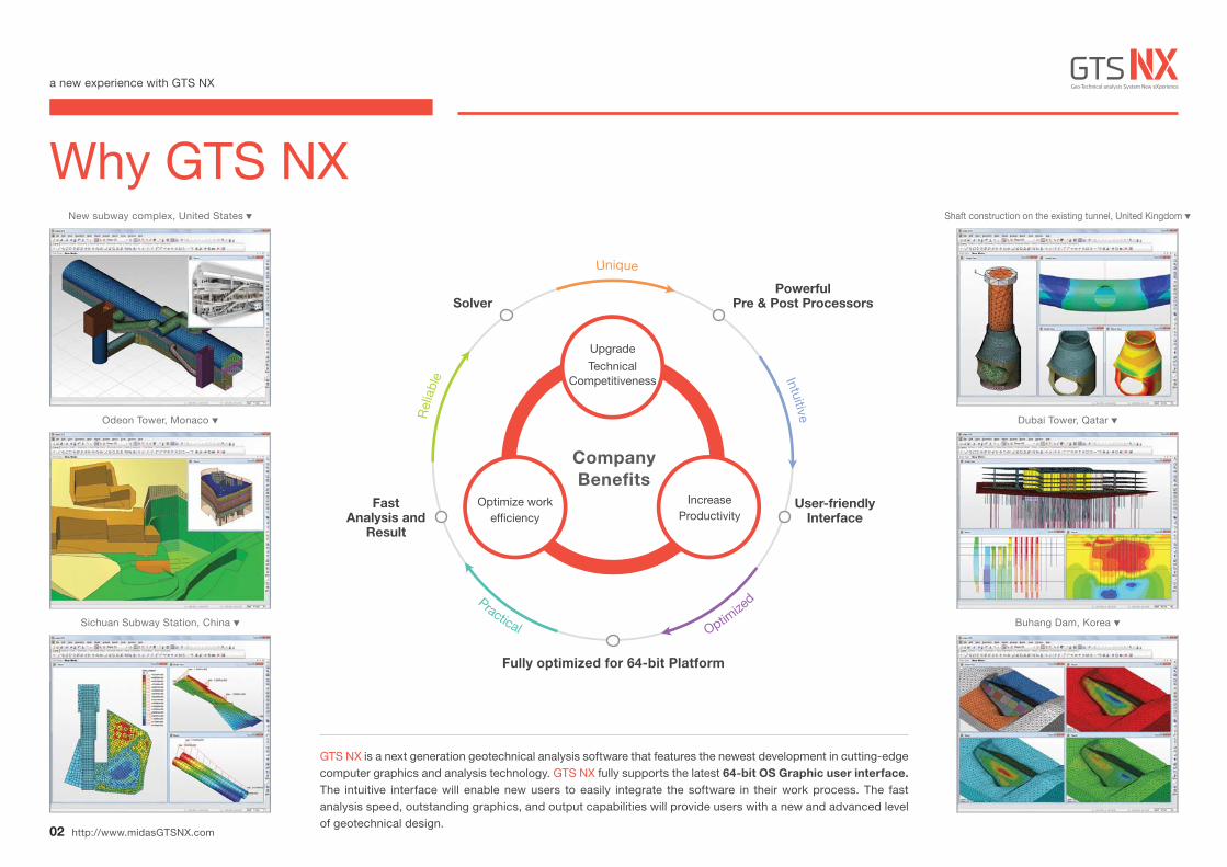
GTS NX is a next generation geotechnical analysis software that features the newest development in cutting-edge computer graphics and analysis technology. GTS NX fully supports the latest 64-bit OS Graphic user interface. The intuitive interface will enable new users to easily integrate the software in their work process. The fast analysis speed, outstanding graphics, and output capabilities will provide users with a new and advanced level of geotechnical design.
http://www.midasGTSNX.com02
Company Benefits
Optimize work efficiency
IncreaseProductivity
Solver
Fast Analysis and
Result
User-friendlyInterface
Powerful Pre & Post Processors
Upgrade
Technical Competitiveness
Fully optimized for 64-bit Platform
Practical Optimize
d
Rel
iabl
e
Unique
Intuitive
a new experience with GTS NX
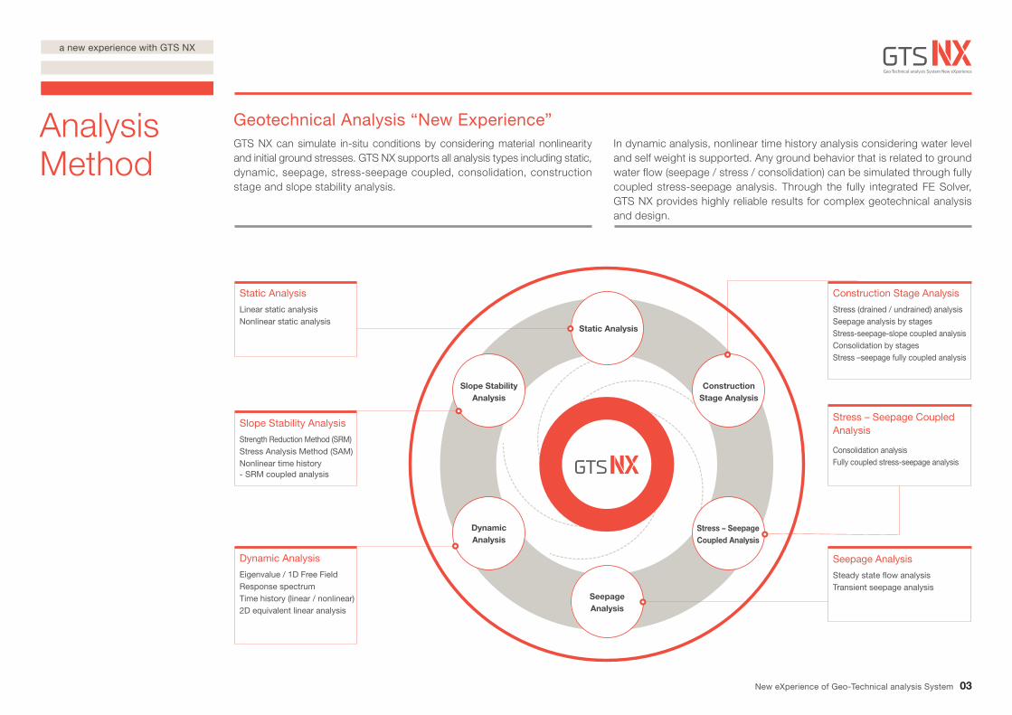
Geotechnical Analysis “New Experience”GTS NX can simulate in-situ conditions by considering material nonlinearity and initial ground stresses. GTS NX supports all analysis types including static, dynamic, seepage, stress-seepage coupled, consolidation, construction stage and slope stability analysis.
In dynamic analysis, nonlinear time history analysis considering water level and self weight is supported. Any ground behavior that is related to ground water flow (seepage / stress / consolidation) can be simulated through fully coupled stress-seepage analysis. Through the fully integrated FE Solver, GTS NX provides highly reliable results for complex geotechnical analysis and design.
Slope Stability Analysis
Construction Stage Analysis
Dynamic Analysis
SeepageAnalysis
Stress – Seepage Coupled Analysis
Dynamic Analysis
Eigenvalue / 1D Free FieldResponse spectrumTime history (linear / nonlinear)2D equivalent linear analysis
Seepage Analysis
Steady state flow analysisTransient seepage analysis
Slope Stability Analysis
Strength Reduction Method (SRM)Stress Analysis Method (SAM)Nonlinear time history - SRM coupled analysis
Stress – Seepage Coupled Analysis
Consolidation analysisFully coupled stress-seepage analysis
Static Analysis
Linear static analysisNonlinear static analysis
03New eXperience of Geo-Technical analysis System
Static Analysis
Analysis Method
Construction Stage Analysis
Stress (drained / undrained) analysisSeepage analysis by stagesStress-seepage-slope coupled analysisConsolidation by stagesStress –seepage fully coupled analysis
a new experience with GTS NX
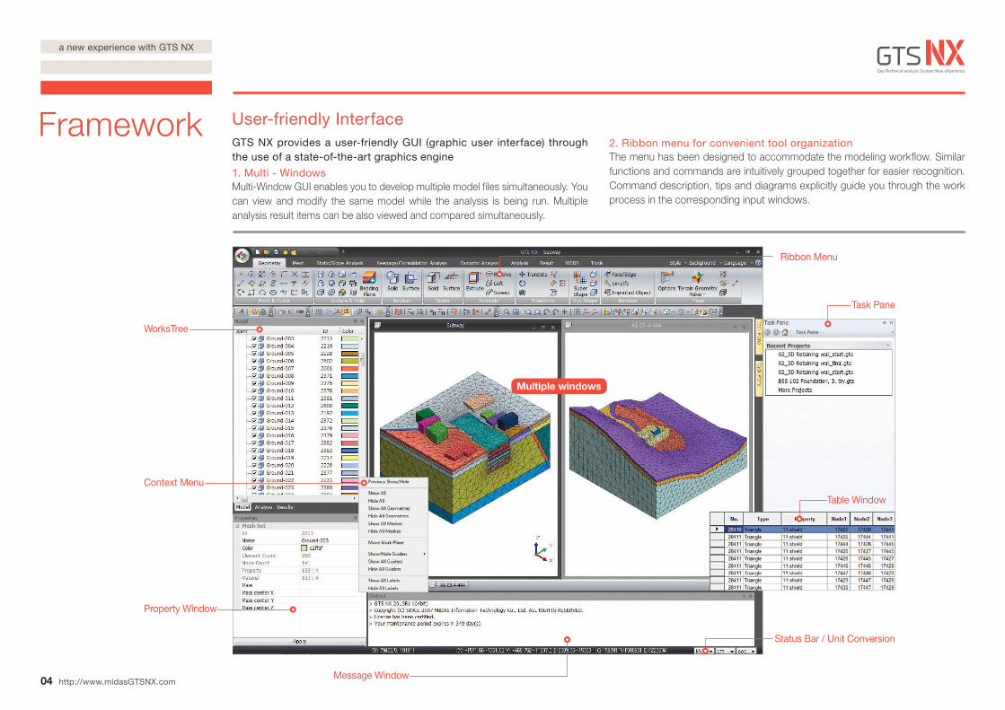
WorksTree
Context Menu
Status Bar / Unit Conversion
Task Pane
Property Window
Message Window
Ribbon Menu
Table Window
Multiple windows
04
Framework User-friendly InterfaceGTS NX provides a user-friendly GUI (graphic user interface) through the use of a state-of-the-art graphics engine
1. Multi - WindowsMulti-Window GUI enables you to develop multiple model files simultaneously. You can view and modify the same model while the analysis is being run. Multiple analysis result items can be also viewed and compared simultaneously.
2. Ribbon menu for convenient tool organizationThe menu has been designed to accommodate the modeling workflow. Similar functions and commands are intuitively grouped together for easier recognition. Command description, tips and diagrams explicitly guide you through the work process in the corresponding input windows.
http://www.midasGTSNX.com
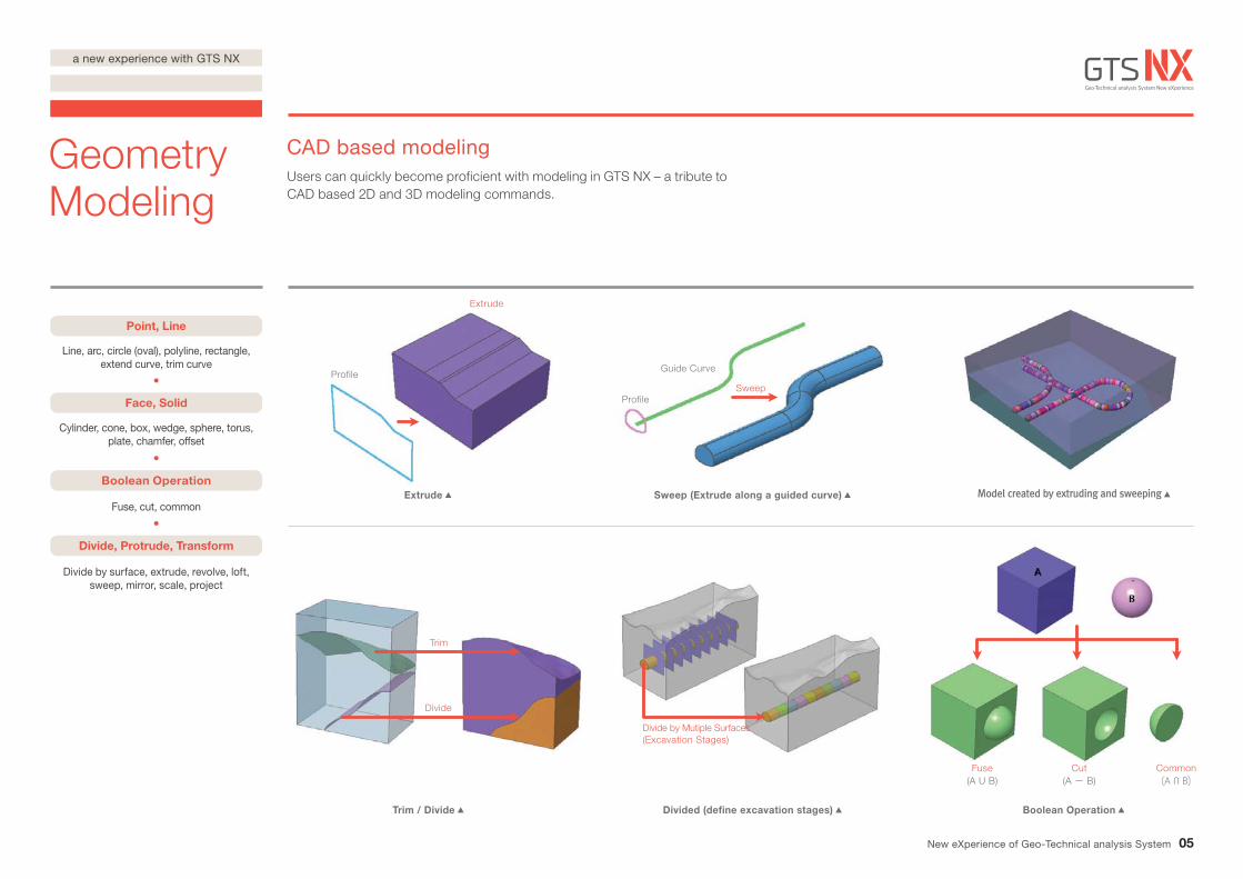
Point, Line
Line, arc, circle (oval), polyline, rectangle, extend curve, trim curve
Face, Solid
Cylinder, cone, box, wedge, sphere, torus, plate, chamfer, offset
Boolean Operation
Fuse, cut, common
Divide, Protrude, Transform
Divide by surface, extrude, revolve, loft, sweep, mirror, scale, project
Profile
Profile
Guide Curve
Extrude
Sweep
Trim / Divide Divided (define excavation stages) Boolean Operation
Extrude Sweep (Extrude along a guided curve)
Trim
Divide
Divide by Mutiple Surfaces(Excavation Stages)
(A U B)Fuse
(A - B)Cut Common
05
Geometry Modeling
CAD based modelingUsers can quickly become proficient with modeling in GTS NX – a tribute to CAD based 2D and 3D modeling commands.
New eXperience of Geo-Technical analysis System
a new experience with GTS NX
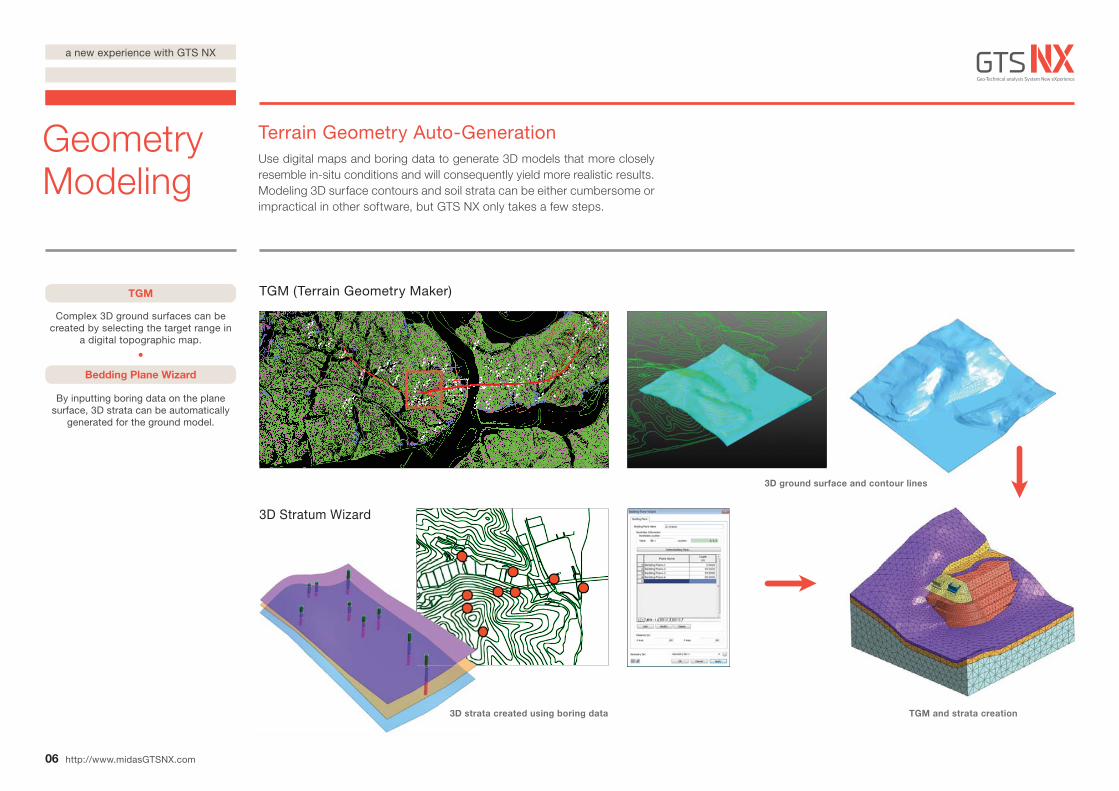
TGM
Complex 3D ground surfaces can be created by selecting the target range in
a digital topographic map.
Bedding Plane Wizard
By inputting boring data on the plane surface, 3D strata can be automatically
generated for the ground model.
3D ground surface and contour lines
3D strata created using boring data TGM and strata creation
TGM (Terrain Geometry Maker)
3D Stratum Wizard
3D strat
06
Geometry Modeling
http://www.midasGTSNX.com
Terrain Geometry Auto-GenerationUse digital maps and boring data to generate 3D models that more closely resemble in-situ conditions and will consequently yield more realistic results. Modeling 3D surface contours and soil strata can be either cumbersome or impractical in other software, but GTS NX only takes a few steps.
a new experience with GTS NX
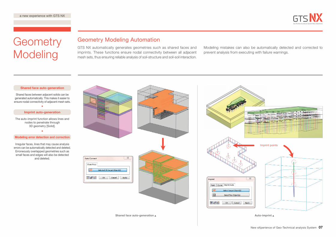
Imprint points
Shared face auto-generation
Shared faces between adjacent solids can be generated automatically. This makes it easier to
ensure nodal connectivity of adjacent mesh sets.
Imprint auto-generation
The auto-imprint function allows lines and nodes to penetrate through
3D geometry [Solid].
Modeling error detection and correction
Irregular faces, lines that may cause analysiserrors can be automatically detected and deleted.Erroneously overlapped geometries such as small faces and edges will also be detected
and deleted.
Shared face auto-generation Auto-imprint
07
Geometry Modeling
Geometry Modeling AutomationGTS NX automatically generates geometries such as shared faces and imprints. These functions ensure nodal connectivity between all adjacent mesh sets, thus ensuring reliable analysis of soil-structure and soil-soil interaction.
Modeling mistakes can also be automatically detected and corrected to prevent analysis from executing with failure warnings.
New eXperience of Geo-Technical analysis System
a new experience with GTS NX
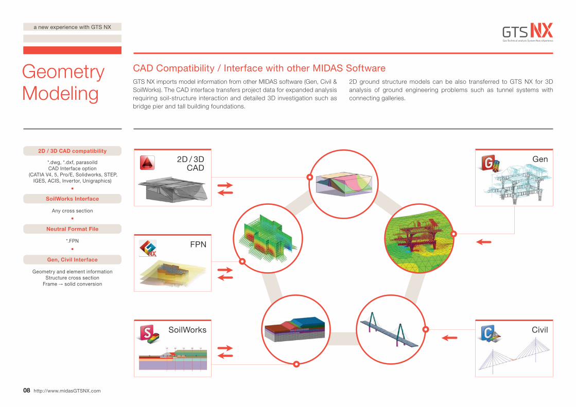
SoilWorks
FPN
Gen
Civil
2D / 3D CAD compatibility
Geometry and element informationStructure cross section
Frame solid conversion
SoilWorks Interface
Neutral Format File
Gen, Civil Interface
Any cross section
*.dwg, *.dxf, parasoildCAD Interface option
(CATIA V4, 5, Pro/E, Solidworks, STEP, IGES, ACIS, Invertor, Unigraphics)
*.FPN
2D / 3D CAD
08
Geometry Modeling
http://www.midasGTSNX.com
CAD Compatibility / Interface with other MIDAS SoftwareGTS NX imports model information from other MIDAS software (Gen, Civil & SoilWorks). The CAD interface transfers project data for expanded analysis requiring soil-structure interaction and detailed 3D investigation such as bridge pier and tall building foundations.
2D ground structure models can be also transferred to GTS NX for 3D analysis of ground engineering problems such as tunnel systems with connecting galleries.
a new experience with GTS NX
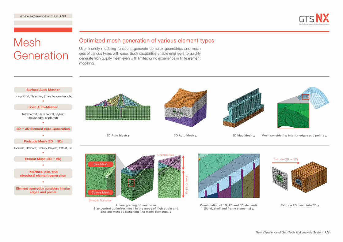
Surface Auto-Mesher
Loop, Grid, Delaunay (triangle, quadrangle)
Solid Auto-Mesher
Tetrahedral, Hexahedral, Hybrid (hexahedral centered)
Protrude Mesh (2D 3D)
Extrude, Revolve, Sweep, Project, Offset, Fill
2D 3D Element Auto-Generation
Extract Mesh (3D 2D)
Interface, pile, and structural element generation
Element generation considers interior edges and points
2D Auto Mesh
Linear grading of mesh sizeSize control optimizes mesh in the areas of high strain and
displacement by assigning fine mesh elements.
3D Map Mesh Mesh considering interior edges and points
Extrude 2D mesh into 3DCombination of 1D, 2D and 3D elements(Solid, shell and frame elements)
3D Auto Mesh
Extrude (2D 3D)
Fine Mesh
Coarse Mesh
Smooth Transition
Uniform SizeLinear G
rading
09
Mesh Generation
Optimized mesh generation of various element typesUser friendly modeling functions generate complex geometries and mesh sets of various types with ease. Such capabilities enable engineers to quickly generate high quality mesh even with limited or no experience in finite element modeling.
New eXperience of Geo-Technical analysis System
a new experience with GTS NX
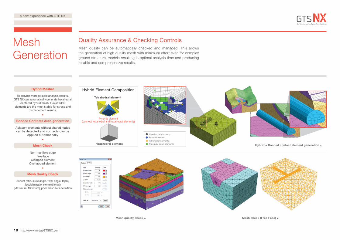
Hybrid Mesher
To provide more reliable analysis results, GTS NX can automatically generate hexahedral
centered hybrid mesh. Hexahedral elements are the most stable for stress and
displacement results.
Bonded Contacts Auto-generation
Mesh Check
Mesh Quality Check
Adjacent elements without shared nodes can be detected and contacts can be
applied automatically
Non-manifold edgeFree face
Clamped elementOverlapped element
Aspect ratio, skew angle, twist angle, taper, Jacobian ratio, element length
(Maximum, Minimum), poor mesh sets definition
Mesh quality check Mesh check (Free Face)
Hybrid + Bonded contact element generation
Hybrid Element Composition
Pyramid element (connect tetrahedral and hexahedral elements)
Tetrahedral element
10
Mesh Generation
http://www.midasGTSNX.com
Quality Assurance & Checking ControlsMesh quality can be automatically checked and managed. This allows the generation of high quality mesh with minimum effort even for complex ground structural models resulting in optimal analysis time and producing reliable and comprehensive results.
Hexahedral elementsPyramid element Tetrahedral elements Triangular prism elementsHexahedral element
a new experience with GTS NX
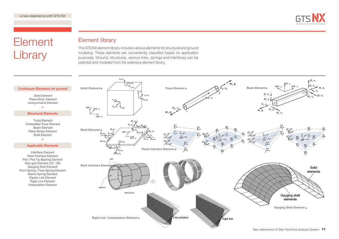
Shell Interface Element
Truss Element Embedded Truss Element
Beam ElementPlane Stress Element
Shell Element
Interface ElementShell Interface Element
Pile / Pile Tip Bearing ElementGeo-grid Element (1D / 2D)
Gauging Shell ElementPoint Spring / Face Spring Element
Matrix Spring ElementElastic Link ElementRigid Link Element
Interpolation Element
Rigid Link / Interpolation Element
Continuum Elements for ground
Solid Element Plane Strain Element
Axisymmetric Element
Structural Elements
Applicable Elements
Solid Element Truss Element Beam Element
Shell Element
Plane Interface Element
Gauging Shell Element
11
ElementLibrary
Element libraryThe GTS NX element library includes various elements for structural and ground modeling. These elements are conveniently classified based on application purposes. Ground, structures, various links, springs and interfaces can be selected and modeled from the extensive element library.
New eXperience of Geo-Technical analysis System
a new experience with GTS NX
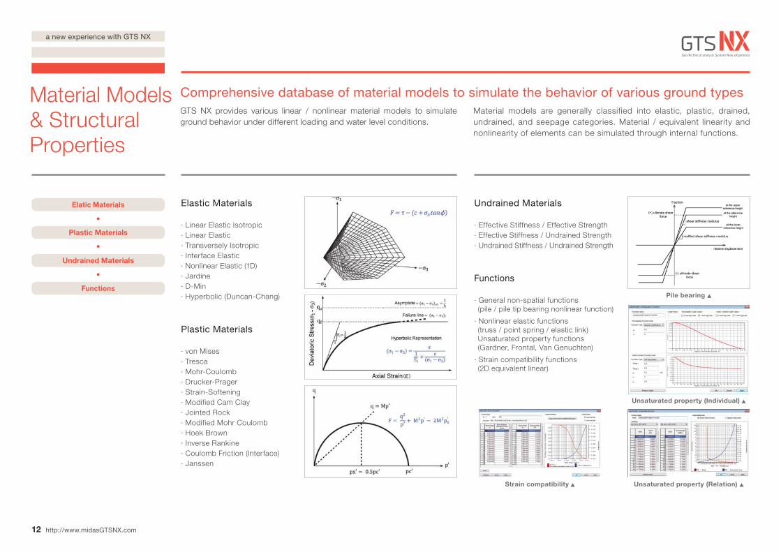
Elastic Materials
· Linear Elastic Isotropic· Linear Elastic· Transversely Isotropic· Interface Elastic· Nonlinear Elastic (1D)· Jardine· D-Min· Hyperbolic (Duncan-Chang)
Plastic Materials
· von Mises· Tresca · Mohr-Coulomb· Drucker-Prager· Strain-Softening· Modified Cam Clay· Jointed Rock· Modified Mohr Coulomb· Hoek Brown· Inverse Rankine· Coulomb Friction (Interface)· Janssen
Undrained Materials
· Effective Stiffness / Effective Strength· Effective Stiffness / Undrained Strength· Undrained Stiffness / Undrained Strength
Functions
· General non-spatial functions (pile / pile tip bearing nonlinear function)
· Nonlinear elastic functions (truss / point spring / elastic link) Unsaturated property functions (Gardner, Frontal, Van Genuchten)
· Strain compatibility functions (2D equivalent linear)
Strain compatibility
Pile bearing
Unsaturated property (Individual)
Unsaturated property (Relation)
Elatic Materials
Plastic Materials
Undrained Materials
Functions
12
Material Models & Structural Properties
http://www.midasGTSNX.com
Comprehensive database of material models to simulate the behavior of various ground typesGTS NX provides various linear / nonlinear material models to simulate ground behavior under different loading and water level conditions.
Material models are generally classified into elastic, plastic, drained, undrained, and seepage categories. Material / equivalent linearity and nonlinearity of elements can be simulated through internal functions.
a new experience with GTS NX
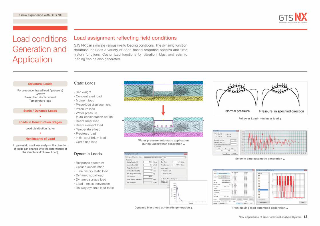
Static Loads
· Self weight· Concentrated load· Moment load· Prescribed displacement· Pressure load· Water pressure (auto-consideration option)· Beam linear load· Beam element load· Temperature load· Prestress load· Initial equilibrium load· Combined load
Dynamic Loads
· Response spectrum· Ground acceleration· Time history static load· Dynamic nodal load· Dynamic surface load· Load – mass conversion· Railway dynamic load table
Seismic data automatic generation
Dynamic blast load automatic generation Train moving load automatic generation
Water pressure automatic application during underwater excavation
Follower Load- nonlinear load
Structural Loads
Force (concentrated load / pressure)Gravity
Prescribed displacementTemperature load
Static / Dynamic Loads
Loads in Construction Stages
Load distribution factor
Nonlinearity of Load
In geometric nonlinear analysis, the direction of loads can change with the deformation of
the structure. (Follower Load)
13
Load conditionsGeneration and Application
Load assignment reflecting field conditionsGTS NX can simulate various in-situ loading conditions. The dynamic function database includes a variety of code-based response spectra and time history functions. Customized functions for vibration, blast and seismic loading can be also generated.
New eXperience of Geo-Technical analysis System
a new experience with GTS NX
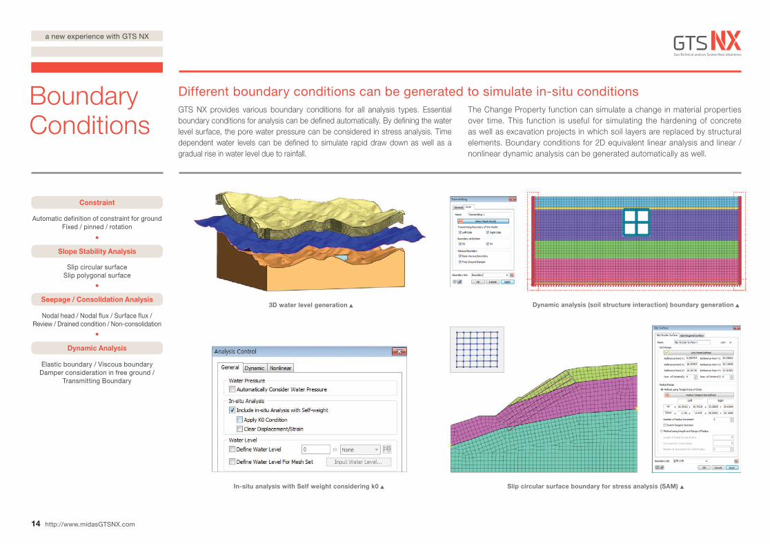
Dynamic analysis (soil structure interaction) boundary generation3D water level generation
Slip circular surface boundary for stress analysis (SAM) In-situ analysis with Self weight considering k0
Constraint
Automatic definition of constraint for groundFixed / pinned / rotation
Slope Stability Analysis
Seepage / Consolidation Analysis
Dynamic Analysis
Slip circular surface Slip polygonal surface
Nodal head / Nodal flux / Surface flux / Review / Drained condition / Non-consolidation
Elastic boundary / Viscous boundary Damper consideration in free ground /
Transmitting Boundary
14
Boundary Conditions
http://www.midasGTSNX.com
Different boundary conditions can be generated to simulate in-situ conditions GTS NX provides various boundary conditions for all analysis types. Essential boundary conditions for analysis can be defined automatically. By defining the water level surface, the pore water pressure can be considered in stress analysis. Time dependent water levels can be defined to simulate rapid draw down as well as a gradual rise in water level due to rainfall.
The Change Property function can simulate a change in material properties over time. This function is useful for simulating the hardening of concrete as well as excavation projects in which soil layers are replaced by structural elements. Boundary conditions for 2D equivalent linear analysis and linear / nonlinear dynamic analysis can be generated automatically as well.
a new experience with GTS NX
Contour – Continuous / Fringe
Vector, Diagram
Deformed / Undeformed
Multi-Step Iso Surface
Iso Value Surface
Flow Net
Failure Surface of Slope
Time History Graph
Real-Time Animation
3D 2D Result Wizard
Extract results on any 2D cross section from 3D results without extra calculation
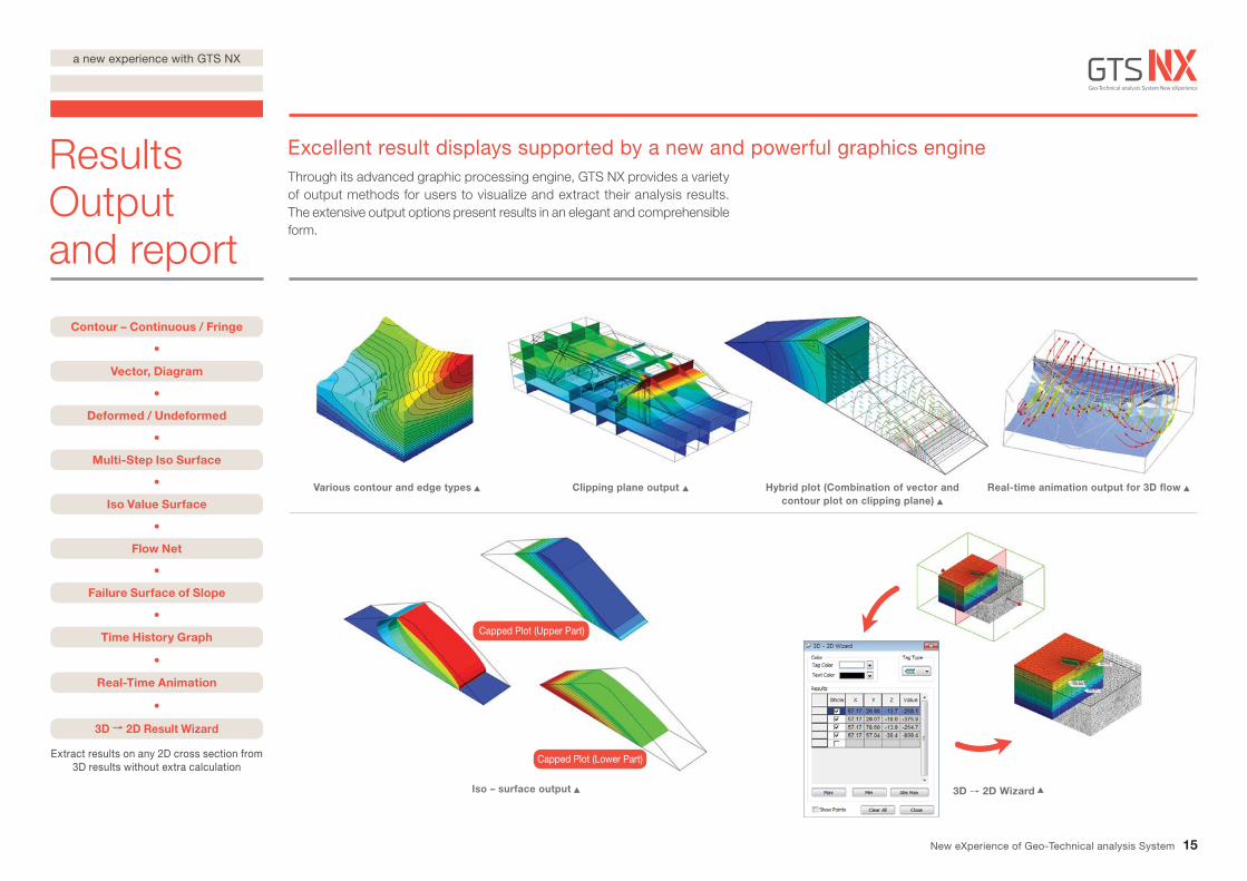
Various contour and edge types Clipping plane output Hybrid plot (Combination of vector and contour plot on clipping plane)
Real-time animation output for 3D flow
Iso – surface output
Capped Plot (Upper Part)
Capped Plot (Lower Part)
3D 2D Wizard
15
Results Output and report
Excellent result displays supported by a new and powerful graphics engineThrough its advanced graphic processing engine, GTS NX provides a variety of output methods for users to visualize and extract their analysis results. The extensive output options present results in an elegant and comprehensible form.
New eXperience of Geo-Technical analysis System
a new experience with GTS NX
Cutting Diagram on any line and plane
Extract Result / Probe Result
3D PDF Output
Graph / Table / Result Image Automatic save
Text File Results Output
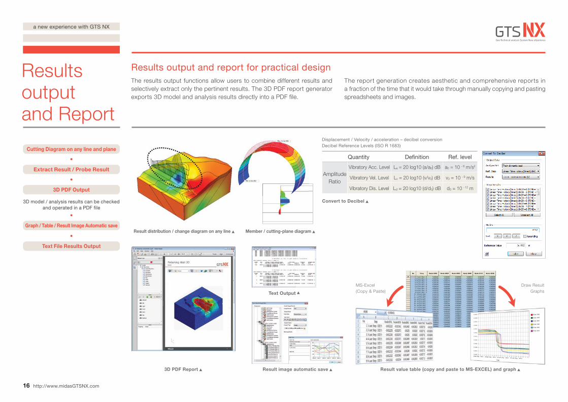
Result distribution / change diagram on any line
3D PDF Report Result image automatic save
Text Output
Convert to Decibel
Result value table (copy and paste to MS-EXCEL) and graph
Draw Result Graphs
MS-Excel (Copy & Paste)
3D model / analysis results can be checkedand operated in a PDF file
Displacement / Velocity / acceleration – decibel conversion
16
Results output and Report
http://www.midasGTSNX.com
Results output and report for practical designThe results output functions allow users to combine different results and selectively extract only the pertinent results. The 3D PDF report generator exports 3D model and analysis results directly into a PDF file.
The report generation creates aesthetic and comprehensive reports in a fraction of the time that it would take through manually copying and pasting spreadsheets and images.
Quantity Definition Ref. level
AmplitudeRatio
Vibratory Acc. Level La = 20 log10 (a/a0) dB a0 = 10 - 6 m/s2
Vibratory Vel. Level Lv = 20 log10 (v/v0) dB v0 = 10 - 9 m/s
Vibratory Dis. Level Ld = 20 log10 (d/d0) dB d0 = 10 - 12 m
Decibel Reference Levels (ISO R 1683)
Member / cutting-plane diagram
a new experience with GTS NX
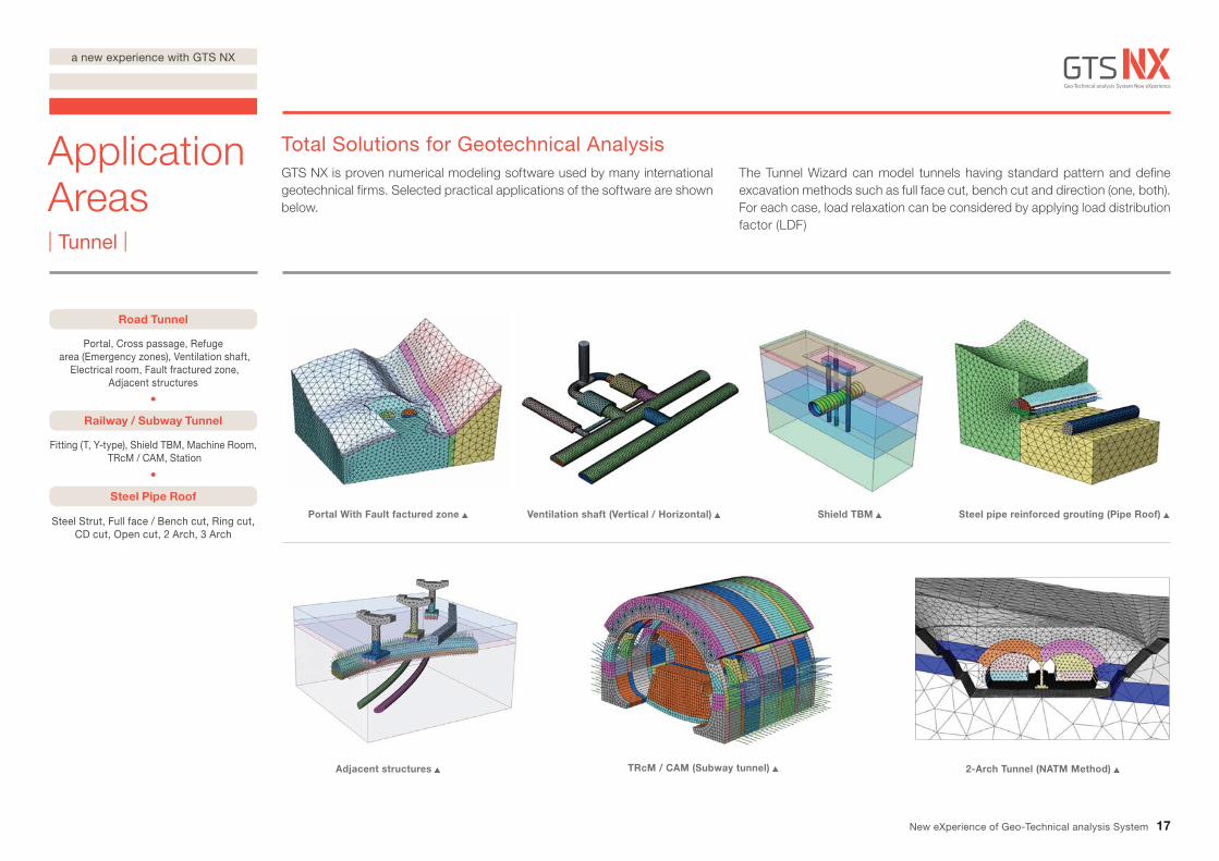
Road Tunnel
Portal, Cross passage, Refuge area (Emergency zones), Ventilation shaft,
Electrical room, Fault fractured zone, Adjacent structures
Steel Pipe Roof
Railway / Subway Tunnel
Fitting (T, Y-type), Shield TBM, Machine Room, TRcM / CAM, Station
Steel Strut, Full face / Bench cut, Ring cut, CD cut, Open cut, 2 Arch, 3 Arch
Portal With Fault factured zone
Adjacent structures
Ventilation shaft (Vertical / Horizontal)
TRcM / CAM (Subway tunnel)
Shield TBM Steel pipe reinforced grouting (Pipe Roof)
2-Arch Tunnel (NATM Method)
17
Application Areas| Tunnel |
Total Solutions for Geotechnical AnalysisGTS NX is proven numerical modeling software used by many international geotechnical firms. Selected practical applications of the software are shown below.
The Tunnel Wizard can model tunnels having standard pattern and define excavation methods such as full face cut, bench cut and direction (one, both). For each case, load relaxation can be considered by applying load distribution factor (LDF)
New eXperience of Geo-Technical analysis System
a new experience with GTS NX
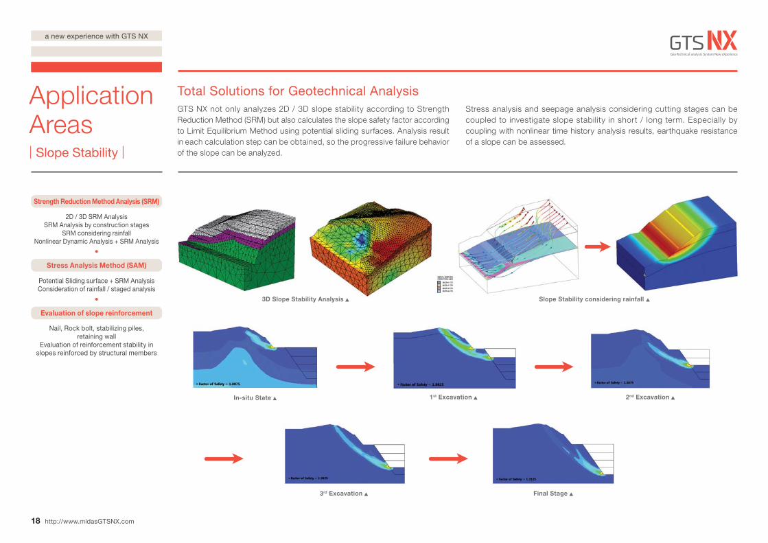
Slope Stability considering rainfall 3D Slope Stability Analysis
In-situ State 1st Excavation 2nd Excavation
3rd Excavation Final Stage
Strength Reduction Method Analysis (SRM)
2D / 3D SRM AnalysisSRM Analysis by construction stages
SRM considering rainfallNonlinear Dynamic Analysis + SRM Analysis
Stress Analysis Method (SAM)
Evaluation of slope reinforcement
Potential Sliding surface + SRM AnalysisConsideration of rainfall / staged analysis
Nail, Rock bolt, stabilizing piles, retaining wall
Evaluation of reinforcement stability in slopes reinforced by structural members
18
Application Areas| Slope Stability |
http://www.midasGTSNX.com
Total Solutions for Geotechnical AnalysisGTS NX not only analyzes 2D / 3D slope stability according to Strength Reduction Method (SRM) but also calculates the slope safety factor according to Limit Equilibrium Method using potential sliding surfaces. Analysis result in each calculation step can be obtained, so the progressive failure behavior of the slope can be analyzed.
Stress analysis and seepage analysis considering cutting stages can be coupled to investigate slope stability in short / long term. Especially by coupling with nonlinear time history analysis results, earthquake resistance of a slope can be assessed.
a new experience with GTS NX
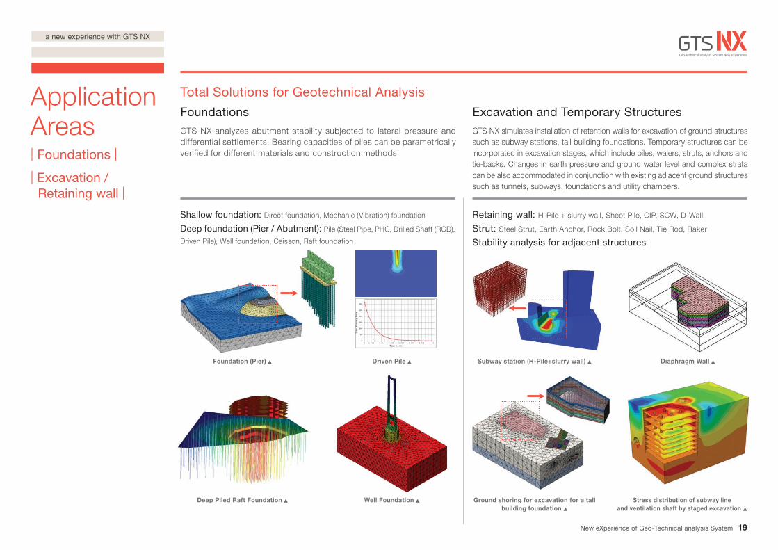
Deep Piled Raft Foundation Well Foundation
Foundation (Pier) Driven Pile Subway station (H-Pile+slurry wall) Diaphragm Wall
Ground shoring for excavation for a tall building foundation
Stress distribution of subway lineand ventilation shaft by staged excavation
19
Application Areas| Foundations |
| Excavation / Retaining wall |
Total Solutions for Geotechnical Analysis
Foundations GTS NX analyzes abutment stability subjected to lateral pressure and differential settlements. Bearing capacities of piles can be parametrically verified for different materials and construction methods.
Excavation and Temporary Structures GTS NX simulates installation of retention walls for excavation of ground structures such as subway stations, tall building foundations. Temporary structures can be incorporated in excavation stages, which include piles, walers, struts, anchors and tie-backs. Changes in earth pressure and ground water level and complex strata can be also accommodated in conjunction with existing adjacent ground structures such as tunnels, subways, foundations and utility chambers.
Shallow foundation: Direct foundation, Mechanic (Vibration) foundation
Deep foundation (Pier / Abutment): Pile (Steel Pipe, PHC, Drilled Shaft (RCD),
Driven Pile), Well foundation, Caisson, Raft foundation
Retaining wall: H-Pile + slurry wall, Sheet Pile, CIP, SCW, D-Wall
Strut: Steel Strut, Earth Anchor, Rock Bolt, Soil Nail, Tie Rod, Raker
Stability analysis for adjacent structures
New eXperience of Geo-Technical analysis System
a new experience with GTS NX
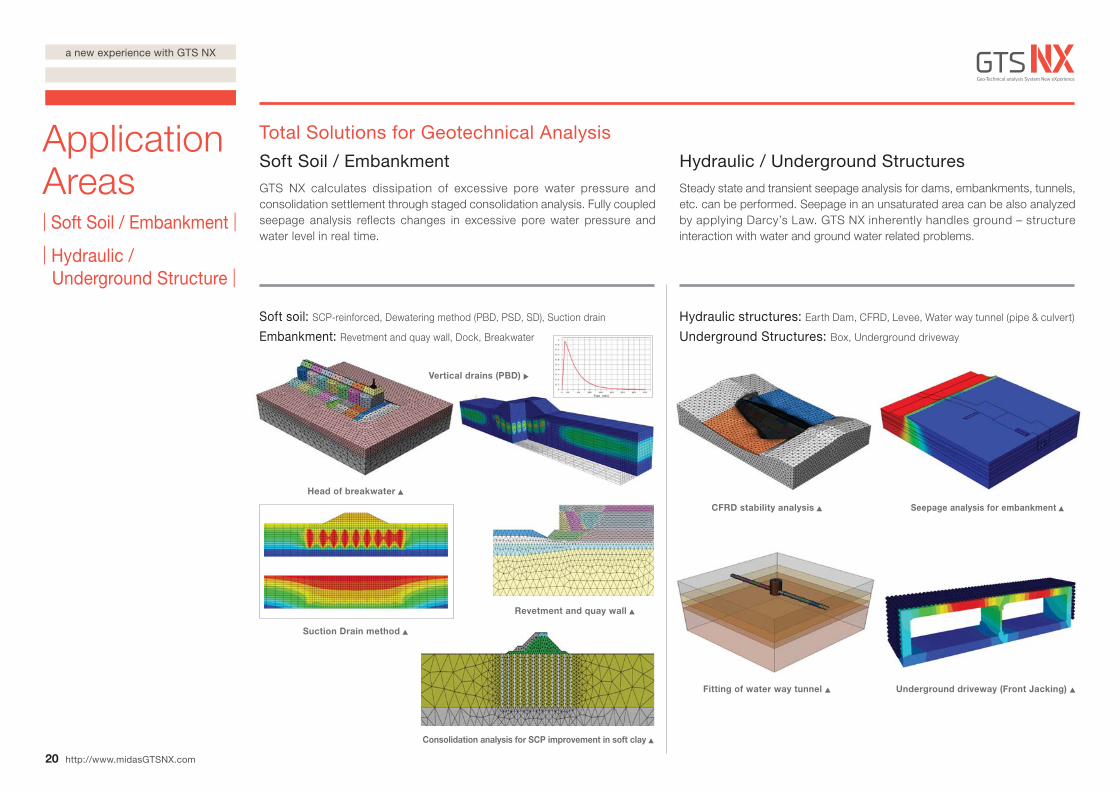
Soft soil: SCP-reinforced, Dewatering method (PBD, PSD, SD), Suction drain
Embankment: Revetment and quay wall, Dock, Breakwater
Hydraulic structures: Earth Dam, CFRD, Levee, Water way tunnel (pipe & culvert)
Underground Structures: Box, Underground driveway
Fitting of water way tunnel
CFRD stability analysis
Underground driveway (Front Jacking)
Seepage analysis for embankment
Consolidation analysis for SCP improvement in soft clay
Head of breakwater
Suction Drain method
Revetment and quay wall
Vertical drains (PBD)
20
Application Areas| Soft Soil / Embankment |
| Hydraulic / Underground Structure |
http://www.midasGTSNX.com
Total Solutions for Geotechnical Analysis
Soft Soil / Embankment GTS NX calculates dissipation of excessive pore water pressure and consolidation settlement through staged consolidation analysis. Fully coupled seepage analysis reflects changes in excessive pore water pressure and water level in real time.
Hydraulic / Underground Structures Steady state and transient seepage analysis for dams, embankments, tunnels, etc. can be performed. Seepage in an unsaturated area can be also analyzed by applying Darcy’s Law. GTS NX inherently handles ground – structure interaction with water and ground water related problems.
a new experience with GTS NX
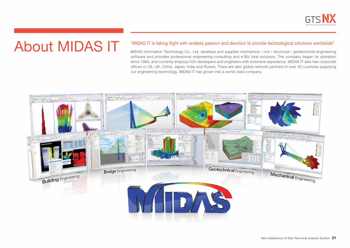
About MIDAS IT MIDAS Information Technology Co., Ltd. develops and supplies mechanical / civil / structural / geotechnical engineering software and provides professional engineering consulting and e-Biz total solutions. The company began its operation since 1989, and currently employs 530 developers and engineers with extensive experience. MIDAS IT also has corporate offices in US, UK, China, Japan, India and Russia. There are also global network partners in over 30 countries supplying our engineering technology. MIDAS IT has grown into a world class company.
“MIDAS IT is taking flight with endless passion and devotion to provide technological solutions worldwide”
21New eXperience of Geo-Technical analysis System
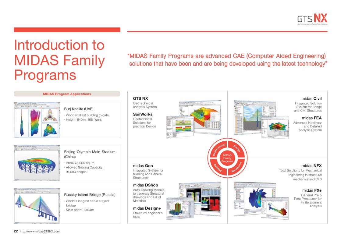
Introduction to MIDAS Family Programs
“MIDAS Family Programs are advanced CAE (Computer Aided Engineering) solutions that have been and are being developed using the latest technology”
MIDAS Program Applications
Burj Khalifa (UAE)
· World’s tallest building to date· Height: 840m, 168 floors
Beijing Olympic Main Stadium (China)
· Area: 78,000 sq. m.· Allowed Seating Capacity: 91,000 people
Russky Island Bridge (Russia)
· World’s longest cable stayed bridge· Main span: 1,104m
GTS NXGeoTechnical analysis System
SoilWorksGeotechnical Solutions for practical Design
midas GenIntegrated System for building and General Structures
midas DShopAuto-Drawing Module to generate Structural drawings and Bill of Materials
midas Design+Structural engineer’s tools
midas NFXTotal Solutions for Mechanical
Engineering in structural mechanics and CFD
midas FX+General Pre &
Post Processor for Finite Element
Analysis
midas CivilIntegrated Solution System for Bridge
and Civil Structures
midas FEAAdvanced Nonlinear
and Detailed Analysis System
MIDASFamily
Programs
Geo
te
chnical Bridge
Mechanica
l
Building
22 http://www.midasGTSNX.com

Integrated Solver Optimized for the next generation 64 - bit platform
Finite Element Solutions for Geotechnical Engineering
Copyright © Since 1989 MIDAS Information Technology Co., Ltd. All rights reserved.www.MidasUser.com http://www.midasGTSNX.com


