45
Omnibot 2000 IMDL: Summer 1999 by Scott Nortman

Omnibot 2000
IMDL: Summer 1999
by
Scott Nortman

Integrated System
Omnibot 2000 is an autonomous mobile agent (robot) built for the Intelligent
Machines Design Laboratory during the summer of 1999. The robot resembles the upper
torso of a human. It has two arms and a head, and sits on a mobile base. Each arm has
five degrees of freedom, including a gripper as an end effector. The robot also has two
degrees of freedom for the head, allowing it to pan and tilt. Additionally, the base
contains six drive wheels. The robot has a total of 12 degrees of freedom; each actuated
by a servo. The wheeled base also has two drive motors, each rotating a pair of wheels on
each side of the robot.
The robot also contains three Motorola 68HC11 microcontrollers. One is
operating in single chip mode on a Mekatronix MSCC11 circuit board. The other two are
operating in expanded multiplexed mode with 32K of SRAM. One is on a Mekatronix TJ
Pro circuit board and the other is on a Motorola EVBU board. The robot also has a voice
synthesizer module, voice recognition, low-resolution vision, 12 infrared emitters and
detectors, and four bump sensors.
The robot was designed to aid the elderly, the disabled, or those who are in need
of assistance. It can perform simple functions, such as grabbing or carrying small
objects. The operator issues commands to the robot, and the robot then responds by
performing the requested task. The functions are low level, such as, “Gripper left plus
[amount]” or, “Body forward.” In addition to this “slave” behavior, the robot can
entertain audiences by singing and dancing to YMCA. The robot also introduces itself

and explains many of its features. Finally, the robot was also programmed to give my
oral presentation.
The block diagram of the robot is shown in Figure 1. The 68HC11 on the EVBU
board execute the main program, and takes in data from the sensors. It also sends
commands to the MSCC11 via the SCI port to control the servos.
The structure of the robot was designed with the end user in mind. People who
may need assistance will find that the robot is easy to use. The robot resembles a human;
there are two arms and a head, so there are similarities between the way a person move
and the way the robot moves. Therefore, when assistance is required, the user intuitively
knows how to instruct the robot to move.
FIGURE 1:
68HC11
EVBU/ME11
68HC11
TJ PRO
DRIVEMOTORS
VIOCESYNTHSIZER
VOICERECOGNITION
LeftCdS
Array
RightCds
Array
SONAR
SERVO
SERVO
SERVO
SERVO
SERVO
SERVO
SERVO
SERVO
SERVO
SERVO
SERVO
SERVO
68HC11
MSCC11

Mobile Platform
The platform is a Tomy Omnibot 2000, a robotic toy manufactured in the early
1980’s. It is 30 inches tall, 24 inches wide and 15 inches deep. It has a head with two
eye sockets, two arms with grippers, and sits on a wheeled base. It originally contained
control electronics, a cassette tape player, a liquid crystal display, and small DC motors
for actuation of some of the joints. I removed all of the stock electronics, except for the
two drive motors.
Although the robot was designed as a child’s toy, many improvements were made
to the mechanical structure. First, seven more degrees of freedom were added, and the
five existing ones were modified. Each arm has five, including the pitch and yaw of the
shoulder, the pitch of the elbow, the rotation of the wrist, and the opening and closing of
the gripper. The head can also pan and tilt. Therefore, the robot now has 12 degrees of
freedom.
The entire platform is mobile. There are two drive motors in the base, each
rotating two drive wheels. There are also two more wheels that are not motorized for
added stability. The configuration is shown in Figure 2:

FIGURE 2:
Top View
IR Emitter/Detectors
MOTORIZEDWHEELS
FRONT

Actuation and Output Devices
The goal of Omnibot 2000 is to help and entertain people. Help is provided by
means of the robotic arms; they can grasp objects, move the objects to a new location and
then release the objects. For example, the arms can grab a can of soda, then lift the can,
rotate the wrist to pour the soda into a glass, and then return the can to its original
position. As for entertainment, the robot uses the arms to form the letters “Y”, “M”, “C”,
and “A” while singing and dancing to YMCA.
The original robot had small DC motors in the right arm providing movement to
the shoulder pitch, the rotation of the wrist, and the actuation of the gripper. However,
these motors did not have enough torque for the desired application. Seven more degrees
of freedom were added, and the same control algorithms were needed for all of the joints.
Therefore, the motors that came with the robot were removed and replaced by servos.
To accomplish the specified goals, Omnibot 2000 needed servos that can supply
enough torque to move all of the joints. The servo torque must also provide strength for
the arms to lift objects in the grippers. The grippers also need high torque servos to grasp
objects without slipping. Due to these requirements, Omnibot 2000 uses precision Cirrus
Hobbies servos.
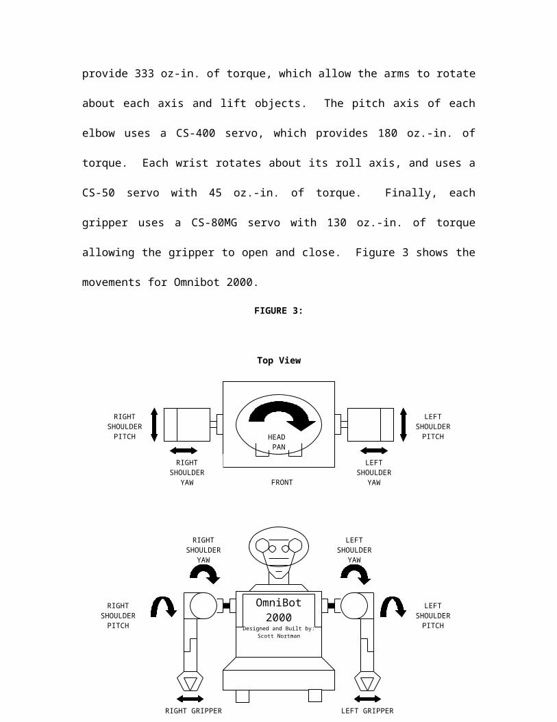
The shoulder joints have two degrees of freedom along the pitch axis and yaw
axis. They may be moved independently, each using a CS-600 servo. The servos
provide 333 oz-in. of torque, which allow the arms to rotate about each axis and lift
objects. The pitch axis of each elbow uses a CS-400 servo, which provides 180 oz.-in. of
torque. Each wrist rotates about its roll axis, and uses a CS-50 servo with 45 oz.-in. of

torque. Finally, each gripper uses a CS-80MG servo with 130 oz.-in. of torque allowing
the gripper to open and close. Figure 3 shows the movements for Omnibot 2000.
FIGURE 3:
Top View
Front View:
HEAD PAN
RIGHT SHOULDER
YAW
LEFT SHOULDER
YAWFRONT
LEFTSHOULDER
PITCH
RIGHTSHOULDER
PITCH
OmniBot2000
Designed and Built by:Scott Nortman
LEFT GRIPPERRIGHT GRIPPER
LEFT SHOULDER
PITCH
RIGHT SHOULDER
PITCH
LEFT SHOULDER
YAW
RIGHT SHOULDER
YAW

Left View:
The servos are controlled by a Motorola 68HC11 microcontroller on a
Mekatronix MSCC11 circuit board, operating in single chip mode. This microcontroller
generates the pulse width modulation (PWM) signals needed by the servos. The signal is
a TTL level pulse, with a period of 20 milliseconds. The duty cycle varies between zero
and ten percent. A zero percent duty cycle causes the servo to position the output shaft at
zero degrees, while a ten percent duty cycle positions the output shaft at 180 degrees.
The single chip microcontroller receives data from another 68HC11
microcontroller through the asynchronous serial port (SCI). The transferred data frame
contains three bytes for each action performed by the servo. The first byte is a zero,
indicating the beginning of a frame. The second byte contains a number between zero
HEAD TILT
LEFT SHOULDER PITCH
LEFT ELBOW PITCH
and 15, determining which servo should be moved. The third and final byte of the frame
is a number from zero to 128, indicating the position the selected servo should move to.
The code may be found in the appendix.
Although the above method of control is easy to implement, there are some
disadvantages to using the SCI port. First, because the frame of data is transferred with
the SCI port, a terminal may not be used to troubleshoot the robot during debugging or
during use. Second, when any code is downloaded to the main microcontroller, the SCI
lines must be disconnected from the main microcontroller because the data will also be
transferred to the single chip controller, causing the servos to move to undesired
positions. An alternate to disconnecting the SCI lines is to add a separate power switch
to the single chip microcontroller so the PWM signals can not be generated.
For Omnibot 2000 to move around, drive motors are used. The base contains two
drive motors from the original design. They are housed in a gearbox in between the sets
of wheels. The motors are gear-reduced to increase their output torque and reduce their
speed. There is a transmission feature in the gearbox, allowing the output of the gearbox
to have a “high speed” and a “low speed” selection. This feature was not used for the
current design, and the transmission was left in the “high speed” position. The drive
motors and gearbox do have some limitations. They were not designed to carry the
weight of the modified Omnibot 2000 robot. Because of the added weight, they are slow,
loud, and do not allow the robot to turn well.
The stall current of the motors was determined experimentally, as shown in
Figure 4. The stall current was found to average 1.27 Amps. The low current
requirements of the drive motors permitted the use of a single chip motor driver. The

chip is a Texas Instruments L293D Quadruple Half H Driver. The chip can provide
enough current, however a heat sink was needed because the chip is designed to handle
1200 mA per coil and the stall current is 1270 mA for each coil.
The control signals are provided by another Motorola 68HC11 microcontroller,
operating in expanded multiplexed mode. This controller is on an EVBU board, with a
Mekatronix ME11 daughter board containing 32k of SRAM, a 74HC390 clock divider
chip, and a memory mapped output port. Each of the drive motors requires two control
signals from the microcontroller, the first for direction and the second for speed. The
direction control lines used are port D bits 4 and 5. The speed control lines are from port,
bits 5 and 6.
FIGURE 4:
LEFT DRIVE MOTOR
RIGHT DRIVE
MOTOR
V V
3.16 OhmRESISTORS
VCC VCC
Sensors
Onmibot 2000 has four different sensor suites. The first uses eight infrared (IR)
emitters and detectors, arranged around the base, to determine the proximity of objects
from the base. The second suite consists of four bump sensors. Two of the bump sensors
are in the front of the base, and the other two are in the back. Next is the “special”
sensor: voice recognition. This sensor is actually located in a separate, wearable module.
The final sensor is low-resolution vision. However, due to time constraints, this last
system is not functioning.
There are 12 IR emitter/ detector pairs are arranged around the bottom of the base
as shown in Figure 2. Although there are 12 emitters and detectors, the center pairs on
each side are not connected, and only eight are currently in use. They emit IR light
modulated at 40kHz. The emitters are connected to a memory mapped output latch.
Writing a 1 to the corresponding bit at address 0x7000 turns them on. The detectors are
modified Sharp GP1U58Y IR sensors. They have been modified so they output an
analog voltage in response to detected IR light. Therefore, the returned voltage is in
proportion to the proximity of objects. The eight detectors are connected to port E of the
68HC11 operating in expanded multiplexed mode. Port E connects them to the internal
analog to digital (AD) converter. Hopefully the IR sensors will prevent the robot from
contacting any objects. However, if the robot does hit an object, the bump sensor will
indicate a collision. The robot will then say, “Ouch!” and either back up or turn away or
speed up, depending on which bump sensor(s) was contacted. If both front and back
sensors are pressed at the same time, the robot will shut off the motors to prevent the
motor driver from overheating.

The “special” sensor is voice recognition. Voice recognition was chosen
because speech is a natural way to communicate. Software that performs speech
recognition is currently available for personal computers. These programs operate
simultaneously with the computer operating system. However, the disadvantages include
the requirement of a compatible sound card, and the necessity of a computer. While these
speech programs are impressive, they can not be inexpensively incorporated into an
autonomous mobile robot. Fortunately, another option is available.
Another more viable voice sensor approach is with hardware that does not require
a computer. The use of this sensor on an autonomous mobile robot is made possible by
an HM2007 IC chip. The chip provides the options of recognizing either 40 words .96
second long or 20 words 1.92 seconds long. The circuit I am using selects the .96 second
word length enabling the chip to recognize 40 independent words.
Although only 40 words may be recognized, these words control all of the functions of
my robot. The words that may be understood are shown in Figure 5. The words may be
used to change behaviors. Accordingly, if I say, “Slave,” the robot will stop its current
behavior and respond to my spoken commands only, as opposed to its other sensor
readings. If I say, “Avoid,” the robot will avoid obstacles. Additionally, these words
may be used in combination so simple phrases may be understood. For example, the
phrase, “Rotate left shoulder forward nine zero degrees,” will be understood by the robot
and it will then rotate its left shoulder forward 90 degrees.
FIGURE 5
WORD NUMBER
WORD WORD NUMBER
WORD
1 ONE 21 ROTATE2 TWO 22 GRIPPER3 THREE 23 WRIST4 FOUR 24 SHOULDER5 FIVE 25 ELBOW6 SIX 26 HEAD7 SEVEN 27 NECK8 EIGHT 28 DANCE9 NINE 29 AVOID
10 ZERO 30 SLAVE11 FORWARD 31 FOLLOW12 BACKWARD 32 PITCH13 LEFT 33 YAW14 RIGHT 34 MINUS15 BODY 35 PLUS16 BEGIN 36 CLEAR17 STOP 37 INTRO18 MOVE 38 SHOW19 OPEN 39 EXTRA20 CLOSE 40 EXTRA
Since the recognition is dependent upon the proximity of the speaker to the
microphone, the microphone could not be mounted on the mobile robot. This would
cause inconsistencies in recognizing the words. Due to these inconsistencies, the sensor
is positioned in a separate module. This module is self-contained and wearable. It
contains the HM2007 IC and additional circuitry required for transmitting the data to the
robot via a RF signal. The module has a 12-button keypad, with buttons for 0-9, train,
and clear. It also has two seven segment displays that indicate which word, if any was
recognized. There is also a microphone/antenna jack, an on/off switch, and a status
indicator LED.

The voice recognition module may be trained by entering in the number of the
word that is to be trained, then pressing the “train” button, and finally saying the word.
The status LED blinks after the word is trained, and the seven segment displays show the
number of the trained word. The process is then repeated for all of the words. To clear a
word, the number of the word that the user wishes to clear is entered, and then the “clear”
button is pressed.
The HM2007 is a digital signal microprocessor. It receives input from the
microphone and samples the signal and a fixed frequency. The data collected during the
sampling is stored in the NVSRAM. When a new word is heard by the HM2007, it
collects the data and stores it to a temporary location. It then compares the results of the
new data to the data of known words stored in memory. If the stored data matches within
an allowable range (accounting for allowable error), the processor indicates a match by
placing the data on the data bus and asserting a data enable signal. This causes the data
to be latched and displayed on the two seven segment displays.
This data must also be sent to the robot. This is accomplished by using a Holtek
640 encoder, a Holtek 648L decoder, a Linx Technologies TXM transmitter, and a Linx
Technologies RXM receiver. The encoder receives the data from the data bus, and upon
receiving the enable signal converts and encodes the data into a serial format which can
be transmitted via the RF modules and then decoded be the Holtek IC. The data is then
latched to the microprocessor in the robot with a memory-mapped input/output port. The
block diagram is shown in Figure 6 and the schematic is shown in Figure 7.

FIGURE 6:
Figure 7:
Mic
HM2007
Holtek640
Displays
TXM
rxm
Decoder
latch
1 2 3 4 5 6
A
B
C
D
654321
D
C
B
A
Title
Number RevisionSize
B
Date: 6-Jul-1999 Sheet of File: F:\SDN\PROTEL\VOICEFIN.~CH Drawn By:
GN
D1
X22
X13
S14
S25
S36
RDY 7
K18
K29
K310
K411
TEST 12
WLEN 13
CPUM 14
WAIT 15
DEN 16
A017
A118
A219
A320
A421
A522
A623
A724
VD
D25
GN
D26
A827
A928
A1029
A1130
A1231 NC 32NC 33
ME 34MR/MW 35D0 36D1 37D2 38D3 39D4 40D5 41D6 42D7 43
VREF 44LINE 45MICIN 46
VD
D47
AG
ND
48
U1
HM2007
A0A1A2A3A4A5A6A7A8A9A10A11A12
A0A1A2A3A4A5A6A7A8A9A10A11A12
D0D1D2D3D4D5D6D7
1 2 3 4 5 6 7 8
U28PIN
U3CRYSTAL
U4 RES1
VCCU22
CAP
U5
RES1
VCC
AKJP1
LED
D0D1D2D3D4D5D6D7
DEN
VCC
MEMR/MW
DEN
Q0Q1Q2Q3Q4Q5Q6Q7
AD111
AD122
AD133
AD144
AD155
AD166
AD177
DOUT8
TE9
OSC210
OSC111
GND12 A0 13A1 14A2 15A3 16A4 17A5 18A6 19A7 20A8 21A9 22AD10 23VCC 24U24
HT640
DEN
VCC
U6RES1
DOUT
WLEN
D0D1D2D3D4D5D6D7
1234
U25
4PIN
VCC
DOUT
U26
PHONEJACK2
NC1
A12 2
A7 3
A6 4
A5 5
A4 6
A3 7
A2 8
A1 9
A0 10D011 D112 D213
GN
D14
D315 D416 D517 D618 D719
CE20 A10 21OE22 A11 23
A9 24
A8 25
NC26
WE27
VC
C28
DS1225AD
A1
DS1225AD
D0D1D2D3D4D5D6D7
MR/MWMEME
VCC
123
JP2
HEADER 3
WLEN
VCC
A7
B1
C2
D6
LT3
BI/RBO4
RBI5
GN
D8
a 13
b 12
c 11
d 10
e 9
f 15
g 14
VC
C16
U30
74LS47
A7
B1
C2
D6
LT3
BI/RBO4
RBI5
GN
D8
a 13
b 12
c 11
d 10
e 9
f 15
g 14
VC
C16
U31
74LS47
U7
RES1U8
RES1U9
RES1U10
RES1U11
RES1U12
RES1U13
RES1
U14
RES1U15
RES1U16
RES1U17
RES1U18
RES1U19
RES1U20
RES1
1234567
JP3
HEADER 7
1234567
JP4
HEADER 7
Q0Q1Q2Q3
Q4Q5Q6Q7
VCC
VCC
VCC
VCC
Vin1
GN
D2
+5V 3
U33LM7805CT VCC
U23CAP
123
J2
CON3
WAIT
WAIT
VCC
BATT BATT
VCC
RDY
RDY
D03 Q0 2
D14 Q1 5
D27 Q2 6
D38 Q3 9
D413 Q4 12
D514 Q5 15
D617 Q6 16
D718 Q7 19
OE1
LE11
VC
C20
GN
D10
U34
74LS373

The performance of the voice recognition module was determined experimentally.
All of the different keywords were programmed into the module, and then the list was
repeated five times. The mis-recognized words were re-programmed into the module
after each trial (the incorrect selection is shown in parenthesis). The results of each trial
are shown in Figure 8, and plotted in Figure 9 (Note: experiments were performed before
final word changes were made). In addition to the single words being repeated, phrases
were also tested. Two different phrases were repeated five times. The first phrase was,
“Open left gripper.” The second phrase was, “Rotate left shoulder forward nine zero
degrees.” They were repeated three times. The results are shown in Figure 10 and
plotted in Figure 11. The module is shown in Figure 12.
FIGURE 8:
TRIAL 1 TRIAL 2 TRIAL3 TRIAL 4 TRIAL 5WORD
NUMBER WORD CORRECT?CORRECT?CORRECT?CORRECT?CORRECT?1 ONE Y Y Y Y Y2 TWO Y Y Y Y Y3 THREE N(08) N(28) Y Y N(32)4 FOUR Y Y Y Y Y5 FIVE N(13) Y Y N(23) Y6 SIX Y Y Y Y Y7 SEVEN Y Y N(33) Y Y8 EIGHT N(3) Y Y N(21) N(27)9 NINE N(14) N(14) Y Y Y
10 ZERO Y Y Y Y Y11 FORWARD Y Y Y Y Y12 BACKWARD Y Y Y Y Y13 UP N(28) Y Y Y Y14 DOWN Y N(27) Y Y Y15 LEFT Y Y Y Y Y16 RIGHT Y Y Y Y Y17 STOP Y Y Y Y Y18 MOVE Y Y Y Y Y

19 OPEN Y Y Y Y Y20 CLOSE Y Y Y Y Y21 ROTATE Y Y Y Y Y22 SET Y Y N(13) Y Y23 TIME Y Y Y Y Y24 GRIPPER Y Y Y Y Y25 WRIST Y Y Y Y Y26 SHOULDER Y Y Y Y Y27 ELBOW Y Y Y Y Y28 HEAD Y N(31) Y Y Y29 NECK Y Y N(28) Y Y30 DANCE Y Y Y Y Y31 AVOID N(28) Y Y Y Y32 DEGREES Y Y Y Y Y33 SLAVE Y Y Y Y Y34 EXTRA 35 EXTRA 36 EXTRA 37 EXTRA 38 EXTRA 39 EXTRA 40 EXTRA
FIGURE 9:
FIGURE 10:
TRIAL 1 TRIAL 2 TRIAL3

WORDNUMBER
19 OPEN Y Y Y15 LEFT Y N(19) Y24 GRIPPER Y Y Y
TRIAL 1 TRIAL 2 TRIAL3WORD
NUMBER21 ROTATE Y Y Y16 RIGHT Y Y Y26 SHOULDER Y Y N(21)9 NINE N(77) N(16) N(16)
10 ZERO Y Y Y32 DEGREES Y Y Y
FIGURE 11:

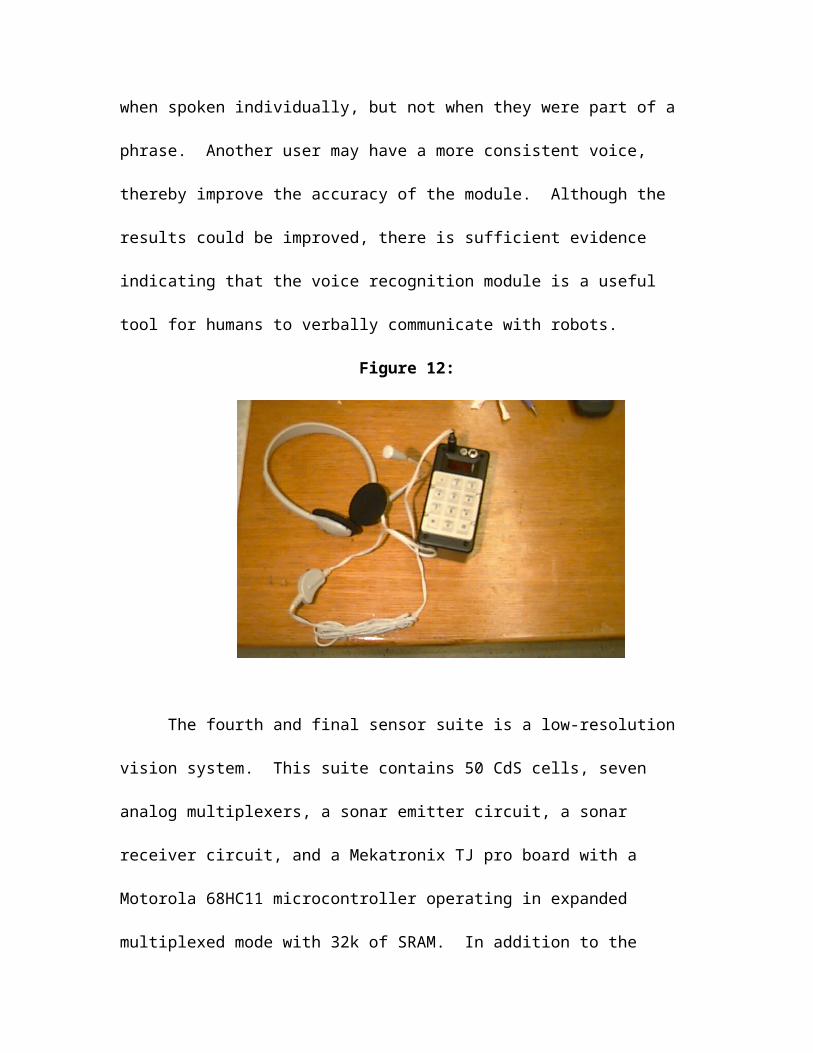
As indicated from the above data, the device works best when simple phrases are
used. This may be attributed to the fact that individual words may have been over-
emphasized when spoken individually, but not when they were part of a phrase. Another
user may have a more consistent voice, thereby improve the accuracy of the module.
Although the results could be improved, there is sufficient evidence indicating that the
voice recognition module is a useful tool for humans to verbally communicate with
robots.
Figure 12:

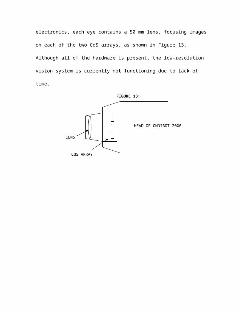
The fourth and final sensor suite is a low-resolution vision system. This suite
contains 50 CdS cells, seven analog multiplexers, a sonar emitter circuit, a sonar receiver
circuit, and a Mekatronix TJ pro board with a Motorola 68HC11 microcontroller
operating in expanded multiplexed mode with 32k of SRAM. In addition to the
electronics, each eye contains a 50 mm lens, focusing images on each of the two CdS
arrays, as shown in Figure 13. Although all of the hardware is present, the low-resolution
vision system is currently not functioning due to lack of time.
FIGURE 13:
LENS
CdS ARRAY
HEAD OF OMNIBOT 2000

Behaviors
Omnibot 2000 is currently capable of four behaviors. These include obstacle
avoidance, wall following, obeying commands, entertaining. The behaviors are selected
by issuing voice commands to the robot. By saying, “Begin avoid” the robot will start its
avoidance behavior. The other behaviors are started in a similar fashion. The robot
repeats the words that it hears, so the user will know if the robot has understood the
command correctly. Once a complete command is understood, the robot will then say a
phrase indicating that it has understood the commands, and then executes the instructions.
The first three behaviors use the sensors to determine the actions of the robot,
while the last two are simply “shows.” The avoidance behavior uses four IR emitters and
detectors. Two are in the front of the robot, and two are in the rear. The sensors return a
value between 88 and 120. There are no objects being detected when 88 is returned, and
when 128 is returned the sensors are saturated. There is an avoidance threshold set at
100, and when the sensors return a value higher than that, the robot turns away from the
corresponding high sensor direction. Additionally, if the sensors in the rear return a value
higher than the avoidance threshold, the robot speeds up to get away from the object.
This is obstacle avoidance behavior.
The wall following behavior uses the other four IR emitters and detectors. Two
are on the left side, and two are on the right side. The values returned by the detectors on
a side are compared to the threshold, and when the forward detector is above it and the
rear detector is below it, the robot starts to turn away, and vice-versa. This situation is
the same for the left and right sides.

The next behavior is obeying commands, is “slave” mode. The robot will listen to
spoken instructions, and then do as it is told. The words are used in combinations to
make up phrases. The phrases that Omnibot 2000 will understand are:
1. ROTATE(21) LEFT(13) SHOULDER(24) PITCH(32) MINUS(34) <AMOUNT>
2. ROTATE(21) LEFT(13) SHOULDER(24) PITCH(32) PLUS(35) <AMOUNT>
3. ROTATE(21) LEFT(13) SHOULDER(24) YAW(33) MINUS(34) <AMOUNT>
4. ROTATE(21) LEFT(13) SHOULDER(24) YAW(33) PLUS(35) <AMOUNT>
5. ROTATE(21) LEFT(13) ELBOW(25) MINUS(34) <AMOUNT>
6. ROTATE(21) LEFT(13) ELBOW(25) PLUS(35) <AMOUNT>
7. ROTATE(21) LEFT(13) WRIST(23) MINUS(34) <AMOUNT>
8. ROTATE(21) LEFT(13) WRIST(23) PLUS(35) <AMOUNT>
9. ROTATE(21) RIGHT(14) SHOULDER(24) PITCH(32) MINUS(34) <AMOUNT>
10. ROTATE(21) RIGHT(14) SHOULDER(24) PITCH(32) PLUS(35) <AMOUNT>
11. ROTATE(21) RIGHT(14) SHOULDER(24) YAW(33) MINUS(34) <AMOUNT>
12. ROTATE(21) RIGHT(14) SHOULDER(24) YAW(33) PLUS(35) <AMOUNT>
13. ROTATE(21) RIGHT(14) ELBOW(25) MINUS(34) <AMOUNT>
14. ROTATE(21) RIGHT(14) ELBOW(25) PLUS(35) <AMOUNT>
15. ROTATE(21) RIGHT(14) WRIST(23) MINUS(34) <AMOUNT>
16. ROTATE(21) RIGHT(14) WRIST(23) PLUS(35) <AMOUNT>
17. ROTATE(21) HEAD(26) MINUS(34) <AMOUNT>
18. ROTATE(21) HEAD(26) PLUS(35) <AMOUNT>
19. ROTATE(21) NECK(27) MINUS(34) <AMOUNT>
20. ROTATE(21) NECK(27) PLUS(35) <AMOUNT>
21. BODY(15) LEFT(13) <AMOUNT>
22. BODY(15) RIGHT(14) <AMOUNT>
23. BODY(15) FORWARD(11) <AMOUNT>

24. BODY(15) BACKWARD(12) <AMOUNT>
35. GRIPPER(22) LEFT(13) MINUS(34) <AMOUNT>
36. GRIPPER(22) LEFT(13) PLUS(35) <AMOUNT>
37. GRIPPER(22) RIGHT(14) MINUS(34) <AMOUNT>
38. GRIPPER(22) RIGHT(14) PLUS(35) <AMOUNT>
<AMOUNT> indicates that the user is to say two digits, each zero through nine,
indicating the position the servo is to move to. However, when issuing any commands
that start with the command word, “BODY” <AMOUNT> indicates the amount of time
the robot is to move in the specified direction in tenths of a second. For example, if the
user wanted the robot to look straight ahead (head_pan servo equal to 0 degrees), the
command would be, “ROTATE HEAD MINUS ZERO ZERO.” If the user wanted the
robot to move forward for half a second, the command would be, “BODY FORWARD
ZERO FIVE.” By using these commands, the user can have Omnibot 2000 perform basic
assistive tasks.
The final behavior was developed to make Omnibot capable of giving a
PowerPoint presentation, or sing and dance to a song. The user programs in the spoken
text, in combination with body movements, and Omnibot 2000 will give a presentation or
sing and dance. There is a function in the code, mouse_click(), that causes Omnibot to
press the mouse button. However, Omnibot can not hold the mouse on its own; a rubber
band is needed to secure it in place. To start this behavior, the user states the command
words, “BEGIN SHOW.” Additionally, this behavior gives Omnibot the capability to
dance. The lyrics to the song YMCA were programmed into Omnibot, along with the
body gestures. When the correct command words are spoken, Omnibot 2000 will sing
and dance to YMCA.

Conclusion
Omnibot 2000 was a great learning experience. I learned about mechanical
design, electrical design, and software design. I also learned how to integrate everything
and what problems may arise from combining different systems together to create a
robot.
Omnibot 2000 is capable of intelligent, autonomous behavior. It can avoid
bumping into objects, and if it does hit something, it then back up, turns, and continues
on. It can also follow walls in combination with obstacle avoidance, so it can follow the
walls of a room and still avoid bumping into things. Additionally, Omnibot 2000 is great
for entertainment. People are fascinated when they watch it, so it attracts a large
audience, and it fits the stereotypical image of a robot.
Although it is great for entertaining, it does not work well enough to help people.
The control methods are too complex, the voice recognition can not perform consistently,
and the mechanical structure has faults. The robot is a “proof of concept.” It proves that
all of these ideas can be integrated into an autonomous working robot. It also exposes
faults in the ideas and some of the original theory behind its conception.
If I were going to built Omnibot again, some things that can be improved include
the mechanical design, electrical design, and overall control methodologies. A more
robust mechanical structure, with more degrees of freedom, better end effectors, and a
better locomotion system would satisfy the mechanical problems. The new structure,
combined with a faster processor, more memory, and better sensors would be good
enough for a new platform. The control system should be improved; higher level

commands would simplify controlling Omnibot. This also includes better voice
recognition, because the current system is not consistent enough for a reliable robot.
In spite of the downfalls, Omnibot 2000 is a great robot. Many ideas were
implemented in the design, and some were successful, some were not. At times of
failure, I would question all of the hard work and effort I was putting into the building of
this robot. Luckily, the accomplishments outweigh all of the failures I had. I would like
to build another robot similar to Omnibot 2000, and I can say that I have learned from my
mistakes and the next robot will show this.

ABSTRACT
Omnibot 2000 is the name of the robot I built for EEL 5666, Intelligent Machines Design Laboratory, during the summer of 1999. The robot is designed to be a personal assistant, capable of helping the elderly or disabled. Additionally, Omnibot 2000 can entertain and perform. Its behaviors include obstacle avoidance, wall following, obeying commands, and performing. The user, using voice recognition determines the behaviors. The user issues commands to the robot, and the robot responds by repeating the words, and then performing the specified behavior. The robot contains four different sensor suits, including infrared emitters and detectors, bump switches, voice recognition, and low-resolution vision. During wall following behavior, Omnibot will turn away from objects in its path. When it is doing wall following, it will follow the walls of a room, and it will also avoid bumping into obstacles. When the robot is in its obeying commands behavior, the user can instruct the robot to move its arms, grippers, head, and body. The robot is a slave, performing any tasks the user requests. When it is told to dance, it will start singing and dancing to YMCA, or any other song programmed. Additionally, the robot was programmed to give my oral presentation.
Executive Summary
Omnibot 2000 was an old toy manufactured about 10 years ago by a toy company
named Tomy. It was designed to be a toy, controlled by a hand held transmitter. The
original design was not autonomous, the user had to control the actions of the robot by
pushing buttons on the controller. The robot now has four different behaviors: obstacle
avoidance, wall following, obeying commands, and entertaining. It also had only five
degrees of freedom: the head could pan, the left shoulder pitch could rotate, the left
gripper could open and close, and the wrist could rotate. I modified the original design
by adding seven more degrees of freedom, for a total of 12. The head can now pan and
tilt, each shoulder can now rotate about its pitch and yaw axis, both elbows can rotate
about their pitch axis, both grippers can open and close, and both wrists can rotate. After
redesigning the mechanical structure, I removed all of the stock electronics and added
three Motorola 68HC11 microcontrollers. Two operate in expanded multiplexed mode,
while the third operates in single chip mode. One of the expanded mode processors is
used for the low-resolution vision system, while the other is used as the main controller
of the robot. The single chip controller generates the signals required to control the
servos. I also added a voice synthesizer module, voice recognition, infrared (IR) emitters
and detectors, and bump sensors. The voice recognition is used to control the behaviors,
as well as issue commands to the robot while it is in “slave” mode. The IR emitters and
detectors are used for obstacle avoidance and wall following. The entertaining behavior
does not any of the sensors. Omnibot 2000 is a successful performer, but the poor
performance of the voice recognition limits the effectiveness of the robot when it is
obeying commands. Fortunately, it does a great job at giving PowerPoint presentations.
Omnibot 2000
Final Report
Scott NortmanUniversity of Florida
Department of Electrical and Computer EngineeringEEL 5666
Intelligent Machines Design LaboratorySummer, 1999

Table of Contents
Abstract………………………………………………………………..Page 3
Executive Summary…………………………………………………...Page 4
Introduction……………………………………………………………Page 5
Integrated System……………………………………………………..Page 6
Mobile Platform……………………………………………………….Page 8
Actuation and Output Devices………………………………………..Page 10
Sensors………………………………………………………………..Page 15
Behaviors……………………………………………………………..Page 25
Conclusion……………………………………………………………Page 28
Omnibot 2000 C Code…………………………………………...Appendix A
Datasheets…………………………………………………...…...Appendix B

APPENDIX A

APPENDIX B

Introduction
Many people who are sick or elderly require special care or assistance when
trying to perform certain tasks. Maybe someone who is sick can not grab an item that
was dropped or are immobile and con not get it himself or herself. That is what Onmibot
2000 is designed to do: help people. Because the mechanical structure resembles a
human, controlling the robot is intuitive and easy for people to learn. Additionally,
because the robot is controlled by voice command, it is easy to use for people who are in
need.
The goal of Onmibot 2000 was to design an intelligent autonomous agent that
could move around, not bump into things, and help people. The robot would be capable
of providing assistance, with an easy to use interface. As an added feature, the robot
would also be able to entertain by singing and dancing.
These features are all available on Omnibot 2000. The following paper discusses
the ideas and goals for the project. It then talks about the problems encountered, as well
as the improvements made over the original design. Finally, the paper ends by talking
about the accomplished goals and ideas for the future.


