25
Integrated Top-down Design & Diagnostic Software Toolkit for Minimizing Network Complexity Xin Sun [email protected] Florida International University

Integrated Top-down Design & Diagnostic Software Toolkit for
Minimizing Network Complexity
Xin Sun
Florida International University
Research Direction One Eliminating unnecessary complexity of new
networks:
comprehensive complexity-aware top-
down design
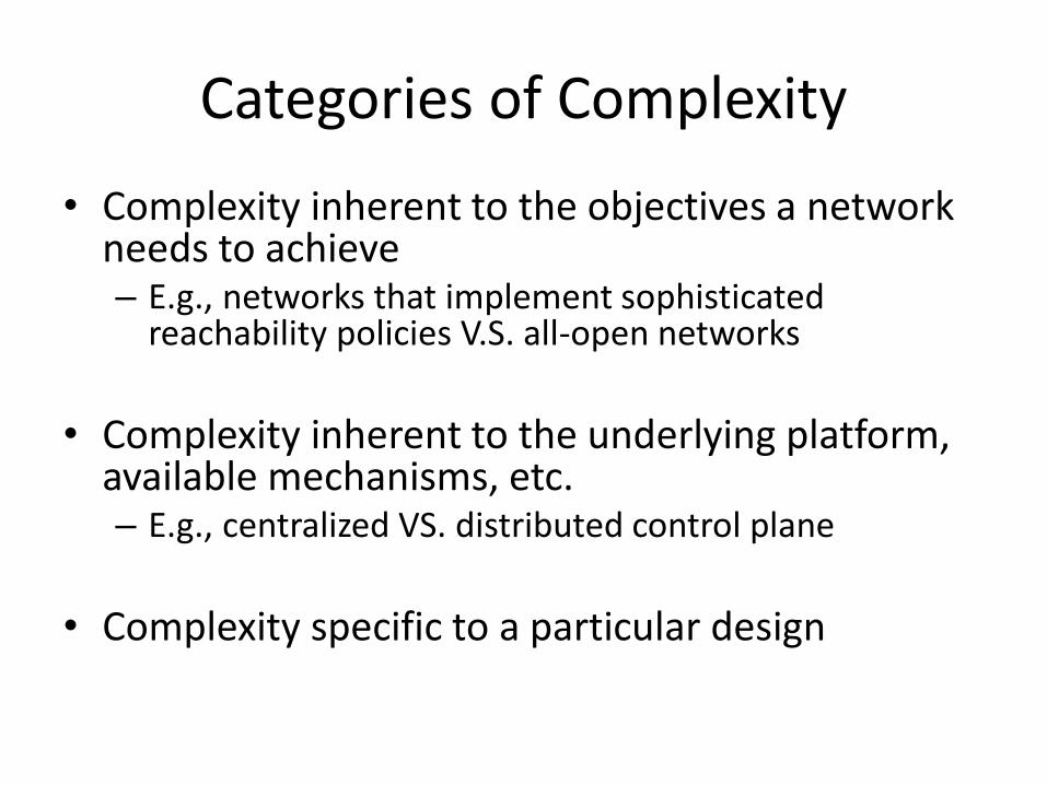
Categories of Complexity
• Complexity inherent to the objectives a network needs to achieve – E.g., networks that implement sophisticated
reachability policies V.S. all-open networks
• Complexity inherent to the underlying platform,
available mechanisms, etc. – E.g., centralized VS. distributed control plane
• Complexity specific to a particular design
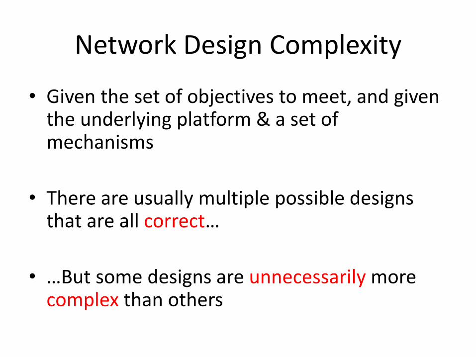
Network Design Complexity
• Given the set of objectives to meet, and given the underlying platform & a set of mechanisms
• There are usually multiple possible designs that are all correct…
• …But some designs are unnecessarily more complex than others

An Illustrating Example
……
can only be accessed by
Three VLANs can be created.
Available IP blocks: 10.0.1/24, 10.0.2/24, 10.0.3/24
H1—H20
H21—H40
H41—H60
H61—H80
H81—H100

VLAN Background
• Extensively used in enterprise networks. • A VLAN groups end hosts in disparate locations into a
single broadcast domain – By constructing a spanning tree that spans all the hosts
• A VLAN becomes a subnet at layer-3, and is assigned a continuous IP block. (typically /24)
• Total number of VLANs is bounded by both hardware capacity, and available IP blocks

Design #1
……
Permit H1 … Permit H20 Permit H41 … Permit H60 Permit H81 … Permit H100 Permit VLAN 30
VLAN 10 (10.0.1/24)
VLAN 20 10.0.2/24
VLAN 30 (10.0.3/24)
H1—H20
H21—H40
H41—H60
H61—H80
H81—H100
too many rules at individual IP level
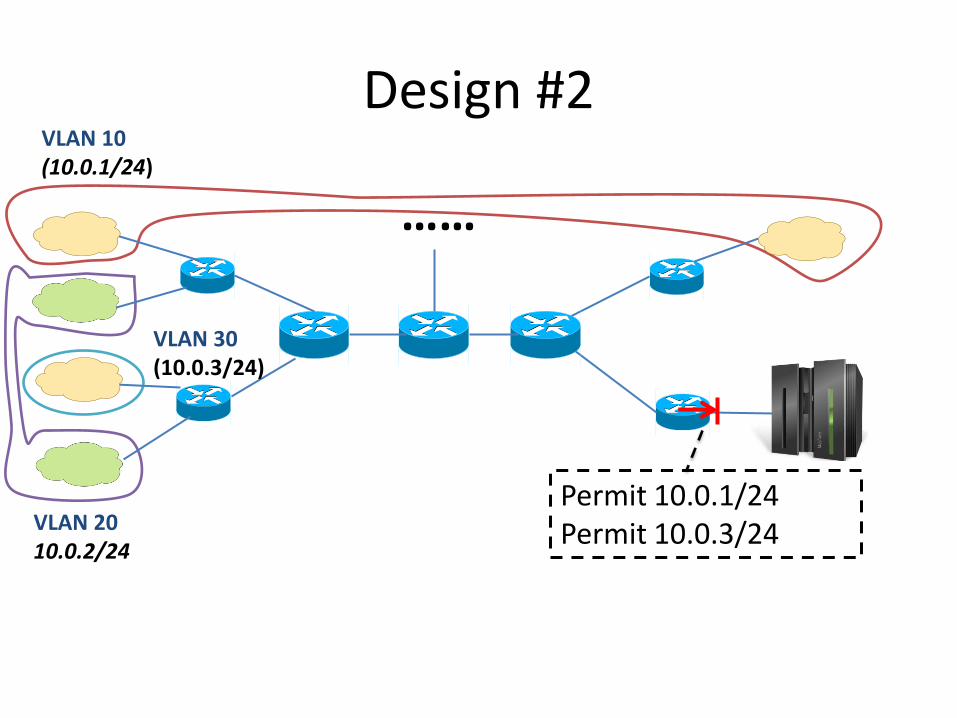
Design #2
……
VLAN 10 (10.0.1/24)
Permit 10.0.1/24 Permit 10.0.3/24 VLAN 20
10.0.2/24
VLAN 30 (10.0.3/24)

Design #2
……
VLAN 10 (10.0.1/24)
Permit 10.0.1/24 Permit 10.0.3/24 VLAN 20
10.0.2/24
VLAN 30 (10.0.3/24)
Switchport mode trunk allow 10
+ Much fewer rules, all at subnet level
- Too many VLAN trunk links
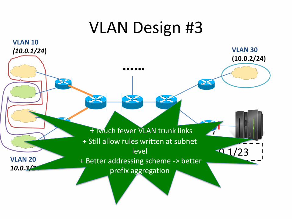
VLAN Design #3
……
Permit 10.0.1/23
VLAN 10 (10.0.1/24)
VLAN 20 10.0.3/24
VLAN 30 (10.0.2/24)
+ Much fewer VLAN trunk links
+ Still allow rules written at subnet level
+ Better addressing scheme -> better prefix aggregation
Insight from the Example
• Given the same design objectives to be achieved, and the same set of available mechanisms, there are multiple correct designs. However some designs are unnecessarily more complex than others
• Both VLAN design & addressing scheme have impact on the final packet filter complexity. – The designs of VLAN, address allocation & packet filter
are interconnected

Current Practice
• Network design remains a largely ad-hoc process – Operators are guided by simple rules-of-thumb, past experiences and
intuition
• Considered network design as consisting of isolated “stages” or
“tasks” – Focusing on one stage at a time, and trying to optimizing that stage
independently… – …Without systematically considering how the design decision made in
one stage will impact the complexity of other stages – E.g. 1, some design guidelines recommend always grouping nearby
hosts into VLANs – E.g. 2, we observed one network maintains a strict mapping between
prefix and VLAN ID (i.e., VLAN 10 -> a.b.10/24, VLAN 20-> a.b.20/24, etc.)

Our Approach: complexity-aware comprehensive Top-down Design
• A systematic design approach that Jointly considers interconnected design tasks to minimize complexity – By modeling the impact of one task on other tasks
• Preliminary work applied this approach to: – VLAN design & packet filters
– addressing scheme & packet filters
• Objectives – Minimizing complexity in the resulting network (measured by total # of filter
rules & VLAN trunk links)
– Ensuring reachability policies are correctly enforced.
• Constraints – Total number of VLANs
– Available IP space
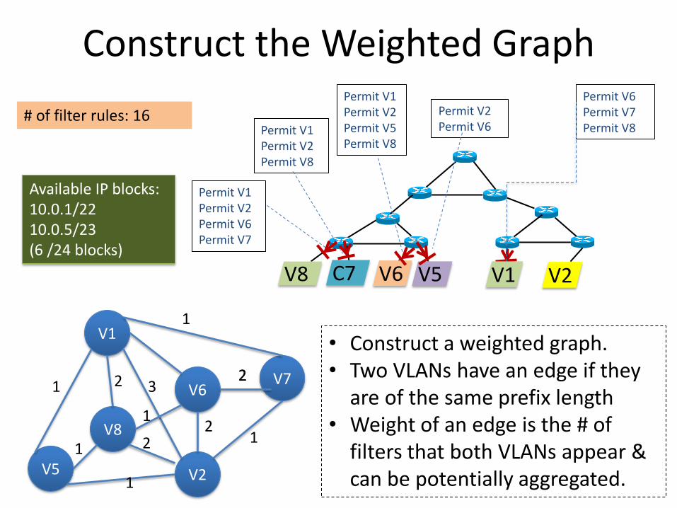
Construct the Weighted Graph
# of filter rules: 16
V8 V6 C7 V5 V2
Permit V2 Permit V6
Permit V1 Permit V2 Permit V5 Permit V8
Permit V1 Permit V2 Permit V8
Permit V1 Permit V2 Permit V6 Permit V7
Permit V6 Permit V7 Permit V8
V1
V2
V7 V6
V8
V5
• Construct a weighted graph. • Two VLANs have an edge if they
are of the same prefix length • Weight of an edge is the # of
filters that both VLANs appear & can be potentially aggregated.
1
2 2
2 1
3 2
2
1
1
1
1
V1
Available IP blocks: 10.0.1/22 10.0.5/23 (6 /24 blocks)
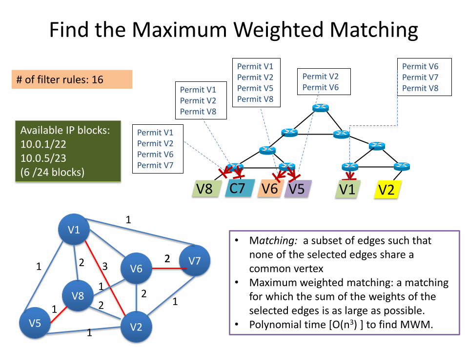
Find the Maximum Weighted Matching
# of filter rules: 16
V8 V6 C7 V5 V2
Permit V2 Permit V6
Permit V1 Permit V2 Permit V5 Permit V8
Permit V1 Permit V2 Permit V8
Permit V1 Permit V2 Permit V6 Permit V7
Permit V6 Permit V7 Permit V8
V1
Available IP blocks: 10.0.1/22 10.0.5/23 (6 /24 blocks)
V1
V2
V7 V6
V8
V5
1
2 2
2 1
3 2
2
1
1
1
1
• Matching: a subset of edges such that none of the selected edges share a common vertex
• Maximum weighted matching: a matching for which the sum of the weights of the selected edges is as large as possible.
• Polynomial time [O(n3) ] to find MWM.
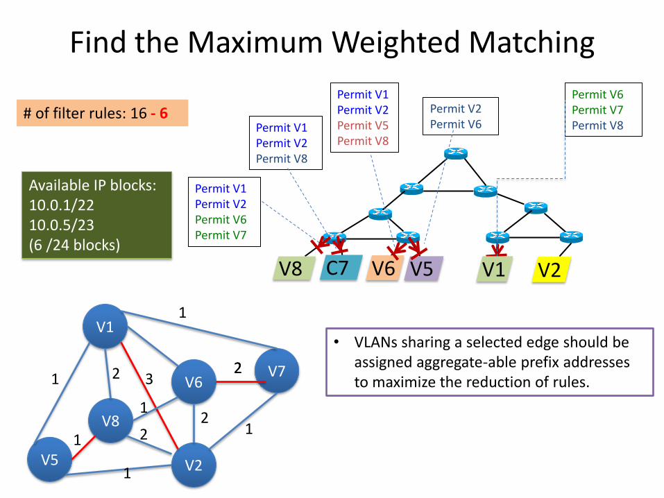
Find the Maximum Weighted Matching
# of filter rules: 16
V8 V6 C7 V5 V2
Permit V2 Permit V6
Permit V1 Permit V2 Permit V5 Permit V8
Permit V1 Permit V2 Permit V8
Permit V1 Permit V2 Permit V6 Permit V7
Permit V6 Permit V7 Permit V8
V1
Available IP blocks: 10.0.1/22 10.0.5/23 (6 /24 blocks)
V1
V2
V7 V6
V8
V5
1
2 2
2 1
3 2
2
1
1
1
1
• VLANs sharing a selected edge should be assigned aggregate-able prefix addresses to maximize the reduction of rules.
- 6

This Process Continues (to Aggregate at Larger Prefixes)
# of filter rules: 16 - 6
V8 V6 C7 V5 V2
Permit V2 Permit V6
Permit V1 Permit V2 Permit V5 Permit V8
Permit V1 Permit V2 Permit V8
Permit V1 Permit V2 Permit V6 Permit V7
Permit V6 Permit V7 Permit V8
V1
Available IP blocks: 10.0.1/22 10.0.5/23 (6 /24 blocks)
V1, V2
V6, V7
V5, V8
1 1

This Process Continues (to Aggregate into Larger Prefixes)
# of filter rules: 16 - 6
V8 V6 C7 V5 V2
Permit V2 Permit V6
Permit V1 Permit V2 Permit V5 Permit V8
Permit V1 Permit V2 Permit V8
Permit V1 Permit V2 Permit V6 Permit V7
Permit V6 Permit V7 Permit V8
V1
Available IP blocks: 10.0.1/22 10.0.5/23 (6 /24 blocks)
V1, V2
V6, V7
V5, V8
1 1 • Assign 10.0.1/22 to V1, V2, V6, V7
assign 10.0.1/23 to V1, V2, and 10.0.3/23 to V6, V7
• Assign 10.0.5/23 to V5, V8
- 1
Summary
• Focused on eliminating unnecessary complexity in the design of a network – Resulted from the ad-hoc, complexity-agnostic design process
• Our approach: a systematic top-down design framework that.. – Jointly considers interconnected design tasks – Explicitly considers complexity in the resulting design – Overall approach is to formulate the design process as a set of
optimization problems (enables automating the design process)
• Presented one building block of this top-down design framework

Research Direction Two Lowering complexity of existing networks:
complexity root-cause diagnostics
(in collaboration with Michael Behringer, Alexander Clemm and Alberto Prieto @ Cisco)

Toolkit for Complexity Root Cause Diagnosis
• Given an existing network, we want to find out the characteristics in its design that introduce most of the operational complexity – E.g., a flat mesh-like topology is likely to make installing packet filters harder
than a clean hierarchical topology – E.g., a flat topology is also likely to make troubleshoot connectivity issues
harder.
• Overall approach is to automatically correlate the observed symptoms of complexity, to identify the root causes in the underlying design – Step 1: assess the complexity of the network. Key idea is to run a set of
benchmark operations. – Step 2: correlate the observed symptoms of complexity to identify the root
causes
• Main challenge: there could potentially exist many causes of complexity, and operators won’t have time to fix all of them – Solution: rank the identified causes, based on (i) their impact on complexity;
and (ii) the cost of fixing each of them.
• Many research questions are to be answered, and we are currently addressing these questions as our ongoing work.
Designing Benchmark Operations to Assess Complexity
• Benchmarks must reflect common components in a variety of operations which contribute most of the complexity
• Two common components we identified:
– Information collection
– Setting up parameters

Benchmark for Information Collection
• Consider an operation of “blocking communication between Engineering & Financial”.
• Operator needs to find out: – The IP address space of both departments (to derive filter
rules) • Not in configuration, but documented/maintained separately, e.g.,
in an external database
– All the possible paths between the two departments (to determine the filter placement) • Obtain pair-wise device connectivity through CDP/LLDP, then
manually construct the end-to-end paths

Benchmark for Parameterization
• The configuration process can be viewed as (i) the procedure itself plus (ii) setting up certain parameters
– The procedure part can be easily automated through use of templates
– The parameterization part must be done manually, and thus contribute most of the complexity in configuration.


![The Texas Clinician’sPostpartum Depression Toolkit€¦ · The Diagnostic and Statistical Manual of Mental Disorders (5th ed.; DSM-5; American Psychiatric Association [APA], 2013)](https://static.documents.pub/doc/80x56/605c5a05416cb73a0c2cf548/the-texas-clinicianaspostpartum-depression-toolkit-the-diagnostic-and-statistical.jpg)


