Joachim Rodrigues, EIT, LTH, Introduction to Structured VLSI Design [email protected]VHDL I Introduction to Structured VLSI Design ‐ VHDL I Joachim Rodrigues Joachim Rodrigues, EIT, LTH, Introduction to Structured VLSI Design [email protected]VHDL I VHDL Very High Speed Integrated Circuit (VHSIC) Hardware Description Language A Technology Independent, Standard Hardware description Language (HDL), used for digital system modeling, simulation, and synthesis Joachim Rodrigues, EIT, LTH, Introduction to Structured VLSI Design [email protected]VHDL I Why VHDL? There are several hardware description languages available; VHDL (Europe), Verilog (USA), and System C are the most common. Advantages of VHDL • IEEE standard. • Supported by all CAD Tools. • Technology independent. • Common – Specially in Europe. • Flexible – Delay modeling, Matrices, etc. • Supports easy modeling of various abstraction levels. Joachim Rodrigues, EIT, LTH, Introduction to Structured VLSI Design [email protected]VHDL I VHDL History • 1981 – VHSIC Initiated (US DoD) • 1985 – VHDL version 7.2 (IBM and TI) • 1987 – IEEE standard, VHDL 1076 – 1987 • 1993 – Revised standard, VHDL 1164 – 1993 (std_logic_1164) • 2008 ‐ Accellera approved VHDL 4.0 also informally known as VHDL 2008
Transcript
Joachim Rodrigues, EIT, LTH, Introduction to Structured VLSI Design [email protected] VHDL I
Introduction to Structured VLSI Design‐ VHDL I
Joachim Rodrigues
Joachim Rodrigues, EIT, LTH, Introduction to Structured VLSI Design [email protected] VHDL I
VHDL
Very High Speed Integrated Circuit (VHSIC)
Hardware
Description
Language
A Technology Independent, Standard Hardware description Language (HDL), used for digital system modeling, simulation, and synthesis
Joachim Rodrigues, EIT, LTH, Introduction to Structured VLSI Design [email protected] VHDL I
Why VHDL?
There are several hardware description languages available; VHDL (Europe), Verilog (USA), and System C are the most common.
Advantages of VHDL• IEEE standard.• Supported by all CAD Tools.• Technology independent.• Common – Specially in Europe. • Flexible – Delay modeling, Matrices, etc. • Supports easy modeling of various abstraction levels.
Joachim Rodrigues, EIT, LTH, Introduction to Structured VLSI Design [email protected] VHDL I
• 2008 ‐ Accellera approved VHDL 4.0 also informally known as VHDL 2008
Joachim Rodrigues, EIT, LTH, Introduction to Structured VLSI Design [email protected] VHDL I
VHDL History
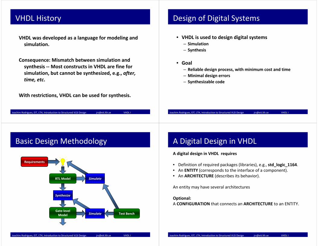
VHDL was developed as a language for modeling and simulation.
Consequence: Mismatch between simulation and synthesis ‐‐Most constructs in VHDL are fine for simulation, but cannot be synthesized, e.g., after, time, etc.
With restrictions, VHDL can be used for synthesis.
Joachim Rodrigues, EIT, LTH, Introduction to Structured VLSI Design [email protected] VHDL I
Design of Digital Systems
• VHDL is used to design digital systems– Simulation– Synthesis
• Goal– Reliable design process, with minimum cost and time– Minimal design errors– Synthesizable code
Joachim Rodrigues, EIT, LTH, Introduction to Structured VLSI Design [email protected] VHDL I
Basic Design Methodology
Requirements
SimulateRTL Model
Gate‐levelModel
Synthesize
Simulate Test Bench
Simulate
Synthesize
Simulate
Joachim Rodrigues, EIT, LTH, Introduction to Structured VLSI Design [email protected] VHDL I
A Digital Design in VHDLA digital design in VHDL requires
• Definition of required packages (libraries), e.g., std_logic_1164.• An ENTITY (corresponds to the interface of a component).• An ARCHITECTURE (describes its behavior).
An entity may have several architectures
Optional:A CONFIGURATION that connects an ARCHITECTURE to an ENTITY.
Joachim Rodrigues, EIT, LTH, Introduction to Structured VLSI Design [email protected] VHDL I
Entity ‐ Adder
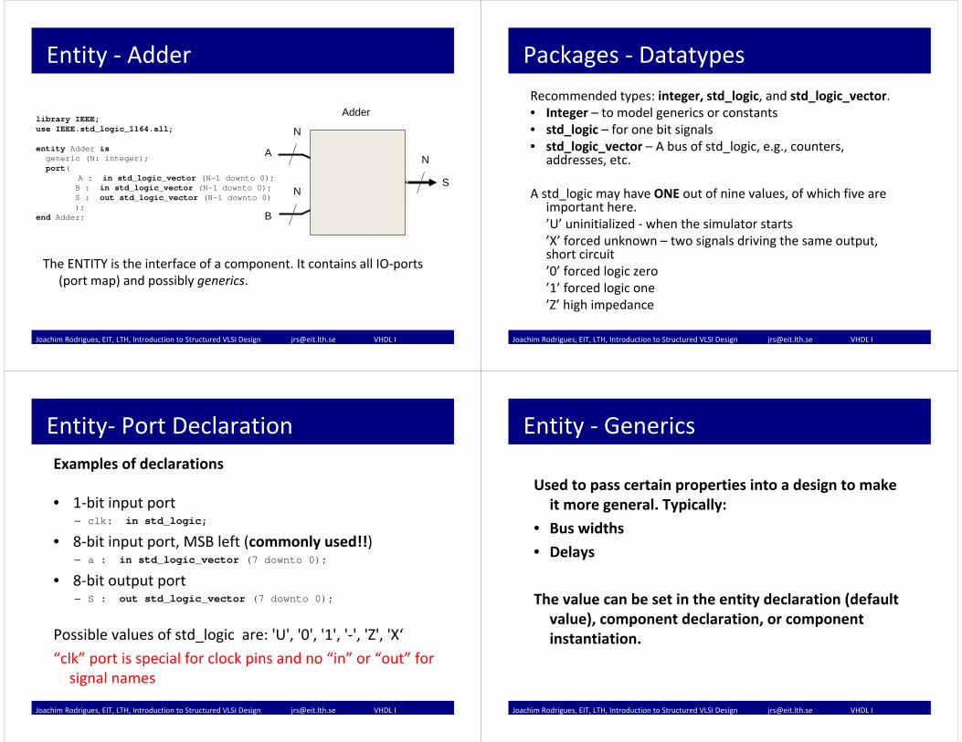
The ENTITY is the interface of a component. It contains all IO‐ports (port map) and possibly generics.
library IEEE;use IEEE.std_logic_1164.all;entity Adder is
generic (N: integer);port(
A : in std_logic_vector (N-1 downto 0);B : in std_logic_vector (N-1 downto 0);S : out std_logic_vector (N-1 downto 0));
end Adder; B
S
A
+
Adder
N
N
N
Joachim Rodrigues, EIT, LTH, Introduction to Structured VLSI Design [email protected] VHDL I
Packages ‐ Datatypes
Recommended types: integer, std_logic, and std_logic_vector.• Integer – to model generics or constants• std_logic – for one bit signals• std_logic_vector – A bus of std_logic, e.g., counters,
addresses, etc.
A std_logic may have ONE out of nine values, of which five are important here.’U’ uninitialized ‐ when the simulator starts’X’ forced unknown – two signals driving the same output, short circuit’0’ forced logic zero’1’ forced logic one’Z’ high impedance
Joachim Rodrigues, EIT, LTH, Introduction to Structured VLSI Design [email protected] VHDL I
Entity‐ Port DeclarationExamples of declarations
• 1‐bit input port– clk: in std_logic;
• 8‐bit input port, MSB left (commonly used!!)– a : in std_logic_vector (7 downto 0);
• 8‐bit output port– S : out std_logic_vector (7 downto 0);
Possible values of std_logic are: 'U', '0', '1', '‐', 'Z', 'X‘
“clk” port is special for clock pins and no “in” or “out” for signal names
Joachim Rodrigues, EIT, LTH, Introduction to Structured VLSI Design [email protected] VHDL I
Entity ‐ Generics
Used to pass certain properties into a design to make it more general. Typically:
• Bus widths
• Delays
The value can be set in the entity declaration (default value), component declaration, or component instantiation.
Joachim Rodrigues, EIT, LTH, Introduction to Structured VLSI Design [email protected] VHDL I
Architecture• An architecture is:
– a pattern, a template, a way of doing it
• Developing a good architecture involves:– Coordination and optimization across many levels of abstraction.
– ...under a large set of constraints and requirements (that is changing over time).
– An iterative process involving design and analysis. “Exploring the design space”.
Joachim Rodrigues, EIT, LTH, Introduction to Structured VLSI Design [email protected] VHDL I
ArchitectureBasically two types of architectures:
• Behavioral: using sequential processes• Structural: top level, component instantiation, concurrent
processes
Behavioral
Behav.
Behavioral
Beh.
Be.
Behav.
Be.
Fully behavioral
Partially beh. & struct.
Pipelined structural
Joachim Rodrigues, EIT, LTH, Introduction to Structured VLSI Design [email protected] VHDL I
B
A
Adder
N
N
N
Architecture ‐ behavioral
architecture behavioral ofADDER is
beginadd_a_b : process (A,B) begin
s <= A+B;end process add_a_b;
end architecture behavioral;
S+
Architecture defines behavior of the circuit
Joachim Rodrigues, EIT, LTH, Introduction to Structured VLSI Design [email protected] VHDL I
Architecture ‐ behavioral
• Behavioral architecture– Describes the algorithm performed by the module, FSM
– May contain• Process statements
• Sequential statements
• Signal assignment statements
• Wait statements (not synthesizable)
Joachim Rodrigues, EIT, LTH, Introduction to Structured VLSI Design [email protected] VHDL I
Architecture ‐ Structural
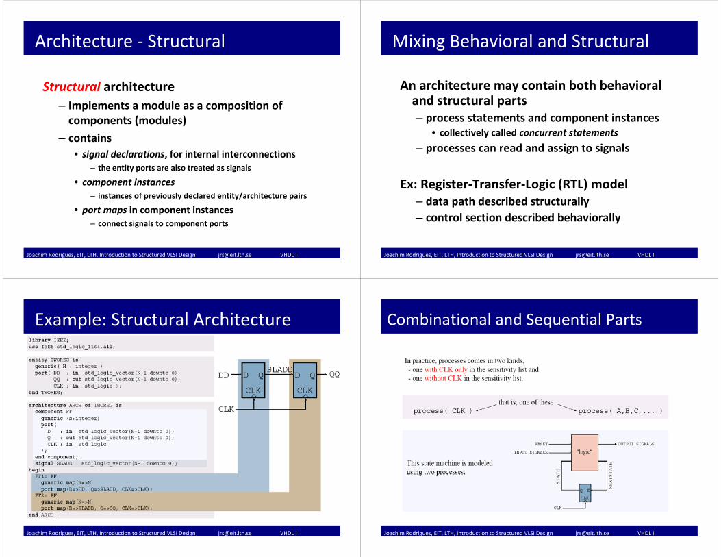
Structural architecture– Implements a module as a composition of components (modules)
– contains• signal declarations, for internal interconnections
– the entity ports are also treated as signals
• component instances– instances of previously declared entity/architecture pairs
• port maps in component instances– connect signals to component ports
Joachim Rodrigues, EIT, LTH, Introduction to Structured VLSI Design [email protected] VHDL I
Mixing Behavioral and Structural
An architecture may contain both behavioral and structural parts– process statements and component instances
• collectively called concurrent statements
– processes can read and assign to signals
Ex: Register‐Transfer‐Logic (RTL) model– data path described structurally– control section described behaviorally
Joachim Rodrigues, EIT, LTH, Introduction to Structured VLSI Design [email protected] VHDL I
Example: Structural Architecture
Joachim Rodrigues, EIT, LTH, Introduction to Structured VLSI Design [email protected] VHDL I
Combinational and Sequential Parts
Joachim Rodrigues, EIT, LTH, Introduction to Structured VLSI Design [email protected] VHDL I
Concurrent Statements and Processes
• Concurrent statements (simple processes):– a <= b;– c <= a + b;– d <= a And B;
• Process statements:
namelabel: process (a, b, … sensitivity list)variable declarations…beginsequential statements…
– if … then … [else | elsif …] end if;– for n in 0 to 7 loop…– case b is …– s := z sll shamt;– i := a + b; ‐‐variable assignment, only in processes– c <= i; ‐‐concurrent signal assignment!end process namelabel;
•All processes are “executed” in parallel (think of gates and wires, not variables)
Joachim Rodrigues, EIT, LTH, Introduction to Structured VLSI Design [email protected] VHDL I
Process – Example I
Joachim Rodrigues, EIT, LTH, Introduction to Structured VLSI Design [email protected] VHDL I
Process – Example I (cont’d)
Joachim Rodrigues, EIT, LTH, Introduction to Structured VLSI Design [email protected] VHDL I
Process – Example II
process (clk, reset)begin
if clk’event and clk=’1’thenif (Reset = '0') thenQ <= '0';elseif enable=’1’ thenQ <= D;end if;
end if;end process ;
Enable register with synchrounus reset
Joachim Rodrigues, EIT, LTH, Introduction to Structured VLSI Design [email protected] VHDL I
Case command
• Example: Multiplexer
architecture behv1 of Mux isbeginprocess(I3,I2,I1,I0,S) --nested in processbegin -- use case statement
case S iswhen "00" => Op <= I0; --sequential statementswhen "01" => Op <= I1; when "10" => Op <= I2; when "11" => Op <= I3; when others => Op <= "ZZZ"; --avoid inferred latches
end case; end process; end behv1;
Joachim Rodrigues, EIT, LTH, Introduction to Structured VLSI Design [email protected] VHDL I
IF vs. CASE statements
If and case statements generate different HW
If statementIf (c1= ’1’) then
q <= a;Elseif (c2 = ’1’) then
q <= b;Else q <= c;End if;
b
Mux
q
Mux
c
a
c2c1
Case statementCase c iswhen ”01” => q <= a;when ”10” => q <= b;when others => q <= c;
End case;
b
Mux q
c
c
a
Joachim Rodrigues, EIT, LTH, Introduction to Structured VLSI Design [email protected] VHDL I
Finite State Machines
Why FSMs?– Models different behavoiur at different times (states)
A state machine requires:– An initial state (Reset)– Transitions with stable states– Default values (Case statement)
Joachim Rodrigues, EIT, LTH, Introduction to Structured VLSI Design [email protected] VHDL I
FSM Structure
• A FSM can be split in three parts:– State Transition Logic block
– State Memory block (register)
– Output logic
Joachim Rodrigues, EIT, LTH, Introduction to Structured VLSI Design [email protected] VHDL I
Summary
• Signals have a delta‐delay if not other delay is specified
• Variables are updated instantaneously• Statements in
– an architecture body are concurrent– a process are sequential
• Components need to be declared before instantiation
• FSMs are implemented using CASE statements
Joachim Rodrigues, EIT, LTH, Introduction to Structured VLSI Design [email protected] VHDL I
Inferred Latches• In case a process does not assign an output signal value:
– The old value is retained– This is an inferred latch and the circuit is no longer combinational– The latch is not explicit but is inferred from the VHDL code– Normally caused by failure to consider all combinations– Bad programming practice
Bad1: process(sA,sB,a,b)begin
if sA=’1’ then z<=a;
elsif sB=’1’ thenz<=b;
end if;end process Bad1;
good: process(select,a,b)begin
if select=’1’ then z<=a;
elsez<=b;
end if;end process Mux;
a
b
select
za
b
sA sB
zL
OR
Bad2: process(sA,a,b)begin
if sA=’1’ then f<=a;
end if;end process Bad2;
Joachim Rodrigues, EIT, LTH, Introduction to Structured VLSI Design [email protected] VHDL I
Simulation / Synthesis mismatch?
• For all combinational processes (no clock):– All process input signals must be in the sensitivity list.– Synthesis tools usually ignore the sensitivity list, but simulators don’t!– Wrong sensitivity list will cause mismatch in behavior between functional
simulation and the synthesized circuit.
Wrong: process (select,b)begin
if select=’1’ then z<=a;
elsez<=b;
end if;end process Wrong;
Mux: process (select,a,b)begin
if select=’1’ then z<=a;
elsez<=b;
end if;end process Mux;
a
b
select
za
b
select
zL Both versions
synthesize to the circuit to the right.
Joachim Rodrigues, EIT, LTH, Introduction to Structured VLSI Design [email protected] VHDL I
Summary
The knowledge you have gained today is sufficient to implement a simple combinational or structural architecture.
Joachim Rodrigues, EIT, LTH, Introduction to Structured VLSI Design [email protected] VHDL I
Testbench and Simulation• Testing: Testbench and Circuit
– The testbench models the environment our circuit is situated in.
– Provides stimuli (input to circuit) during simulation.– May verify the output of our circuit against test vectors.
• The testbench (VHDL) consists of:– A top level entity connecting the circuit to the testbench– One or more behavioral architectures (matching the refined
level of our circuit).• Testing is done at every abstraction level.
Testbench
Circuit
Joachim Rodrigues, EIT, LTH, Introduction to Structured VLSI Design [email protected] VHDL I
Testbench and SimulationTesting larger circuits
• Divide and conquer
testbench
circuit
3 subcomponents ‐> 3 subtests:
testbench A testbench Ctestbench B
Test (simulation) fails !
What then ?
How can I find the bug ?
This will localize the problem or problems! Repeat the procedure if a faulty component consists of subcomponents, etc.
Joachim Rodrigues, EIT, LTH, Introduction to Structured VLSI Design [email protected] VHDL I
• Test strategy ‐> documentation of design correctness.• Good design = easy to test ‐> a good design is a well‐
structured well‐partitioned hierarchical design.– Tip: Do not overdo it with too many entities!
• Design and test of pipelined circuits
• With a good testbench it is also easy to verify that the final synthesized design works as specified.
Pipelined-circuit
testbench
One stage
testbench
Testbench and SimulationTesting larger circuits
Joachim Rodrigues, EIT, LTH, Introduction to Structured VLSI Design [email protected] VHDL I
Testbench Example
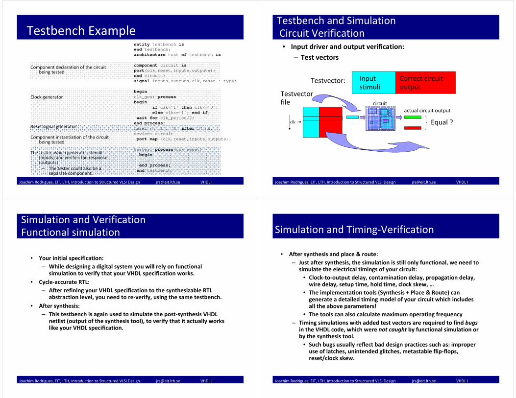
Component declaration of the circuit being tested
Clock generator
Reset signal generator
Component instantiation of the circuit being tested
The tester, which generates stimuli (inputs) and verifies the response (outputs)
– The tester could also be a separate component.
entity testbench isend testbench;architecture test of testbench iscomponent circuit isport(clk,reset,inputs,outputs);end circuit;signal inputs,outputs,clk,reset : type;
beginclk_gen: processbegin
if clk=’1’ then clk<=’0’;else clk<=’1’; end if;
wait for clk_period/2;end process;reset <= ‘1’, ‘0’ after 57 ns;device: circuitport map (clk,reset,inputs,outputs);
tester: process(clk,reset)begin….
end process;end testbench;
Joachim Rodrigues, EIT, LTH, Introduction to Structured VLSI Design [email protected] VHDL I
Testbench and SimulationCircuit Verification• Input driver and output verification:
– Test vectors
circuit
Input stimuli
Correct circuit output
Testvector:
Testvector file
actual circuit output
clk Equal ?
Joachim Rodrigues, EIT, LTH, Introduction to Structured VLSI Design [email protected] VHDL I
Simulation and VerificationFunctional simulation
• Your initial specification:– While designing a digital system you will rely on functional
simulation to verify that your VHDL specification works.• Cycle‐accurate RTL:
– After refining your VHDL specification to the synthesizable RTL abstraction level, you need to re‐verify, using the same testbench.
• After synthesis:– This testbench is again used to simulate the post‐synthesis VHDL
netlist (output of the synthesis tool), to verify that it actually works like your VHDL specification.
Joachim Rodrigues, EIT, LTH, Introduction to Structured VLSI Design [email protected] VHDL I
Simulation and Timing‐Verification
• After synthesis and place & route:– Just after synthesis, the simulation is still only functional, we need to
simulate the electrical timings of your circuit:• Clock‐to‐output delay, contamination delay, propagation delay, wire delay, setup time, hold time, clock skew, …
• The implementation tools (Synthesis + Place & Route) can generate a detailed timing model of your circuit which includes all the above parameters!
• The tools can also calculate maximum operating frequency– Timing simulations with added test vectors are required to find bugs
in the VHDL code, which were not caught by functional simulation or by the synthesis tool.
• Such bugs usually reflect bad design practices such as: improperuse of latches, unintended glitches, metastable flip‐flops, reset/clock skew.
Joachim Rodrigues, EIT, LTH, Introduction to Structured VLSI Design [email protected] VHDL I
What’s next?
• Contin ue sequence detector
• Find a lab buddy
• 2nd VHDL presentation Tuesday next week
First Deadline: Preparation of sequence detector Monday 7th
Joachim Rodrigues, EIT, LTH, Introduction to Structured VLSI Design [email protected] VHDL I