A Dissertation Presented to the Faculty of the School of Engineering and Applied Science at the University of Virginia In Partial Fulfillment of the Requirements for the Degree Doctor of Philosophy (Computer Science) by Integrating Fault-Tolerance Techniques in Grid Applications Anh Nguyen-Tuong August 2000
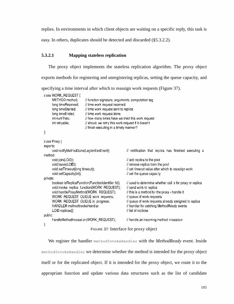
Transcript
A Dissertation
Presented to
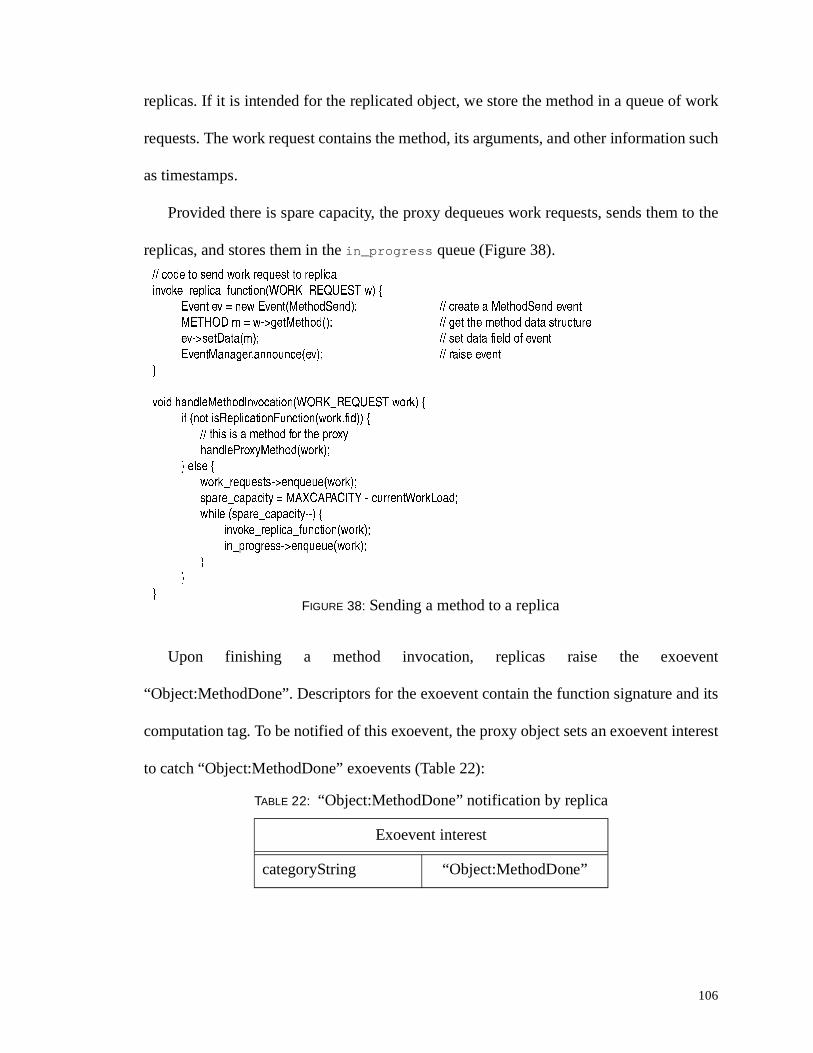
the Faculty of the School of Engineering and Applied Science
at the
University of Virginia
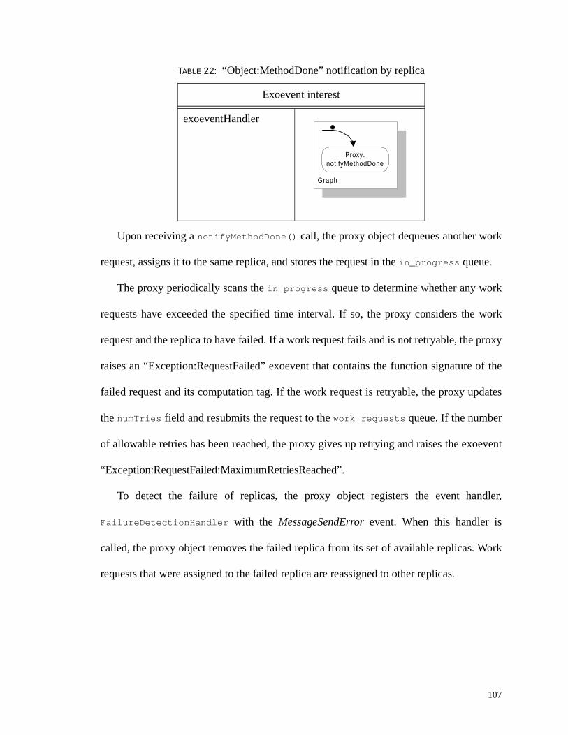
In Partial Fulfill ment
of the Requirements for the Degree
Doctor of Philosophy (Computer Science)
by
Integrating Fault-Tolerance Techniques in Gr id Applications
in-fra-struc-ture \'in-fre-,strek-cher, n (1927)The basic facili ties, services, and installations needed for the functioning of a community
or society, such as transportation and communications systems, water and power lines,and public institutions including schools, post offices, and prisons.
— American Heritage Dictionary
Chapter 1
Introduction
Throughout history, the development of infrastructures has catalyzed and shaped the
evolution of human progress. The construction of Roman roads, the telegraph, the
telephone, the modern banking system, the rail road, the interstate highway system, the
electrical power grids, and the Internet, are all successful infrastructures that have
revolutionized how people communicate and interact. At the dawn of the new millennium,
we are witnessing the birth of what promises to be the next revolutionary infrastructure.
Funded in the United States by several governmental agencies, including the National
Science Foundation (NSF), the Defense Advanced Research Project Agency (DARPA),
the Department of Energy (DOE), and the National Aeronautics and Space Administration
(NASA), this new infrastructure is often referred to as a metasystem or computational grid
[GRIM97A, SMAR97, GRIM98, FOST99, LEIN99].
A computational grid is a specialized instance of a distributed system [MULL93,
TANE94] with the following characteristics: compute and data resources are
geographically distributed; they are under the control of different administrative domains
2
with different security and accounting policies; and the hardware resource base is
heterogeneous and consists of PCs, workstations and supercomputers from different
manufacturers. The abilit y to develop applications over this environment is sometimes
referred to as the wide-area computing problem [GRIM99].
Computational grids present a complex environment in which to develop applications.
Writing a grid application is at least as difficult as writing an application for traditional
distributed systems. Thus, since both are fundamentally distributed memory systems,
programmers must deal with issues of application distribution, communication and
synchronization. Furthermore, grids present additional challenges as programmers may be
required to deal with issues such as security, disjoint file systems, fault tolerance and
placement, to name only a few [GRIM98, FOST99, GRIM99]. Without additional higher
level abstractions, all but the best programmers will be overwhelmed by the complexity of
the environment.
The contribution of this work is the development of a framework for simpli fying the
construction of grid applications. The framework provides a generic extension mechanism
for incorporating functionality into applications and consists of two models: (1) the
reflective graph and event model, and (2), the exoevent notification model. These models
provide a platform for extending user applications with additional capabiliti es via
composition. While the models are generic and can be used for a variety of purposes,
including security, resource accounting, debugging, and application monitoring [VILE97,
FERR99, LEGI99, MORG99], we apply the models in this dissertation towards the
integration of fault-tolerance techniques. Support for the development of fault-tolerant
3
applications has been identified as one of the major technical challenges to address for the
successful deployment of computational grids [GRIM98, FOST99, LEIN99].
Consider application reliabilit y in a grid. As applications scale to take advantage of a
grid’s vast available resources, the probabilit y of failure is no longer negligible and must
be taken into account. For example, consider an application decomposed into 100 objects,
with each object requiring one week of processing time and placed on its own workstation.
Assuming that each workstation has an exponentially distributed failure mode with a
mean-time-to-failure of 120 days, the mean-time-to-failure of the entire application would
only be 1.2 days, thus, the application would rarely finish!
Using the framework, fault-tolerance experts can encapsulate algorithms using the two
reflective models developed in this dissertation. Developers incorporate these algorithms
into their tools and augment the set of services provided to application programmers.
Application programmers then use these augmented tools to increase the likelihood that
their programs will complete successfully.
We claim that the framework enables the easy integration of fault-tolerance techniques
into object-based grid applications. To support this claim, we have mapped onto our
models five different fault-tolerance algorithms from the literature: 2PCDC and SPMD
checkpointing, passive and stateless replication, and pessimistic method logging. We
chose these algorithms to il lustrate the applicabilit y of our framework to a range of fault-
tolerance techniques. Furthermore, we selected these algorithms because we believe that
they are likely to be used in grid applications. We incorporated these algorithms into three
common grid programming tools: Message Passing Interface (MPI), Mentat, and Stub
Generator (SG). MPI is the de facto standard for message passing; Mentat is a C++-based
4
parallel programming environment; and SG is a popular tool for writing client/server
applications.
We measured the ease by which techniques can be integrated into applications based
on the number of additional li nes of code that a programmer would have to write. In the
best case, programmers needed to add three lines of code. In the worst case, programmers
had to write functions to save and restore the local state of their objects. However, such
functions are simple to write and exploit programmers’ knowledge of their applications.
Furthermore, tools to automate save and restore state functions have already been
demonstrated in the literature [BEGU97, FERR97, FABR98].
To the best of our knowledge, we are the first to advocate and use a reflective
architecture to structure applications in computational grids. Moreover, we are the first to
demonstrate the integration of a wide range of fault-tolerance techniques into grid
applications using a single framework.
1.1 Current support for fault tolerance in gr ids
Until recently, the foremost priority for grid developers has been to develop working
prototypes and to show that applications can be written over a grid environment
[GRIM97B, BRUN98, FOST98]. To date, there has been limited support for application-level
fault tolerance in computational grids. Support has consisted mainly of failure detection
services [STEL98, GROP99] or fault-tolerance capabilities in specialized grid toolkits
[NGUY96, CASA97]. Neither solution is satisfactory in the long run. The former places the
burden of incorporating fault-tolerance techniques into the hands of application
programmers, while the latter only works for specialized applications. Even in cases
5
where fault-tolerance techniques have been integrated into programming tools, these
solutions have generally been point solutions, i.e., tool developers have started from
scratch in implementing their solution and have not shared, nor reused, any fault-tolerance
code.
As these tools are ported to grid environments, or as new tools are developed for grid
environments, the continued development of fault-tolerant tools as point solutions
represents wasteful expenditure. We believe a better approach is to provide a structural
framework in which tool developers can integrate fault-tolerance solutions via a
compositional approach in which fault-tolerance experts write algorithms and encapsulate
them into reusable code artifacts, or modules. Tool developers can then integrate these
modules in their environments.
1.2 Properties of the framework
Our long-term goal is to simpli fy the construction of fault-tolerant grid applications.
We believe that a good solution for achieving this goal should exhibit the following
properties:
• P1. Separation of concerns and composition. Designing and writing fault-
tolerance code are complex and error-prone tasks and should be done by experts,
not application programmers or tool developers. Thus, fault-tolerance experts
should be able to encapsulate algorithms into reusable and composable code
artifacts [NGUY99]. Furthermore, the incorporation of fault-tolerance techniques
should not interfere with other non-functional concerns such as security or
accounting.
• P2. Localized cost. By localized cost, we mean that the use of resources or services
to implement fault-tolerance techniques should not be charged to applications that
6
do not require those resources or services—users should pay only for the level of
services that they need. In general, localized cost is an important attribute for any
grid services [GRIM97A].
• P3. Working proof of concept. We should be able to demonstrate the integration of
fault-tolerance techniques in running applications on a working grid prototype and
using multiple programming tools. Further, applications with fault-tolerance
techniques integrated should be able to tolerate more failures than applications that
do not use any fault-tolerance techniques.
1.3 Evaluation
Based on our goal of simpli fying the construction of fault-tolerant applications and the
properties listed in §1.2, we have derived several criteria by which to evaluate our
framework (next to each criterion, we note in parenthesis its related property):
• Multiple programming tools. A successful solution should promote and enable the
incorporation of fault-tolerance techniques into multiple programming tools,
including legacy tools such as MPI or PVM. Legacy tools are already familiar to
programmers and should ease the transition from traditional distributed systems to
grid environments. (P1, P3)
• Breadth of fault-tolerance techniques. A successful solution should support a wide
range of fault-tolerance techniques so that application programmers may use the
one that is most appropriate for their needs. (P1, P2)
• Ease of use. Incorporating fault-tolerance techniques should required only trivial
or small modifications to applications. (P1, P3)
• Localized cost. Application programmers should select and pay only for the level
of fault tolerance that they require. A good framework should not impose a
system-wide solution. Instead, the cost of using fault-tolearnce techniques should
be localized to the applications that use these techniques. (P2)
• Overhead. Is the overhead of using fault-tolerance techniques due to the algorithm
or to the framework itself? In deciding whether to incorporate a fault-tolerance
7
technique, users should only worry about the algorithmic overhead, i.e., the cost of
the algorithm itself. (P2, P3)
1.4 Background
1.4.1 Gr id models
Before describing our framework, we present the implementation models of
computational grids. As shown in Figure 1, a grid consists of services that run on top of
native operating systems. These services provide functionality such as authentication,
failure detection, object and process management, and remote input/output, and are
accessed via grid libraries. Typically, an application programmer will not access these
libraries directly, but will use a programming tool such as MPI [GROP99],
NetSolve [CASA97], Ninf [SATO97] or MPL [GRIM97B], which in turn will call the
underlying grid libraries. The advantage of this layered model is that application
programmers can use familiar programming tools and interfaces and are shielded from the
There are currently three approaches to building grids: the commodity approach, the
service approach, and the integrated architecture approach [FOST99]. In the commodity
approach, existing commodity technologies, e.g. HTTP, CORBA, COM, Java, serve as the
basic building blocks of the grid [ALEX96, BALD96, FOX96, CHRI97]. The primary
advantages of this approach are the use of industry standard protocols, allowing
programmers to ride the technology curve as improvements are made to these protocols.
Furthermore, standard protocols stand a better chance of being adopted by a large
community of developers. The problem with this approach is that the current set of
protocols may not be adequate to meet the requirements of computational grids. In the
service approach, as exempli fied by the Globus project, a set of basic services such as
security, communication, and process management are provided and exported to
developers in the form of a toolkit [FOST97]. In the integrated architecture approach,
resources are treated and accessed through a uniform model of abstraction [GRIM98]. As
we describe in §1.4.3, our framework targets the integrated approach.
1.4.2 Reflection
Our framework relies on the observation that although fault-tolerance techniques are
diverse by nature, their implementation is not. Indeed, the implementation of the major
famili es of fault-tolerance techniques rely on common basic primitives such as:
• intercepting the message stream
• piggybacking information on the message stream
• acting upon the information contained in the message stream
• saving and restoring state
• detecting failure
• exchanging protocol information between participants of an algorithm
9
Thus, by providing an execution model whereby these primitives can be expressed and
manipulated as first class entities, it is possible to achieve our goals of developing fault-
tolerance capabili ties independently and integrating them into programming tools.
We use reflection as the architectural principle behind our execution models. Smith
introduced the concept of reflection as a computational process that can reason about itself
and manipulate representations of its own internal structure [SMIT82]. Two properties
characterize reflective systems: introspection and causal connection.* Introspection
allows a computational process to have access to its own internal structures. Causal
connection enables the process to modify its behavior directly by modifying its internal
data structures—there is a cause-and-effect relationship between changing the values of
the data structures and the behavior of the process. The internal data structures are said to
reside at the metalevel while the computation itself resides at the baselevel. The metalevel
controls the behavior at the baselevel. In our case, the fault-tolerance capabiliti es are
expressed at the metalevel and control the underlying baselevel computation.
1.4.3 Legion gr id environment
Our work targets the Legion environment for multiple reasons: (1) Legion is object-
based, (2) it already uses graphs for inter-object communication, (3) it is an existing grid
prototype, and (4), multiple programming tools are available. None of the other
environments considered, such as Globus and CORBA-based systems, possess all these
attributes. However, our framework is also relevant to these other environments. For
example, it could be used to structure CORBA applications. Recent research has been
* Note that the term causal is used differently in the distributed systems literature where it refersto the “happen-before” relationship as defined by Lamport [LAMP78].
10
oriented towards extending the functionality of CORBA systems through a reflective
architecture [BLAI98, HAYT98, LEDO99]. Our work suggests that structuring CORBA-
reflective architectures using an event-based and/or graph-based paradigm is an idea
worth pursuing.
Legion treats all resources in a computation grid as objects that communicate via
asynchronous method invocations. Objects are address-space-disjoint, i.e., they are
logically-independent collections of data and associated methods. Objects contain a thread
of control, and are named entities identified by a Legion Object IDentifer (LOID). Objects
are persistent and can be in one of two states: active or inert. Active objects contain a
thread of control and are ready to service method calls. They are implemented with
running processes over a message passing layer. Inert objects exist as passive object state
representations on persistent storage. Legion moves objects between active and inert states
to use resources efficiently, to support object mobili ty, and to enable failure resili ence.
Legion objects are under the control of a Class Manager object that is responsible for
the management of its instances. A Class Manager defines policies for its instances and
regulates how an object is created, or deleted, and when it should be migrated, activated or
deactivated. By defining new Class Managers, grid developers can change the
management policies of object instances. Class Managers themselves are managed by
higher-order class managers, forming a rooted hierarchy.
Legion provides several default objects to manage its resource base. The two basic
objects are Host Objects and Vault Objects, which correspond to processor and storage
resources in a traditional operating system. Host objects are responsible for running an
active object while vault objects are used to store inert objects. Legion allows
11
customization of all it s objects. Thus, a host object could represent compute resources that
exhibit varying degrees of reliabilit y and performance, e.g., a personal computer, a
workstation, a server, a cluster, or a queue-controlled supercomputer. Similarly a vault
object could represent a local disk, a RAID disk, or tertiary storage. A full description of
the Legion object model can be found in the literature [GRIM98].
1.5 Framework foundation
The key contribution of this work is the development of two reflective models that are
the foundations of our framework, the reflective graph and event model, and the exoevent
notification model. Together these models provide flexible mechanisms for structuring
applications and specifying the flow of information between objects that comprise an
application. Furthermore, the models enable information propagation policies to be bound
to applications at run-time. The flexibilit y of the models and the abilit y to defer the
binding of policy decisions are the differentiating features of our framework.
The reflective graph and event model (RGE) reflects our target environment of (1) an
environment in which objects are implemented by running processes that communicate
via message passing, and (2) an object-based environment in which an application consists
of a set of cooperating objects. The RGE model employs graphs and events to expose the
structure of objects to fault-tolerance developers. It specifies both its external aspect
(interactions between objects) and its internal aspect (interaction inside objects). Graphs
and events are the building blocks with which fault-tolerance implementors can
incorporate functionali ty inside objects and exchange fault-tolerance protocol information
between objects. Graphs represent interactions between objects; a graph node is either a
12
member function call on an object or another graph, arcs model data or control
dependencies, and each input to a node corresponds to a formal parameter of the member
function. Events specify interactions inside objects and are used to structure their protocol
stack.
Our second model, the exoevent notification model, is a distributed event model.
Similarly to the event model defined by CORBA [BENN95] and the Java Distributed Event
Specification [SUN99A], the exoevent notification model provides a flexible mechanism
for objects to communicate. However, unlike the CORBA and Java models, the salient and
distinguishing features of the exoevent notification model are that it unifies the concept of
exceptions and events—an exception is a special case of an event—and it allows the
specification of event propagation policies to be set on a per-application, per-object or per-
method basis, at run-time. In our model, exoevents denote object state transitions and are
associated with program graphs. Raising an exoevent results in the execution of method
invocations on remote objects through the execution of associated program graphs—
hence the term exoevent. The abilit y to specify handlers as program graphs allows
developers to specify more complex policies than with a traditional event model.
The use of reflection to incorporate non-functional requirements has been proposed by
Stroud [STRO96]. Its use for integrating fault-tolerance capabilit ies into systems has been
successfully employed in many object-based systems, including FRIENDS [FABR98] and
GARF [GUER97]. Reflection has also been used as the basis for extending object
functionality in CORBA-based systems (OpenORB [BLAI98], FlexiNet [HAYT98],
OpenCorba [LEDO99]). The novelty of this dissertation is to suggest the use of events as
the primary structuring mechanism for designing object request brokers, the use of generic
13
program graphs to describe distributed event propagation policy and bind policy at run-
time, and the use of reflection to specify inter- and intra-object communication as generic
and flexible means of extending grid applications with additional functionality. In
particular, we focus on using the models to extend applications with fault-tolerance
capabiliti es.
1.5.1 Framework summary
In order to enable the integration of fault-tolerance techniques with applications, our
framework requires that both fault-tolerance experts and tool developers target the
reflective graph and event model and the exoevent notification model. Note that the
framework does not make any assumptions about the failure model used by the underlying
system, or the failure assumptions made by a given fault-tolerance algorithm. The
framework is an integration framework only; the decision as to whether a given algorithm
is suitable for a given application is not part of the framework proper.
Our framework imposes a unified structure on the way grid libraries are organized.
Specifically, our framework requires that library components use an event paradigm for
intra-object communication. The advantages of events in terms of flexibilit y and
extensibilit y are well-known. Events have been used in such diverse areas as graphical
user interfaces [NYE92], protocol stacks [BHAT97, HAYD98], operating system kernels
[BERS95] and integrated systems [SULL96]. Using events for building the protocol stack
of an object provides natural hooks for inserting fault-tolerance capabiliti es. In fact, the
events required to build a protocol stack for objects are those that are needed for
incorporating fault-tolerance functionality.
14
For inter-object communications, our model provides a data-driven, graph-based
abstraction. Graphs have been used successfully in parallel and distributed systems
[BABA92, BEGU92, GRIM96A]. Graphs enable the expression of traditional client/server
interactions, such as CORBA, as well as more complex interactions, such as pipelined
flow.
1.6 Constraints and assumptions
The fault-tolerance algorithms discussed in this dissertation make use of three
common assumptions: fail-stop, availabil ity of reliable storage, and reliable networks.
However, Legion only provides an approximation of these assumptions. Detecting a
crashed object is approximated using conservatively-set timeouts; reliable storage is
approximated with standard disks; and the use of a high-level retry mechanism for sending
messages is used to mask transient network partitions. Thus, it is possible for an
application using a given fault-tolerance technique to violate its failure assumptions. To
increase the likelihood that these assumptions are met, Legion could be configured to use
hosts and storage devices with higher reliabilit y, e.g., hosts such as those provided by the
NonStopTM Compaq®† or Stratus® architectures, storage such as RAID disks, and
possibly hosts configured with redundant network paths. However, we do not expect this
configuration to be common in grids in the near future. Thus, application developers
should be aware of the possibili ty of violating the failure assumptions—if the cost of
violating these assumptions is too high, e.g., as would be the case with safety-criti cal
applications, then these applications should not be used on Legion.‡ The framework
† Formerly known as Tandem®, acquired by Compaq Corporation.‡ Note that this comment applies to any computational grids.
15
described here is an integration framework only, and does not make any guarantees as to
the suitability of using a given algorithm. However, to increase the likelihood that the
failure assumptions are met, we configured applications to run within a site [DOCT99].
In this dissertation the algorithms we have mapped onto our framework are designed
to tolerate host failures. Computational grids use hardware resources owned by various
entities, including research labs, governmental agencies, and universities. At any moment
in time, it is thus not surprising to find that some hosts used by a grid system have crashed
due to someone rebooting the machine or tripping on a power cord; or by chance; or a host
may simply be down for maintenance. While the crash failure of hosts represents an
important class of failures in grids, we note that they are not the only source of failures—
unreliable software or operator error could also result in the failure of applications
[GRAY85]. Furthermore, we do not concern ourselves with non-fault-masking techniques
such as reconfiguration and presentation of alternative services to cope with failures
[HOFM94, KNIG98, GART99]. We are only concerned with the integration of fault-masking
techniques in grid applications. Once a host fails, we assume that it does not recover.
Furthermore, we seek only to integrate fault-tolerance techniques into user applications
and do not address the case of fault-tolerance for system-level objects.** We assume that
Legion services are always available.
1.7 Outline
We have organized the rest of the dissertation as follows. In Chapter 2, we present an
overview of related work in the areas of computational grids, reflection, event-driven
To understand how a fault-tolerance developer would incorporate functionality into
applications, we first present an example of a protocol stack configured using the event
paradigm [VILE97]. Then, we show an example of incorporating new functionali ty.
3.4.1 Overview of a protocol stack
Only a few events are needed to implement the core features of a protocol stack.† We
classify these events into three broad categories: message-related, method-related and
object management-related events. These events reflect our assumptions of an object-
based system in which communication is implemented over a message-passing fabric.
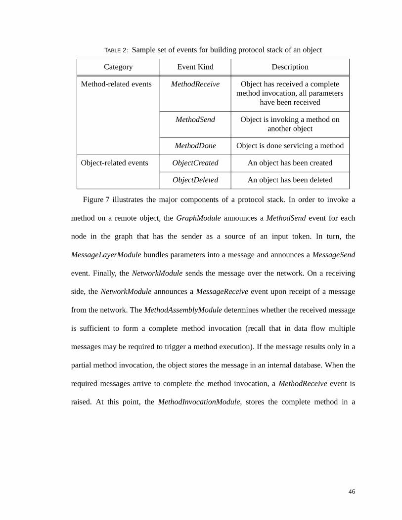
Table 2 describes the major event kinds used in configuring the protocol stack. The set of
events defines the vocabulary that designers can use to implement their algorithms.
† A more accurate description would be that of a protocol graph as events allow arbitraryconnections between modules. Nevertheless, we reuse the term protocol stack because of itsfamil iarity to most readers.
TABLE 2: Sample set of events for building protocol stack of an object
Category Event Kind Description
Message-related events MessageReceive Object has received a message
MessageSend Object is sending a message
MessageComplete Object has sent a messagesuccessfully
MessageError Error in sending message
46
Figure 7 ill ustrates the major components of a protocol stack. In order to invoke a
method on a remote object, the GraphModule announces a MethodSend event for each
node in the graph that has the sender as a source of an input token. In turn, the
MessageLayerModule bundles parameters into a message and announces a MessageSend
event. Finally, the NetworkModule sends the message over the network. On a receiving
side, the NetworkModule announces a MessageReceive event upon receipt of a message
from the network. The MethodAssemblyModule determines whether the received message
is suff icient to form a complete method invocation (recall that in data flow multiple
messages may be required to trigger a method execution). If the message results only in a
partial method invocation, the object stores the message in an internal database. When the
required messages arrive to complete the method invocation, a MethodReceive event is
raised. At this point, the MethodInvocationModule, stores the complete method in a
Method-related events MethodReceive Object has received a complete method invocation, all parameters
have been received
MethodSend Object is invoking a method on another object
MethodDone Object is done servicing a method
Object-related events ObjectCreated An object has been created
ObjectDeleted An object has been deleted
TABLE 2: Sample set of events for building protocol stack of an object
Category Event Kind Description
47
database of ready methods. A server loop may then extract ready methods from the
database and execute them.
3.4.2 Example of incorporating new functionality
We now show the ease with which a developer can add functionality to a user
application. Consider the case wherein a developer wishes to incorporate logging facilities
to record the exchange of methods in an application, perhaps to support post-mortem
debugging [MORG99] or fault-tolerance [NAMP99]. A simple way to implement this
functionality is to use implicit parameters to propagate the identity of a logger object.
Upon receiving a method, an object searches for the identity of the logger object in its
implicit parameter li st. If the object finds the identity of logger, it forwards the method to
the logger object prior to servicing the method.
Protocol Stack of Object using Modules
Network
Events
NetworkModule
MessageLayer
Module
GraphModule
MethodSend Event
MessageSend Event
NetworkModule
MethodAssembly
Module
MethodInvocation
Module
MessageReceive Event
MethodReceive Event
FIGURE 7: Structure of an object: sample protocol stack
48
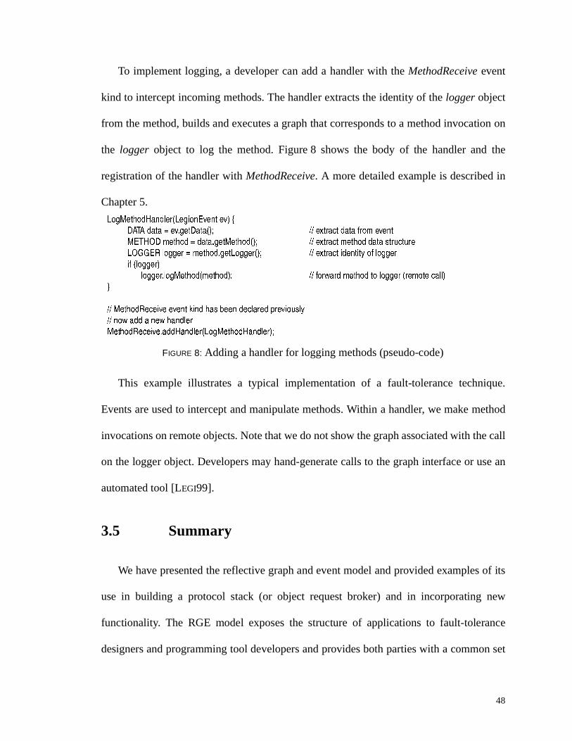
To implement logging, a developer can add a handler with the MethodReceive event
kind to intercept incoming methods. The handler extracts the identity of the logger object
from the method, builds and executes a graph that corresponds to a method invocation on
the logger object to log the method. Figure 8 shows the body of the handler and the
registration of the handler with MethodReceive. A more detailed example is described in
Chapter 5.
This example ill ustrates a typical implementation of a fault-tolerance technique.
Events are used to intercept and manipulate methods. Within a handler, we make method
invocations on remote objects. Note that we do not show the graph associated with the call
on the logger object. Developers may hand-generate calls to the graph interface or use an
automated tool [LEGI99].
3.5 Summary
We have presented the reflective graph and event model and provided examples of its
use in building a protocol stack (or object request broker) and in incorporating new
functionality. The RGE model exposes the structure of applications to fault-tolerance
designers and programming tool developers and provides both parties with a common set
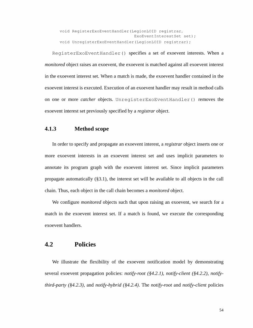
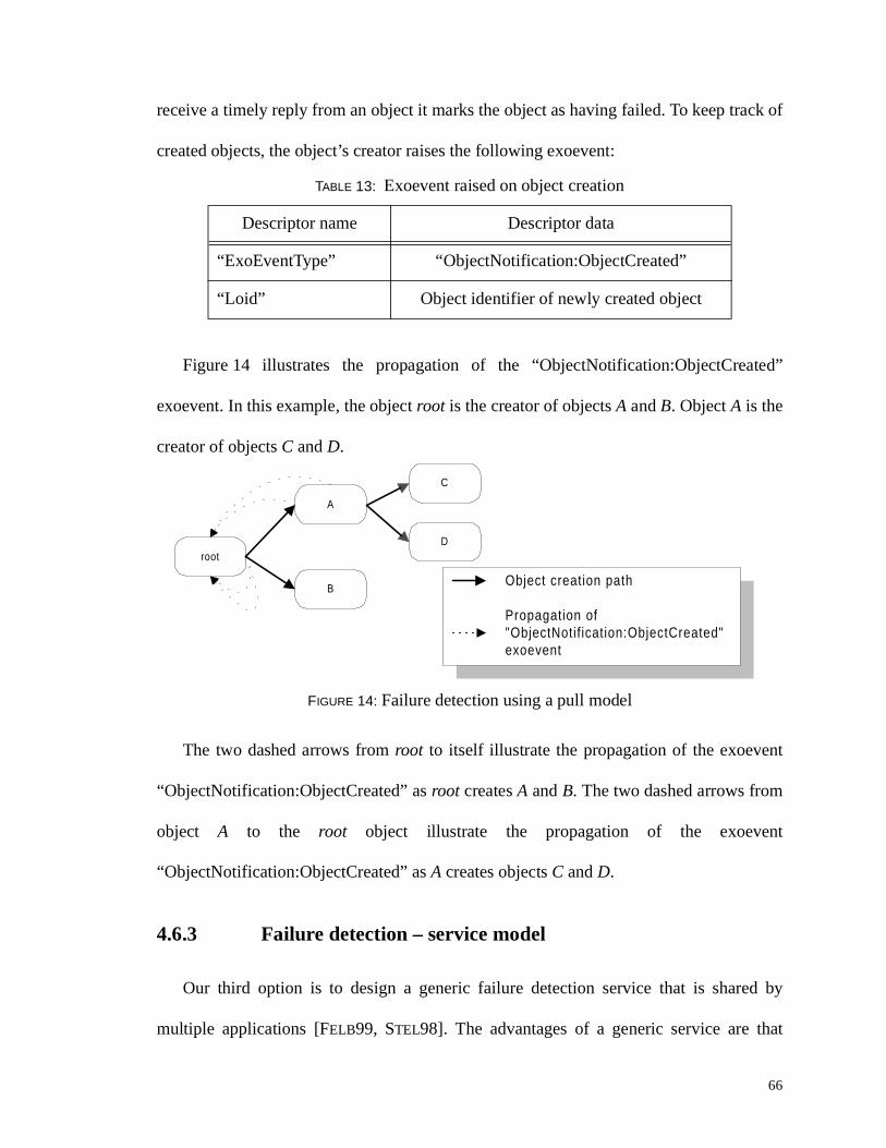
A commonly-used policy is for a root object to register to catch exoevents raised in an
application with the function:
LegionExoEventCat cherEnable(ExoEventInterest);
For more complex policies, e.g., masking exoevents (§4.2.2), users must create and
register the appropriate graphs with an exoevent interest using the interface described in
§3.1.1.
The full interface for using exoevents is shown in Figure12.
62
4.4 Overhead
Table 10 shows the overhead of creating and raising exoevents. The time required to
create an exoevent is 166 µs. The time to raise an exoevent is linearly proportional to the
number of exoevent interests in the exoevent interest set as we must inspect each exoevent
interest to find a match (~120 µs per exoevent interest).
FIGURE 12: API for exoevents
M N O P P Q R S T U V W X U W Y R V Z [\ \ O ] ] O ] R P M ^ T _ Z U ^ Z U Z ` R R X U R Y R V Z
T V P R ^ Z a R P M ^ T _ Z U ^ b c Z ^ T V S V O d R e a O Z O ] O Z O f g\ \ ^ R d U Y R ] R P M ^ T _ Z U ^
^ R d U Y R a R P M ^ T _ Z U ^ b c Z ^ T V S V O d R f g\ \ ^ R Z h ^ V P Z ` R ] O Z O O P P U M T O Z R ] i T Z ` j V O d R k
a O Z O S R Z a R P M ^ T _ Z U ^ b c Z ^ T V S V O d R f g\ \ P R Z Z ` R Z l _ R U m Z ` R R X U R Y R V Z\ \ R n h T Y O N R V Z Z U T V P R ^ Z a R P M ^ T _ Z U ^ b o R X U R Y R V Z p l _ R q e c Z ^ T V S f g
P R Z r Z l _ R b c Z ^ T V S f g\ \ S R Z Z ` R Z l _ R
c Z ^ T V S S R Z r Z l _ R b f g\ \ M U V P Z ^ h M Z U ^ s s Z l _ R T P Z ` R Z l _ R U m Z ` R R X U R Y R V Z\ \ R n h T Y O N R V Z Z U P R Z r Z l _ R b Z l _ R c Z ^ T V S f
Q R S T U V W X U W Y R V Z b c Z ^ T V S Z l _ R c Z ^ T V S f gt
M N O P P Q R S T U V W X U W Y R V Z u V Z R ^ R P Z [\ \ P _ R M T m l Z ` R v T V ] U m R X U R Y R V Z Z ` O Z i R O ^ R T V Z R ^ R P Z R ] T V
P R Z r M O Z R S U ^ l u V Z R ^ R P Z b c Z ^ T V S f g\ \ P R Z Z ` R S ^ O _ ` Z U w R R X R M h Z R ] T m Z ` R ^ R x P O d O Z M ` w R Z i R R V O V R X U R Y R V Z O V ] Z ` T P T V Z R ^ R P Z
P R Z r R X U R Y R V Z y O V ] N R ^ b z ^ O _ ` f g\ \ R X R M h Z R S ^ O _ ` T m Z ` R ^ R T P O d O Z M `
R X R M h Z R u m u V Z R ^ R P Z R ] b Q R S T U V W X U W Y R V Z f gt
\ \ M O Z M ` R X U R Y R V Z P U m Z l _ R j c Z ^ T V S k O V ] P R Z h _ m h V M Z T U V j m T ] k O P Z ` R M O N N w O M v m h V M Z T U VY U T ] Q R S T U V W X U W Y R V Z { O Z M ` R ^ W V O w N R b c Z ^ T V S e | h V M Z T U V u ] R V Z T m T R ^ m T ] f g\ \ ^ O T P R O V R X U R Y R V Z\ \ O Z Z R d _ Z Z U d O Z M ` Z ` R R X U R Y R V Z i T Z ` R O M ` R X U R Y R V Z T V Z R ^ R P Z P _ R M T m T R ] T V Z ` R P R Z\ \ O V ] R X R M h Z R O N N d O Z M ` R P
Q R S T U V } O T P R W X U W Y R V Z b Q R S T U V W X U W Y R V Z e Q R S T U V W X U W Y R V Z u V Z R ^ R P Z c R Z ~ � � Q Q f g
63
4.5 Example exoevents
In Table 11, we list seven examples of exoevents that developers can export. In
general, developers of programming tools should decide which of these exoevents are
relevant in their environments. The list below is not exhaustive; developers may export
other exoevents that are not listed here. Furthermore, except for “ExoEventType”, all
other descriptors shown are optional and can be incorporated at the discretion of tool
developers.
TABLE 10: Overhead in creating and raising exoevents
Test name Overhead
Time to create exoevent 166 µs
Time to raise exoevent (0 exoevent interest) 60 µs
Time to raise exoevent (1 exoevent interest) 184 µs
Time to raise exoevent (10 exoevent interests) 1181 µs
developers do not need to implement their own failure detection service and can select
from among different types of failure detectors. For example, some failure detectors may
be aggressive to declare failure while others may rely on special knowledge such as
network topology or network latency.
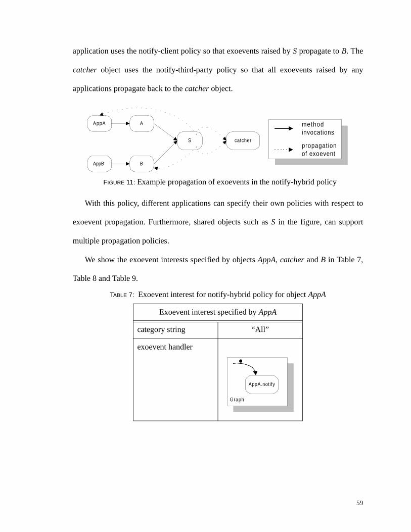
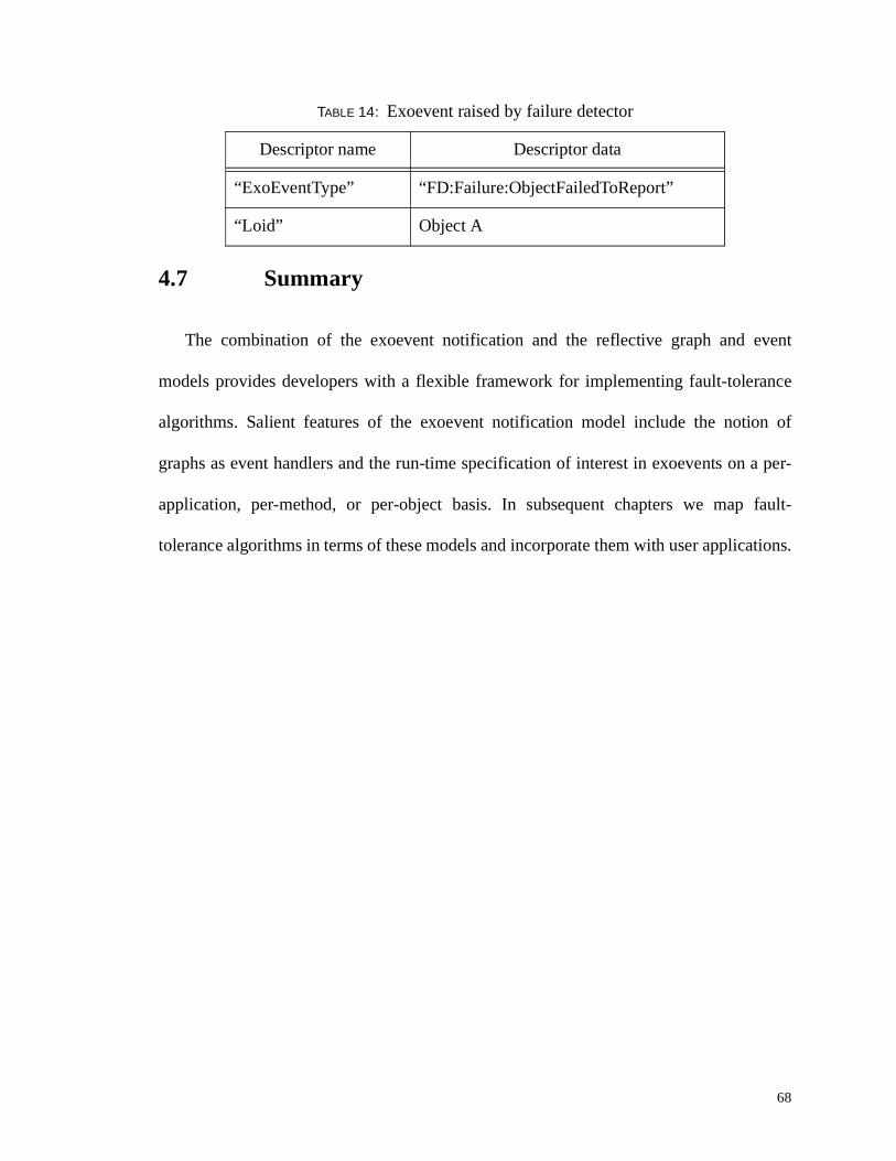
Figure 15 shows a failure detector object FD monitoring the status of four objects, A,
B, C, and D, using both the push and pull models as described in §4.6.1 and §4.6.2. FD
catches the “I am Alive” exoevent raised by A and B, and pings objects C and D
periodically. In the figure, object A has crashed and no longer raises the “I am Alive”
exoevent. The failure detector FD notices the absence of the “ I am Alive” exoevent from
A and raises the exoevent “FD:Failure:ObjectFailedToReport” . For objects (not shown in
figure) to be notified of notification failures, they should have previously registered their
interests with FD.
Table 14 shows the exoevent raised by FD upon detecting the death of object A.
FIGURE 15: Generic failure detection service
FDB
A
C
Dpropagation of exoevents
pings
ExoEvent
"ExoEventType" = "FD:Failure:ObjectFailedToReport""Loid" = <Object A>
68
4.7 Summary
The combination of the exoevent notification and the reflective graph and event
models provides developers with a flexible framework for implementing fault-tolerance
algorithms. Salient features of the exoevent notification model include the notion of
graphs as event handlers and the run-time specification of interest in exoevents on a per-
application, per-method, or per-object basis. In subsequent chapters we map fault-
tolerance algorithms in terms of these models and incorporate them with user applications.
TABLE 14: Exoevent raised by failure detector
Descriptor name Descriptor data
“ExoEventType” “FD:Failure:ObjectFailedToReport”
“Loid” Object A
69
I find that the harder I work, the more luck I seem to have— Thomas Jefferson
Chapter 5
Mappings of Algor ithms
We have mapped several fault-tolerance algorithms onto our models. Since the
algorithms we chose are well -known and varied, we show the applicabilit y and flexibilit y
of the RGE and exoevent notification models. We selected algorithms from rollback-
recovery and replication protocols. In rollback-recovery techniques, the state of an
application is rolled back to an error-free state in the event of failure. In replication
techniques, failures are masked through the redundancy of components. We mapped
algorithms representative of rollback-recovery techniques from a survey published by
Elnozahy et al [ELNO96]. For replication, we ill ustrate the use of our models in
encapsulating a passive replication algorithm as well as a specialized replication algorithm
that works with stateless objects—objects whose methods are side-effect free.
Figure 16 ill ustrates the architecture of our design. We transform an application to
incorporate fault-tolerance techniques using FT objects and FT modules. FT objects,
objects such as an application manager, a checkpoint server and a failure detector, manage
and support the fault-tolerant application. FT modules encapsulate fault-tolerance
70
algorithms. FT objects and FT modules cooperate to implement an algorithm. The
advantage of our architecture is the abilit y to integrate fault-tolerance functionality by
using different FT objects and FT modules with user applications. Fault-tolerance
designers encapsulate their algorithms inside FT modules. Developers of programming
tools incorporate the FT modules to enable the construction of reliable grid applications.
The correctness of using an algorithm depends on the correctness of the algorithm
itself as well as the correctness of the implementation of the algorithm. Regarding the
correctness of the algorithms, these algorithms have been described at length in the
li terature. Regarding the correctness of the implementation, we defer to standard software
engineering techniques, e.g. code walkthroughs, inspection and testing, to ensure that the
specification of an algorithm is met by its implementation. We have tested the integration
of the algorithms presented in this chapter using synthetic test cases and real applications
(Chapter 7).
We present algorithms that cope with permanent host failures. Once a host has
crashed, it does not recover and is taken out of the system. All objects that are running on
FIGURE 16: Structure of a fault-tolerant application
FT objects Application with FT modules
ApplicationManager
O 1
O 2
O n
applicationcommunicat ion
object withFT module
O x
ObjectMonitor
CheckpointServer
FTcommunicat ion
71
the crashed host also fail and exhibit fail-stop behavior [SCHN83]. We assume the
existence of a stable storage facil ity on which objects may store data. In all our mappings,
an object that is assumed never to fail, serves as stable storage.
We present mappings for the following rollback-recovery algorithms, checkpointing
(§5.1) and logging (§5.2), and then mappings for failure masking using replication (§5.3).
For each algorithm, we present a brief overview, the failure assumptions underlying the
algorithm and the mapping to our models. Furthermore, we also present possible
extensions to the algorithms to relax the failure assumptions of fail-stop, reliable network
and reliable storage.
In presenting the API for FT modules, we use the data structures shown in Table 15.
We also present the interface to FT modules in a C++-like syntax. Methods that are
visible to other objects are denoted by the keyword exports . Methods and variables that
are internal to objects are denoted by the keywords private and public . We note that
all code examples shown are very close to actual code. However, to simplify our
TABLE 15: Data structures for FT modules
Data structure Description
MESSAGE represents a message
METHOD represents a method, including its signature and argument li st
TAG unique identifier for a METHOD invocation
WORK_REQUEST contains a METHOD and additional data fields
BUFFER holds arbitrary data; data stored in a BUFFER is compatible across heterogeneous architectures
RESULTS represents the values returned from a method invocation
INFO represents protocol-specific information
72
exposition, we have removed unnecessary details. For examples of actual code, interested
readers may refer to the Legion documentation [LEGI99].
5.1 Checkpointing
A common method of ensuring the progress of a long-running application is to take a
checkpoint, i.e., save its state on stable storage periodically. A checkpoint is an insurance
policy against failures—in the event of a failure, the application can be rolled back and
restarted from its last checkpoint—thereby bounding the amount of lost work to be
recomputed.
The state of a distributed application consists of the instantaneous snapshot of the local
state of processes and communication channels. However, in an asynchronous distributed
system with no global clocks or shared memory, we can only devise algorithms to
approximate this global state [CHAN85]. A snapshot is deemed consistent if it could have
occurred during the execution of an application [CHAN85, MATT93]. To yield a consistent
snapshot, or checkpoint, an algorithm must ensure that all messages received by a process
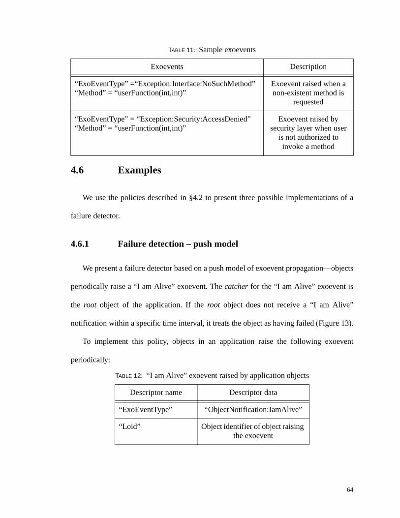
are recorded as having been sent [CHAN85, JAL94]. Figure 17 ill ustrates two processes
whose local checkpoints do not form a consistent checkpoint. Message m1 from O1 to O2
is a lost message; it is marked as having been sent in O1’s checkpoint but not as having
been received in O2’s checkpoint* . Message m2 from O1 to O2 is an orphan message; it is
recorded as being received by O2 but not as having been sent in O1’s checkpoint. Lost
messages may occur when in-transit messages between two processes are not captured by
* Note that if a checkpointing protocol runs on top of a lossy communication channel, a consistentcheckpoint may allow in-transit messages [ELNO96]. In our model, protocols run on top of areliable communication protocol.
73
a checkpointing algorithm. If O2 fails after receiving message m1 from O1 (denoted by X
on O2’s timeline) and restarts executing from its local checkpoint, m1 wil l be lost if O1
does not retransmit it. Orphan messages may occur upon restart of a process. If O1 fails
after sending message m2 (X on O1’s timeline) and restarts from its checkpoint, it would
be as if O2 had received a message that O1 had not yet sent; clearly an impossible situation
in a failure-free execution of the application.
There are two broad categories of checkpointing algorithms: uncoordinated and
coordinated checkpointing. In uncoordinated checkpointing algorithms, objects establish
local checkpoints autonomously. Uncoordinated checkpointing potentially provides lower
overhead during normal execution because objects need not coordinate checkpoints.
However, establishing a consistent application state requires non-trivial work during
recovery. Recovery algorithms for uncoordinated checkpoints must establish a consistent
set of local checkpoints to recover from [CAO92, WANG95], and deal with the possibilit y
of the domino effect [RAND75, RUSS80], where the restart of one process triggers the
rollback of other processes to avoid orphan messages. Coordinated checkpointing
algorithms avoid the domino effect by coordinating the taking of local checkpoints and
blocking interprocess communication temporarily to establish only consistent
FIGURE 17: Lost and orphan messages
(m1 ) Lost message
(m2 ) Orphan
message
O 1
O 2fail!
fail!
localcheckpoint
74
checkpoints. The primary advantage of coordinated checkpointing is its simple recovery
characteristics, albeit at the potential cost of greater overhead during normal execution.
We focus on coordinated checkpointing because of its simpler design and recovery
characteristics. We present mappings for two algorithms: SPMD checkpointing (§5.1.1)
and 2-phase commit distributed checkpointing (2PCDC) (§5.1.2). The former is named
after a style of applications known as Single Program Multiple Data applications. SPMD
applications are prevalent in parallel computing and exhibit a regular communication
structure that can be exploited to ensure consistency among checkpoints [GEIS97]. The
latter, 2PCDC, is an adaptation of an algorithm proposed by Koo and Toueg that can be
used for applications with arbitrary communication structures [KOO87].
The local state of a process should consist of all the data structures necessary to restart
that process. In computational grids, an object may be restarted on a host of a different
architecture. Thus, we do not use system-level checkpoints—core images of running
processes—because they are not portable across heterogeneous architectures. Instead, we
require that developers identify and save the relevant state. Given our object-based model
of computation, the state of an application consists of protocol-related data, user-defined
data, partial methods† and complete methods. Note that we do not include the program
counter in our state; upon restart, developers are responsible for restoring the program
counter to an appropriate point. Developers may provide programmers with tools for
automatic stack recovery [BEGU97, FERR97] or may require them to structure their code
appropriately [GEIS97].
† Recall from Chapter 3 that multiple messages may be needed to assemble a complete methodinvocation.
75
We design these algorithms to cope with permanent host failures. We assume that a
host will fail by crashing and that it may never recover. Any objects running on the
crashed host will also crash and any data contained in volatile memory is lost. We use
pings and heartbeat pulses as our failure detection mechanism.
One of the advantages of checkpointing is that once the application state is consistent
and stored on stable storage, the application can always be restarted. A checkpoint server
object serves as stable storage. Since we are interested in coping with permanent host
failure, we require that the checkpoint server be on a separate host from any of the
application objects. We assume that the checkpoint server never crashes, nor does the host
in which the application is started (as it is responsible for coordinating the checkpointing
algorithm).‡
Note that the assumptions underlying the checkpointing algorithms can be relaxed. For
example, the checkpoint server (reliable storage) could be allowed to crash given a
transient failure model in which we assume that hosts eventually recover. Furthermore, we
could tolerate network partitioning of an application if we assume that the checkpoint
server does not crash or is recoverable because an application could then be restarted from
within the partition in which the checkpoint server resides.
5.1.1 SPMD checkpointing
SPMD (Single Program Multiple Data) applications are prevalent in computational
grids [FOST94, QUIN94]. Typically, an SPMD application consists of multiple processes
that are responsible for a subdomain of the application. An SPMD application exhibits a
‡ If the coordinating host crashes, the application can still recover from the last saved consistentcheckpoint.
76
regular structure: it contains a loop that performs calculations on a subset of the data and
exchanges information periodically. Thus, it is simple to exploit the regular structure of
SPMD applications to implement application-consistent checkpointing
[GEIS97, BEGU97].
5.1.1.1 Algor ithm
To obtain a consistent checkpoint, a user inserts checkpoints in such a manner as to
guarantee that there will be no lost and no orphan messages. In general, this is a difficult
task. However, in an SPMD application, the periodic exchange of boundary information
establishes natural points for taking application consistent checkpoints, e.g., at the top or
the bottom of the main loop. The set of checkpoints at each local process defines an epoch.
By inserting a checkpoint at the top or bottom of the loop, we constrain the exchange of
messages to within an epoch, and thus guarantee no lost and no orphan messages. The
skeleton for a typical SPMD application and the insertion of a checkpoint (line 2) is shown
in Figure 18.
Recovery is relatively straightforward (Figure 19). Upon starting the application,
programmers determine whether they should restart from a previously-saved checkpoint
(lines 1-2). If so, they can call the appropriate routines to restore their state. Saving the
loop index as part of the state ensures that programmers restart from the correct iteration
FIGURE 18: Insertion of checkpoint in SPMD code
b � f N U U _ T ~ � Z U �b � f � � � � � � � � � � � � � � � � � � � � � � � � � � � � � � � � � � �b � f R X M ` O V S R w U h V ] O ^ l T V m U ^ d O Z T U V b P R V ] \ ^ R M R T Y R _ O T ^ fb � f ] U P U d R i U ^ vb � f R V ] N U U _
77
(line 5). Note that SPMD checkpointing is often hand-coded; programmers use restart files
to save application data.
5.1.1.2 Mapping SPMD checkpointing
Figure 20 ill ustrates the interface for the checkpoint server. The checkpoint server
defines methods to store and retrieve the object state and protocol-related data for each
participant. The checkpoint server also has a method, setStableCheckpoint() , to
specify that a set of checkpoints form a consistent state. When setStableCheckpoint()
is called, the checkpoint server can garbage-collect data associated with all previously
taken checkpoints. Note that the notion of consistency is not determined by the checkpoint
server but is set externally.
An application manager controls the creation of objects and is responsible for
determining when a checkpoint is consistent. During initialization, it registers to be
FIGURE 19: Recovery example
b � f � � � � � � � � � � � � � �b � f � � � � � � � � � � � � � � � � � � � � � � � � � � � � � � � � �b � f R N P R ¡ ~ �b � f N U U _ T ~ Z U �b � f � � � � � � � � � � � � � � � � � � � � � � � � � � � � � � � � � � � � � � � � � � � � � �b ¢ f R X M ` O V S R w U h V ] O ^ l T V m U ^ d O Z T U Vb £ f ] U P U d R i U ^ vb ¤ f R V ] N U U _
FIGURE 20: Interface for checkpoint server
M N O P P { ` R M v _ U T V Z c R ^ Y R ^ [R X _ U ^ Z P ¥
M N O P P ¨ _ _ N T M O Z T U V ¡ O V O S R ^ [R X _ U ^ Z P ¥
Y U T ] V U Z T m l { ` R M v _ U T V Z p O v R V b Q R S T U V W X U W Y R V Z R X U f g \ \ V U Z T m T M O Z T U V Z ` O Z M ` R M v _ U T V Z ` O P w R R V Z O v R VY U T ] V U Z T m l ª w ¦ R M Z ¨ N T Y R b Q R S T U V W X U W Y R V Z R X U f g \ \ V U Z T m T M O Z T U V U m N T Y R V R P P
_ ^ T Y O Z R ¥u � | ª T V m U g \ \ _ ^ U Z U M U N T V m U
Y U T ] P R Z r P Z O w N R b T V Z M v _ Z u a f g \ \ T V m U ^ d P Z U ^ O S R P R ^ Y R ^ M ` R M v _ U T V Z T P M U V P T P Z R V ZY U T ] P R V ] r P _ d ] r T V m U b T V Z U w ¦ u a e u � | ª T V m U f g \ \ T V T Z T O N T R _ ^ U Z U M U N T V m U
_ h w N T M ¥T V Z M ` R M v r N T Y R V R P P b f g \ \ d U V T Z U ^ ` R O N Z ` U m O _ _ N T M O Z T U VT V Z ^ R M U Y R ^ r O _ _ N T M O Z T U V b T V Z M v _ Z u a f g \ \ ^ R P Z O ^ Z O _ _ N T M O Z T U V m ^ U d M ` R M v _ U T V Z
t g
FIGURE 22: Raising the “CheckpointTaken” exoevent
Q R S T U V W X U W Y R V Z R X U gR X U ® P R Z r Z l _ R b o { ` R M v _ U T V Z p O v R V q f g \ \ P R Z Z ` R R X U R Y R V Z Z l _ RR X U ® T V P R ^ Z a R P M ^ T _ Z U ^ b o ª w ¦ u a q e ¯ d l u a f g \ \ T V P R ^ Z U w ¦ R M Z u aR X U ® T V P R ^ Z a R P M ^ T _ Z U ^ b o { v _ Z u a q e ¯ M h ^ ^ R V Z { ` R M v _ U T V Z u a f g \ \ T V P R ^ Z M ` R M v _ U T V Z u aQ R S T U V } O T P R W X U W Y R V Z b R X U f g
79
The interface for participants is shown in Figure 23 and consists of functions to save
and restore the local state, to notify the manager that a participant is alive, to notify the
manager that a checkpoint has been taken successfully and to determine whether a
participant is in recovery mode.
The application manager maintains a record of the last known live time—a timestamp
of the last successful communication—for each object. The manager updates the record
when it receives a message from an object. For example, the manager may update records
upon successfully pinging an object using check_liveness() , or upon catching the
“ I am Alive” and “CheckpointTaken” exoevents. The manager marks an object as failed if
its last known live time exceeds a user-defined threshhold. The manager then proceeds to
restart the application by killi ng and restarting each object. Once all objects have been
restarted, the coordinator informs participants that they should restart from a given
checkpoint through the call send_spmd_info() . The participants can then request the
necessary state from the checkpoint server and restart.
FIGURE 23: Interface for participants
M N O P P P _ d ] r _ O ^ Z T M T _ O V Z r d U ] h N R [R X _ U ^ Z P ¥
Y U T ] S R Z r P _ d ] r T V m U b u � | ª T V m U f g \ \ ^ R M R T Y R _ ^ U Z U M U N T V m U ^ d O Z T U V_ ^ T Y O Z R ¥
u � | ª T V m U g \ \ _ ^ U Z U M U N T V m U ^ d O Z T U VT V Z M ` R M v _ U T V Z u a g \ \ M h ^ ^ R V Z M ` R M v _ U T V Z T ]
_ h w N T M ¥Y U T ] S R Z r d U ] R b f g \ \ V U ^ d O N U ^ ^ R M U Y R ^ lY U T ] P O Y R r N U M O N r P Z O Z R b f g \ \ P O Y R P Z O Z RY U T ] ^ R P Z U ^ R r N U M O N r P Z O Z R b f g \ \ ^ R P Z U ^ R P Z O Z RY U T ] T r O d r O N T Y R b f g \ \ V U Z T m l Z ` O Z U w ¦ R M Z T P O N T Y RY U T ] M ` R M v _ U T V Z r Z O v R V b T V Z U w ¦ u a e T V Z M v _ Z u a f g \ \ V U Z T m l Z ` O Z M ` R M v _ U T V Z ` O P w R R V Z O v R V
t g
80
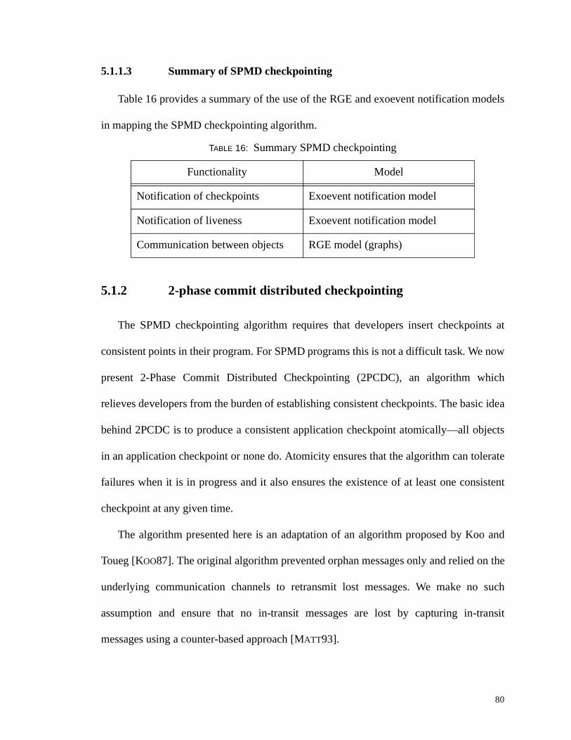
5.1.1.3 Summary of SPMD checkpointing
Table 16 provides a summary of the use of the RGE and exoevent notification models
in mapping the SPMD checkpointing algorithm.
5.1.2 2-phase commit distr ibuted checkpointing
The SPMD checkpointing algorithm requires that developers insert checkpoints at
consistent points in their program. For SPMD programs this is not a diff icult task. We now
present 2-Phase Commit Distributed Checkpointing (2PCDC), an algorithm which
relieves developers from the burden of establishing consistent checkpoints. The basic idea
behind 2PCDC is to produce a consistent application checkpoint atomically—all objects
in an application checkpoint or none do. Atomicity ensures that the algorithm can tolerate
failures when it is in progress and it also ensures the existence of at least one consistent
checkpoint at any given time.
The algorithm presented here is an adaptation of an algorithm proposed by Koo and
Toueg [KOO87]. The original algorithm prevented orphan messages only and relied on the
underlying communication channels to retransmit lost messages. We make no such
assumption and ensure that no in-transit messages are lost by capturing in-transit
messages using a counter-based approach [MATT93].
TABLE 16: Summary SPMD checkpointing
Functionality Model
Notification of checkpoints Exoevent notification model
Notification of li veness Exoevent notification model
Communication between objects RGE model (graphs)
81
5.1.2.1 Checkpointing
The algorithm proceeds in two phases (Table 17). In the first phase, the coordinator
requests that participants take a checkpoint. To reject the request, a participant sends a
“No” reply to the coordinator. Otherwise, a participant sends a “Yes” reply. Along with the
“Yes” reply, a participant also sends a counter (s,r) where s denotes the number of
messages sent and r denotes the number of messages received by the participant since its
last checkpoint. The participant then awaits the coordinator's decision.
While in the wait stage, a participant Pi may receive a message that was sent from Pj
prior to Pj taking a local checkpoint. This message is said to be in-transit and must be
recorded to prevent a lost message. Upon receipt of an in-transit message, Pi forwards the
message to the checkpoint server and informs the coordinator that it has received an in-
transit message.
TABLE 17: 2PCDC algorithm
Coordinator Participants
Requests participants take local checkpointAwait all repliesif all replies = YES then
based on message count, determine number in-transit messages if in-transit messages > 0 then
Wait till no more in-transit messagesDecide YES
else Decide NO
if accept request thenForward state to checkpoint serverReply YES & send message countAwait coordinator’s decisionif in-transit message received then
Forward message to checkpoint server and send newmessage count to coordinator
elseReply NO
Inform checkpoint server that checkpoint is consistentInform participants of decision
if decision = “YES” Reset message count
82
If and only if all participants reply “Yes” , the coordinator also decides “Yes” .
Otherwise, the coordinator decides “No”. The coordinator's authoritative decision marks
the end of the first phase. If the decision is “Yes” , the coordinator informs the checkpoint
server that the checkpoint is consistent and sends its decision to all participants.
Otherwise, the coordinator informs the checkpoint server to discard the local checkpoints
just stored.
To prevent orphan messages, a participant may not initiate communication with
another once it has taken a local checkpoint. The algorithm handles lost messages by
including a message count with each participant’s reply. To determine whether all in-
transit messages have been caught, the coordinator sums the count from each participant.
If the total number of sent messages equals the number of received messages then all i n-
transit messages have been caught and the set of local checkpoints and in-transit messages
form a consistent checkpoint.
5.1.2.2 Recovery
The recovery protocol also proceeds in two phases (Table 18). In the first phase, the
coordinator sends protocol information to each participant. The information sent informs
participants that they are in recovery mode. Each participant retrieves its state from the
checkpoint server (including in-transit messages) and informs the coordinator that it is
ready to proceed. The coordinator then awaits the ready notification from each participant.
In the second phase, the coordinator informs each participant to proceed.
We show the interface to the coordinator in Figure 24. The class INFO maintains
internal data structures required for the algorithm. As part of the initialization phase, the
coordinator sends this information to participants. The coordinator initiates the algorithm
with a call to take_2pc_checkpoint(timeout) . If any outgoing calls to the participants
do not terminate within the specified time interval, the coordinator aborts the protocol by
sending a NO decision to the participants.
TABLE 18: Recovery in 2PCDC
Coordinator Participant
Send protocol information to each participant
Await READY notification from each participants
Await protocol information from coordinator
If in recovery mode thenretrieve state from checkpoint server
Notify coordinator that participant is READY
Inform participants to start executing Await GO signal from coordinator
84
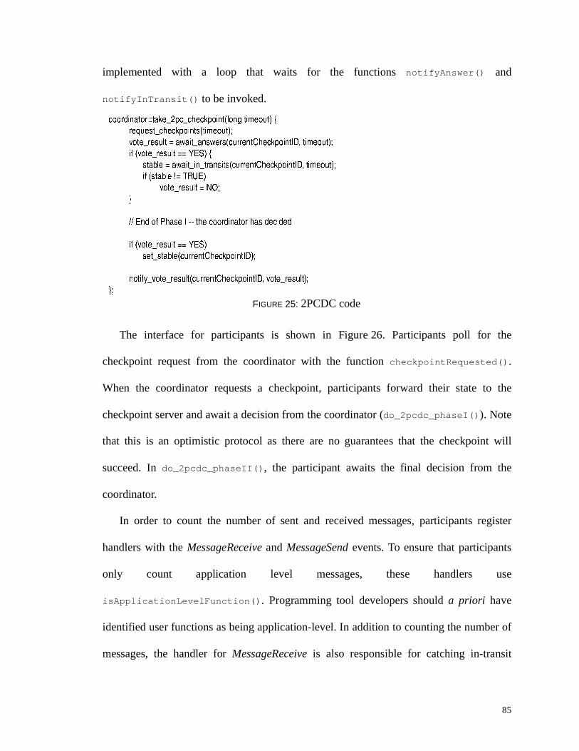
Figure 25 illustrates the implementation of take_2pc_checkpoint(timeout) . The
coordinator first requests that all participants take a checkpoint and await the participants’
answer (await_answers() ). If all participants reply “Yes” , the coordinator waits for
potential in-transit messages (await_in_transits() ). When all in-transit messages have
been caught, the coordinator commits the checkpoint (set_stable () ). Regardless of the
final outcome, the coordinator notifies participants of its decision
(notify_vote_result () ). The calls await_answers() and await_i n_transits() are
FIGURE 24: Interface for coordinator
M N O P P u � | ª [T V Z M ` R M v _ U T V Z ¨ N S U ^ T Z ` d gT V Z V h d ª w ¦ R M Z P gQ R S T U V Q ª u a N U T ] P « ¬ gT V Z U w ¦ u a gT V Z M v _ Z u a gT V Z d U ] R gQ R S T U V Q ª u a P Z U ^ O S R c R ^ Y R ^ g
t g
M N O P P M U U ^ ] T V O Z U ^ [R X _ U ^ Z P ¥
\ \ V U Z T m T M O Z T U V U m ^ R _ N l b _ ` O P R u fY U T ] V U Z T m l ¨ V P i R ^ b T V Z U w ¦ u a e T V Z M v _ Z u a e T V Z O V P i R ^ e T V Z V h d P R V Z e T V Z V h d ^ M Y ] f gY U T ] V U Z T m l u V p ^ O V P T Z b T V Z U w ¦ u a e T V Z M v _ Z u a f g \ \ V U Z T m T M O Z T U V U m T V s Z ^ O V P T Z d R P P O S RY U T ] V U Z T m l ª w ¦ R M Z ¨ N T Y R b Q R S T U V W X U W Y R V Z R X U f g \ \ V U Z T m T M O Z T U V U m N T Y R V R P P
_ ^ T Y O Z R ¥u � | ª T V m U gP R V ] r � _ M ] M r T V m U b T V Z U w ¦ u a e u � | ª T V m U f g \ \ P R V ] _ ^ U Z U M U N T V m U^ R n h R P Z r M ` R M v _ U T V Z P b T V Z M v _ Z u a f g \ \ ^ R n h R P Z P _ O ^ Z T M T _ O V Z P Z O v R M ` R M v _ U T V ZT V Z O i O T Z r _ O ^ Z T M T _ O V Z r ^ R _ N l b T V Z M v _ Z u a e N U V S Z T d R U h Z f g \ \ O i O T Z O V P i R ^T V Z O i O T Z r T V r Z ^ O V P T Z P b T V Z M v _ Z u a e N U V S Z T d R U h Z f g \ \ O i O T Z T V s Z ^ O V P T Z d R P P O S R P
Y U T ] V U Z T m l r Y U Z R r ^ R P h N Z P b T V Z M v _ Z u a e T V Z ^ R P h N Z f g \ \ P R V ] m T V O N ] R M T P T U V Z U _ O ^ Z T M T _ O V Z PY U T ] P R Z r P Z O w N R b T V Z M v _ Z u a f g \ \ T V m U ^ d M ` R M v _ U T V Z P R ^ Y R ^ M ` R M v _ U T V Z T P M U V P T P Z R V Z
_ h w N T M ¥Z O v R r � _ M r M ` R M v _ U T V Z b N U V S Z T d R U h Z f g \ \ T V T Z T O Z R � _ ` O P R O N S U ^ T Z ` d
T V Z M ` R M v r N T Y R V R P P b f g \ \ d U V T Z U ^ N T Y R V R P PT V Z ^ R M U Y R ^ r O _ _ N T M O Z T U V b T V Z M v _ Z u a f g \ \ ^ R P Z O ^ Z O _ _ N T M O Z T U V
t g
85
implemented with a loop that waits for the functions notifyAnswer ( ) and
notifyInTransit() to be invoked.
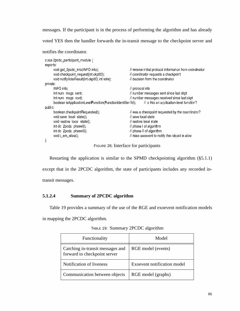
The interface for participants is shown in Figure 26. Participants poll for the
checkpoint request from the coordinator with the function chec kpointRequested() .
When the coordinator requests a checkpoint, participants forward their state to the
checkpoint server and await a decision from the coordinator (do_2pcdc_phaseI() ). Note
that this is an optimistic protocol as there are no guarantees that the checkpoint will
succeed. In do_2pcdc_phaseII() , the participant awaits the final decision from the
coordinator.
In order to count the number of sent and received messages, participants register
handlers with the MessageReceive and MessageSend events. To ensure that participants
only count application level messages, these handlers use
isApplicationLeve l Function() . Programming tool developers should a priori have
identified user functions as being application-level. In addition to counting the number of
messages, the handler for MessageReceive is also responsible for catching in-transit
FIGURE 25: 2PCDC code
M U U ^ ] T V O Z U ^ ¥ ¥ Z O v R r � _ M r M ` R M v _ U T V Z b N U V S Z T d R U h Z f [^ R n h R P Z r M ` R M v _ U T V Z P b Z T d R U h Z f g
Y U Z R r ^ R P h N Z ~ O i O T Z r O V P i R ^ P b M h ^ ^ R V Z { ` R M v _ U T V Z u a e Z T d R U h Z f gT m b Y U Z R r ^ R P h N Z ~ ~ ° W c f [
P Z O w N R ~ O i O T Z r T V r Z ^ O V P T Z P b M h ^ ^ R V Z { ` R M v _ U T V Z u a e Z T d R U h Z f gT m b P Z O w N R ± ~ p } � W f
T m b Y U Z R r ^ R P h N Z ~ ~ ° W c fP R Z r P Z O w N R b M h ^ ^ R V Z { ` R M v _ U T V Z u a f g
V U Z T m l r Y U Z R r ^ R P h N Z b M h ^ ^ R V Z { ` R M v _ U T V Z u a e Y U Z R r ^ R P h N Z f gt g
86
messages. If the participant is in the process of performing the algorithm and has already
voted YES then the handler forwards the in-transit message to the checkpoint server and
notifies the coordinator.
Restarting the application is similar to the SPMD checkpointing algorithm (§5.1.1)
except that in the 2PCDC algorithm, the state of participants includes any recorded in-
transit messages.
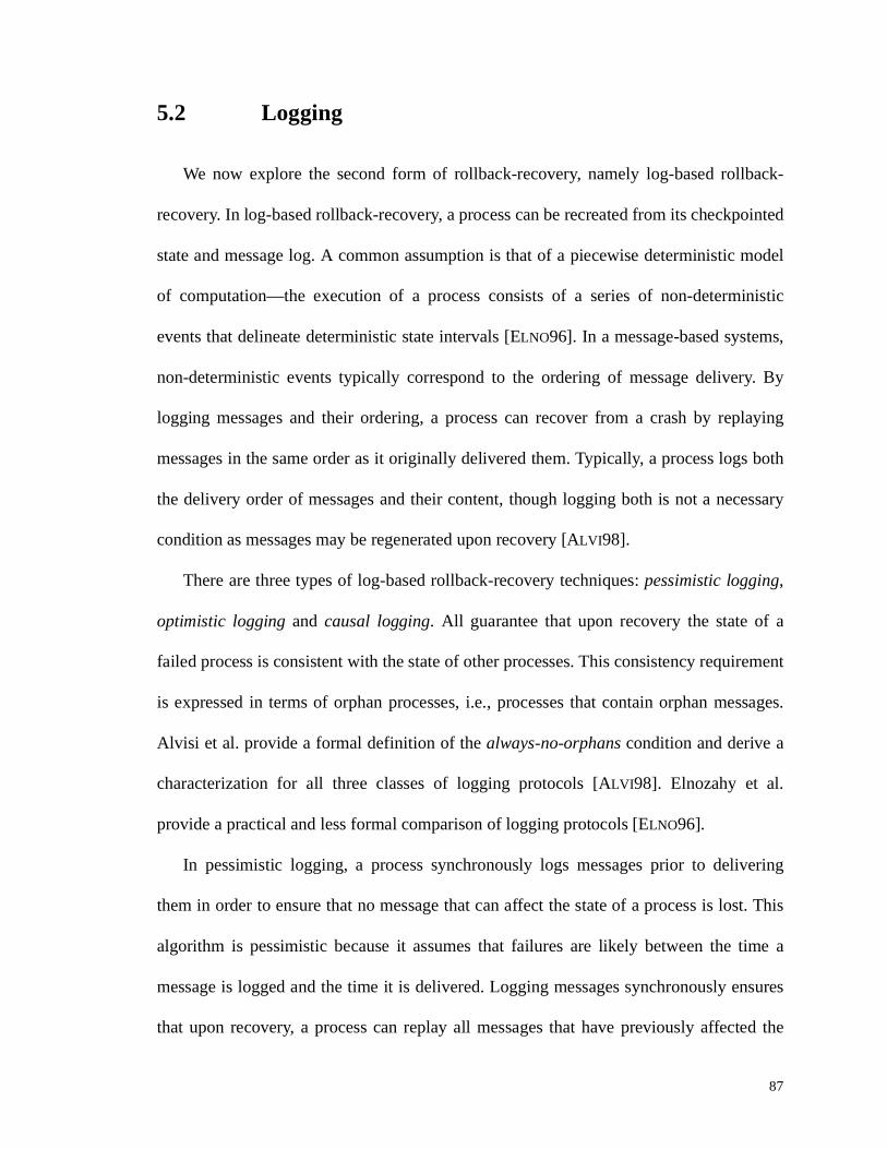
5.1.2.4 Summary of 2PCDC algor ithm
Table 19 provides a summary of the use of the RGE and exoevent notification models
in mapping the 2PCDC algorithm.
TABLE 19: Summary 2PCDC algorithm
Functionali ty Model
Catching in-transit messages and forward to checkpoint server
RGE model (events)
Notification of li veness Exoevent notification model
Communication between objects RGE model (graphs)
FIGURE 26: Interface for participants
M N O P P � _ M ] M r _ O ^ Z T M T _ O V Z r d U ] h N R [R X _ U ^ Z P ¥
Y U T ] S R Z r � _ M ] M r T V m U b u � | ª T V m U f g \ \ ^ R M R T Y R T V T Z T O N _ ^ U Z U M U N T V m U ^ d O Z T U V m ^ U d M U U ^ ] T V O Z U ^Y U T ] M ` R M v _ U T V Z r ^ R n h R P Z b T V Z M v _ Z u a f g \ \ M U U ^ ] T V O Z U ^ ^ R n h R P Z P O M ` R M v _ U T V ZY U T ] V U Z T m l ² U Z R } R P h N Z b T V Z M v _ Z u a e T V Z Y U Z R f g \ \ ] R M T P T U V m ^ U d Z ` R M U U ^ ] T V O Z U ^
_ ^ T Y O Z R ¥u � | ª T V m U g \ \ _ ^ U Z U M U N T V m UT V Z V h d r d P S P r P R V Z g \ \ V h d w R ^ d R P P O S R P P R V Z P T V M R N O P Z M v _ ZT V Z V h d r d P S P r ^ M Y ] g \ \ V h d w R ^ d R P P O S R P ^ R M R T Y R ] P T V M R N O P Z M v _ Zw U U N R O V T P ¨ _ _ N T M O Z T U V Q R Y R N | h V M Z T U V b | h V M Z T U V u ] R V Z T m T R ^ m T ] f g \ \ T P Z ` T P O V O _ _ N T M O Z T U V s N R Y R N m h V M Z T U V ³
_ h w N T M ¥w U U N R O V M ` R M v _ U T V Z } R n h R P Z R ] b f g \ \ i O P O M ` R M v _ U T V Z ^ R n h R P Z R ] w l Z ` R M U U ^ ] T V O Z U ^ ³
Y U T ] P O Y R r N U M O N r P Z O Z R b f g \ \ P O Y R N U M O N P Z O Z RY U T ] ^ R P Z U ^ R r N U M O N r P Z O Z R b f g \ \ ^ R P Z U ^ R N U M O N P Z O Z R
T V Z ] U r � _ M ] M r _ ` O P R u b f g \ \ _ ` O P R u U m O N S U ^ T Z ` dT V Z ] U r � _ M ] M r _ ` O P R u u b f g \ \ _ ` O P R u u U m O N S U ^ T Z ` d
Y U T ] T r O d r O N T Y R b f g \ \ ^ O T P R R X U R Y R V Z Z U V U Z T m l Z ` O Z U w ¦ R M Z T P O N T Y Rt g
87
5.2 Logging
We now explore the second form of rollback-recovery, namely log-based rollback-
recovery. In log-based rollback-recovery, a process can be recreated from its checkpointed
state and message log. A common assumption is that of a piecewise deterministic model
of computation—the execution of a process consists of a series of non-deterministic
events that delineate deterministic state intervals [ELNO96]. In a message-based systems,
non-deterministic events typically correspond to the ordering of message delivery. By
logging messages and their ordering, a process can recover from a crash by replaying
messages in the same order as it originally delivered them. Typically, a process logs both
the delivery order of messages and their content, though logging both is not a necessary
condition as messages may be regenerated upon recovery [ALVI98].
There are three types of log-based rollback-recovery techniques: pessimistic logging,
optimistic logging and causal logging. All guarantee that upon recovery the state of a
failed process is consistent with the state of other processes. This consistency requirement
is expressed in terms of orphan processes, i.e., processes that contain orphan messages.
Alvisi et al. provide a formal definition of the always-no-orphans condition and derive a
characterization for all three classes of logging protocols [ALVI98]. Elnozahy et al.
provide a practical and less formal comparison of logging protocols [ELNO96].
In pessimistic logging, a process synchronously logs messages prior to delivering
them in order to ensure that no message that can affect the state of a process is lost. This
algorithm is pessimistic because it assumes that failures are likely between the time a
message is logged and the time it is delivered. Logging messages synchronously ensures
that upon recovery, a process can replay all messages that have previously affected the
88
state. The advantage of this technique is that recovery is simple and localized: a process
recovers by retrieving its last checkpoint and replaying its message log. It does not need to
coordinate recovery with other processes in the application. The drawback of pessimistic
logging is the high failure-free overhead of logging messages synchronously.
In contrast, optimistic logging protocols log messages asynchronously. The implicit
assumption is that failure is unlikely to occur between the time a message is logged and
the time it is delivered. A process does not block to perform the logging of messages; thus
the potential for higher failure-free performance. The problem is that sometimes an
optimistic assumption can be wrong. If a process crashes before a message has been
logged, information such as message delivery order or message content will be lost. To
compound the problem, if the crashed process has sent messages to other processes (and
potentially affected their state), these processes wil l become orphans and must be rolled
back during recovery. Thus, optimistic protocols require tracking dependencies during a
failure-free run to support a consistent recovery. Furthermore, processes in an optimistic
protocol may be required to rollback to a previous checkpoint whereas rollback for
pessimistic protocols is bounded to the last checkpoint.
Causal logging techniques strike a balance between pessimistic and optimistic
protocols. They do not require blocking during a failure-free run nor do they create orphan
processes. Causal logging maintain information about events that have a causal effect on
the state of processes [ELNO92, ALVI93]. This information can be used to reestablish the
delivery order of messages upon recovery and limit the extent of rollbacks to the last
saved checkpoint. Causal logging techniques do not suffer a high failure-free performance
cost as they do not synchronously log messages to stable storage. Furthermore, causal
89
logging bounds the rollback of any failed process to its last checkpoint. As with optimistic
logging, the drawback of causal logging is its complex recovery protocols.
For a detailed analysis of the similarities and differences between logging protocols
please see the literature [ALVI98]. There are other issues related to logging that we have
not discussed, e.g., interactions with the outside world, asynchronous vs. synchronous
recovery and garbage collection. For a treatment of these issues, please see the survey by
Elnozahy [ELNO96].
For the purpose of mapping algorithms to the RGE and exoevent notification models,
we focus on pessismistic logging because of its simplicity and the fact that, despite its high
overhead, most commercial implementations of message logging use pessimistic logging
[HUAN95]. Similarly to the work in Ho’s master’s thesis, we adapt a pessimistic message
logging protocol to an object-based system [HO99].
We design our system to tolerate a single permanent host failure. We use a checkpoint
server object as stable storage for storing checkpoints and message logs. Thus, the
algorithm can tolerate either the failure of the server or of the checkpoint server, but not
both. We further assume that no network partitioning occurs.
5.2.1 Pessimistic message logging
We have discussed the piecewise deterministic model in terms of processes and
messages. In an object-based system, the non-deterministic events of interest are the order
in which methods are delivered. By logging the delivery of methods, we can recreate the
execution of an object by replaying its methods. We implement the logging of methods by
logging messages.
90
Pessimistic message logging (PML) enables the abstraction of a resili ent object, an
object that can mask failures. Object failure is masked by the PML protocol; other objects
should only see a pause while PML recovers an object. We implement PML by logging
messages onto stable storage. An advantage of PML is the ability to recover an object
locally, without needing to coordinate recovery with other application objects. However,
the simple recovery characteristic of PML comes at the cost of logging messages during
normal execution.
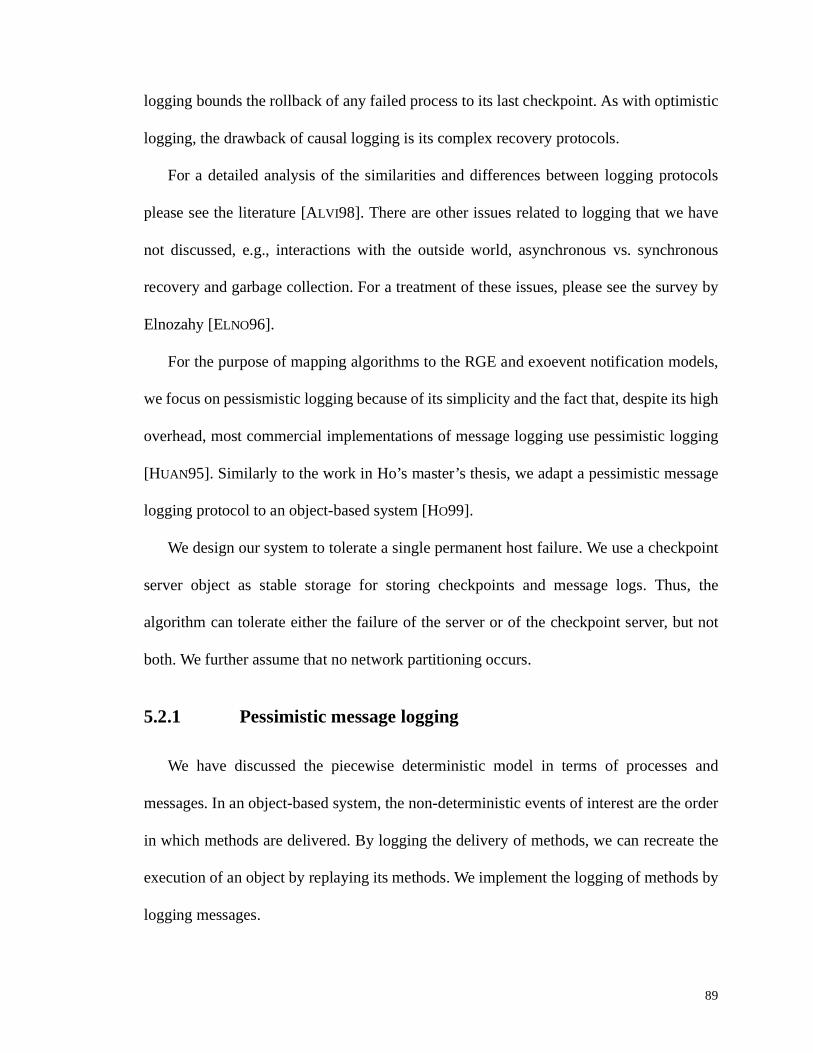
In Figure27 we show a client invoking the method foo on object A (1). For this
example, we assume that a single message is suff icient to form a complete method
invocation for foo . Upon receipt of the message from the client, the PML module sends the
message to the CheckpointServer object (2). Once PML receives an acknowledgement
from CheckpointServer that the message has been stored successfully (3), PML allows the
message to flow to the MethodAssembly module (4). Since the message forms a
complete method, A can execute the method foo (5). Object A then returns the reply to the
client (6).
In order to recover an object, we restart it from its last checkpoint, retrieve the
message log, and replay messages in their original order. While replaying the message log,
we intercept outgoing messages in order to prevent sending duplicate messages. If object
A received a reply during its original execution, e.g., as a result of making a method
invocation on other objects, we retrieve the reply from the log. Once all messages have
been replayed, we let outgoing messages proceed normally at which point we have
recovered the object successfully.
91
Clients that expect a reply should see a pause while a recovery protocol is in progress.
In practice, clients should retry an invocation after a certain amount of time in case an
object fails before logging a message. The implication of the possibility of retries is that
objects should handle duplicate method invocations.
5.2.2 Mapping pessimistic message logging
Figure 28 shows the interface to the module for implementing pessimistic message
logging. To intercept messages we register the handler LogMessageHandler with the
event MessageReceive. Inside the handler, we forward the message to the checkpoint
server and await acknowledgement that the message has been stored successfully. To store
FIGURE 27: Pessimistic message logging (PML)
Pessimist ic MessageLogg ing
MethodAssembly
PML
(1) A.foo()
(5)service method
(2) send message
(3) message OK
foo()
bar()
Client
(4)(6) reply
CheckpointServer
92
return values, we register the handler MethodStartHandler with the MethodReady event
and the handler StoreRetainedResultHandler with the MethodDone event.
Inside MethodStartHandle r , we insert the computation tag of the method in an
associative array that maps computation tags to return values. Since the method is about to
start executing, the tag maps to an empty value. When the method finishes executing and
StoreRetainedResu l tHandler is invoked, we update the associative array to store the
returned values, and forward the returned values to the CheckpointServer object. The code
P R Z { ` R M v _ U T V Z c R ^ Y R ^ b Q ª u a f g \ \ P R Z M ` R M v _ U T V Z P R ^ Y R ^_ ^ T Y O Z R ¥
Q ª u a { ` R M v _ U T V Z c R ^ Y R ^ g \ \ V O d R U m M ` R M v _ U T V Z P R ^ Y R ^j p ¨ z e } W c � Q p c k ^ R Z O T V R ] } R P h N Z P g \ \ v R R _ Z ^ O M v U m T V Y U v R ] d R Z ` U ] P O V ] ^ R _ N T R PT V Z Q U S ¡ R P P O S R b ¡ W c c ¨ z W f g \ \ N U S d R P P O S R Z U M ` R M v _ U T V Z P R ^ Y R ^T V Z Q U S } R Z O T V R ] } R P h N Z P b } W c � Q p c f g \ \ N U S ^ R Z h ^ V Y O N h R P Z U M ` R M v _ U T V Z P R ^ Y R ^T V Z } R M U Y R ^ Q U S P b ¡ W c c ¨ z W e } W c � Q p c f g \ \ ^ R M U Y R ^ O N N N U S P
_ h w N T M ¥T V Z Q U S ¡ R P P O S R y O V ] N R ^ b W Y R V Z f g \ \ ` O V ] N R ^ T V Y U v R ] h _ U V ^ R M R T _ Z U m O d R P P O S RT V Z ¡ R Z ` U ] c Z O ^ Z y O V ] N R ^ b W Y R V Z f g \ \ ` O V ] N R ^ T V Y U v R ] i ` R V O d R Z ` U ] T P O w U h Z Z U R X R M h Z RT V Z c Z U ^ R } R Z O T V R ] } R P h N Z y O V ] N R ^ b W Y R V Z f g \ \ ` O V ] N R ^ m U ^ i ` R V d R Z ` U ] m T V T P ` R P R X R M h Z T V ST V Z u V Z R ^ M R _ Z ª h Z S U T V S ¡ R P P O S R P b W Y R V Z f g \ \ ` O V ] N R ^ Z U P Z U _ U h Z S U T V S d P S P ] h ^ T V S ^ R M U Y R ^ l
t
FIGURE 28: Interface for pessimistic message logging
93
To recover, an object retrieves its last saved checkpoint and all l ogs from the
CheckpointServer. Next, it replays each message in order to recreate the original execution
of the object. We trap outgoing communications so that other objects do not receive
duplicate requests (Figure30). Whenever an object is blocked waiting on a return value
from some other object, the result values can be found in the message log. Once all
messages have been replayed and all return values extracted, an object stops intercepting
outgoing method invocations, and the object resumes normal processing.
} W c � Q p c ^ R P h N Z P ~ i ® S R Z } R P h N Z P b f g^ R Z O T V R ] } R P h N Z P ® T V P R ^ Z b Z e ^ R P h N Z P f g^ R Z h ^ V W Y R V Z { U V Z T V h R g
tFIGURE 29: Handlers for pessimistic message logging
94
5.2.3 Optimization: pessimistic method logging
We present an optimization to pessimistic message logging that relies on the following
two assumptions: (1) an object receives complete method invocations only, i.e., all its
arguments are contained in a single message, and (2) an object does not call other objects
while servicing a request. Based on these assumptions, we modify the pessimistic message
logging algorithm to pessimistic method logging.
The differences between pessimistic method logging and pessimistic message logging
are that instead of forwarding messages to the checkpoint server, we forward complete
method invocations; and instead of replaying messages during recovery, we replay
methods. In Figure31, we show a client invoking A.foo() (1). Instead of logging
messages as in §5.2.2, we log methods (2). Forwarding complete method invocations to
the checkpoint server (3-4) is implemented by registering a handler with the MethodReady
event. The handler assembles and executes a graph to store the method invocation at the
checkpoint server. Once the checkpoint server has acknowledged receipt of the method, A
i ~ b ´ ª } µ r } W ¶ � W c p f R Y ® S R Z a O Z O b f gd ~ i s k S R Z ¡ R Z ` U ] b f gT m b T P c Z O Z R � _ ] O Z T V S b d f f [
§ � | | W } P Z O Z R ~ P O Y R � P R ^ c Z O Z R b f gP h M M R P P ~ P R V ] c Z O Z R p U § O M v h _ b P Z O Z R e Z T d R U h Z f gT m b P h M M R P P f ^ R Z h ^ V { U V Z T V h R y O V ] N R W Y R V Z gR N P R [
^ R M U V m T S h ^ R § O M v h _ b f gP h M M R P P ~ P R V ] c Z O Z R p U § O M v h _ b P Z O Z R e Z T d R U h Z f gT m b P h M M R P P f ^ R Z h ^ V { U V Z T V h R y O V ] N R W Y R V Z gR N P R ^ O T P R W X M R _ Z T U V b o W } } ª } q f g
tt^ R Z h ^ V { U V Z T V h R y O V ] N R W Y R V Z g
´ ª } µ r } W ¶ � W c p i gi ~ b ¡ W p y ª a f R Y ® S R Z a O Z O b f g
c W � a r } W c � Q p c b i f g^ R Z h ^ V { U V Z T V h R y O V ] N R W Y R V Z g
tFIGURE 34: Handlers for passive replication (primary)
102
Figure 35 illustrates the process of invoking a method foo on object S. A client object
first contacts the class of S to obtain a binding for S (1). The binding contains an object
address, i.e., a low-level name, with which to communicate with S (2). Normally, the
binding returned by Class S corresponds to the primary object (3). However, if the primary
object crashes, Class S initiates a failover protocol that consists of making the backup the
new primary object. On subsequent binding requests, Class S returns a binding that
corresponds to the new primary object.
5.3.1.3 Summary of passive replication
Table 21 provides a summary of the use of the RGE and exoevent notification models
in mapping the passive replication algorithm.
TABLE 21: Summary of the passive replication algorithm
Functionali ty Model
Updating state of backup when a method finishes execution
RGE model (graphs & events)
Raising exceptions Exoevent notification model
Detection of duplicate methods RGE model (events)
FIGURE 35: Server lookup with primary replication
S
Client
Class S
Primary
Backup
(1) lookup(LOID(S))
(2) binding(3) S.foo()
103
5.3.2 Stateless replication
Stateless objects—objects whose methods are side-effect free—can be replicated to
provide higher performance [GRIM96A], higher availabilit y, or both [BABA92, CASA97,
NGUY95, NGUY96]. Stateless objects are used in several applications, including file
servers, mathematical li braries, graphical rendering, biochemistry, and pipe and filter
applications. The original stateless replication was designed to achieve higher
performance through the load-balancing of parallel requests on stateless objects. The
problem was that the failure of any replicas would lead to the failure of the application that
uses stateless objects. We modified the algorithm to tolerate failures of replicas through a
retry mechanism.
We present stateless replication, an algorithm for managing stateless replicas. The
architecture of this algorithm is shown in Figure 36. Note the presence of a proxy object
that intercepts method calls intended for the replicas. The algorithm tolerates the crash
failures of replicas. We assume that the proxy object never crashes and that the network is
reliable. However, the assumption of a reliable network could be relaxed. If the network
partitions, workers that are outside of the primary partition can be treated as having failed.
The proxy object would reassign the failed computation to workers that reside within the
primary partition.
When the proxy object receives a work request, i.e., a method call i ntended for the
replicas, it stores the request in an internal queue. The proxy object maintains a capacity
State transfer Provided by developer
TABLE 21: Summary of the passive replication algorithm
Functionali ty Model
104
count for its replicas, i.e., the maximum number of work requests that can be issued at any
given time. The proxy dequeues work requests and selects replicas for performing the
work until the maximum capacity is reached.
The selection algorithm can be a simple one such as random or round-robin, or it can
be a more complex algorithm such as least-loaded. When a replica finishes a method
invocation, it notifies the proxy (dashed arrow labeled “done” in Figure36). This
notification is the basis for monitoring the progress of an invocation; if a method that has
been assigned to a replica fails to finish executing within a specified time interval, the
proxy can reassign the work to another replica. Furthermore, the arrival of the notification
triggers the assignment of another work request to a replica. Thus, this architectures
achieves a form of self-scheduling, replicas that execute fastest, whether because they are
inherently faster or servicing less computationally demanding methods, receive on
average more work from the proxy. Note that other replication algorithms could be
implemented. For example, a form of active replication could be implemented by having
the proxy schedule N duplicates for each work request [NGUY95].
Relying on a timeout value for reassigning work requests may lead to multiple results
being sent back to clients. Thus, clients must be able to handle the possibilit y of duplicate
FIGURE 36: Stateless replication
Replicas
O 1
O 2
O n
ProxyClient O.foo()
done
reply
Method
105
replies. In environments in which client objects are waiting on a specific reply, this task is
easy. In others, duplicates should be detected and discarded (§5.3.2.2).
5.3.2.1 Mapping stateless replication
The proxy object implements the stateless replication algorithm. The proxy object
exports methods for registering and unregistering replicas, setting the queue capacity, and
specifying a time interval after which to reassign work requests (Figure 37).
We register the handler methodInvokeHandler with the MethodReady event. Inside
methodInvokeHandl er we determine whether the method is intended for the proxy object
itself or for the replicated object. If it is intended for the proxy object, we route it to the
appropriate function and update various data structures such as the list of candidate
FIGURE 37: Interface for proxy object
M N O P P ´ ª } µ r } W ¶ � W c p [¡ W p y ª a d R Z ` U ] g \ \ m h V M Z T U V P T S V O Z h ^ R e O ^ S h d R V Z P e M U d _ h Z O Z T U V Z O SN U V S Z T d R } R M R T Y R ] g \ \ Z T d R i U ^ v ^ R n h R P Z ^ R M R T Y R ]N U V S Z T d R c Z O ^ Z R ] g \ \ Z T d R i U ^ v ^ R n h R P Z P R V Z Z U ^ R _ N T M ON U V S Z T d R W V ] R ] g \ \ Z T d R i U ^ v ^ R n h R P Z ] U V RT V Z V h d p ^ T R P g \ \ ` U i d O V l Z T d R P ` O Y R i R Z ^ T R ] Z ` T P i U ^ v ^ R n h R P ZT V Z ^ R Z ^ l O w N R g \ \ P ` U h N ] i R ^ R Z ^ l Z ` T P i U ^ v ^ R n h R P Z T m T Z ] U R P V x Z
\ \ m T V T P ` R X R M h Z T V S T V O Z T d R N l d O V V R ^ ³t g
Y U T ] V U Z T m l ¡ R Z ` U ] a U V R b Q R S T U V W X U W Y R V Z f g \ \ V U Z T m T M O Z T U V Z ` O Z ^ R _ N T M O ` O P m T V T P ` R ] R X R M h Z T V S Od R Z ` U ]
Y U T ] ¦ U T V b Q ª u a f g \ \ O ] ] ^ R _ N T M O Z U Z ` R _ U U NY U T ] N R O Y R b Q ª u a f g \ \ ^ R d U Y R ^ R _ N T M O m ^ U d Z ` R _ U U NY U T ] P R Z p T d R U h Z b N U V S Z T d R U h Z f g \ \ P R Z Z T d R U h Z Y O N h R O m Z R ^ i ` T M ` Z U ^ R O P P T S V i U ^ vY U T ] P R Z { O _ O M T Z l b T V Z f g \ \ P R Z Z ` R n h R h R M O _ O M T Z l
_ ^ T Y O Z R ¥w U U N R O V T P } R _ N T M O | h V M Z T U V b | h V M Z T U V u ] R V Z T m T R ^ m T ] f g \ \ h P R ] Z U ] R Z R ^ d T V R i ` R Z ` R ^ M O N N T P m U ^ _ ^ U X l U ^ ^ R _ N T M O
y ¨ � a Q W } d R Z ` U ] u V Y U v R y O V ] N R ^ g \ \ ` O V ] N R ^ m U ^ M O Z M ` T V S ¡ R Z ` U ] } R O ] l R Y R V Z PQ ª u a ^ R _ N T M O P « ¬ g \ \ N T P Z U m ^ R _ N T M O P
_ h w N T M ¥` O V ] N R ¡ R Z ` U ] u V Y U M O Z T U V b ´ ª } µ r } W ¶ � W c p f g \ \ ` O V ] N R O V T V M U d T V S d R Z ` U ] T V Y U M O Z T U V
t g
106
replicas. If it is intended for the replicated object, we store the method in a queue of work
requests. The work request contains the method, its arguments, and other information such
as timestamps.
Provided there is spare capacity, the proxy dequeues work requests, sends them to the
replicas, and stores them in the in_progress queue (Figure 38).
Upon finishing a method invocation, replicas raise the exoevent
“Object:MethodDone”. Descriptors for the exoevent contain the function signature and its
computation tag. To be notified of this exoevent, the proxy object sets an exoevent interest
to catch “Object:MethodDone” exoevents (Table 22):
TABLE 22: “Object:MethodDone” notification by replica
Exoevent interest
categoryString “Object:MethodDone”
\ \ M U ] R Z U P R V ] i U ^ v ^ R n h R P Z Z U ^ R _ N T M OT V Y U v R r ^ R _ N T M O r m h V M Z T U V b ´ ª } µ r } W ¶ � W c p i f [
W Y R V Z R Y ~ V R i W Y R V Z b ¡ R Z ` U ] c R V ] f g \ \ M ^ R O Z R O ¡ R Z ` U ] c R V ] R Y R V Z¡ W p y ª a d ~ i s k S R Z ¡ R Z ` U ] b f g \ \ S R Z Z ` R d R Z ` U ] ] O Z O P Z ^ h M Z h ^ RR Y s k P R Z a O Z O b d f g \ \ P R Z ] O Z O m T R N ] U m R Y R V ZW Y R V Z ¡ O V O S R ^ ® O V V U h V M R b R Y f g \ \ ^ O T P R R Y R V Z
t
Y U T ] ` O V ] N R ¡ R Z ` U ] u V Y U M O Z T U V b ´ ª } µ r } W ¶ � W c p i U ^ v f [T m b V U Z T P } R _ N T M O Z T U V | h V M Z T U V b i U ^ v ® m T ] f f [
replication and stateless replication. Table 24 summarizes the faults tolerated by these
algorithms and their assumptions. Note that for the checkpointing algorithms we have
assumed that the host that starts the application (the checkpoint coordinator) does not
crash. If the coordinator crashes, the application can still be restarted from the saved
checkpoints.
Detecting duplicate return values RGE model (events)
Raising exceptions Exoevent notification model
Failure detection RGE model (events)
Table 24: Summary of algorithms
Algorithm
Number of worker failures tolerated
Assumptions Comments
SPMD checkpointing
n • reliable store• reliable network• checkpoint coordinator does not crash
reliable network assumption can be relaxed
2PCDC checkpointing
n • reliable store• reliable network• checkpoint coordinator does not crash
reliable network assumption can be relaxed
Table 23: Summary of the passive replication algorithm
Functionali ty Model
110
The implementation of pessimistic method logging and passive replication required
system support to change the behavior of object creation or other object-management
services. In the next chapter, we show the incorporation of fault-tolerance algorithms in
programming tools and the API that developers present to programmers.
Pessimistic method logging
1 • reliable store• reliable network
none
Passive replication
1 • reliable network the backup is represented by an object that is allowed to crash
Stateless replication
n-1 • reliable store• reliable network
reliable network assumption can be relaxed
Table 24: Summary of algorithms
Algorithm
Number of worker failures tolerated
Assumptions Comments
111
Obstacles are those frightful things you seewhen you take your eyes off your goal.
— Henry Ford
Chapter 6
Integration into Programming Tools
We present the integration of the fault-tolerance algorithms presented in Chapter 5 into
the following programming tools: the Message Passing Interface (MPI), the de facto
message passing standard in the grid community [GROP99]; the Stub Generator, a tool for
writing client/server applications; and the Mentat Programming Language (MPL), an
object-based parallel processing language. We describe the integration of fault-tolerance
algorithms into these environments and describe the interface presented to application
programmers.
We show that the burden placed on application programmers is manageable, ranging
from inserting a few extra lines of code, writing routines to save and restore state, to
setting command-line options. For tool developers, incorporating the fault-tolerance
algorithms requires targeting the RGE and exoevent notification models and linking in the
proper fault-tolerance libraries.
We present the integration of the SPMD and 2PCDC checkpointing techniques into the
MPI environment (§6.1). For the Stub Generator, we present the integration of passive
112
replication and pessimistic method logging (§6.2). For MPL, we present the integration of
stateless replication (§6.3). For each environment, we present a high-level overview so
that readers may compare the interface to programmers both before and after the
integration of fault-tolerance algorithms.
All three environments use the reflective graph and event model and the exoevent
notification model and have been deployed for over 2 years. The algorithms have been
tested using synthetic test cases designed to stress various parts of the algorithms, e.g.,
ensuring that invariants hold, that the output of a program after recovery is correct, as well
as using several real-world applications (Chapter 7).
6.1 MPI (SPMD and 2PCDC Checkpointing)
The Message Passing Interface (MPI) is a message-passing standard that is used
widely on parallel machines and networks of workstations to develop parallel and
distributed applications [GROP99]. The goals of the MPI designers were to achieve
portabilit y, flexibil ity and ease-of use through the specification of a standard application
programmer interface based on the familiar message passing paradigm. MPI is supported
by all major computer manufacturers.
Our goal in augmenting the Legion MPI implementation (LMPI) is to provide MPI
programmers with a simple interface for supporting application checkpoint/restart. We
add only six new functions and refer to our augmented implementation as LMPI-FT. We
present a brief overview of MPI by describing several of its most commonly-used
functions and show an example program (§6.1.1). Next, we describe the architecture and
interface of LMPI-FT (§6.1.2) and ill ustrate its use with a simple program (§6.1.3). We
113
conclude this subsection by summarizing the efforts required from both developers and
programmers (§6.1.4).
6.1.1 Legion MPI (LMPI)
Table 25 shows six of the most commonly used MPI functions [FOST94].
TABLE 25: Sample MPI functions
MPI functions Description
mpi_init() Initiate an MPI computation
mpi_finalize() Terminate a computation
mpi_comm_size(comm, size)comm – communicator size – # of tasks inside of communicator
Determine number of tasks
mpi_comm_rank(comm, rank)comm – communicator rank – id within communicator
Determine my task identifier
mpi_send(buf, count, datatype, target, tag, comm)buf – address of buffercount – # of items to receivedatatype – type of the itemstarget – rank id of the target tasktag – id of the messagecomm – communicator used
Blocking send of message
mpi_recv(buf, count, datatype, source, tag, comm, status)buf – address of buffercount – # of items to receivedatatype – type of the itemssource – rank id of the source tasktag – id of the messagecomm – communicator usedstatus – status/error values
Blocking receive of message
114
Note that MPI uses the concept of a communicator to group related tasks. A global
communicator, MPI_COMM_WORLD, groups all tasks in an application. For more
information about communicators and other communication primitives, please refer to the
MPI standard [GROP99].
An MPI application typically consists of a fixed number of tasks (or processes) that
are started from the command-line. For example, in Legion MPI (LMPI), an application is
started with the command-line utilit y legion_mpi_ r un that takes as arguments the
number of tasks to be created and the name of the program, e.g., legion_mpi_run -n
4 myprogram .
Figure 39 shows a simple MPI program. MPI tasks are logically organized in a ring
and are denoted as task0..n-1. At each iteration a task sends an integer to its left neighbor
115
and receives an integer from its right neighbor (lines 14-25). Note that the left neighbor of
task0 is taskn-1 and the right neighbor of taskn-1 is task0.
Running this program with the command legion_mpi_run -n 4 myprogram
yields the output:
I am task 0 and I have received the value 0 from my neighbor
I am task 1 and I have received the value 0 from my neighbor
I am task 2 and I have received the value 0 from my neighbor
I am task 3 and I have received the value 0 from my neighbor
I am task 0 and I have received the value 1 from my neighbor
...
6.1.2 Legion MPI-FT
Our extensions to LMPI provide programmers with optional functionalit ies. MPI
programmers are exposed only to the additional functions defined by LMPI-FT when they
need to use the checkpoint/restart faciliti es. The relationship between programmers,
LMPI-FT, and the RGE and exoevent notification models is shown in Figure 40.
LMPI-FT exports the standard MPI interface to programmers as well as several new
functions to support checkpoint/restart (Table 26). The internal implementation of the
standard MPI interface targets the RGE and exoevent notification models. Calls such as
mpi_send() and mpi_recv() are implemented by raising events and executing
graphs. Similarly, the FT modules also target the models, thus enabling the composition of
the checkpointing algorithms within LMPI-FT.
To support checkpointing, application programmers insert code to save and restore
state. Table 26 describes the extensions to MPI to support checkpoint and restart.
TABLE 26: Functions to support checkpoint/restart
LMPI-FT functions Description
int mpi_ft_on() Returns:0 – no checkpointing specified1 – SPMD checkpointing2 – 2PCDC checkpointing
mpi_ft_init(int rank, int &recovery) Initiate the checkpoint/recovery libraryRank is the id of the MPI task<recovery> is true if in recovery mode
FIGURE 40: Legion MPI architecture augmented with FT modules
MPI implementation (LMPI-FT)
RGE & Exoevent Notification Models
Graphs, events, exoevents
MPI Programmers
FT ModuleSPMD and 2PCDCCheckpointing
117
Furthermore, we add several flags to legio n_mpi_run to specify parameters for
the checkpoint and restart algorithms (Table 27):
For example, the command,
legion_mpi_run -n 2 -ft -spmd -s myCheckpoin t Server -g 200
-r 500 myapp ,
mpi_ft_save(char *buffer, int size) Save data onto storage
mpi_ft_save_done(); Done saving data for this checkpoint
mpi_ft_restore(char *buffer, int size) Restore data from storage
int mpi_ft_checkpoint_request(int &ckptid) Returns true if a checkpoint has been requested by the coordinator. Also sets the checkpoint id (only used with 2PCDC checkpointing)
TABLE 27: Options for legion_mpi_run
Options Descriptions
-ft [-spmd | -2pc <ckptFreq>] Specify either SPMD or 2PCDC checkpointing. If 2PCDC checkpointing, <ckptFreq> specifies how often to request a checkpoint.
-s <checkpoint server> Specify the checkpoint server from which checkpoints will be stored and retrieved. This option may be repeated to specify multiple checkpoint servers.
-g <ping interval> Specify the ping frequency for each MPI task
-r <reconfigurationTime> If we have not heard from an MPI task in the last <reconfigurationTime> seconds, restart the application from the last consistent checkpoint.
-R Specifies recovery mode. Restart application from the last consistent checkpoint.
TABLE 26: Functions to support checkpoint/restart
LMPI-FT functions Description
118
specifies that the application should run with 2 tasks, that it uses the checkpoint server
called myCheckpointServe r , that the ping interval is 200 seconds and that the
reconfiguration time is 500 seconds. We provide a command-line tool,
legion_create_ checkpoint_server <name> , to create a checkpoint server.
6.1.3 Example
We illustrate the use of the checkpointing library for the SPMD and 2PCDC
algorithms using the same example MPI program as above (Figure 41). This toy
application is representative of SPMD programs and il lustrates the amount of work
required from programmers.
The code required to support checkpointing is shown italicized in Figure 41. This code
consists of functions to set up the checkpointing libraries (lines 9-10) and functions to call
the checkpointing routines (lines 11, 15-24). Where to insert code to take a checkpoint
depends on the algorithm used. For SPMD checkpointing, the programmer is responsible
for specifying when to checkpoint, e.g., every tenth iteration (lines 16-20, 23-24). For
2PCDC checkpointing, the participant periodically polls to determine whether a
checkpoint has been requested by the coordinator, i.e., legion_mpi_run (lines 19-24).
119
Upon recovery, the programmer is responsible for restarting the program from an
appropriate point in the code. In this example, the programmer can restart from the proper
loop index because the loop index is saved when taking a checkpoint.
FIGURE 41: Example of MPI application with checkpointing
¿ À Á  à Ŀ Å Á Æ Ç Â Ã ¿ Â Ã Ä Ç È É Ê Ë Ê Ì Ç È Í Í Ç È É Î Á¿ Ï Á п Ñ Á Ò Ò Î Ç È Â Ç Ó Ô Õ Ö Õ Ê Ô Ç È Ç Ä Â × Ã × Æ Æ Â Ä Ä Õ Ö¿ Ø Á Ù Ú Û Ü Û Ã Â Ä ¿ Ý Ç È É Ê Ë Ý Ç È É Î Á Þ¿ ß Á Ù Ú Û Ü à × Æ Æ Ü È Ç Ã á ¿ Ù Ú Û Ü à â Ù Ù Ü ã â ä å æ Ë Ý Æ ç Â Ö Á Þ¿ è Á Ù Ú Û Ü à × Æ Æ Ü é  ê Õ ¿ Ù Ú Û Ü à â Ù Ù Ü ã â ä å æ Ë Ý Ã ë Æ Ü Ä Ç é á é Á Þ¿ ì Áí î ï ð ñ ò ó ô ñ ð õ ö ÷ ø ù ú û ü ú ù ý þ ÿ í � õ þ � ï �í � � ï � � � ó ð þ ÿ � � ö ÷ ø ù ú û ü ú ý í ï �í � � ï þ í ð ñ ò ó ô ñ ð õ ï ð ñ � ÿ ó ð ñ ú � ÿ � ÿ ñ í � � ÿ � ð ÿ ú þ ÿ ñ ð � ÿ þ ó ý ïí � ï ñ � � ñ � ÿ � ð ÿ ú þ ÿ ñ ð � ÿ þ ó ý ö � �¿ À Ï Á¿ À Ñ Á � × È ¿ Â Ä Õ È Ç Ä Â × Ã � é Ä Ç È Ä Ü Â Ä Õ È Ç Ä Â × Ã Þ Â Ä Õ È Ç Ä Â × Ã � � � Ù Ü Û � � ä � � Û â � � Þ � � Â Ä Õ È Ç Ä Â × Ã Á Ðí � � ï þ ý ÿ ÿ � � ñ ú ò � ñ ò � � ó þ ý ÿ ö û � � � �í � � ï þ í � � � ó ð þ ÿ � � ö ö � ø ÷ ï !í � " ï þ í þ ÿ ñ ð � ÿ þ ó ý # � � ö ö � � � þ ÿ ñ ð � ÿ þ ó ý $ � ïí � % ï ÿ � � ñ ú ò � ñ ò � � ó þ ý ÿ ö ü & ' � �í � î ï ( ñ � � ñ ! ) ) � � � ó ð þ ÿ � � þ � ø * *í � ï þ í � � þ ú ÿ ú ò � ñ ò � � ó þ ý ÿ ú ð ñ + , ñ � ÿ í ï ïí � ï ÿ � � ñ ú ò � ñ ò � � ó þ ý ÿ ö ü & ' � �í ï (í - ï þ í ÿ � � ñ ú ò � ñ ò � � ó þ ý ÿ ïí . ï � � ô ñ ú � ÿ � ÿ ñ í þ ÿ ñ ð � ÿ þ ó ý ï �¿ Å Ø Á Ö × � × Æ Õ ã × È á ¿ Æ ç Â Ö Ë Ã ë Æ Ü Ä Ç é á é Ë Â Ä Õ È Ç Ä Â × Ã Á Þ¿ Å ß Á /¿ Å è Á Ù Ú Û Ü 0 Â Ã Ç Ô Â ê Õ ¿ Á Þ¿ Å ì Á /¿ Å 1 Á¿ Ï 2 Á Ò Ò é Õ Ã Ö Ç Ã Ö È Õ Ê Õ Â Î Õ � È × Æ Ã Õ Â É Ì Ó × È Â Ã É Ä Ç é á é¿ Ï À Á Ò Ò Ä Ç é á é Ç È Õ Ç È È Ç Ã É Õ Ö Â Ã Ç Ô × É Â Ê Ç Ô È Â Ã É¿ Ï Å Á Ö × � × Æ Õ ã × È á ¿ Â Ã Ä Æ ç Ã × Ö Õ Ë Â Ã Ä Ã ë Æ Ü Ä Ç é á é Ë Â Ã Ä Â Ä Õ È Ç Ä Â × Ã Á п Ï Ï Á Ò Ò Î Ç È Â Ç Ó Ô Õ Ö Õ Ê Ô Ç È Ç Ä Â × Ã é × Æ Â Ä Ä Õ Ö¿ Ï Ñ Á  à � × � Â Ä Õ È Ç Ä Â × Ã Þ¿ Ï Ø Á¿ Ï ß Á Ò Ò é Õ Ã Ö Ä × Ô Õ � Ä Ã Õ Â É Ì Ó × È¿ Ï è Á Ù Ú Û Ü � Õ Ã Ö ¿ Ý Â Ã � × Ë À Ë Ù Ú Û Ü Û � � Ë Ô Õ � Ä Ã Õ Â É Ì Ó × È Ë 2 Ë Ù Ú Û Ü à â Ù Ù Ü ã â ä å æ Á Þ¿ Ï ì Á Ò Ò È Õ Ê Õ Â Î Õ � È × Æ È Â É Ì Ä Ã Õ Â É Ì Ó × È¿ Ï 1 Á Ù Ú Û Ü ä Õ Ê Î ¿ Ý Â Ã � × Ë À Ë Ù Ú Û Ü Û � � Ë È Â É Ì Ä Ã Õ Â É Ì Ó × È Ë 2 Ë Ù Ú Û Ü à â Ù Ù Ü ã â ä å æ Á Þ¿ Ñ 2 Á Ò Ò Ö × é × Æ Õ 3 × È á Ì Õ È Õ¿ Ñ À Á /
120
Figure 42 shows the functions that a programmer would write to save and restore state
(lines 1-14). The MPI_FT_Save() and MPI_FT_Restore() functions take as
arguments a buffer and a size. We use the standard MPI functions MPI_Pack() and
MPI_Unpack() t o store non-contiguous data in a user-allocated buffer.
6.1.4 Summary
Table 28 provides a summary description of the work required to incorporate and use
the checkpointing techniques in LMPI-FT. From a programmer’s point of view, the most
difficult aspect of using LMPI-FT is to write the code to save and restore the relevant data
structures. However, we note that many applications already have save and restore state
TABLE 28: Summary of work required for integration of checkpointing algorithms
Whom Description of work Lines of code
Developers of LMPI-FT
• incorporation of checkpointing modules as described in §5.1
• addition of several flags to legion_mpi_run
• modification of initialization to pass algorithm specific information to tasks
• 230 lines of code for MPI tasks• 314 lines of code for
legion_mpi_run
FIGURE 42: Example of saving and restoring user state
í � ï � � ô ñ ú � ÿ � ÿ ñ í þ ý ÿ þ ÿ ñ ð � ÿ þ ó ý ï !í ï þ ý ÿ � ó � ö � 4 � ó � ñ 5 � � , ñ �í - ï ÷ ø ù ú ø � ò � í � þ ÿ ñ ð � ÿ þ ó ý 4 � 4 ÷ ø ù ú ù 6 ü 4 7 , ñ ð 4 � � . 4 � � ó � 4 ÷ ø ù ú * ÷ ÷ ú 8 & � ï �í . ï ÷ ø ù ú ø � ò � í � � õ þ � 4 � 4 ÷ ø ù ú ù 6 ü 4 7 , ñ ð 4 � � . 4 � � ó � ñ 5 � � , ñ 4 ÷ ø ù ú * ÷ ÷ ú 8 & � ï �í � ï ÷ ø ù ú û ü ú � � ô ñ í , � ñ ð ú 7 , ñ ð 4 � þ 9 ñ ó í þ ÿ ñ ð � ÿ þ ó ý ï : � þ 9 ñ ó í � õ þ � ï ï �í � ï ÷ ø ù ú û ü ú � � ô ñ ú ó ý ñ í ï �í " ï (í % ïí î ï ð ñ � ÿ ó ð ñ ú � ÿ � ÿ ñ í þ ý ÿ � � ÿ � ð ÿ ú þ ÿ ñ ð � ÿ þ ó ý ï !í � � ï þ ý ÿ � ó � ö � 4 � ó � ñ 5 � � , ñ �í � � ï � þ 9 ñ ö ÷ ø ù ú û ü ú & ñ � ÿ ó ð ñ í , � ñ ð ú 7 , ñ ð 4 � � . ï �í � ï ÷ ø ù ú ' ý � � ò � í , � ñ ð ú 7 , ñ ð 4 � � . 4 � � ó � 4 � � ÿ � ð ÿ ú þ ÿ ñ ð � ÿ þ ó ý 4 � 4 ÷ ø ù ú ù 6 ü 4 ÷ ø ù ú * ÷ ÷ ú 8 & � ï �í � - ï ÷ ø ù ú ' ý � � ò � í , � ñ ð ú 7 , ñ ð 4 � � . 4 � � ó � 4 � � ó � ñ 5 � � , ñ 4 � 4 ÷ ø ù ú ù 6 ü 4 ÷ ø ù ú * ÷ ÷ ú 8 & � ï �í � . ï (
121
functions defined. Integrating the SPMD and 2PCDC algorithms required 544 additional
lines of C++ code, most of which consisted of mapping the LMPI-FT interface presented
in §6.1.2 to the checkpointing modules in §5.1, and modifying legion_mpi_run to
support additional flags.
6.2 Stub generator (passive replication and pessimistic
method logging)
The stub generator (SG) provides programmers with a tool for developing Legion
client and server objects. SG is a tool that takes as input a C++ header file and produces
server-side and client-side stubs (Figure43). Before the development of SG, Legion
programmers had to hand-generate the client-side and server-stubs, a tedious
programming task.
The server-side stub files generated by SG contain a server loop to service incoming
method calls (myserver.stubs.c). For each method, SG generates stubs to unmarshall
arguments, call the appropriate user-supplied back-end functions, and send the return
Programmers • learning new flags to legion_mpi_run
• learning six new functions• writing code to save and
restore state• structuring code so as to
properly restart• learning a new command
line util ity to create a checkpoint server
• additional li nes of code is application dependent
TABLE 28: Summary of work required for integration of checkpointing algorithms
Whom Description of work Lines of code
122
values back to the caller (myserver.c). On the client side, the stub files generated consists
of a set of functions that handle the tedious details of invoking methods on the remote
object, namely, creating and executing program graphs and waiting on return values.
Programmers link the stub files with their own code to produce an object.
SG is well suited for writing passive server objects—objects that typically provide
services for multiple clients and do not themselves make calls on other objects. An
example of a passive server object would be a directory service.
We present modifications made to the stub generator (§6.2.1), the integration of the
passive replication (§6.2.2) and pessimistic method logging (§6.2.5) techniques into
passive server objects created with the stub generator.
6.2.1 Modifications to the stub generator
We made two changes to the stub generator. The first is to allow programmers to
specify that a method is read-only, i.e., that it does not update state. Specifying read-only
FIGURE 43: Creating objects using the stub generator
Server stub
myserver.stub.hmyserver.stub.c
C++ header f i le
myserver.h
C++ serverimplementat ion
myserver.cStub
generator
Client stub
myserver.cl ient.hmyserver.cl ient.c
make myserverObject
Client code
client.c
clientObject
make
123
semantics on a per method basis enables the optimization of the passive replication and
pessimistic algorithms. A sample interface file is shown in Figure 44 with the
READONLY modifier preceding the standard function declaration:
Our second modification was to produce different client-side stubs so that
programmers can specify a timeout value and the number of times a call should be
invoked. (Figure 45). The default values restore the original blocking semantics. The
timeout is set to INFINITY and the number of times a computation should be tried is 1.
6.2.2 Integration with pessimistic method logging
To specify the parameters for the pessimistic method logging algorithm, programmers
must create an object and link it with the PML library. Also, programmers must create a
checkpoint server with the command-line tool:
legion_create_ checkpoint_server <name> .
FIGURE 44: Specification of READONLY methods
Ê Ô Ç é é Æ ç � ; ; Ð; ë Ó Ô Â Ê <
ä � � æ â � å = Â Ã Ä Ç Ö Ö ¿ Â Ã Ä Ë Â Ã Ä Á ÞÂ Ã Ä é Õ Ä � Õ Ê È Õ Ä ¿ Â Ã Ä Á Þ
& ñ � ÿ ó ð ñ ' � ñ ð � ÿ � ÿ ñ í @ ' û û � & � ÿ � ÿ ñ ï !� ÿ � ÿ ñ A � ñ ÿ ú þ ý ÿ í � � õ � ñ ò ð ñ ÿ 4 � ï � ) ) � ÿ ó ð ñ þ ý ÿ ñ � ñ ð þ ý � ÿ � ÿ ñ
(
126
6.2.4 Summary
For the tool developer, integrating the pessimistic method logging protocol consists
mainly of modifying the stub generator to understand the READONLY specifier as well as
generating different client-side stubs. For application programmers, using PML consists of
linking in the PML library, specifying a timeout value and the number of times a method
should be invoked, writing routines to save and restore state, and invoking the command-
line tool legion_set_ft . For the programmer, the most diff icult aspect of integrating
PML is to write the code to save and restore the relevant state. However, we note that with
a more sophisticated stub generator, we could generate the functions to save and restore
state on behalf of programmers automatically, provided that programmers identify the
variable declarations to be saved [FABR95].
TABLE 30: Summary of work required for integration of PML
Whom Description of work Lines of code
Developers of Stub Generator
• incorporation of pessimistic message logging as described in §5.2
• modification of client-stub generations to retry computations after a set time interval
• modification of interface file to allow the specification of READONLY semantics
• development of command-line tool, legion_set_ft
• 190 lines of code for modifications to the stub generator
Programmers • learning command line utili ty to specify parameters
• learning command line utili ty to create checkpoint server
• writing code to save and restore state
• 2 additional li nes of code per remote procedure call (to specify the timeout and number of tries)
• additional li nes to write save/restore state is application-dependent
127
6.2.5 Integration with passive replication
To specify the parameters for the passive replication algorithm, programmers must
create an object and link it with the FT_PassiveReplication library. Next,
programmers invoke the command-line tool legion_set_ft to set various parameters
(Table 30):
Upon startup, an object assumes that it is a primary object and attempts to obtain the
identity of its backup from its class. If none is specified, then the object is not running the
passive replication algorithm, i.e., the programmer has not yet invoked
legion_set_ft . Otherwise, the object starts forwarding its state to the backup after
each state-updating method. As in the pessimistic method logging algorithm,
programmers are responsible for saving and restoring state through the functions
SaveUserState( BUFFER) and RestoreUs erState(BUFFER) . For an example
of the modifications required to run passive replication, see Figure 46.
Upon the failure of the primary object, the class object is responsible for the failover
protocol and makes the backup object the new primary object. The class object also
creates a new backup and assigns it to the new primary.
TABLE 31: Parameters for legion_set_ft
Options Descriptions
-c <object1> Specify the object to which to apply the passive replication algorithm. This object is the PRIMARY.
-backup <object2> Create a new backup object and name it <object2>
-ft -passivereplication Specify the use of the pessimistic method logging algorithm
128
6.2.6 Summary
Table 32 summarizes the work required in implementing and using passive replication
with the stub generator:
6.3 MPL – Stateless replication
The Mentat Programming Language (MPL) is a parallel, object-based, programming
language based on C++, that was designed to facilitate the construction of parallel and
distributed applications [GRIM96A]. The philosophy behind Mentat is to exploit the
relative strengths of programmers and compilers; to let programmers make decomposition
and granularity decisions while letting the compiler take care of data dependencies and
synchronization.
TABLE 32: Summary of work required for integration of passive replication
Whom Description of work Lines of code
Developers of Stub Generator
• incorporation of passive replication as described in §5.3
• modification of client-stub generations to retry computations after a set time interval
• modification of interface file to allow the specification of READONLY semantics
• development of command-line tool, legion_set_ft
• 190 lines of code for modifications to the stub generator
Programmers • learning command line utilit y to specify parameters
• writing code to save and restore state
• 2 additional l ines of code per remote procedure call (to specify the timeout and number of tries)
• Additional li nes to write save/restore state is application-dependent
129
The granule of computation in MPL is the Mentat class instance, which consists of
contained objects (local and member variables), their procedures, and a thread of control.
Programmers are responsible for identifying those object classes that are of sufficient
computational complexity to allow eff icient parallel execution. Instances of Mentat
classes are used just li ke ordinary C++ classes, freeing the programmer to concentrate on
the algorithm, not on managing the environment. The data and control dependencies
between Mentat class instances involved in invocation, communication, and
synchronization are detected automatically and managed by the compiler and run-time
system without further programmer intervention.
The basic idea in MPL is to let the programmer specify those C++ classes that are of
sufficient computational complexity to warrant parallel execution. This is accomplished
using the mentat keyword in the class definition. Instances of Mentat classes are called
Mentat objects. The programmer uses instances of Mentat classes much as she would any
other C++ class instance. The compiler generates code to construct and execute data
dependency graphs in which the nodes are Mentat object member function invocations,
and the arcs are the data dependencies found in the program. All of the communication
and synchronization is managed by the compiler.
Figure 47 shows an example MPL class declaration. The class declaration and
implementation are identical to C++ except for the keyword mentat (lines 1-15). The
main program (lines 17-23) ill ustrates code to create and use a Math object. The
declaration of a Math instance results in the creation of a Mentat object (line 18). The call
130
to doSomeWork() results in a remote method invocation on the object myMathWorker
(line 21).
An MPL class may be declared as stateless, meaning that all its methods are free of
side-effects. In Figure 48, we show the declaration of the stateless class Math. The
advantage of a stateless object is that it may be replicated to service method calls in
parallel, thereby increasing performance [GRIM96B]. For example, in the loop of
Figure 47, the calls to myMathWorker may be executed in parallel (line 23). Through the
FIGURE 47: Example of MPL application
¿ À Á Æ Õ Ã Ä Ç Ä Ê Ô Ç é é Ù Ç Ä Ì Ð¿ Å Á ; ë Ó Ô Â Ê <¿ Ï Á Â Ã Ä Ö × � × Æ Õ ã × È á ¿ Â Ã Ä 3 × È á Û æ Á Þ¿ Ñ Á / Þ¿ Ø Á¿ ß Á  à Ŀ è Á Ù Ç Ä Ì < < Ö × � × Æ Õ ã × È á ¿ Â Ã Ä 3 × È á Û æ Á п ì Á Â Ã Ä Â Þ¿ 1 Á � Ô × Ç Ä È Õ é ë Ô Ä Þ¿ À 2 Á¿ À À Á � × È ¿  � 2 Þ Â � Ù � B Ü Û � � ä � � Û â � � Þ � �  Á¿ À Å Á È Õ é ë Ô Ä � È Õ é ë Ô Ä � é × Æ Õ 0 ë Ã Ê Ä Â × Ã ¿  Á Þ¿ À Ï Á¿ À Ñ Á È Õ Ä ë È Ã È Õ é ë Ô Ä Þ¿ À Ø Á /¿ À ß Á¿ À è Á Æ Ç Â Ã ¿ Á п À ì Á Ù Ç Ä Ì Æ ç Ù Ç Ä Ì ã × È á Õ È Þ¿ À 1 Á Â Ã Ä Â � Ù � B Ü Û � � ä � � Û â � � Þ¿ Å 2 Á Â Ã Ä È Õ é ë Ô Ä é C Ù � B Ü Û � � ä � � Û â � � D Þ¿ Å À Á¿ Å Å Á � × È ¿  � 2 Þ Â � Ù � B Ü Û � � ä � � Û â � � Þ � �  Á¿ Å Ï Á È Õ é ë Ô Ä é C  D � Æ ç Ù Ç Ä Ì ã × È á Õ È > Ö × � × Æ Õ ã × È á ¿  Á Þ¿ Å Ñ Á¿ Å Ø Á � × È ¿  � 2 Þ Â � Ù � B Ü Û � � ä � � Û â � � Þ � �  Á¿ Å ß Á ; È Â Ã Ä � ¿ E È Õ é ë Ô Ä C F Ö D � F Ö G à H Ë Â Ë È Õ é ë Ô Ä é C  D Á Þ¿ Å è Á /
131
use of a command line utility, programmers may set the level of replication for stateless
objects [LEGI99].
6.3.1 Stateless replication
While the original design goal for stateless objects was to improve performance
through parallel execution and load-balancing of method calls, we can improve the
reliability of stateless objects as well by integrating into MPL the stateless replication
algorithm described in §5.3.2.
Figure 49 shows how MPL programmers can specify the parameters for the stateless
replication algorithm through the use of Aut oStack_StatelessRetrySetting .
Programmers can set the timeout value and the number of times a computation should
be retried (line 6-10). These parameters apply to all calls on stateless objects within the
FIGURE 48: Declaring a Mentat class as stateless
� ÿ � ÿ ñ � ñ � � Æ Õ Ã Ä Ç Ä Ê Ô Ç é é Ù Ç Ä Ì Ð; ë Ó Ô Â Ê <
� Ô × Ç Ä Ö × � × Æ Õ ã × È á ¿ Â Ã Ä 3 × È á Û æ Á Þ/ Þ
FIGURE 49: Specifying parameters for the stateless replication policy
¿ À Á Æ Ç Â Ã ¿ Á п Å Á Ù Ç Ä Ì Æ ç Ù Ç Ä Ì ã × È á Õ È Þ¿ Ï Á Â Ã Ä Â � Ù � B Ü Û � � ä � � Û â � � Þ¿ Ñ Á Â Ã Ä È Õ é ë Ô Ä é C Ù � B Ü Û � � ä � � Û â � � D Þ¿ Ø Á¿ ß Á þ ý ÿ � � I ú ý , � ú ÿ ð þ ñ � ö - � ) ) ÿ ð õ J ó ð � ð ñ + , ñ � ÿ � � � � I þ � , � ó ÿ � ð ñ ñ ÿ þ � ñ �¿ è Á þ ý ÿ ÿ þ � ñ ó , ÿ ö - � � � ) ) þ � J ó ð � ð ñ + , ñ � ÿ � � � ý ó ÿ ò ó � � � ñ ÿ ñ � J þ ÿ � þ ý - � � � ñ ò ó ý � � 4 ð ñ � ÿ � ð ÿ þ ÿ¿ ì Á¿ 1 Á ) ) � � ñ ò þ õ ÿ � ñ � ÿ � ÿ ñ � ñ � � ð ñ � � þ ò � ÿ þ ó ý � ó � þ ò õ¿ À 2 Á � , ÿ ó � ÿ � ò � ú � ÿ � ÿ ñ � ñ � � & ñ ÿ ð õ � ñ ÿ ÿ þ ý � � � ð í � � I ú ý , � ú ð ñ ÿ ð þ ñ � 4 ÿ þ � ñ ó , ÿ ï �¿ À À Á¿ À Å Á � × È ¿  � 2 Þ Â � Ù � B Ü Û � � ä � � Û â � � Þ � �  Á¿ À Ï Á È Õ é ë Ô Ä é C  D � Æ ç Ù Ç Ä Ì ã × È á Õ È > Ö × � × Æ Õ ã × È á ¿  Á Þ¿ À Ñ Á¿ À Ø Á � × È ¿  � 2 Þ Â � Ù � B Ü Û � � ä � � Û â � � Þ � �  Á¿ À ß Á ; È Â Ã Ä � ¿ E È Õ é ë Ô Ä C F Ö D � F Ö G à H Ë Â Ë È Õ é ë Ô Ä é C  D Á Þ¿ À è Á /
132
scope of the AutoStack_StatelessReplySettings declaration. Furthermore, these parameters
apply transitively to all methods that are invoked. For example, the parameters would
apply to any calls made on stateless objects inside of myMathWorker.add(). A simple way
of specifying a stateless replication policy for an entire application is to set it in the root
object, i.e., the first object, of an application.
6.3.2 Summary
Using the stateless replication policy requires programmers to add only three lines of
code. For the developer, implementing stateless replication entails adding the necessary
capabiliti es to retry computations. Incorporation of stateless replication is relatively
simple because MPL already replicates stateless objects to increase performance. Table 33
summarizes the work required in implementing and using stateless replication in MPL:
6.4 Summary
We have shown the integration of various fault-tolerance algorithms into multiple
programming tools in Legion. The tools chosen are already deployed and support the
current Legion user base.
TABLE 33: Summary of work required for integration of stateless replication
Whom Description of work Additional li nes of code
Developers of MPL • incorporation of stateless replication as described in §5.3
• 33 lines to implement specification of stateless replication policy
Programmers • learning one new function to set the parameters of the algorithm
• 3 lines to set the parameters of the stateless replication algorithms (timeouts, number of retries)
133
We have shown the burden placed on programmers to be manageable. The most
difficult aspect of incorporating fault-tolerance techniques for programmers consisted of
writing routines to save and restore the local state of objects. Furthermore, tools could be
develop to automate the task of saving and restoring state. For environment developers,
integration of algorithms consisted mainly of linking and using the proper library.
134
A distributed system is one that stops you from getting any work donewhen a machine you’ve never even heard of crashes.
— Leslie Lamport
Chapter 7
Evaluation
The goals of this section are to evaluate the overhead of the framework and to
demonstrate the successfully integration of fault-tolerance techniques into grid
applications. We evaluate our framework based on the criteria outlined in §1.3: multiple
tool support, breadth of fault-tolerance techniques, ease-of-use, localized cost and
framework overhead. To demonstrate multiple tool support and breadth of techniques, we
present three applications written using the different tools and techniques described in
Chapters 5 and 6. To evaluate ease-of-use, we show the number of additional lines of code
inserted by programmers to incorporate fault tolerance. Our framework supports localized
cost as techniques are only integrated in applications that need them. To evaluate the
performance of our framework, we measured the overhead of processing events and event
handlers introduced by the integration of fault-tolerance techniques without measuring the
algorithmic cost—the cost inherent to running the algorithms themselves. Furthermore,
for each technique, we present performance numbers on a real-world application. We
135
show that the incorporation of fault-tolerance techniques enables these applications to
tolerate more crash faults than if no techniques had been used.
We used four applications: RPC, Context, BT-MED and Complib. RPC is a simple
application that performs a series of remote procedure calls and serves to estimate the
overhead of the framework. Context is a directory service that maps string names to
Legion Object IDentifiers and is written using the stub generator. BT-MED is a barotropic
ocean model written in MPI and was developed at the Naval Oceanographic Office.
Complib is a biochemistry application that compares libraries of protein or DNA
sequences and is written in the Mentat Programming Language.
We present the integration of the pessimistic method logging and passive replication
algorithms into Context (§7.1.2), of SPMD and 2PCDC checkpointing into BT-MED
(§7.2.2), and of stateless replication into Complib (§7.3.2). For each we ran three
experiments: (1) a baseline run without any incorporated fault-tolerance techniques, (2) a
failure-free run with a fault-tolerance technique incorporated, and (3), a run in which we
induced a permanent host failure.
Our testbed consisted of a homogeneous Legion environment with twenty 400Mhz
Pentium II dual-processors running the Linux operating system connected by a 100Mb
Ethernet network. Storage for this Legion configuration was provided through NFS. We
shared CPU and storage resources with other users. In general, the hosts were lightly
loaded, and contention for the NFS storage was variable. We simulated the crash failure of
a host by killi ng all our processes running on the target host. Note that the experiments in
this section were not based on an experimental design (in the statistical sense). Instead,
they were designed to illustrate the behavior of applications with various fault-tolerance
136
techniques integrated and to show that applications can survive a single crash failure
whereas they would not if no fault-tolerance had been integrated.
7.1 Stub Generator
We measure the overhead of the framework using the RPC application (§7.1.1). We
estimate the overhead of integrating the pessimistic method logging and passive
replication algorithms into the stub generator by comparing the time for a read remote
procedure call . A read call measures the overhead of using events to process incoming
methods but does not incorporate the algorithmic cost of invoking methods to a logger or
backup object. We then present the integration of pessimistic method logging and passive
replication into the Context application (§7.1.2).
7.1.1 RPC
RPC consists of a remote procedure calls between a client and a server. Table 34
presents the performance of plain RPC (SG-RPC), RPC in conjunction with pessimistic
method logging (PML-RPC) and RPC in conjunction with passive replication (PR-RPC).
We measured performance in terms of the amount of time to complete a remote procedure
call . Each number reported represents the mean and 95% confidence interval for 100 runs.
All three versions of RPC contained 100 KB of state data.
The overall performance of using PML-RPC and PR-RPC depends on the ratio of read
to write calls. Whether the additional overhead of pessimistic method logging and passive
replication is acceptable depends on the application to which they are applied. In the next
section, we apply both these techniques to the Context application. In general, pessimistic
method logging is preferrable over passive replication when the state is relatively large.
7.1.2 Context
We present and analyze the overhead of pessimistic method logging (PML) and
passive replication (PR) using the application Context. Context is a commonly-used
Legion application that provides a directory service to map human-readable string names
to Legion object identifiers (LOID). Context can be viewed as analogous to a standard
Unix file system; but instead of mapping filenames to inodes, a context maps names to
LOID.
Contexts provide Legion users with a hierarchical directory service. The interface for a
Context object is shown in Figure50. The state of a context object consists of a set of
entries, where each entry maps a string name to a Legion object identifier (LegionLOID).
Incorporating the save and restore state functions to support pessimistic method logging
and passive replication required an additional 16 lines of code.
FIGURE 50: Interface for context object
Ê Ô Ç é é à × Ã Ä Õ K Ä â Ó ? Õ Ê Ä Ð; È Â Î Ç Ä Õ <
� é é × Ê Â Ç Ä Â × Ã � Õ Ä � � Ä È Â Ã É Ë å Õ É Â × Ã å â Û æ L Ô × Â Ö é Þ Ò Ò Æ Ç ; é é Ä È Â Ã É é Ä × å Õ É Â × Ã å â Û æ é; ë Ó Ô Â Ê <
Â Ã Ä Ç Ö Ö ¿ � Ä È Â Ã É Ë å Õ É Â × Ã å â Û æ Á Þ Ò Ò Ç Ö Ö Ç Ã Õ Ã Ä È çÂ Ã Ä È Õ Æ × Î Õ ¿ � Ä È Â Ã É Á Þ Ò Ò È Õ Æ × Î Õ Ç Ã Õ Ã Ä È çä � � æ â � å = å Õ É Â × Ã å â Û æ Ô × × á ë ; ¿ � Ä È Â Ã É Á Þ Ò Ò Ô × × á ë ; Ç Ã Õ Ã Ä È çä � � æ â � å = � Ä È Â Ã É È Õ Î Õ È é Õ å × × á ë ; ¿ å Õ É Â × Ã å â Û æ Á Þ Ò Ò È Õ Î Õ È é Õ Ô × × á ë ; × � Ç Ã Õ Ã Ä È ç
/
139
We ran three versions of Context, the baseline version (SG-Context, Figure51a), a
version with pessimistic method logging (PML-Context, Figure 51b), and a version with
passive replication (PR-Context, Figure51c).
In Table 35, we present performance numbers for a context server object with 1000
entries, which corresponds to a state of 281 KB. Note that 1000 entries is a conservative
scenario since Legion context objects typically contain less than 100 entries. Each number
reported represents the mean and 95% confidence interval of 100 runs.
TABLE 35: Context performance (n = 100, α = 0.05)
Test name Read/writePerformance
(msec/iteration)
SG-Context read 8.73 ± 0.02
PML-Context read 9.01 ± 0.02
PR-Context read 9.34 ± 0.02
SG-Context write 9.00 ± 0.01
PML-Context write 24.66 ± 0.06
FIGURE 51: Context application structure
PML-Context
Client
Logger
PR-ContextClient
ContextBackup
SG-ContextClient(a)
(b)
(c)
140
Note that the performance for SG-Context is lower than that for our standard remote
procedure calls baseline (SG-RPC) from §7.1.1. The reason is that Context objects save
their state on a local disk for every state-updating method invocation.
For read calls, the overhead of using pessimistic method logging and passive
replication is within 0.61 msec (7%) of the baseline case. For write calls, the overhead of
using PML-Context is 15 msec (174%) and PR-Context is 1935 msec (21500%). For this
application, the overhead of using pessimistic method logging is acceptable. However, the
overhead of using passive replication is too high. Thus, passive replication is not suitable
for context objects with a large number of entries.
The PML-Context and PR-Context applications are designed to tolerate a single host
failure. If this assumption is violated, e.g., 2 host failures, the applications would fail. In
Table 36, we show the performance characteristics of PML-Context and PR-Context under
a failure scenario by inducing a server crash approximately 5 seconds after the start of the
test. We set up the client to time-out and retry a remote procedure call after 200 seconds.
The number of entries in the Context object was 100.
PR-Context write 1944 ± 1.06
TABLE 36: Context performance with one induced failure (n = 5, α = 0.05)
Test name Write ratioRecovery time
(seconds)
PML-Context 100% 247 ± 2
PR-Context 100% 245 ± 2
TABLE 35: Context performance (n = 100, α = 0.05)
Test name Read/writePerformance
(msec/iteration)
141
The recovery time for PML-Context and PR-Context is determined by the amount of
take required by a Legion class object to declare its instances as having failed. As a
default, a Legion class object requires up to 330 seconds to detect failure when a host fails,
thus the relatively long recovery time for both tests. Future work consists of reducing the
failover time by allowing programmers to set their own timeouts.
7.2 MPI
We present the overhead of the framework in integrating the SPMD and 2PCDC
checkpointing techniques by measuring the time required for a send and receive operation
(§7.2.1). We then present performance numbers for the BT-MED application (§7.2.2).
7.2.1 RPC
In Table 37 we show the time required to perform a send and receive operation. The
numbers shown represent the mean and 95% confidence interval for 20 runs. To measure
the cost of integrating the SPMD and 2PCDC algorithms (and not the algorithmic cost of
taking checkpoints), we set the checkpoint interval arbitrarily high so that no checkpoints
were taken. In our tests, there appears to be no significant difference between the baseline
case and the cases where the SPMD and 2PCDC algorithms are integrated. In the SPMD
case, there is no extra processing that is required; the algorithm only takes effect when the
programmer requests a checkpoint. In the 2PCDC case, the event handlers used to count
the number of messages sent and received do not add any significant overhead.
142
7.2.2 BT-MED
BT-MED is a barotropic ocean model that simulates sea surface height and
temperature. It is used at the Naval Ocenographic Office as a benchmarking program and
is representative of a full-scale ocean model. BT-MED is written in Fortran and MPI and is
a typical 2-dimensional SPMD code. Figure52 shows BT-MED configured with four
workers and one checkpoint server. Each worker is responsible for a sub-domain of the
entire data grid and periodically exchanges information with its nearest neighbor.
Programmer modifications to incorporate the checkpointing algorithms consists of
146 additional l ines of code, 36 lines for initializing the checkpointing algorithm and
taking checkpoints, and 110 lines for saving and restoring state.
For efficiency reasons, the designer of Complib used the source library as the object
from which to initiate the comparisons. Although we would have designed the architecture
differently—the main program would have initiated all the computations—we reuse the
existing code to show the incorporation of fault-tolerance techniques using an existing
application. The heart of Complib is shown in Figure54.
We ran Complib to compare a library of 287 protein sequences against itself. This is a
small li brary; a standard library would include on the order of 10,000 sequences.
However, a small l ibrary suff ices to gain an understanding of the performance of Complib
when incorporated with our fault-tolerance techniques. We ran Complib with 8 and 16
workers.
The libraries chosen resulted in 100 method calls to perform the comparisons. Under
the 8 worker configuration and a queue depth of 2, each worker initially received 2 work
requests, for of total of 16 work requests. The other 84 work requests were assigned to
workers as they finished working. Under the 16 worker configuration, 32 work requests
were initially assigned. The remaining 68 work requests were assigned to workers as they
finished working. Failure-free performance numbers were the mean and 95% confidence
intervals for 20 runs. Specifying the fault-tolerance policy required the programmer to add
three lines of code.
FIGURE 54: Complib main loop
È Ê Ô Ü É Õ Ã × Æ Õ Ü Ô Â Ó é × ë È Ê Õ Þ Ò Ò Ù Ú å × Ó ? Õ Ê Ä M é × ë È Ê Õ Ô Â Ó È Ç È çÈ Ê Ô Ü É Õ Ã × Æ Õ Ü Ô Â Ó Ä Ç È É Õ Ä Þ Ò Ò Ù Ú å × Ó ? Õ Ê Ä M Ä Ç È É Õ Ä Ô Â Ó È Ç È çÈ Ê Ô Ü Ê × Æ ; Ç È Õ Ü é 3 3 × È á Õ È Þ Ò Ò Ù Ú å é Ä Ç Ä Õ Ô Õ é é × Ó ? Õ Ê ÄÈ Ê Ô Ü Ê × Ô Ô Õ Ê Ä × È Ê × Ô Ô Õ Ê Ä × È Þ Ò Ò Ù Ú å × Ó ? Õ Ê Ä M É Ç Ä Ì Õ È é È Õ é ë Ô Ä é � È × Æ Ç Ô Ô Ê × Æ ; Ç È Â é × Ã é
� × È ¿  � 2 Þ Â � � � Ù Ü � â � ä à � Ü à N � � O � Þ � �  Á� × È ¿ ? � 2 Þ ? � � � Ù Ü � � ä P � � Ü à N � � O � Þ � � ? Á
Ê × Ô Ô Õ Ê Ä × È > É Ç Ä Ì Õ È ¿ Â Ë ? Ë 3 × È á Õ È > Ê × Æ ; Ç È Õ ¿ é × ë È Ê Õ > É Õ Ä Ü Ê Ì ë Ã á ¿ Â Á Ë Ä Ç È É Õ Ä > É Õ Ä Ü Ê Ì ë Ã á ¿ ? Á Á Á Þ
149
In Table 41, we show the performance of Complib with and without fault tolerance.
The performance overhead of incorporating fault tolerance was not observable. Thus, by
exploiting the semantics of stateless objects, we were able to replicate workers for both
performance and fault tolerance reasons.
The stateless replication algorithm is designed to tolerate the crash failure of up to n-1
workers (assuming one worker per host). We assumed that the hosts on which the
collector, library and proxy objects are located do not fail . If this failure assumption is
violated, then the application will not complete successfully.
We induced failure by killi ng a host 100 seconds after starting the application. We set
the retry time to 90 seconds, i.e., the proxy allowed 90 seconds for a work request to
complete once the request is sent to a worker. After 90 seconds, the proxy object
considered a work request to have failed and reassigned it to another worker.
Retrying a work request that has failed to complete in a timely manner occurs
concurrently with the running of the application. Thus, as can be seen by our data, the
additional time required to run the application to completion can be less than the retry time
(51 seconds vs. 90 seconds). In general, the recovery time for the stateless replication
algorithm depends on the retry time and the time it takes to recompute the failed
computation.
7.4 Summary
In this chapter, we have shown the successful integration of fault-tolerance techniques
into grid applications written using multiple programming tools. In Table 43, we
summarize the number of lines required from programmers for the incorporation of
various techniques.
Table 43: Application summary
Application Tool TechniqueLines of
code
Number of failed workers
tolerated
Context Stub generator Pessimistic method logging
16 1
Stub generator Passive replication
16 1
BT-MED MPI SPMD checkpointing
146 n
MPI 2PCDC checkpointing
146 n
Complib Mentat Stateless replication
3 n-1
151
Programmer modifications consisted of incorporating 16 lines of code for Context (out
of a total of 173 lines), 146 lines for BT-MED (1039 lines), and 3 lines of code for
Complib (1857 lines). For Context and BT-MED, most of the additional code entailed
writing routines to save and restore state. The integration of pessimistic method logging or
passive replication enables Context to tolerate the crash failure of 1 host. The integration
of SPMD checkpointing and 2PCDC checkpointing enables BT-MED to tolerate the crash
failure of up to n workers. If any worker crashes, BT-MED rolls-back to its last consistent
checkpoint. The integration of stateless replication enables Complib to tolerate the crash
failure of up to n-1 workers.
In Table 44, we summarize the overhead inherent to the framework itself. We
measured the overhead to range between 0 and 3 msec, or in percentage terms, between
0% and 10%, for a remote procedure call . Measuring the overhead in terms of a remote
procedure call provides a conservative estimate—the true overhead depends on the
communication pattern and granularity of an application.
Table 44: Framework overhead based on RPC application
Tool Technique
Framework overhead(msec/
iteration)
Frameworkoverhead
(%)
Stub Generator Pessimistic method logging 3 10%
Passive replication 2 6%
Message Passing Interface
SPMD Checkpointing 0 0%
2PCDC Checkpointing 0 0%
Mentat Stateless replication 2 5%
152
In practice, the algorithmic overhead dominates. In the case of the Context application,
we show that the overhead of passive replication is too high (2 seconds for a remote
procedure call ) while the overhead of pessimistic method logging is acceptable (15 msec).
For BT-MED, the frequency of taking checkpoints, and thus the overhead, can be
configured by users. For Complib, the overhead of using stateless replication is negligible.
153
in-fra-struc-ture \'in-fre-,strek-cher, n (1927)The basic facili ties, services, and installations needed for the functioning of a community
or society, such as transportation and communications systems, computational resources,water and power lines, and public institutions including schools, post offices, and prisons.
— Possible future definition for the American Heritage Dictionary
Chapter 8
Conclusion
This dissertation has addressed the problem of integrating fault-tolerance techniques
into grid applications. Our primary contribution is the development of a reflective
framework for easily incorporating fault-tolerance techniques into object-based grid
applications. To support this claim, we have demonstrated the integration of several fault-
tolerance techniques—checkpointing, passive replication, pessimistic logging and
stateless replication—with several grid programming tools, the Message Passing
Interface, the Mentat Programming Language and the Stub Generator, in the Legion grid
environment. Using these programming tools augmented with fault-tolerance capabiliti es,
we have shown how applications can be written to tolerate crash failures. To demonstrate
ease of use, we have shown that programmers only needed to insert a few lines of
additional codes or write routines to save and restore the local state of objects.
A secondary contribution is the development of a flexible event notification model to
propagate events between objects. The salient features of the model are that it enables the
specification of event propagation policies to be set on a per-application, per-object, or
154
per-method basis, and that it unifies the concepts of events and exceptions—an exception
is simply a special kind of event.
To our knowledge, we are the first to advocate the use of reflection to structure grid
applications. Furthermore, we are the first to show the integration of multiple fault-
tolerance techniques in grid applications using a single framework. Prior to our work, the
development and integration of fault-tolerance techniques in computational grids have
been provided through point solutions, i.e., tool developers designed their own fault-
tolerant solutions (if any).
8.1 Limitations
In this dissertation, we have only considered fault-tolerance techniques designed to
mask the crash failure of objects. We have not looked extensively at techniques designed
to cope with other failure assumptions, i.e., network partitioning, or non-masking fault-
tolerance techniques [KNIG98].
Furthermore, we have assumed that Legion objects fail by crashing and that their
failure is eventually detectable, that network partitions do not occur within a site, and that
objects have access to reliable storage. If these assumptions are violated, then applications
that integrate techniques based on these assumptions may not complete successfully. Thus,
the implication is that some applications, e.g., li fe-criti cal applications, may not be
suitable for this environment. Note that these observations are generic and not specific to
Legion; they would also apply to any other computational grids.
155
8.2 Future Work
The limitations presented above naturally lead to several areas of future research. We
would like to incorporate more techniques into grid applications using our framework. For
example, we would like to incorporate techniques to cope with network partitioning. A
first step would be to extend the checkpointing and stateless replication algorithms
presented in this dissertation to tolerate network partitioning. Informally, in the case of
checkpointing, one could restrict the storage of checkpoints to a single, primary, site. As
long as the checkpoints are available, an application can be restarted successfully. For
stateless replication, workers that are outside a primary partition, could be treated as
having failed. The work that they were responsible for could be reassigned to other
workers within the primary partition. Furthermore, we would like to incorporate
additional techniques within our framework, e.g., causal message logging, nested
checkpointing techniques, as well as other tools, e.g., tools to automate the saving and
restoring of application state.
A second area of research would be to investigate the failure models that are most
appropriate for grids and provide experimental validation for any proposed models. As of
this writing, the grid community has not yet settled on a failure model.
A third area of research would be to develop new algorithms designed specifically for
grids. For example, a richer interface description language could lead to algorithms that
exploit semantic information. The stateless replication algorithm presented in this
dissertation is an example of an algorithm that exploits the side-effect free nature of
stateless objects for both fault tolerance and performance. We believe that with additional
semantic information, new and efficient algorithms could be designed for grids.
156
Finally, another area of research is to investigate failure detection in grids. The current
Legion system is conservatively configured and employs relatively long timeouts
(upwards of 300 seconds) to detect and mark an object as having failed. We believe a more
flexible model is required in which application programmers can set their own policy
regarding the aggressiveness of the failure detection mechanism and the type of failure
detector used [CHAN96]. Furthermore, we would like to incorporate network diagnostic
tools such as SNMP in our failure detection mechanisms.
157
He who wonders discovers that this in itself is wonderful.— M. C. Escher
References
AGHA94 Agha, G., Sturman, D. C., A Methodology for Adapting Patterns of Faults,
Foundations of Dependable Computing: Models and Frameworks for
Dependable Systems, Kluwer Academic Publishers, Vol. 1, pp. 23-60,
1994.
AKSI98 Aksit, M., Tekinerdogan, B., Solving the Modeling Problems of Object-
Oriented Languages by Composing Multiple Aspects using Composition
Filters, (ECOOP ‘98), 1998.
ALEX96 Alexandrov, A. D., Ibel, M., Schauser, K., Scheiman, C. J., SuperWeb:
Research Issues in Java-Based Global Computing, Proceedings of the
Workshop on Java for High Performance Scientific and Engineering
Computing Simulation and Modelli ng, Syracuse University, New York,
1996.
ALVI93 Alvisi, L., Hoppe, B., Marzullo, K., Nonblocking and Orphan-free
Message Logging Protocols, Proceedings of the 23rd Fault-Tolerant
Computing Symposium, pp. 145-154, June 1993.
ALVI98 Alvisi, L., Marzullo, K., Message Logging: Pessimistic, Optimistic, Causal
and Optimal, IEEE Transactions on Software Engineering, Vol. 24, No. 2,
pp. 149-159, February 1998.
158
ANDE81 Anderson, T., Lee, P. A., Fault Tolerance Principles and Practice, Prentice
Hall , Englewood Cli ffs, 1981.
ARJU92 —, The Arjuna System Programmer’s Guide, Department of Computer
Science, University of Newcastle-upon-Tyne, UK , July 1992.
BABA92 Babaoglu, O., et al., Paralex: An Environment for Parallel Programming
in Distributed Systems, Technical Report UBLCS-92-4, Laboratory for
Computer Science, University of Bologna, October 1992.
BABB84 Babb, R. F., Parallel Processing with Large-Grain Data Flow Techniques,
IEEE Computer, pp. 55-61, July 1984.
BALD96 Baldeschwieler, J. E., Blumofe, R. D., Brewer, E. A., ATLAS: An
Infrastructure for Global Computing, Proceedings of the Seventh ACM
SIGOPS European Workshop on System Support for Worldwide
Applications, 1996.
BEGU92 Beguelin, A., et al., HeNCE: Graphical Development Tools for Network-
Based Concurrent Computing, Proceedings SHPCC-92, Willi amsburg, VA,
pp. 129-36, May 1992.
BEGU97 Beguelin, A., Seligman E., Stephan P., Application Level Fault Tolerance
in Heterogeneous Networks of Workstations, Journal of Parallel and
Distributed Computing on Workstation Clusters and Network-based
Computing, June 1997.
BENN95 Ben-Natan, R., CORBA, a Guide to the Common Object Request Broker
Architecture, McGraw-Hill , 1995.
BERS95 Bershad, B., et al., Extensibility, Safety and Performance in the SPIN
Operating System, Proceedings of the Fifteenth ACM Symposium on
Operating System Principles, pp. 267-284, Copper Mountain, CO, 1995.
BIRM93 Birman, K. P., The Process Group Approach to Reliable Distributed
Computing, Communications of the ACM, Vol. 36, No. 12, pp. 127-133,
December 1993.
159
BIRM94 Birman, K. P., A Response to Cheriton and Skeen’s Criticism of Causal and
Totally Ordered Communication, Operating Systems Review, Vol. 28, No.
1, pp. 11-21, January 1994.
BIRM96 Birman, K. P., Building Secure and Reliable Network Applications,
Prentice Hall , ISBN: 0137195842, October 1996.
BHAT97 Bhatti, N. T., et al., Coyote: A System for Constructing Fine-Grain
Configurable Communication Services, Department of Computer Science
Technical Report TR 97-12, University of Arizona, July 1997.
BLAI98 Blair, G. S., et al., An Architecture for Next Generation Middleware,
Proceedings of Middleware ‘98, Springer-Verlag, pp. 191-206, September
1998.
BOND93 Bondavalli , A., Stankovic, J., Strigini, L., Adaptable Fault Tolerance for
Real-Time Systems, Proc. of Predictably Dependable Computing Systems,
September 1993.
BROW90 Browne, J. C, Lee, T., Werth, J., Experimental Evaluation of a Reusabilit y-
Oriented Parallel Programming Environment, IEEE Transactions on