Symbio® 210 Programmable Controller For Variable-Air-Volume (VAV) Boxes Integration Guide June 2021 BAS-SVP043A-EN SAFETY WARNING Only qualified personnel should install and service the equipment. The installation, starting up, and servicing of heating, ventilating, and air-conditioning equipment can be hazardous and requires specific knowledge and training. Improperly installed, adjusted or altered equipment by an unqualified person could result in death or serious injury. When working on the equipment, observe all precautions in the literature and on the tags, stickers, and labels that are attached to the equipment.
Transcript
Symbio® 210 Programmable
ControllerFor Variable-Air-Volume (VAV) Boxes
Integration Guide
June 2021 BAS-SVP043A-EN
SAFETY WARNINGOnly qualified personnel should install and service the equipment. The installation, starting up, and servicing of heating, ventilating, and air-conditioning equipment can be hazardous and requires specific knowledge and training. Improperly installed, adjusted or altered equipment by an unqualified person could result in death or serious injury. When working on the equipment, observe all precautions in the literature and on the tags, stickers, and labels that are attached to the equipment.
Introduction
Warnings, Cautions, and Notices
Safety advisories appear throughout this manual as required. Your personal safety and the proper operation of this machine depend upon the strict observance of these precautions.
Important Environmental Concerns
Scientific research has shown that certain man-made chemicals can affect the earth’s naturally occurring stratospheric ozone layer when released to the atmosphere. In particular, several of the identified chemicals that may affect the ozone layer are refrigerants that contain Chlorine, Fluorine and Carbon (CFCs) and those containing Hydrogen, Chlorine, Fluorine and Carbon (HCFCs). Not all refrigerants containing these compounds have the same potential impact to the environment. Trane advocates the responsible handling of all refrigerants-including industry replacements for CFCs and HCFCs such as saturated or unsaturated HFCs and HCFCs.
Important Responsible Refrigerant Practices
Trane believes that responsible refrigerant practices are important to the environment, our customers, and the air conditioning industry. All technicians who handle refrigerants must be certified according to local rules. For the USA, the Federal Clean Air Act (Section 608) sets forth the requirements for handling, reclaiming, recovering and recycling of certain refrigerants and the equipment that is used in these service procedures. In addition, some states or municipalities may have additional requirements that must also be adhered to for responsible management of refrigerants. Know the applicable laws and follow them.
The three types of advisories are defined as follows:
WARNING Indicates a potentially hazardous situation which, if not avoided, could result in death or serious injury.
CAUTIONsIndicates a potentially hazardous situation which, if not avoided, could result in minor or moderate injury. It could also be used to alert against unsafe practices.
NOTICE Indicates a situation that could result in equipment or property-damage only accidents.
WARNING
Proper Field Wiring and Grounding Required!
Failure to follow code could result in death or serious injury. All field wiring MUST be performed by qualified personnel. Improperly installed and grounded field wiring poses FIRE and ELECTROCUTION hazards. To avoid these hazards, you MUST follow requirements for field wiring installation and grounding as described in NEC and your local/state electrical codes. Failure to follow code could result in death or serious injury.
This document and the information in it are the property of Trane, and may not be used or reproduced in whole or in part without written permission. Trane reserves the right to revise this publication at any time, and to make changes to its content without obligation to notify any person of such revision or change.
Trademarks
All trademarks referenced in this document are the trademarks of their respective owners.
WARNING
Personal Protective Equipment (PPE) Required!
Failure to wear proper PPE for the job being undertaken could result in death or serious injury. Technicians, in order to protect themselves from potential electrical, mechanical, and chemical hazards, MUST follow precautions in this manual and on the tags, stickers, and labels, as well as the instructions below:
• Before installing/servicing this unit, technicians MUST put on all PPE required for the work
being undertaken (Examples; cut resistant gloves/sleeves, butyl gloves, safety glasses, hard
hat/bump cap, fall protection, electrical PPE and arc flash clothing). ALWAYS refer to
appropriate Safety Data Sheets (SDS) and OSHA guidelines for proper PPE.
• When working with or around hazardous chemicals, ALWAYS refer to the appropriate SDS
and OSHA/GHS (Global Harmonized System of Classification and Labeling of Chemicals)
guidelines for information on allowable personal exposure levels, proper respiratory
protection and handling instructions.
• If there is a risk of energized electrical contact, arc, or flash, technicians MUST put on all PPE
in accordance with OSHA, NFPA 70E, or other country-specific requirements for arc flash
protection, PRIOR to servicing the unit. NEVER PERFORM ANY SWITCHING,
DISCONNECTING, OR VOLTAGE TESTING WITHOUT PROPER ELECTRICAL PPE AND ARC
FLASH CLOTHING. ENSURE ELECTRICAL METERS AND EQUIPMENT ARE PROPERLY RATED
FOR INTENDED VOLTAGE.
WARNING
Follow EHS Policies!
Failure to follow instructions below could result in death or serious injury.
• All Trane personnel must follow the company’s Environmental, Health and Safety (EHS)
policies when performing work such as hot work, electrical, fall protection, lockout/tagout,
refrigerant handling, etc. Where local regulations are more stringent than these policies,
those regulations supersede these policies.
• Non-Trane personnel should always follow local regulations.
The Symbio® 210 is a programmable controller. Programming is done through the Tracer Graphical Programming software or through configuration with Tracer TU. The Symbio 210 controller is primarily designed for VAV box control.
The intent of this guide is to provide BACnet integration information when the controller ships with factory downloaded programs or is programmed using the VAV equipment configuration in Tracer TU. In addition, this controller can be configured from the factory for the following application programs: Space Temperature Control (STC), Ventilation Flow Control (VFC), and Flow Tracking Control (FTC). For more details on these applications, refer to the Symbio® 210 Programmable VAV Box Controller Installation, Operation, and Maintenance Manual (BAS-SVX084*-EN).
This guide provides the following:
• A brief overview of the BACnet protocol
• An explanation of the Symbio 210 device rotary switches
• Connecting to Tracer TU and configuring controller settings
• Data point configuration property definitions
• Tables listing object data points
• Additional resources
Note: Users of this guide should have basic knowledge of the BACnet protocol. For more detailed information about this protocol, visit the organization’s web site at, www.bacnetinternational.org. In addition, there are other helpful documents to reference when using this integration guide listed in “Additional Resources,” p. 25.
BACnet Protocol
The Building Automation and Control Network (BACnet) protocol is a standard that allows building automation systems or components from different manufacturers to share information and control functions. BACnet provides building owners the capability to connect various types of building control systems or subsystems together for many uses. In addition, multiple vendors can use this protocol to share information for monitoring and supervisory control between systems and devices in a multi-vendor interconnected system.
The BACnet protocol identifies standard objects (data points) called BACnet objects. Each object has a defined list of properties that provide information about that object. BACnet also defines a number of standard application services that are used to access data and manipulate these objects and provides a client/server communication between devices. For more information on BACnet protocol, refer to “Additional Resources,” p. 25.
BACnet Testing Laboratory (BTL) Certification
Symbio 210 supports the BACnet communication protocol and has been designed to meet the requirements of the Building Controller (BC) profile. For more details, refer to the BTL web site at www.bacnetassociation.org.
This section provides information about Symbio 210 rotary switches. For troubleshooting, refer to the Symbio® 210 Programmable Variable-Air-Volume(VAV) Box Controller Installation, Operation, and Maintenance Manual (BAS-SVX084*-EN).
There are three rotary switches on the front of the controllers that are used to define a three-digit address when they are installed on a BACnet communications network. The three-digit address setting is used as both the BACnet MAC address and the BACnet device ID.
Note: All devices are MSTP masters with valid MAC addresses of 001 to 127 for BACnet.
Figure 1. Setting rotary switches
Important: Each controller on the BACnet/MSTP link must have a unique rotary switch setting. Otherwise, communication problems will occur.
ADDRESS0 1
23
456
78
9
x1
0 12
3
456
78
9
x10
0 1
23
456
78
9
x100
Use a 1/8 in. (3 mm) flathead screwdriverto set rotary switches. Switches rotatein either direction.
Before
After
6 BAS-SVP043A-EN
Using Symbio UI to Configure Settings
Using Symbio UI to Configure Settings
Symbio UI is a built-in web-based user interface that is used for basic setup and configuration of the Symbio 210. This interface replaces the need to use the BACnet Setup Tool to configure BACnet protocol settings and allows users to select BAS or local for the source on many sensors and setpoints on the equipment.
Connecting to Symbio UI
1. Connect a laptop to the USB service tool port using a USB 2.0 A to B cable. Symbio UI can only be accessed over USB connection.
2. Open a web browser and connect to http://198.80.18.1 to access Symbio UI.
Configuring BAS Control SelectionSymbio UI allows users to select which sensors and setpoints use values communicated over the Building Automation System (BAS) vs using the local sensor. This can be selected for a varying number of sensors and setpoints depending on how the equipment is configured.
WARNING
1. With Symbio UI open in a web browser navigate to the Tools menu on the left-hand navigation.
2. In the Tools menu select BAS Control Selection to open the selection tool.
3. In the BAS Control Selection tool use the toggle to select from BAS or Local as the source of information for the selected sensor or setpoint.
4. Select Save button in bottom right to save changes.
BAS-SVP043A-EN 7
Using Symbio UI to Configure Settings
Figure 2. BAS Control Selection
Configuring Regional Specifications
Symbio UI allows users to set the date, time and time zone. IP based controllers will also have the ability to configure NTP server for time synchronization.
1. In Symbio UI, navigate to the Installation menu on the left-hand navigation.
2. Select Regional Specifications.
3. Select Edit to change the settings.
4. Fill in the date, time and time zone for the controller.
5. Select Save button in bottom right to save changes.
8 BAS-SVP043A-EN
Using Symbio UI to Configure Settings
Configuring System Units
Symbio UI allows users to set the desired System Units of the controller. This will change the unit communicated over BACnet. Making changes to System Units will restart the controller and equipment will be inoperable for a brief period of time.
1. With Symbio UI open in a web browser, navigate to the Installation menu on the left-hand navigation.
2. In the Installation menu, select System Units.
3. In the System Units window, use the toggle at the top of the page to switch between Inch-Pound (IP) and System International (SI) units.
4. Select Save button in bottom right to save changes. Saving changes will restart the controller and equipment will be inoperable for a brief period of time.
Note: It may not be possible to change the System Units because TGP2 programs exist that could not be converted. Tracer TU must be used to rectify this issue.
Configuring Identification and Communications
Symbio UI allows users to set the Name, Description, and Location of the controller as well as the communication protocol and associated settings.
Identification Settings:
1. With Symbio UI open in a web browser, navigate to the Installation menu on the left-hand navigation.
2. In the Installation menu, select Identification and Communications.
3. In the Identification and Communications window, select the Identification tab.
4. Use the Edit button at the top of the page to change the Name, Description, and Location fields.
BAS-SVP043A-EN 9
Using Symbio UI to Configure Settings
5. Select Save button in bottom right to save changes.
Protocol Settings:
1. With Symbio UI open in a web browser, navigate to the Installation menu on the left-hand navigation.
2. In the Installation menu, select Identification and Communications.
3. In the Identification and Communications window, select the Protocol Configuration tab.
4. Use the Edit button at the top of the page to change Protocol Settings.
5. Click Save in bottom right to save changes. Saving changes will restart the controller and equipment will be inoperable for a brief period of time.
10 BAS-SVP043A-EN
Object and Diagnostic Data Points
IP Settings:
1. With Symbio UI open in a web browser, navigate to the Installation menu on the left-hand navigation.
2. In the Installation menu, select Identification and Communications.
3. In the Identification and Communications window, select the IP Configuration tab.
4. Use the Edit button at the top of the page to change Protocol Settings.
5. Click Save in bottom right to save changes. Saving changes will restart the controller and equipment will be inoperable for a brief period of time.
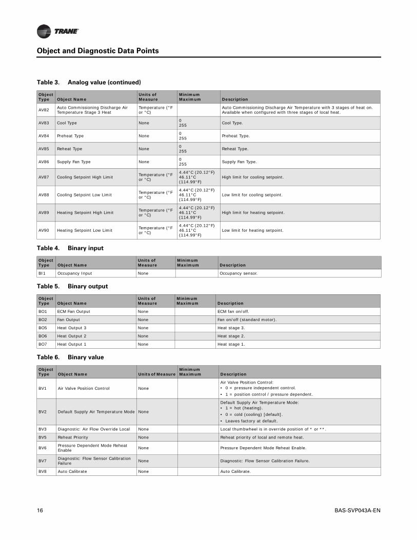
Object and Diagnostic Data Points
For quick reference, the following tables are listed and sorted two different ways. Table 1 through Table 8 are listed by input/output type and sorted by object type. For easy reference, Table 9, p. 18 lists all object types provided in the tables 3 through 10 and is sorted by object name. In addition, this table provides specific configurations that apply to each point shown under the last five columns. Refer to the footnote at the end of this table for information related to the entries in these columns.
Note: Not all points are available to the user. The available data points are defined and dependent on the type of equipment and options.
Table 1. Analog inputs
Object Type Object Name
Units of Measure
MinimumMaximum Description
AI1 Space Temperature Local Temperature (°F or °C)
15°C (59°F)50°C (122°F) Temperature sensor in the space.
AI2 Space Temperature Setpoint Local Temperature (°F or °C)
10°C (50°F)29.4°C (84.92°F) Zone sensor thumbwheel.
BAS-SVP043A-EN 11
Object and Diagnostic Data Points
AI3 Pressure 1
Gaseous Pressure (in H2O, in Hg, mm H2O, mm Hg, Pa, kPa)
0 pascals498 pascals
• Pressure across the flow ring.• 120% flow indicates 2 in H2O (498 pascals) across flow ring.
AI4 Discharge Air Temperature Temperature (°F or °C)
-40°C (-40°F)100°C (212°F) Discharge air temperature sensor wire to the controller.
AI5 Supply Air Temperature Local Temperature (°F or °C)
-40°C (-40°F)100°C (212°F) Supply air temperature sensor wired to the controller.
AI6 Actual Air Valve Position Percentage (%) Valve position on % open.
AI7 Actual Reheat Position Percentage (%) Reheat valve position in % open.
AI8 Space CO2 Concentration Local Parts-per-million 0 ppm5,000 ppm Space CO2 concentration in ppm.
AI9 Air Valve 1 Stroke Time None
60,000 milliseconds570,000 milliseconds
Air valve stroke time in milliseconds (100-millisecond resolution).
AI10 Minimum Actuator Time None 100 milliseconds1,000 milliseconds
• Air valve minimum actuator time 100-millisecond increments.• Minimum 500 milliseconds.
AI11 Water Valve Maximum Stroke Time None 60 milliseconds240 milliseconds This is used for remote or local modulating water heat valve. In milliseconds.
AI12 Water Valve Minimum Actuator Time None 100 milliseconds1,000 milliseconds Water valve minimum actuator time 100-millisecond increments.
Table 2. Analog output
Object Type Object Name
Units of Measure
MinimumMaximum Description
AO1 Air Valve Drive Command Percentage (%) Value of AO is the requested % open.Note: Refer to Actual Air Valve Position.
AO2 Supply Fan Speed Percentage (%) Supply fan in percent. For single-speed fans (0% = OFF, 100% = ON).
AO3 Heating Valve Command Percentage (%) Modulating reheat valve. This is the requested position in percent.Note: Refer to Heating Capacity Secondary for actual water valve position.
Table 1. Analog inputs (continued)
Object Type Object Name
Units of Measure
MinimumMaximum Description
12 BAS-SVP043A-EN
Object and Diagnostic Data Points
Table 3. Analog value
Object Type Object Name
Units of Measure
MinimumMaximum Description
AV2 Air Flow Minimum Setpoint Active
Gaseous Pressure (in H2O, in Hg, mm H2O, mm Hg, Pa, kPa)
Air Flow Minimum Setpoint Active.
AV8 Air Flow Nominal Status
Gaseous Pressure (in H2O, in Hg, mm H2O, mm Hg, Pa, kPa)
0 L/s10,000 L/s Nominal airflow set by configurator based on the unit size selected.
AV9 Reheat Enable Point Temperature (°F or °C)
10°C (50°F)100°C (212°F) Reheat Enable Point.
AV10 Auto Changeover Point Temperature (°F or °C)
10°C (50°F)100°C (212°F Auto Changeover Point.
AV12 Heat Output Secondary Status Percentage (%)
Percent output value (not the same as capacity in all cases). • For modulating this is the valve position.• For PWM, this is the capacity.• For Staged, are the discrete values for each stage (for example, 2 stage is
Space temperature communicated from BAS. If used, the Tracer SC will write to this point once every 15 minutes, but ONLY if this point is put into Service. If the point is in service, but not written to every 15 minutes the controller will put the point into fault status. Factory default is Out of Service. To use this point, put Into Service.
AV15 Air Flow Override Percent None 0%100% Air Flow Override Percent.
AV16 Discharge Air Temperature Setpoint BAS
Temperature (°F or °C)
-7.22°C (19.00°F)21.11°C (69.99°F)
• Only for VFC configuration.• Discharge air temp setpoint communicated from BAS.• Factory default is Out of Service. To use this point, put Into Service.
AV18 Air Flow Gain None 0.0002.000
Default setting is 1.0 and can be edited based on the results of an air balancing test.
AV19 Air Flow Measurement Offset Percentage (%) -50.000%50.000% Set when air balancing.
AV22 Space CO2 Concentration BAS Parts-per-million 0 ppm5,000 ppm
Space CO2 concentration communicated from the BAS in ppm. If used, the system will write to this point once every 15 minutes. Otherwise, the controller will put the point into fault status. Factory default is Out of Service. To use this point, put Into Service.
AV23 Unoccupied Cooling Setpoint Temperature (°F or °C)
4.44°C (20.12°F)46.11°C (114.99°F)
Unoccupied Cooling Setpoint.
AV24 Unoccupied Heating Setpoint Temperature (°F or °C)
-10,000 L/s10,000 L/s Flow set point of Flow Tracking box relative to supply air VAV box.
AV27 Space Temperature Setpoint BAS Temperature (°F or °C)
-10°C (14°F)35°C (95°F)
Communicated setpoint. Factory default is Out of Service. To use this point, put Into Service. If used with a Tracer SC, the SC will place the point In Service during installation.
AV28 Space Temperature Setpoint Active Temperature (°F or °C)
-5.6°C (21.92°F)56.1°C (132.98°F) Space temperature setpoint being used by algorithm.
BAS-SVP043A-EN 13
Object and Diagnostic Data Points
AV29 Supply Air Temperature BAS Temperature (°F or °C)
0°C (32°F)100°C (212°F)
Supply air temperature communicated from BAS. Factory default is Out of Service. To use this point, put Into Service. If used with a Tracer SC, the SC will place the point In Service during installation.
AV36 Ventilation Ratio Percentage (%) 0%–100%. Percentage indicates the required ratio or outdoor air-to-primary air needed to meet zone ventilation requirements.
AV37 Space Temp Setpoint Default Temperature (°F or °C)
4.44°C (20.12°F)46.11°C (114.99°F)
Default space temperature setpoint stored in the controller and set by service tool.
This is limited by Ventilation Setpoint Local and Ventilation Setpoint Standby. Factory default is Out of Service. To use this point, put Into Service.
AV50 Space CO2 Concentration Active Parts-per-million 0 ppm5,000 ppm Space CO2 concentration in ppm, used by algorithm.
AV51 Ventilation Ratio Limit BAS Percentage (%) 0%100%
Ventilation Ratio Limit from the BAS in percent. Factory default is Out of Service. To use this point, put Into Service. If used with a Tracer SC, the SC will place the point In Service during installation.
AV52 PD Mode Min Air Valve Position Percentage (%) 0.0%100.0% Minimum air valve position in percent when using pressure dependent control.
AV53 ECM Fan Correction Factor None 065,535 ECM Fan Correction Factor. Exists if configured only with ECM fan.
Used to override fan speed.• 0% = fan Off.• 100% = On/Off fan override on, ECM at 100%.• 1%–99% = ECM fan at the specified %, On/Off fan is ON.• 101% and greater is default (no override).
Trane has a policy of continuous product and product data improvement and reserves the right to change design and specifications without notice. We are committed to using environmentally conscious print practices.
Trane - by Trane Technologies (NYSE: TT), a global climate innovator - creates comfortable, energy efficient indoor environments for commercial and residential applications. For more information, please visit trane.com or tranetechnologies.com.