Integration of 3-dimensional surgical and orthodontic technologies with orthognathic “surgery-first” approach in the management of unilateral condylar hyperplasia Nandakumar Janakiraman, a Mark Feinberg, b Meenakshi Vishwanath, c Yasas Shri Nalaka Jayaratne, c Derek M. Steinbacher, d Ravindra Nanda, e and Flavio Uribe f Farmington, Shelton, and New Haven, Conn Recent innovations in technology and techniques in both surgical and orthodontic fields can be integrated, espe- cially when treating subjects with facial asymmetry. In this article, we present a treatment method consisting of 3- dimensional computer-aided surgical and orthodontic planning, which was implemented with the orthognathic surgery-first approach. Virtual surgical planning, fabrication of surgical splints using the computer-aided design/computer-aided manufacturing technique, and prediction of final orthodontic occlusion using virtual plan- ning with robotically assisted customized archwires were integrated for this patient. Excellent esthetic and occlusal outcomes were obtained in a short period of 5.5 months. (Am J Orthod Dentofacial Orthop 2015;148:1054-66) T he advent of the digital era has enabled clinicians to use the best available data for evidence-based diagnosis, treatment planning, and execution of treatment. For accurate diagnosis, obtaining precise information from the imaging of the orofacial region in 3 dimensions is absolutely necessary to complement the clinical examination and a thorough medical and dental history, especially when treating complex maloc- clusions with orthognathic surgery. 1 Traditionally, 2-dimensional (2D) imaging has been the standard for representing the 3-dimensional (3D) craniofacial region However, the most common problems with 2D imaging are image distortion, magnification errors, and landmark identification errors. 2,3 With conventional treatment planning for orthognathic surgery using 2D imaging, treatment outcomes have been reported to be suboptimal, especially in patients requiring correction of pitch, roll, and yaw (ie, facial asymmetry). 4 With the introduction of 3D cone-beam computed tomography (CBCT), it has become possible to circum- vent the above shortcomings. Image distortion and er- rors in landmark identification have been minimized, and the actual measurements (linear skeletal measure- ments, overjet, overbite, spacing, and dental arch widths) can be obtained accurately. 5-7 Hence, the scope for applying 3D CBCT imaging has widened from image diagnosis to accurate quantification of the dimensions of the orofacial structures. 5-7 Additionally, it is now possible to visualize the virtual patient by creating an integral fusion model combining the data from all 3 important tissue groups using a CBCT reconstructed bony volume, digital dental models, and a textured facial soft tissue image. 8 This model is highly effective in precisely diagnosing the problem in all 3 spatial planes. Furthermore, the fusion model has a Assistant professor, Division of Orthodontics, Department of Craniofacial Sci- ences, School of Dental Medicine, University of Connecticut, Farmington, Conn. b Clinical instructor, Division of Orthodontics, Department of Craniofacial Sci- ences, School of Dental Medicine, University of Connecticut, Farmington, Conn; private practice, Shelton, Conn. c Postgraduate resident, Division of Orthodontics, Department of Craniofacial Sciences, School of Dental Medicine, University of Connecticut, Farmington, Conn. d Associate professor of surgery (plastic); assistant professor of pediatrics; director of Dental Services, Oral Maxillofacial and Craniofacial surgery, School of Medi- cine, Yale University, New Haven, Conn. e Professor and head, Department of Craniofacial Sciences, Alumni Endowed Chair, School of Dental Medicine, University of Connecticut, Farmington, Conn. f Associate professor and program director, Division of Orthodontics, Department of Craniofacial Sciences, Charles Burstone Professor, School of Dental Medicine, University of Connecticut, Farmington, Conn. All authors have completed and submitted the ICMJE Form for Disclosure of Po- tential Conflicts of Interest, and none were reported. Address correspondence to: Nandakumar Janakiraman, Division of Orthodontics, University of Connecticut Health Center, 263 Farmington Ave, Farmington, CT 06030; e-mail, [email protected]. Submitted, November 2014; revised and accepted, August 2015. 0889-5406/$36.00 Copyright Ó 2015 by the American Association of Orthodontists. http://dx.doi.org/10.1016/j.ajodo.2015.08.012 1054 CLINICIAN'S CORNER
Transcript
CLINICIAN'S CORNER
Integration of 3-dimensional surgical andorthodontic technologies with orthognathic“surgery-first” approach in the management ofunilateral condylar hyperplasia
Nandakumar Janakiraman,a Mark Feinberg,b Meenakshi Vishwanath,c Yasas Shri Nalaka Jayaratne,c
Derek M. Steinbacher,d Ravindra Nanda,e and Flavio Uribef
Recent innovations in technology and techniques in both surgical and orthodontic fields can be integrated, espe-cially when treating subjects with facial asymmetry. In this article, we present a treatment method consisting of 3-dimensional computer-aided surgical and orthodontic planning, which was implemented with the orthognathicsurgery-first approach. Virtual surgical planning, fabrication of surgical splints using the computer-aideddesign/computer-aided manufacturing technique, and prediction of final orthodontic occlusion using virtual plan-ning with robotically assisted customized archwires were integrated for this patient. Excellent esthetic andocclusal outcomes were obtained in a short period of 5.5 months. (Am J Orthod Dentofacial Orthop2015;148:1054-66)
The advent of the digital era has enabled cliniciansto use the best available data for evidence-baseddiagnosis, treatment planning, and execution of
treatment. For accurate diagnosis, obtaining preciseinformation from the imaging of the orofacial regionin 3 dimensions is absolutely necessary to complementthe clinical examination and a thorough medical and
tant professor, Division of Orthodontics, Department of Craniofacial Sci-, School of Dental Medicine, University of Connecticut, Farmington, Conn.cal instructor, Division of Orthodontics, Department of Craniofacial Sci-, School of Dental Medicine, University of Connecticut, Farmington,; private practice, Shelton, Conn.raduate resident, Division of Orthodontics, Department of Craniofacialces, School of Dental Medicine, University of Connecticut, Farmington,.ciate professor of surgery (plastic); assistant professor of pediatrics; directorntal Services, Oral Maxillofacial and Craniofacial surgery, School of Medi-Yale University, New Haven, Conn.ssor and head, Department of Craniofacial Sciences, Alumni EndowedSchool of Dental Medicine, University of Connecticut, Farmington, Conn.iate professor and program director, Division of Orthodontics, Departmentniofacial Sciences, Charles Burstone Professor, School of Dental Medicine,rsity of Connecticut, Farmington, Conn.thors have completed and submitted the ICMJE Form for Disclosure of Po-l Conflicts of Interest, and none were reported.ss correspondence to: Nandakumar Janakiraman, Division of Orthodontics,rsity of Connecticut Health Center, 263 Farmington Ave, Farmington,030; e-mail, [email protected], November 2014; revised and accepted, August 2015.5406/$36.00ight � 2015 by the American Association of Orthodontists./dx.doi.org/10.1016/j.ajodo.2015.08.012
4
dental history, especially when treating complex maloc-clusions with orthognathic surgery.1 Traditionally,2-dimensional (2D) imaging has been the standard forrepresenting the 3-dimensional (3D) craniofacial regionHowever, the most common problems with 2D imagingare image distortion, magnification errors, and landmarkidentification errors.2,3 With conventional treatmentplanning for orthognathic surgery using 2D imaging,treatment outcomes have been reported to besuboptimal, especially in patients requiring correctionof pitch, roll, and yaw (ie, facial asymmetry).4
With the introduction of 3D cone-beam computedtomography (CBCT), it has become possible to circum-vent the above shortcomings. Image distortion and er-rors in landmark identification have been minimized,and the actual measurements (linear skeletal measure-ments, overjet, overbite, spacing, and dental archwidths) can be obtained accurately.5-7 Hence, thescope for applying 3D CBCT imaging has widenedfrom image diagnosis to accurate quantification of thedimensions of the orofacial structures.5-7 Additionally,it is now possible to visualize the virtual patient bycreating an integral fusion model combining the datafrom all 3 important tissue groups using a CBCTreconstructed bony volume, digital dental models, anda textured facial soft tissue image.8 This model is highlyeffective in precisely diagnosing the problem in all 3spatial planes. Furthermore, the fusion model has
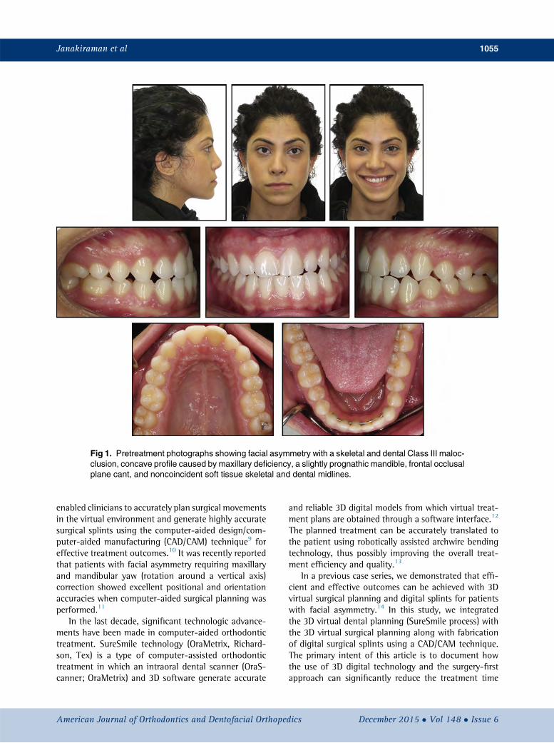
Fig 1. Pretreatment photographs showing facial asymmetry with a skeletal and dental Class III maloc-clusion, concave profile caused by maxillary deficiency, a slightly prognathic mandible, frontal occlusalplane cant, and noncoincident soft tissue skeletal and dental midlines.
Janakiraman et al 1055
enabled clinicians to accurately plan surgical movementsin the virtual environment and generate highly accuratesurgical splints using the computer-aided design/com-puter-aided manufacturing (CAD/CAM) technique9 foreffective treatment outcomes.10 It was recently reportedthat patients with facial asymmetry requiring maxillaryand mandibular yaw (rotation around a vertical axis)correction showed excellent positional and orientationaccuracies when computer-aided surgical planning wasperformed.11
In the last decade, significant technologic advance-ments have been made in computer-aided orthodontictreatment. SureSmile technology (OraMetrix, Richard-son, Tex) is a type of computer-assisted orthodontictreatment in which an intraoral dental scanner (OraS-canner; OraMetrix) and 3D software generate accurate
American Journal of Orthodontics and Dentofacial Orthoped
and reliable 3D digital models from which virtual treat-ment plans are obtained through a software interface.12
The planned treatment can be accurately translated tothe patient using robotically assisted archwire bendingtechnology, thus possibly improving the overall treat-ment efficiency and quality.13
In a previous case series, we demonstrated that effi-cient and effective outcomes can be achieved with 3Dvirtual surgical planning and digital splints for patientswith facial asymmetry.14 In this study, we integratedthe 3D virtual dental planning (SureSmile process) withthe 3D virtual surgical planning along with fabricationof digital surgical splints using a CAD/CAM technique.The primary intent of this article is to document howthe use of 3D digital technology and the surgery-firstapproach can significantly reduce the treatment time
in a patient with facial asymmetry caused by unilateralcondylar hyperplasia.
CASE REPORT
A 23-year-old Middle Eastern woman reported to theorthodontic clinic at the University of Connecticut withthe primary complaint that her jaw was shifting to theleft side, and she wanted her bite fixed (Fig 1). Herpast dental history showed a consultation with an oralsurgeon 4 years previously during which a slight facialasymmetry with the chin point deviated toward the leftside was documented. A subsequent clinical examina-tion showed that her facial asymmetry had worsened,with the chin point deviated toward the left side of thefacial midline by 4 mm. The patient was referred for a
Journal of Orthodontics and Dentofacial Orthopedics
Fig 4. Pretreatment integral fusion model combining the CBCT scan, the dental models, and the 3Dphotographs.
Janakiraman et al 1057
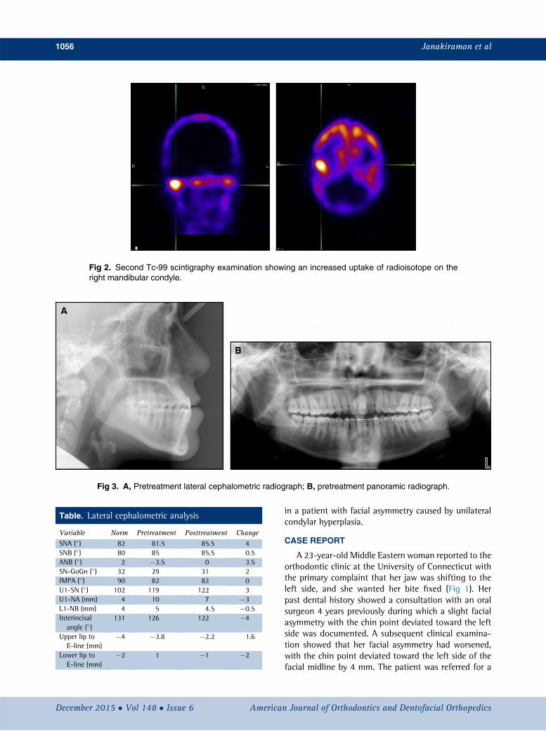
Technetium (Tc)-99 single photon emission computedtomography scintigraphy examination, and the radi-ology report suggested right unilateral condylar hyper-plasia. Since condylar hyperactivity is expected tosubside during the second and third decades of life,the surgeon recommended reevaluating her 9 to
American Journal of Orthodontics and Dentofacial Orthoped
12 months later. However, a second Tc-99 scan taken9 months later again showed hyperactivity of the rightmandibular condyle (Fig 2).
The extraoral examination showed facial asymmetrywith the chin point deviated toward the left side of herface by 4 mm. Additionally, a deviated nasal septum
ics December 2015 � Vol 148 � Issue 6
Fig 5. Virtual 3D surgical plan showing the maxillary movements:A, preoperative maxillary position;Band C, LeFort I osteotomy with clockwise rotation of the maxilla with the center of rotation at the maxil-lary incisal edge. Unilateral maxillary impaction (right side) for the correction of the occlusal cant isseen.
Fig 6. Virtual 3D surgical plan showing the mandibular asymmetric setback with the bilateral sagittalsplit osteotomy for the correction of the mandibular deformity in the yaw plane. Yellow representsthe proximal segment of the mandible after the planned bilateral sagittal split osteotomy. Purple repre-sents the distal segment of the mandible. With the asymmetric movement of the mandible to the rightside, the distal segment overlaps the proximal segment. Themagnitude of the overlap is expressed at 3levels in the corpus of the mandible on the right side. Since the mandible is rotating around the sagittalsplit osteotomy on the left, no overlap between the proximal and distal segments is observed in the vir-tual plan.
1058 Janakiraman et al
December 2015 � Vol 148 � Issue 6 American Journal of Orthodontics and Dentofacial Orthopedics
Fig 7. Superimposition of mirrored left normal hemi-mandible on right side: A, lateral view; B, superior view;C and D, 3D color maps demonstrate distance differ-ences between the superimposed surfaces. Red illus-trates a more positive surface (13.7 mm) in relation tothe left normal hemimandible. Green illustrates morenegative surface (�7.4 mm) in relation to the left normalhemimandible.
Fig 8. A and B, Frontal and profile views before surgery;C and D, the final outcome of the virtual simulation of the3D surgical plan.
Janakiraman et al 1059
toward the right side further accentuated the facialasymmetry. The extraoral frontal examination at restshowed a noticeable intercommissure cant and a para-nasal deficiency, and the soft tissue lower border ofthe mandible was inferior on the right side comparedwith the left side (Fig 1). A concave profile caused by acombination of maxillary deficiency and a prognathicmandible was observed (Fig 3, A; Table). Dentally, thepatient had a bilateral Class III molar relationship thatwas more accentuated on the right side with an edge-to-edge bite anteriorly. An occlusal cant was evident,with the left buccal segment more coronal. The mandib-ular midline was deviated to the left side by 4 mm inreference to the facial midline. She had retroclinedmandibular incisors and proclined maxillary incisors,indicating anteroposterior dental compensations forthe underlying Class III skeletal relationship. Her smileshowed a maxillary cant with a greater gingival displayon the right side. The maxillary and mandibular archeswere well aligned because she had prior orthodontictreatment. The panoramic x-ray showed different
American Journal of Orthodontics and Dentofacial Orthoped
morphologies of the condyles and ramus lengths be-tween the right and left sides (Fig 3, B).
The main treatment objectives were to preventfurther worsening of the asymmetry caused by the activeunilateral condylar hyperplasia, improve her facialesthetics and occlusion, and minimize the overall treat-ment time. Based on the guidelines of Wolford et al,15
treatment options of either high condylectomy and or-thognathic surgery or orthognathic surgery when thehyperactivity of the condyle subsides were offered tothe patient. She accepted the high condylectomy and or-thognathic surgery-first approach for the correction ofher facial asymmetry. The treatment goals consisted ofpreventing the worsening of facial asymmetry;improving her soft tissue profile; correlating her dental,skeletal, and soft tissue midlines to the facial midline;leveling her frontal occlusal plane; and improving hersmile esthetics.
In this patient, both the surgical and orthodonticcorrections were planned virtually. For the surgicalplan, 3 weeks before the surgery, after indirect bondingof the orthodontic appliances (0.022-in preadjusted
ics December 2015 � Vol 148 � Issue 6
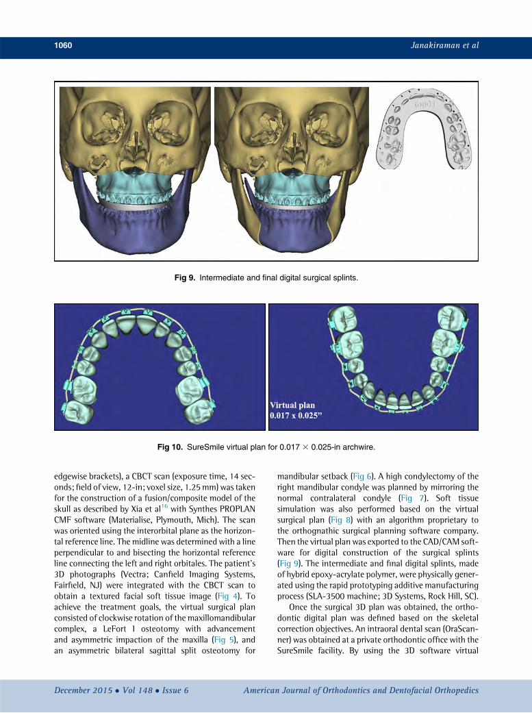
Fig 9. Intermediate and final digital surgical splints.
Fig 10. SureSmile virtual plan for 0.017 3 0.025-in archwire.
1060 Janakiraman et al
edgewise brackets), a CBCT scan (exposure time, 14 sec-onds; field of view, 12-in; voxel size, 1.25mm) was takenfor the construction of a fusion/composite model of theskull as described by Xia et al16 with Synthes PROPLANCMF software (Materialise, Plymouth, Mich). The scanwas oriented using the interorbital plane as the horizon-tal reference line. The midline was determined with a lineperpendicular to and bisecting the horizontal referenceline connecting the left and right orbitales. The patient's3D photographs (Vectra; Canfield Imaging Systems,Fairfield, NJ) were integrated with the CBCT scan toobtain a textured facial soft tissue image (Fig 4). Toachieve the treatment goals, the virtual surgical planconsisted of clockwise rotation of the maxillomandibularcomplex, a LeFort I osteotomy with advancementand asymmetric impaction of the maxilla (Fig 5), andan asymmetric bilateral sagittal split osteotomy for
December 2015 � Vol 148 � Issue 6 American
mandibular setback (Fig 6). A high condylectomy of theright mandibular condyle was planned by mirroring thenormal contralateral condyle (Fig 7). Soft tissuesimulation was also performed based on the virtualsurgical plan (Fig 8) with an algorithm proprietary tothe orthognathic surgical planning software company.Then the virtual plan was exported to the CAD/CAM soft-ware for digital construction of the surgical splints(Fig 9). The intermediate and final digital splints, madeof hybrid epoxy-acrylate polymer, were physically gener-ated using the rapid prototyping additive manufacturingprocess (SLA-3500 machine; 3D Systems, Rock Hill, SC).
Once the surgical 3D plan was obtained, the ortho-dontic digital plan was defined based on the skeletalcorrection objectives. An intraoral dental scan (OraScan-ner) was obtained at a private orthodontic office with theSureSmile facility. By using the 3D software virtual
Journal of Orthodontics and Dentofacial Orthopedics
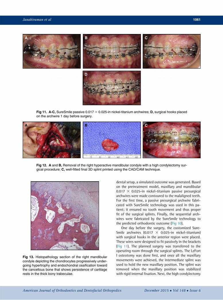
Fig 11. A-C, SureSmile passive 0.0173 0.025-in nickel-titanium archwires; D, surgical hooks placedon the archwire 1 day before surgery.
Fig 12. A and B, Removal of the right hyperactive mandibular condyle with a high condylectomy sur-gical procedure; C, well-fitted final 3D splint printed using the CAD/CAM technique.
Fig 13. Histopathology section of the right mandibularcondyle depicting the chondrocytes progressively under-going hypertrophy and endochondral ossification towardthe cancellous bone that shows persistence of cartilagerests in the thick bony trabeculae.
Janakiraman et al 1061
American Journal of Orthodontics and Dentofacial Orthoped
dental setup, a simulated outcome was generated. Basedon the pretreatment model, maxillary and mandibular0.017 3 0.025-in nickel-titanium passive presurgicalarchwires were made contoured to the malaligned teeth.For the first time, a passive presurgical archwire fabri-cated with SureSmile technology was used in this pa-tient; it ensured no tooth movement and thus properfit of the surgical splints. Finally, the sequential arch-wires were fabricated by the SureSmile technology tothe predicted orthodontic outcome (Fig 10).
One day before the surgery, the customized Sure-Smile archwires (0.017 3 0.025-in nickel-titanium)with surgical hooks in the anterior region were placed.These wires were designed to fit passively in the brackets(Fig 11). The planned surgery was transferred to theoperating room through the surgical splints. The LeFortI osteotomy was done first, and once all the maxillarymovements were achieved, the intermediate splint wasused to hold the new maxillary position. The splint wasremoved when the maxillary position was stabilizedwith rigid internal fixation. Next, the high condylectomy
ics December 2015 � Vol 148 � Issue 6
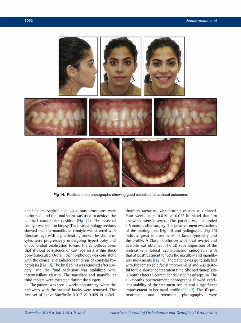
Fig 14. Posttreatment photographs showing good esthetic and occlusal outcomes.
1062 Janakiraman et al
and bilateral sagittal spilt osteotomy procedures wereperformed, and the final splint was used to achieve theplanned mandibular position (Fig 12). The resectedcondyle was sent for biopsy. The histopathology sectionsshowed that the mandibular condyle was covered withfibrocartilage with a proliferating zone. The chondro-cytes were progressively undergoing hypertrophy andendochondral ossification toward the cancellous bonethat showed persistence of cartilage rests within thickbony trabeculae. Overall, the morphology was consistentwith the clinical and radiologic findings of condylar hy-perplasia (Fig 13). The final splint was removed after sur-gery, and the final occlusion was stabilized withintermaxillary elastics. The maxillary and mandibularthird molars were extracted during the surgery.
The patient was seen 2 weeks postsurgery, when thearchwires with the surgical hooks were removed. Thefirst set of active SureSmile 0.017 3 0.025-in nickel-
December 2015 � Vol 148 � Issue 6 American
titanium archwires with seating elastics was placed.Four weeks later, 0.019 3 0.025-in nickel-titaniumarchwires were inserted. The patient was debonded4.5 months after surgery. The posttreatment evaluationsof the photographs (Fig 14) and radiographs (Fig 15)indicate great improvements in facial symmetry andthe profile. A Class I occlusion with ideal overjet andoverbite was obtained. The 2D superimposition of thepretreatment lateral cephalometric radiograph withthat at posttreatment reflects the maxillary and mandib-ular movements (Fig 16). The patient was quite satisfiedwith the remarkable facial improvement and was grate-ful for the shortened treatment time. She had rhinoplasty8 months later to correct her deviated nasal septum. The11-months posttreatment photographs showed excel-lent stability of the treatment results and a significantimprovement in her nasal profile (Fig 17). The 3D pre-treatment and retention photographs were
Journal of Orthodontics and Dentofacial Orthopedics
Fig 16. Superimposition of pretreatment and posttreat-ment lateral cephalograms.
superimposed on the forehead and the nasal root, andFigure 18 shows the soft tissue changes.
DISCUSSION
Unilateral condylar hyperplasia is a self-limiting con-dition occurring between 10 and 30 years of age withequal distribution between male and female subjects.17
American Journal of Orthodontics and Dentofacial Orthoped
The unilateral excessive growth of the mandibularcondyle may result in significant dental, skeletal, andsoft tissue asymmetry. In these patients, bone scanning(Tc-99) is routinely used to evaluate the hyperactivity ofthe condyles. However, the gold standard for diagnosisof condylar hyperplasia is correlating the clinical find-ings with the bone scan.17 This is because the sensitivityof the bone scan depends on the type of scintigraphystudy. A recent meta-analysis compared the sensitivity(true positive) and specificity (true negative) of a planarbone scan and the single photon emission computed to-mography scanning technique in the diagnosis of unilat-eral condylar hyperplasia.18 The sensitivity of the singlephoton emission computed tomography scan (0.91)was higher than that for the planar bone scan (0.70),whereas the specificity for the 2 techniques was similar(0.9).
Surgical correction of facial asymmetry is compli-cated because it usually involves all 3 dimensions ofspace. Conventional planning has significant limita-tions, since the planned corrections are based on 1 planeor 2 planes of space provided by 2D radiographs, limitingthe possibility of fully visualizing the effects of thecorrection of 1 dimension over the others.19 Addition-ally, condylar positional changes and interferences be-tween the proximal and distal segments cannot bepredicted.20 However, these shortcomings can be mini-mized or overcome with 3D virtual surgical planning.11
De Riu et al19 evaluated the correction of facial asymme-try by comparing the outcomes of conventional and 3Dsurgical planning. In their randomized clinical trial, theyfound that the alignment of the maxillary and mandib-ular dental midlines, the agreement between themandibular midline and the facial midline, and the
ics December 2015 � Vol 148 � Issue 6
Fig 17. Records at 11 months posttreatment showing excellent stability of the interdisciplinarytreatment.
1064 Janakiraman et al
agreement of the mandibular sagittal plane with themidsagittal plane were more accurate in the 3D surgicalplanning group.
One major advantage with 3D computer-assistedsurgical planning is the ability to visualize different com-binations of surgical movements to achieve the desiredoutcome. The accurate prediction of the soft tissuechanges after 3D virtual surgery can aid the surgeonand the orthodontist in determining the best treatmentoption.21 Often, in subjects with facial asymmetry, theasymmetry not only is due to the differences in sizeand shape of the hard tissues, but also is complicatedby soft tissue differences between the 2 sides.14 Hence,visualization of the esthetic changes in the planningstage is of paramount importance to patients with facialasymmetry. Additionally, the surgeon can preview thesoft tissue facial outcome and alter the osteotomy cutsand plan for implants or grafting to achieve the desired
December 2015 � Vol 148 � Issue 6 American
outcome.16 In recent years, several soft tissue simulationsoftware programs have been introduced, but fewstudies have validated their accuracy with that of theactual surgical outcome.22
Marchetti et al23 examined the reliability of soft tis-sue simulation using SurgiCase-CMF software. Theycompared the virtual surgical plan with the actualoutcome 6 months after surgery. The differences be-tween the simulated plan and the postsurgical planranged from 0.50 to 1.15 mm, which were less thanthe maximum tolerance level of 2 mm. In 91% of virtualplans, the error was less than 2 mm. Similarly, Bianchiet al21 found that in 86.8% of simulations, the errorwas less than 2 mm. Finally, the authors of both studiesconcluded that the 3D virtual plan with SurgiCase-CMFsoftware could accurately predict the postsurgical facialsoft tissue changes. On the contrary, Terzic et al22 re-ported errors greater than 3 mm in the lower part of
Journal of Orthodontics and Dentofacial Orthopedics
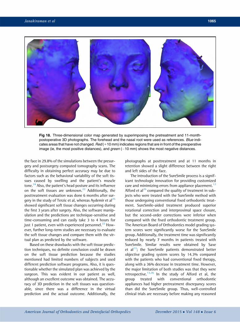
Fig 18. Three-dimensional color map generated by superimposing the pretreatment and 11-month-postoperative 3D photographs. The forehead and the nasal root were used as references. Blue indi-cates areas that have not changed.Red (110mm) indicates regions that are in front of the preoperativeimage (ie, the most positive distances), and green (�10 mm) shows the most negative distances.
Janakiraman et al 1065
the face in 29.8% of the simulations between the presur-gery and postsurgery computed tomography scans. Thedifficulty in obtaining perfect accuracy may be due tofactors such as the behavioral variability of the soft tis-sues caused by swelling and the patient's muscletone.24 Also, the patient's head posture and its influenceon the soft tissues are unknown.22 Additionally, theposttreatment evaluation was done 6 months after sur-gery in the study of Terzic et al, whereas Aydemir et al25
showed significant soft tissue changes occurring duringthe first 3 years after surgery. Also, the software manip-ulation and the predictions are technique-sensitive andtime-consuming and can easily take 3 to 4 hours forjust 1 patient, even with experienced personnel.22 How-ever, further long-term studies are necessary to evaluatethe soft tissue changes and compare them with the vir-tual plan as predicted by the software.
Based on these drawbacks with the soft tissue predic-tion techniques, no definite conclusion could be drawnon the soft tissue prediction because the studiesmentioned had limited numbers of subjects and useddifferent prediction software programs. Also, it is ques-tionable whether the simulated plan was achieved by thesurgeon. This was evident in our patient as well,although an excellent outcome was obtained. The accu-racy of 3D prediction in the soft tissues was question-able, since there was a difference in the virtualprediction and the actual outcome. Additionally, the
American Journal of Orthodontics and Dentofacial Orthoped
photographs at posttreatment and at 11 months inretention showed a slight difference between the rightand left sides of the face.
The introduction of the SureSmile process is a signif-icant technologic innovation for providing customizedcare and minimizing errors from appliance placement.12
Alford et al26 compared the quality of treatment in sub-jects who were treated with the SureSmile method withthose undergoing conventional fixed orthodontic treat-ment. SureSmile-aided treatment produced superiorrotational correction and interproximal space closure,but the second-order corrections were inferior whencompared with the fixed orthodontic treatment group.The American Board of Orthodontics model grading sys-tem scores were significantly worse for the SureSmilegroup. Additionally, the treatment time was significantlyreduced by nearly 7 months in patients treated withSureSmile. Similar results were obtained by Saxeet al13; the SureSmile patients demonstrated betterobjective grading system scores by 14.3% comparedwith the patients who had conventional fixed therapy,along with a 36% decrease in treatment time. However,the major limitation of both studies was that they wereretrospective.13,26 In the study of Alford et al, thegroup treated with conventional orthodonticappliances had higher pretreatment discrepancy scoresthan did the SureSmile group. Thus, well-controlledclinical trials are necessary before making any reasoned
ics December 2015 � Vol 148 � Issue 6
1066 Janakiraman et al
judgment regarding the efficiency and effectiveness ofthe SureSmile technique when compared with conven-tional orthodontic treatment.
In the future, we foresee full integration of 3D surgi-cal and orthodontic planning, where manipulation ofteeth and jaw movements can be done with the samesoftware.
CONCLUSIONS
Integration of 3D computer-aided orthognathic sur-gical protocols with 3D digital orthodontic treatmentmethods (with customized wires in this patient) ispossible. An excellent outcome can be achieved withthese approaches in conjunction with the surgery-firstprotocol. Additionally, evidence supports the use ofcomputer-assisted orthognathic surgical planning inthe management of facial asymmetry.
REFERENCES
1. Harrell WE Jr. 3D diagnosis and treatment planning in orthodon-tics. Semin Orthod 2009;15:35-41.
2. Trpkova B, Major P, Prasad N, Nebbe B. Cephalometric landmarksidentification and reproducibility: a meta-analysis. Am J OrthodDentofacial Orthop 1997;112:165-70.
3. Timock AM, Cook V, McDonald T, Leo MC, Crowe J, Benninger BL,et al. Accuracy and reliability of buccal bone height and thicknessmeasurements from cone-beam computed tomography imaging.Am J Orthod Dentofacial Orthop 2011;140:734-44.
4. Bell RB. Computer planning and intraoperative navigation in or-thognathic surgery. J Oral Maxillofac Surg 2011;69:592-605.
5. Swennen GR, Schutyser F. Three-dimensional cephalometry: spiralmulti-slice vs cone-beam computed tomography. Am J OrthodDentofacial Orthop 2006;130:410-6.
6. Gribel BF, Gribel MN, Frazao DC, McNamara JA Jr, Manzi FR. Ac-curacy and reliability of craniometric measurements on lateralcephalometry and 3D measurements on CBCT scans. Angle Orthod2011;81:26-35.
7. Baumgaertel S, Palomo JM, Palomo L, Hans MG. Reliability andaccuracy of cone-beam computed tomography on dental mea-surements. Am J Orthod Dentofacial Orthop 2009;136:19-25.
8. Plooij JM, Maal TJ, Haers P, Borstlap WA, Kuijpers-Jagtman AM,Berge SJ. Digital three-dimensional image fusion processes forplanning and evaluating orthodontics and orthognathic surgery.A systematic review. Int J Oral Maxillofac Surg 2011;40:341-52.
10. Xia JJ, Shevchenko L, Gateno J, Teichgraeber JF, Taylor TD,Lasky RE, et al. Outcome study of computer-aided surgical simu-lation in the treatment of patients with craniomaxillofacial defor-mities. J Oral Maxillofac Surg 2011;69:2014-24.
11. Hsu SS, Gateno J, Bell RB, Hirsch DL, Markiewicz MR,Teichgraeber JF, et al. Accuracy of a computer-aided surgicalsimulation protocol for orthognathic surgery: a prospective multi-center study. J Oral Maxillofac Surg 2013;71:128-42.
December 2015 � Vol 148 � Issue 6 American
12. Mah J, Sachdeva R. Computer-assisted orthodontic treatment: theSureSmile process. Am J Orthod Dentofacial Orthop 2001;120:85-7.
13. Saxe AK, Louie LJ, Mah J. Efficiency and effectiveness of Sure-Smile. World J Orthod 2010;11:16-22.
14. Uribe F, Janakiraman N, Shafer D, Nanda R. Three-dimensionalcone-beam computed tomography-based virtual treatment plan-ning and fabrication of a surgical splint for asymmetric patients:surgery first approach. Am J Orthod Dentofacial Orthop 2013;144:748-58.
15. Wolford LM, Mehra P, Reiche-Fischel O, Morales-Ryan CA, Garcia-Morales P. Efficacy of high condylectomy for management ofcondylar hyperplasia. Am J Orthod Dentofacial Orthop 2002;121:136-50.
16. Xia JJ, Gateno J, Teichgraeber JF. A new clinical protocol to eval-uate cranio-maxillofacial deformity and to plan surgical correc-tion. J Oral Maxillofac Surg 2009;67:2093-106.
17. Saridin CP, Raijmakers P, Becking AG. Quantitative analysis ofplanar bone scintigraphy in patients with unilateral condylar hy-perplasia. Oral Surg Oral Med Oral Pathol Oral Radiol Endod2007;104:259-63.
18. Saridin CP, Raijmakers P, Tuinzing D, Becking AG. Bone scintig-raphy as a diagnostic method in unilateral hyperactivity of themandibular condyles: a review and meta-analysis of the literature.Int J Oral Maxillofac Surg 2011;40:11-7.
19. De Riu G, Meloni SM, Baj A, Corda A, Soma D, Tullio A. Computer-assisted orthognathic surgery for correction of facial asymmetry:results of a randomised controlled clinical trial. Br J Oral MaxillofacSurg 2014;52:251-7.
20. Yang HJ, LeeWJ, Yi WJ, Hwang SJ. Interferences betweenmandib-ular proximal and distal segments in orthognathic surgery for pa-tients with asymmetric mandibular prognathism depending ondifferent osteotomy techniques. Oral Surg Oral Med Oral PatholOral Radiol Endod 2010;110:18-24.
21. Bianchi A, Muyldermans L, Di Martino M, Lancellotti L, Amadori S,Sarti A, et al. Facial soft tissue esthetic predictions: validation incraniomaxillofacial surgery with cone beam computed tomogra-phy data. J Oral Maxillofac Surg 2010;68:1471-9.
22. Terzic A, Combescure C, Scolozzi P. Accuracy of computationalsoft tissue predictions in orthognathic surgery from three-dimensional photographs 6 months after completion of surgery:a preliminary study of 13 patients. Aesthetic Plast Surg 2014;38:184-91.
23. Marchetti C, Bianchi A, Muyldermans L, Di Martino M,Lancellotti L, Sarti A. Validation of new soft tissue software in or-thognathic surgery planning. Int J Oral Maxillofac Surg 2011;40:26-32.
24. Aboul-Hosn Centenero S, Hernandez-Alfaro F. 3D planning in or-thognathic surgery: CAD/CAM surgical splints and prediction ofthe soft and hard tissues results—our experience in 16 cases. J Cra-niomaxillofac Surg 2012;40:162-8.
25. Aydemir H, Efendiyeva R, Karasu H, Toygar-Memikoglu U.Evaluation of long-term soft tissue changes after bimaxillaryorthognathic surgery in Class III patients. Angle Orthod 2015;85:631-7.
26. Alford TJ, Roberts WE, Hartsfield JK Jr, Eckert GJ, Snyder RJ. Clin-ical outcomes for patients finished with the SureSmile� methodcompared with conventional fixed orthodontic therapy. Angle Or-thod 2011;81:383-8.
Journal of Orthodontics and Dentofacial Orthopedics


![Two-dimensional regularity and exactnessweb.science.mq.edu.au/~rgarner/Papers/2D.pdf · 2014. 10. 27. · [2,3,7,8,10,11,22,23] ... The first author acknowledges the support of the](https://static.documents.pub/doc/80x56/5fd5269dcd6cf7698718fafa/two-dimensional-regularity-and-rgarnerpapers2dpdf-2014-10-27-237810112223.jpg)


![Hierarchy of One-Dimensional Models in Nonlinear Elasticity · to full anisotropic and heterogeneous beams. In the framework of nonlinear elasticity, [9] provides the first attempt](https://static.documents.pub/doc/80x56/5e6c087bb2f1510dab518bba/hierarchy-of-one-dimensional-models-in-nonlinear-elasticity-to-full-anisotropic.jpg)
![REVIEWARTICLE Hang GAO Researchprogressonultra ... · tive photoelastic coefficients, and acousto-optic figures. KDP crystal is the first choice for multi-dimensional acousto-opticaldevice[1,2]andcurrentlytheonlymaterial](https://static.documents.pub/doc/80x56/5fcae95a062b7d63f279a725/reviewarticle-hang-gao-researchprogressonultra-tive-photoelastic-coeficients.jpg)


