1 Beijing Institute of Nanoenergy and Nanosystems, Chinese Academy of Sciences, Beijing 100083, China 2 Collaborative Innovation Center of Chemistry for Energy Materials, College of Chemistry and Chemical Engineering, Xiamen University,
Xiamen 361005, China 3 Department of Materials Science and Engineering, University of Washington, Seattle, Washington 98195, USA 4 School of Material Science and Engineering, Georgia Institute of Technology, Atlanta, Georgia 30332, USA § These authors contributed equally to this work.
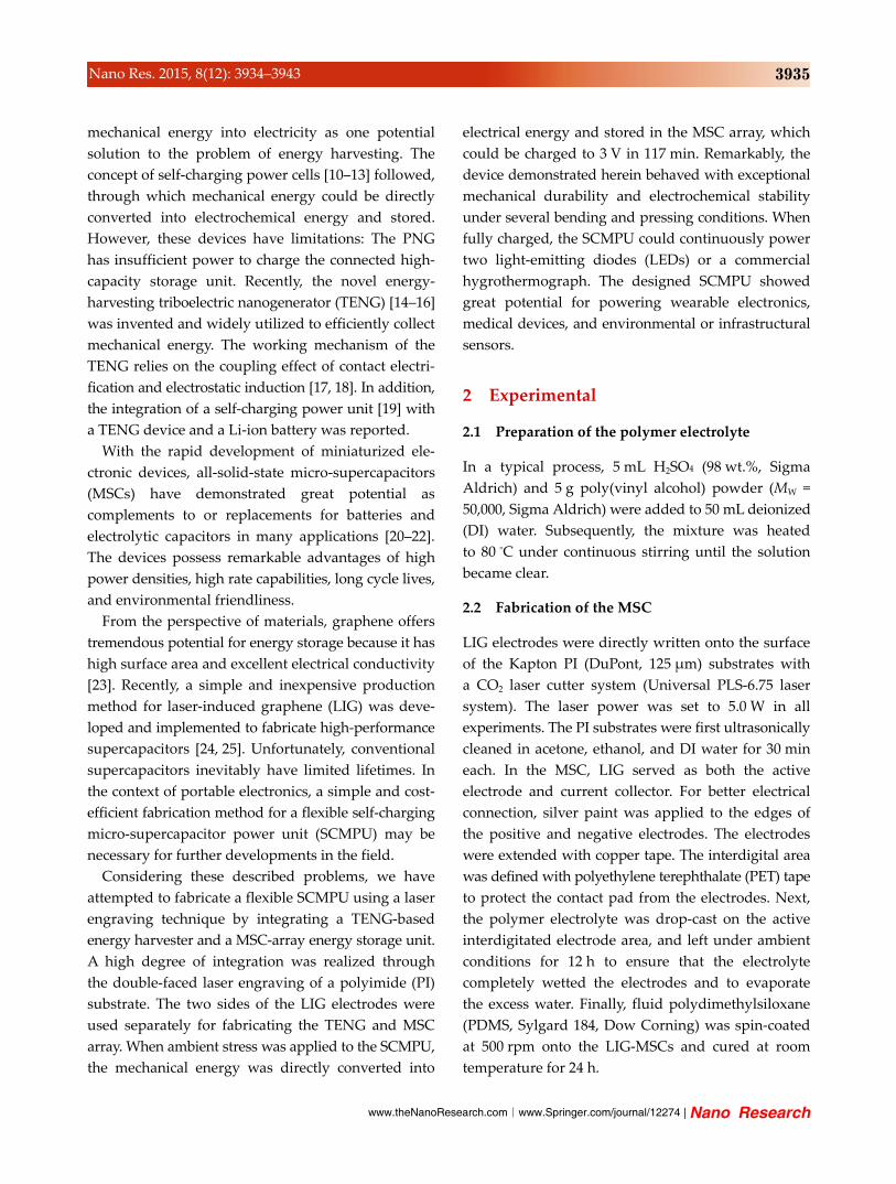
Fig. 1(a). The device contains two primary components
of a flexible MSC array and an arched-structure TENG.
These components were coupled through the double-
faced laser engraving of the uppermost PI substrate
by a commercial CO2 laser cutter system. The two
sides of LIG electrodes were used to fabricate the
TENG and MSC array separately. A schematic of the
laser engraving process is shown in Fig. S1 in the
Electronic Supplementary Material (ESM). Figure 1(b)
shows cross-sectional SEM images of the double-
sided laser-engraved PI substrate. The thickness of LIG
layers on both sides is ~40 μm and separated by an
unexposed middle PI substrate that electrically isolates
the two sides of the LIG. The higher-magnification
SEM image inset in Fig. 1(b) displays the porous mul-
tilayered cross-sectional structure of the LIG. The SEM
images in Fig. 1(c) depict the surface topography of
the LIG, revealing a regular and porous microstruc-
ture written by the laser system, which benefits the
performance of both the MSC array and the TENG.
The HRTEM image in Fig. 1(d) reveals the few-layer
features and ripple-like wrinkled structures of the
thin LIG flakes. This characterization of the LIG is
similar in morphology and graphene properties to that
previously reported [24].
A photograph of a typical 3 cm × 3 cm SCMPU device
is shown in the top inset of Fig. 1(a), demonstrating
the flexibility and arch-shaped structure of the device.
The dimensions of the SCMPU can be further reduced
with the high resolution of the laser system used for
production. To increase the triboelectric charge density
in a large surface area and to enhance the mechanical
robustness of the TENG, the surface of the PTFE thin
Figure 1 (a) Schematic depicting the detailed structure of the SCMPU. Top inset: photograph of SCMPU; bottom: SEM image of PTFE nanoparticles applied onto the surface of PTFE film. (b) Cross-sectional SEM image of a double-sided laser-engraved PI substrate with both sides of LIG. Inset: enlarged SEM image showing porous multilayer morphology of LIG. (c) SEM image of the LIG thin film. Inset: enlarged SEM image. (d) HRTEM image obtained from the edge of a LIG flake.
www.theNanoResearch.com∣www.Springer.com/journal/12274 | Nano Research
3937 Nano Res. 2015, 8(12): 3934–3943
film was modified with a layer of PTFE nanoparticles
[26], as illustrated in the bottom inset of Fig. 1(a). With
this highly integrated SCMPU structure, the MSC
array can be fully charged through the harvesting of
ambient mechanical energy by converting the TENG-
generated alternating current (AC) pulses to a direct
current (DC) with a low-loss full-wave bridge rectifier.
The working principle of the SCMPU is charted in
Fig. S2 in the ESM.
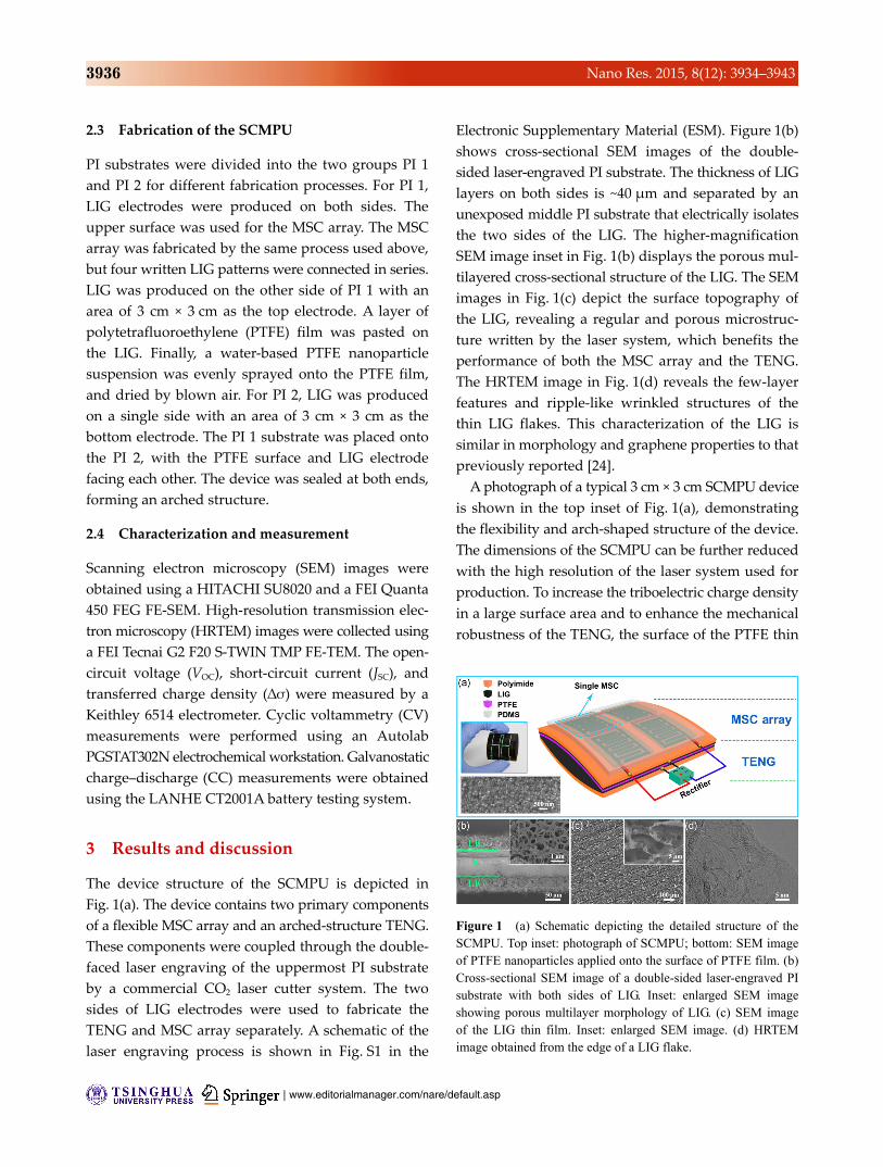
To ensure the feasibility of the proposed device’s
structure, an energy-harvesting component with
high-output performance is essential. Therefore,
characterizing the outputs of the LIG-TENG is
necessary. The electrical output measurement of the
LIG-TENG was performed by a linear mechanical
motor at 0.6 Hz.
In the process of contact–separation, a VOC of ~168 V
is generated between the two electrodes of the LIG-
TENG (Fig. 2(a)). The ∆σ of ~68 μC·m–2 driven by this
potential difference is also measured, as shown in
Fig. 2(b). Consequently, the transfer of the charges
produces an AC output with a peak JSC of 21.3 mA·m–2
corresponding to the contact–separation process
(Fig. 2(c)).
To further investigate the stability of the LIG-TENG,
a periodical pressure was applied at 1 Hz. The voltage
Figure 2 Output performance characterization of the LIG-TENG. (a) Open-circuit voltage (VOC), (b) transferred charge density (∆σ),and (c) short-circuit current density (JSC) generated by the LIG-TENG under periodical deformation at 0.6 Hz. (d) Mechanical durability characterization of the LIG-TENG. At a frequency of 1 Hz for 40,000 cycles, no degradation of the output voltage is experimentallyobserved. (e) The dependence of the output voltage and current density and (f) instantaneous power density of the LIG-TENG on the resistance of external load.
| www.editorialmanager.com/nare/default.asp
3938 Nano Res. 2015, 8(12): 3934–3943
was recorded after each 10,000 loading/unloading
cycles. In each recording, 300 cycles of data are
presented, as shown in Fig. 2(d). The voltage ampli-
tudes exhibit negligible change after 40,000 cycles,
demonstrating the high repeatability, stability, and
durability of the LIG-TENG unit.
Figure 2(e) illustrates the dependence of both voltage
and current density outputs on a series of different
resistances (from 103 Ω to 2 GΩ). The current density
decreases drastically as the external resistance increases,
while the voltage across the load experiences the
opposite trend. Consequently, the effective electrical
power density of the LIG-TENG relates closely to the
external load, reaching a maximum value of 0.8 W·m–2
at a load resistance of 20 MΩ (Fig. 2(f)). Thus, the
output performance of this LIG-TENG is comparable
to that of the conventional metal-based TENG [27, 28]
and much higher than that of the reported graphene-
based TENG [29]. Most importantly, it is simple,
cost-effective, and scale-controllable in production.
This manufacturing technique may have promising
prospects in the application of TENGs in other modes
[30], such as the lateral-sliding and freestanding
triboelectric-layer modes, because of the easy patterning
of the LIG electrodes.
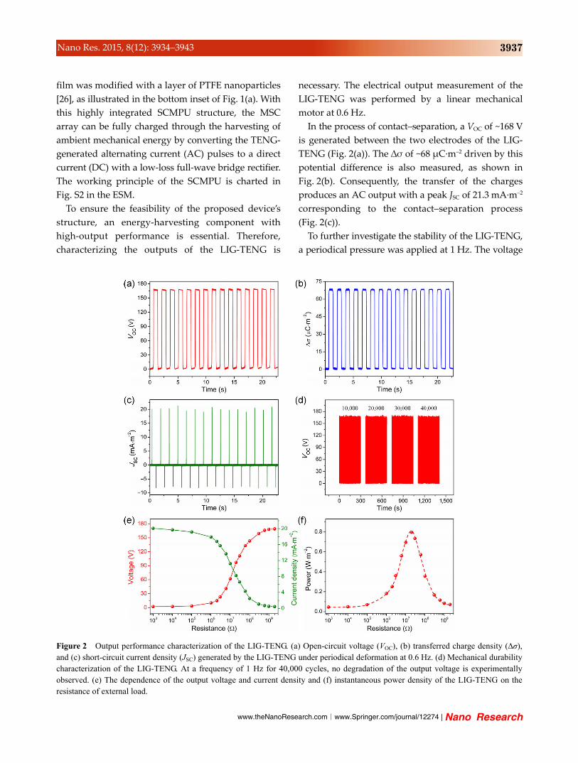
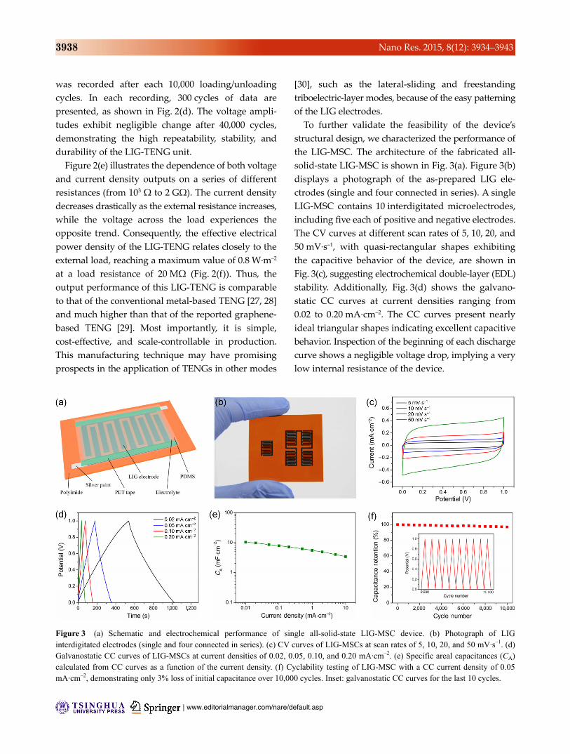
To further validate the feasibility of the device’s
structural design, we characterized the performance of
the LIG-MSC. The architecture of the fabricated all-
solid-state LIG-MSC is shown in Fig. 3(a). Figure 3(b)
displays a photograph of the as-prepared LIG ele-
ctrodes (single and four connected in series). A single
behavior. Inspection of the beginning of each discharge
curve shows a negligible voltage drop, implying a very
low internal resistance of the device.
Figure 3 (a) Schematic and electrochemical performance of single all-solid-state LIG-MSC device. (b) Photograph of LIG interdigitated electrodes (single and four connected in series). (c) CV curves of LIG-MSCs at scan rates of 5, 10, 20, and 50 mV·s–1. (d) Galvanostatic CC curves of LIG-MSCs at current densities of 0.02, 0.05, 0.10, and 0.20 mA·cm–2. (e) Specific areal capacitances (CA) calculated from CC curves as a function of the current density. (f) Cyclability testing of LIG-MSC with a CC current density of 0.05 mA·cm–2, demonstrating only 3% loss of initial capacitance over 10,000 cycles. Inset: galvanostatic CC curves for the last 10 cycles.
www.theNanoResearch.com∣www.Springer.com/journal/12274 | Nano Research
3939 Nano Res. 2015, 8(12): 3934–3943
The areal capacitances (CA) of the LIG-MSC are
calculated from the CC curves by the following
equations
/C I t V (1)
A
/ /C C S I t S V (2)
where C is the total capacitance, I is the discharge
current, ∆t is the discharge time, ∆V is the potential
window on discharging after IR drop, and S is the total
area of the active positive and negative electrodes.
The CA is ~10.29 mF·cm–2 at a current density of
0.01 mA·cm–2 (Fig. 3(e)), comparable to or higher than
those reported in the literature for carbon-based MSCs
[21, 22, 24, 31, 32]. Furthermore, the single LIG-MSC
shows excellent cyclic stability, retaining 97% of the
initial capacitance after 10,000 charge/discharge cycles
(Fig. 3(f)). A typical galvanostatic CC curve under
continuous operation for the last 10 cycles is shown
in the inset of Fig. 3(f). As seen from these results, the
LIG-MSC displayed excellent performance suitable
for integration with the self-charging system.
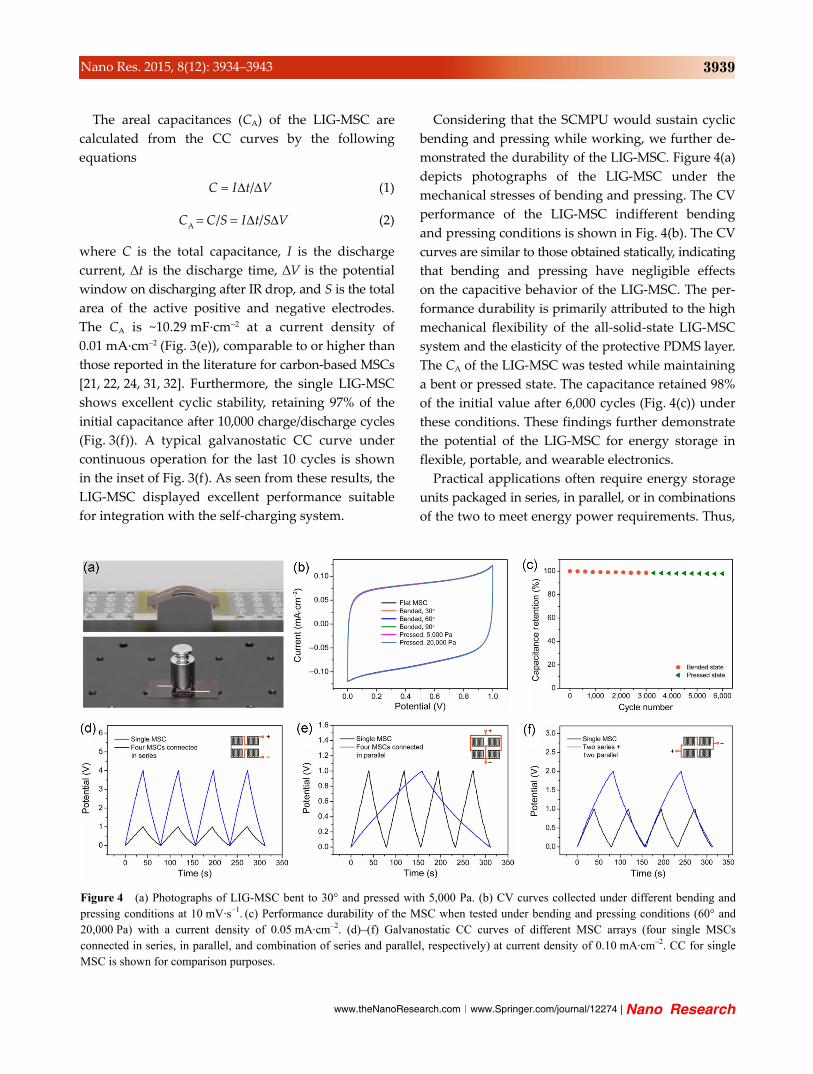
Considering that the SCMPU would sustain cyclic
bending and pressing while working, we further de-
monstrated the durability of the LIG-MSC. Figure 4(a)
depicts photographs of the LIG-MSC under the
mechanical stresses of bending and pressing. The CV
performance of the LIG-MSC indifferent bending
and pressing conditions is shown in Fig. 4(b). The CV
curves are similar to those obtained statically, indicating
that bending and pressing have negligible effects
on the capacitive behavior of the LIG-MSC. The per-
formance durability is primarily attributed to the high
mechanical flexibility of the all-solid-state LIG-MSC
system and the elasticity of the protective PDMS layer.
The CA of the LIG-MSC was tested while maintaining
a bent or pressed state. The capacitance retained 98%
of the initial value after 6,000 cycles (Fig. 4(c)) under
these conditions. These findings further demonstrate
the potential of the LIG-MSC for energy storage in
flexible, portable, and wearable electronics.
Practical applications often require energy storage
units packaged in series, in parallel, or in combinations
of the two to meet energy power requirements. Thus,
Figure 4 (a) Photographs of LIG-MSC bent to 30° and pressed with 5,000 Pa. (b) CV curves collected under different bending and pressing conditions at 10 mV·s−1. (c) Performance durability of the MSC when tested under bending and pressing conditions (60° and 20,000 Pa) with a current density of 0.05 mA·cm–2. (d)–(f) Galvanostatic CC curves of different MSC arrays (four single MSCs connected in series, in parallel, and combination of series and parallel, respectively) at current density of 0.10 mA·cm–2. CC for single MSC is shown for comparison purposes.
| www.editorialmanager.com/nare/default.asp
3940 Nano Res. 2015, 8(12): 3934–3943
MSC arrays of four single MSCs in series, parallel, or
both were designed by the computer-controlled laser
system. As shown in Figs. 4(d)–4(f), the operating
potentials and currents are well controlled by the
different configurations. The MSC arrays reveal nearly
ideal triangular CC curves with minuscule voltage
drops, indicating excellent capacitive properties and
negligible internal resistances. The MSC arrays also
exhibit excellent cycling stability (Fig. S3 in the ESM).
With the resolution of the controllable laser system,
the size of a single MSC can be further reduced and
the MSC array can be easily adjusted into various
combinations for specific applications (Movie S1 in
the ESM).
To preferably match the performance of the MSC
array, the output voltage of the LIG-TENG must be
reduced. At present, two methods can be used to
reduce TENG output voltage. The first method uses a
transformer [33]. However, the use of a transformer
not only causes substantial energy loss but also
adds unnecessary weight and volume to the system.
Furthermore, it is difficult to match the low-frequency
and high-output load resistance properties of the
TENG. The second method reduces the voltage by
reducing the gap distance (d) of the TENG, which
was proven successful in our previous works [34, 35].
This option is much more efficient for the self-
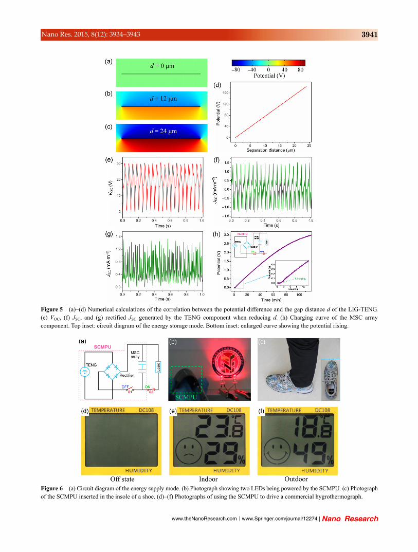
charging system. To theoretically investigate the VOC–d
relationship of the LIG-TENG, a numerical calculation
with finite element methods (FEM) was performed
on the system. For simplicity, the LIG-TENG was
treated as a parallel-plate capacitor in the established
model, in which the PTFE plate with the LIG electrode
was placed parallel to the counter LIG plate with
varied d of 0 to 24 μm. The triboelectric charge density
on the inner surface of PTFE plate was assigned as
68 μC·m–2, equal to the measured transferred charge
density from Fig. 2(b). The calculated potential distri-
bution around the parallel-plate structure is displayed
with color scaling in Figs. 5(a)–5(d). The potential
difference between the top and bottom electrodes
clearly decreases with decreasing d. By utilizing the
numerical calculations, the experimental d of the LIG-
TENG was reduced, with results shown in Figs. 5(e)
and 5(f). When reducing d of the TENG component,
the VOC is reduced to ~30 V, which effectively matches
that of the MSC array, while the JSC was reduced to
~1.5 mA·m–2. This AC output can be rectified to a
unidirectional pulse output by a low-loss full-wave
bridge rectifier (Fig. 5(g)) that generates electricity to
be stored in the MSC array component. While working
in the energy-harvesting mode (top inset of Fig. 5(h),
S1 on; S2 off), the SCMPU converts the mechanical
energy to electrical energy and stores it in the MSC
array component. The charging curve of the MSC
array component is shown in Fig. 5(h). The stored
charge increases steadily with increased charging
time, and the potential reaches 3 V in 117 min.
When a sufficient amount of charge has been stored
in the energy storage mode, the SCMPU proceeds to
the energy-supply mode (S1 off; S2 on). The circuit
diagram of this mode is displayed in Fig. 6(a). Figure
6(b) demonstrates the fully charged SCMPU in use,
simultaneously powering two LEDs with a minimum
operating potential of 1.5 V. The painted area
demonstrates the flexibility of the device. Even when
bent to 90°, the device demonstrates ordinary behavior.
The SCMPU can be inserted into the insole of a
shoe (Fig. 6(c)), indicating potential applications for
wearable electronics. To further demonstrate the
application of the SCMPU, it was successfully utilized
to continuously power a commercial hygrothermograph
(Figs. 6(d)–6(f)), measuring the apparent difference
in temperature and humidity between indoors and
outdoors.
4 Conclusions
Using a simple and cost-effective laser engraving
technique, we have developed a flexible SCMPU
integrating a triboelectric-based energy-harvesting
unit and an electrochemical storage unit into a single
device. The SCMPU exhibited remarkable advantages
such as self-charging capability, high durability, and
environmental friendliness. The LIG-TENG had a
peak power density of 0.8 W·m–2 at a loading resistance
of 20 MΩ. The MSC had a high capacitance of
~10.29 mF·cm–2 at a current density of 0.01 mA·cm–2.
The TENG component efficiently generated electricity
from ambient mechanical vibrations with high output;
the rectified electrical energy was directly stored in
the MSC array component, which could be charged
www.theNanoResearch.com∣www.Springer.com/journal/12274 | Nano Research
3941 Nano Res. 2015, 8(12): 3934–3943
Figure 5 (a)–(d) Numerical calculations of the correlation between the potential difference and the gap distance d of the LIG-TENG. (e) VOC, (f) JSC, and (g) rectified JSC generated by the TENG component when reducing d. (h) Charging curve of the MSC array component. Top inset: circuit diagram of the energy storage mode. Bottom inset: enlarged curve showing the potential rising.
Figure 6 (a) Circuit diagram of the energy supply mode. (b) Photograph showing two LEDs being powered by the SCMPU. (c) Photographof the SCMPU inserted in the insole of a shoe. (d)–(f) Photographs of using the SCMPU to drive a commercial hygrothermograph.
| www.editorialmanager.com/nare/default.asp
3942 Nano Res. 2015, 8(12): 3934–3943
to 3 V in 117 min. When fully charged, the SCMPU
could continuously power two LEDs and a com-
mercial hygrothermograph. This work demonstrates
a milestone in the development of mobile energy
with profound potential influence on self-powered
systems for flexible and wearable electronic devices.
Acknowledgements
This research was supported by the National Natural
Science Foundation of China (Nos. 51432005 and
21403181), the “thousands talents” program for pioneer
researcher and his innovation team, China, and Beijing
Municiple Commission of Science and Technology
project (Nos. Z131100006013004 and Z131100006013005).
The authors would like to thank Chao Yuan, Weiming
Du, and Yaguang Liu for helpful discussions and
assistance in experiments.
Electronic Supplementary Material: Supplementary
material is available in the online version of this article
at http://dx.doi.org/10.1007/s12274-015-0894-8.
References
[1] Mannsfeld, S. C. B.; Tee, B. C. K.; Stoltenberg, R. M.; Chen,
C. V. H. H.; Barman, S.; Muir, B. V. O.; Sokolov, A. N.;
Reese, C.; Bao, Z. Highly sensitive flexible pressure sensors
with microstructured rubber dielectric layers. Nat. Mater.
2010, 9, 859–864.
[2] Kang, D.; Pikhitsa, P. V.; Choi, Y. W.; Lee, C.; Shin, S. S.;
Piao, L. F.; Park, B.; Suh, K.-Y.; Kim, T. I.; Choi, M.
Ultrasensitive mechanical crack-based sensor inspired by
the spider sensory system. Nature 2014, 516, 222–226.
[3] Ilievski, F.; Mazzeo, A. D.; Shepherd, R. E.; Chen, X.;
Whitesides, G. M. Soft robotics for chemists. Angew. Chem.,
Int. Ed. 2011, 50, 1890–1895.
[4] Jeong, J. W.; Yeo, W. H.; Akhtar, A.; Norton, J. J. S.;
Kwack, Y. J.; Li, S.; Jung, S. Y.; Su, Y. W.; Lee, W.; Xia, J.
et al. Materials and optimized designs for human-machine
interfaces via epidermal electronics. Adv. Mater. 2013, 25,
6839–6846.
[5] Chen, L. Y.; Tee, B. C. K.; Chortos, A. L.; Schwartz, G.;
Tse, V.; Lipomi, D. J.; Wong, H. S. P.; McConnell, M. V.;
Bao, Z. Continuous wireless pressure monitoring and mapping
with ultra-small passive sensors for health monitoring and
critical care. Nat. Commun. 2014, 5, 5028.
[6] Lee, M.; Bae, J.; Lee, J.; Lee, C. S.; Hong, S.; Wang, Z. L.
Self-powered environmental sensor system driven by nano-
generators. Energy Environ. Sci. 2011, 4, 3359–3363.
[7] Pang, C.; Lee, G. Y.; Kim, T. I.; Kim, S. M.; Kim, H. N.;
Ahn, S. H.; Suh, K. Y. A flexible and highly sensitive strain-
gauge sensor using reversible interlocking of nanofibres.
Nat. Mater. 2012, 11, 795–801.
[8] Wang, Z. L.; Song, J. H. Piezoelectric nanogenerators based
on zinc oxide nanowire arrays. Science 2006, 312, 242–246.
[9] Wang, X. D.; Song, J. H.; Liu, J.; Wang, Z. L. Direct-current
nanogenerator driven by ultrasonic waves. Science 2007,
316, 102–105.
[10] Xue, X. Y.; Wang, S. H.; Guo, W. X.; Zhang, Y.; Wang, Z. L.
Hybridizing energy conversion and storage in a mechanical-
to-electrochemical process for self-charging power cell.
Nano Lett. 2012, 12, 5048–5054.
[11] Xue, X. Y.; Deng, P.; He, B.; Nie, Y. X.; Xing, L. L.;
Zhang, Y.; Wang, Z. L. Flexible self-charging power cell
for one-step energy conversion and storage. Adv. Energy
Mater. 2014, 4, 1301329.
[12] Xing, L. L.; Nie, Y. X.; Xue, X. Y.; Zhang, Y. PVDF
mesoporous nanostructures as the piezo-separator for a
self-charging power cell. Nano Energy 2014, 10, 44–52.
[13] Ramadoss, A.; Saravanakumar, B.; Lee, S. W.; Kim, Y. S.;
Kim, S. J.; Wang, Z. L. Piezoelectric-driven self-charging
supercapacitor power cell. ACS Nano 2015, 9, 4337–4345.
[14] Fan, F. R.; Tian, Z. Q.; Wang, Z. L. Flexible triboelectric
generator. Nano Energy 2012, 1, 328–334.
[15] Wang, Z. L. Triboelectric nanogenerators as new energy
technology for self-powered systems and as active mechanical
and chemical sensors. ACS Nano 2013, 7, 9533–9557.
[16] Fan, F. R.; Luo, J. J.; Tang, W.; Li, C. Y.; Zhang, C. P.;
Tian, Z. Q.; Wang, Z. L. Highly transparent and flexible