16
Integrator windup and PID controller design by Ania Bae*ca 11/19/2015 Ania Bae*ca, CDS Caltech 1

Integrator windup and PID controller design
by Ania Bae*ca 11/19/2015
Ania Bae*ca, CDS Caltech 1

Integrator windup mechanism • Windup = When the controller reaches the actuator limit, then the
actuator becomes saturated and the system effec*vely operates in open loop
• The integral term and the controller output may become really large = large overshoot
• The controller signal remains saturated even if the error begins to increase; hence, very bad transients
• Example: When a car is on a steep hill, the throKle saturates when the cruise control aKempts to maintain speed
• We are interested in an an*-‐windup compensator that prevents the error from building up excessively in the integral term of the controller.
Ania Bae*ca, CDS Caltech 2
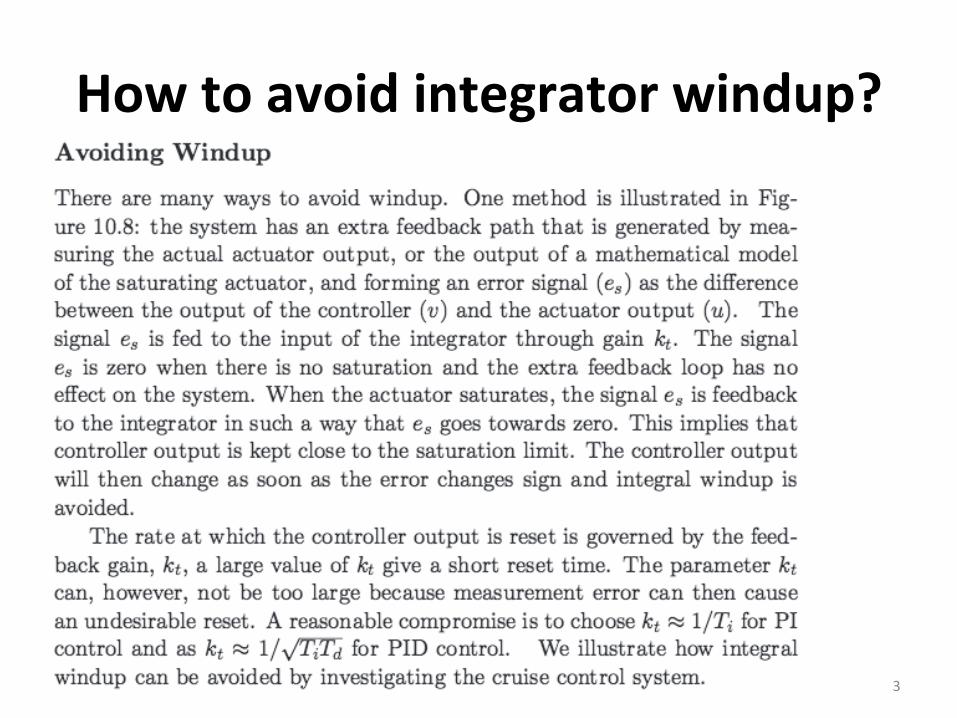
How to avoid integrator windup?
• asdf
3

Avoiding windup (1)
Ania Bae*ca, CDS Caltech 4
Avoiding windup (2) • Back-‐calcula*on: Use feedback of the difference between the desired (v) and the
actual control (u) as input for the integral term
• If v is not saturated, then set u = v • If v is at the satura*on value, then set u = satura*on value -‐> the process is in open
loop
• The error signal es= u – v. It is non-‐zero only when the actuator is saturated => no effect on normal opera*on.
• The normal feedback path around process is broken and a new feedback path around the integrator is formed. The integrator input becomes: es/kt + e*k/ki
• The integrator input is 0 at steady state. The transfer func*on between it and the error is s/(s+kt).
• The rule of thumb for choosing kt is that it be smaller than 1/ki, so that the integrator resets slower than integra*on.
• Back-‐calcula*ng never allows the input to the actuator to reach its actual satura*on level because it forecasts what will actually go into the actuator model beforehand.
Ania Bae*ca, CDS Caltech 5
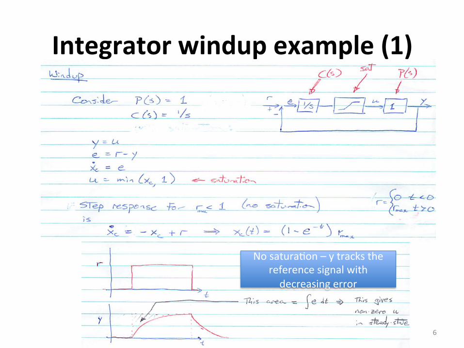
Integrator windup example (1)
No satura*on – y tracks the reference signal with decreasing error
6

Integrator windup example (2)
• adsf
linear
exponen*al
Case rmax > 1
y can’t track rmax => non-‐zero steady state
error due to satura*on effects
Ania Bae*ca, CDS Caltech 7
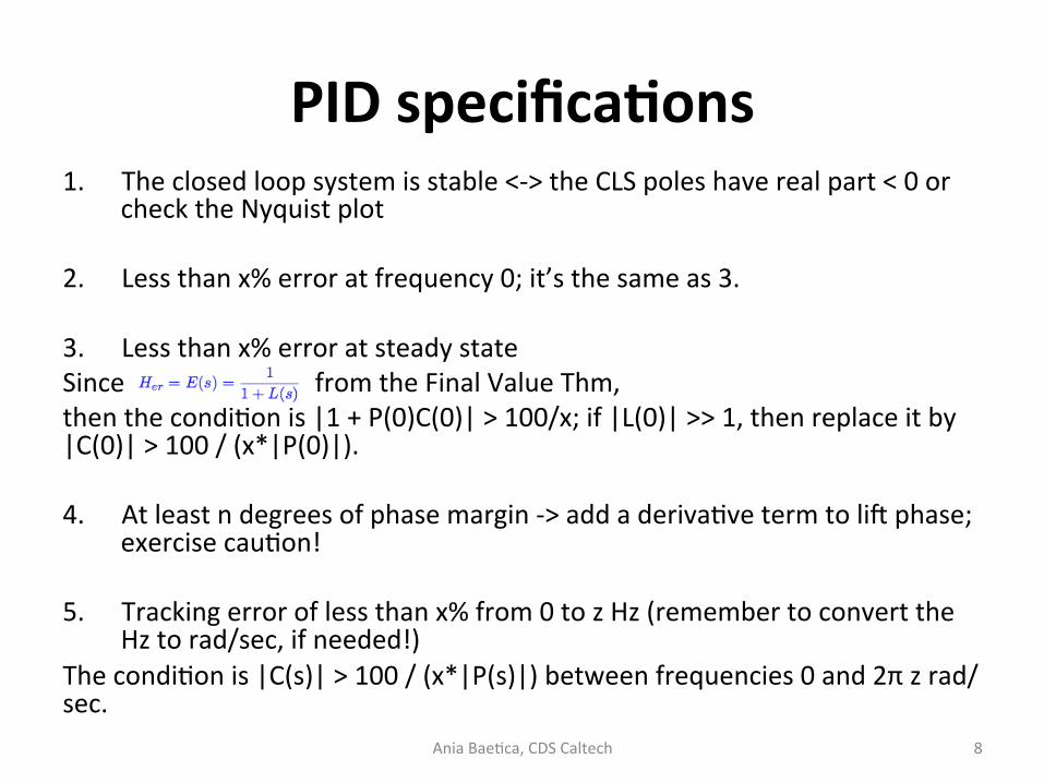
PID specificaAons 1. The closed loop system is stable <-‐> the CLS poles have real part < 0 or
check the Nyquist plot
2. Less than x% error at frequency 0; it’s the same as 3.
3. Less than x% error at steady state Since from the Final Value Thm, then the condi*on is |1 + P(0)C(0)| > 100/x; if |L(0)| >> 1, then replace it by |C(0)| > 100 / (x*|P(0)|). 4. At least n degrees of phase margin -‐> add a deriva*ve term to lig phase;
exercise cau*on!
5. Tracking error of less than x% from 0 to z Hz (remember to convert the Hz to rad/sec, if needed!)
The condi*on is |C(s)| > 100 / (x*|P(s)|) between frequencies 0 and 2π z rad/sec. Ania Bae*ca, CDS Caltech 8

Other possible PID specificaAons • Bandwidth (frequency at which the closed loop system is = ½) is at
least z ~ the frequency at which |L(s)| ~ 1, so then find s > z such that |C(s)|~ 1/|P(s)|
• Step response specifica*ons on overshoot, seKling *me, rise *me.
Ania Bae*ca, CDS Caltech 9

PID controller design (1)
• We have a plant P(s) = 1 / (ms2 + bs + c), m = 1000, b = 50, c = 10.
• We want to design a controller such that: 1. The steady state error is <= 2% 2. The tracking error is less than 10% between 0
and 1 rad/sec 3. The phase margin is >= 30 degrees
Ania Bae*ca, CDS Caltech 10
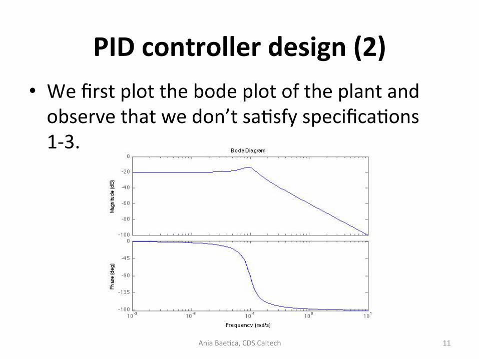
PID controller design (2) • We first plot the bode plot of the plant and observe that we don’t sa*sfy specifica*ons 1-‐3.
Ania Bae*ca, CDS Caltech 11

PID controller design (3) • We first think of adding a propor*onal controller to lig the graph so that |L(s)| > 10 between 0 and 1 rad/sec. We pick gain kp = 100.
• Then we try to set steady state error to 0 (it’s the easiest way), so we include an integral term ki = 1.
• Finally, our phase margin is really bad to begin with, so we add a deriva*ve term kd = 10 (ager tuning for the right phase margin).
Ania Bae*ca, CDS Caltech 12

PID controller design (4) • The controller we have now is C(s) = 100 + 1/s + 10s. • This is the open loop bode plot:
• We observe that we sa*sfy specifica*ons 1-‐3. It has phase margin 340. • Comment: the frequency we compute the phase margin at should be the
gain crossover. The freq marked on the plot is close enough.
Ania Bae*ca, CDS Caltech 13

PID controller design (5) • Always plot the step response of the closed loop system to see whether
you are stable and if the step response behaves reasonably (e.g.: doesn’t have large overshoot, poor seKling *me). Alterna*vely, you might also be required to sa*sfy step response specifica*ons, case in which more tuning might be necessary.
Ania Bae*ca, CDS Caltech 14
PID controller design references
hKp://ctms.engin.umich.edu/CTMS/index.php?example=CruiseControl&sec*on=ControlPID -‐> explains how to tune PID under step response specifica*ons hKp://ctms.engin.umich.edu/CTMS/index.php?example=Introduc*on&sec*on=ControlPID#10 -‐> check out their website for PID control
Ania Bae*ca, CDS Caltech 15

Windup references • hKps://controls.engin.umich.edu/wiki/index.php/PIDDownsides#Windup (windup)
• hKps://jagger.berkeley.edu/~pack/me132/Sec*on15.pdf (windup with min and max satura*on)
• hKp://cse.lab.imtlucca.it/~bemporad/teaching/ac/pdf/AC2-‐09-‐An*Windup.pdf (other an*-‐windup schemes)
Ania Bae*ca, CDS Caltech 16


