Intel® 64 and IA-32 Architectures Software Developer’s Manual Volume 1: Basic Architecture NOTE: The Intel® 64 and IA-32 Architectures Software Developer's Manual consists of five volumes: Basic Architecture, Order Number 253665; Instruction Set Reference A-M, Order Number 253666; Instruction Set Reference N-Z, Order Number 253667; System Programming Guide, Part 1, Order Number 253668; System Programming Guide, Part 2, Order Number 253669. Refer to all five volumes when evaluating your design needs. Order Number: 253665-034US March 2010
Transcript
Intel® 64 and IA-32 ArchitecturesSoftware Developer’s Manual
Volume 1:Basic Architecture
NOTE: The Intel® 64 and IA-32 Architectures Software Developer'sManual consists of five volumes: Basic Architecture, Order Number253665; Instruction Set Reference A-M, Order Number 253666;Instruction Set Reference N-Z, Order Number 253667; SystemProgramming Guide, Part 1, Order Number 253668; System ProgrammingGuide, Part 2, Order Number 253669. Refer to all five volumes whenevaluating your design needs.
Order Number: 253665-034US March 2010
CHAPTER 3BASIC EXECUTION ENVIRONMENT
This chapter describes the basic execution environment of an Intel 64 or IA-32 processor as seen by assembly-language programmers. It describes how the processor executes instructions and how it stores and manipulates data. The execu-tion environment described here includes memory (the address space), general-purpose data registers, segment registers, the flag register, and the instruction pointer register.
3.1 MODES OF OPERATIONThe IA-32 architecture supports three basic operating modes: protected mode, real-address mode, and system management mode. The operating mode determines which instructions and architectural features are accessible:
• Protected mode — This mode is the native state of the processor. Among the capabilities of protected mode is the ability to directly execute “real-address mode” 8086 software in a protected, multi-tasking environment. This feature is called virtual-8086 mode, although it is not actually a processor mode. Virtual-8086 mode is actually a protected mode attribute that can be enabled for any task.
• Real-address mode — This mode implements the programming environment of the Intel 8086 processor with extensions (such as the ability to switch to protected or system management mode). The processor is placed in real-address mode following power-up or a reset.
• System management mode (SMM) — This mode provides an operating system or executive with a transparent mechanism for implementing platform-specific functions such as power management and system security. The processor enters SMM when the external SMM interrupt pin (SMI#) is activated or an SMI is received from the advanced programmable interrupt controller (APIC).
In SMM, the processor switches to a separate address space while saving the basic context of the currently running program or task. SMM-specific code may then be executed transparently. Upon returning from SMM, the processor is placed back into its state prior to the system management interrupt. SMM was introduced with the Intel386™ SL and Intel486™ SL processors and became a standard IA-32 feature with the Pentium processor family.
Vol. 1 3-1
BASIC EXECUTION ENVIRONMENT
3.1.1 Intel® 64 ArchitectureIntel 64 architecture adds IA-32e mode. IA-32e mode has two sub-modes.These are:
• Compatibility mode (sub-mode of IA-32e mode) — Compatibility mode permits most legacy 16-bit and 32-bit applications to run without re-compilation under a 64-bit operating system. For brevity, the compatibility sub-mode is referred to as compatibility mode in IA-32 architecture. The execution environment of compatibility mode is the same as described in Section 3.2. Compatibility mode also supports all of the privilege levels that are supported in 64-bit and protected modes. Legacy applications that run in Virtual 8086 mode or use hardware task management will not work in this mode.
Compatibility mode is enabled by the operating system (OS) on a code segment basis. This means that a single 64-bit OS can support 64-bit applications running in 64-bit mode and support legacy 32-bit applications (not recompiled for 64-bits) running in compatibility mode.
Compatibility mode is similar to 32-bit protected mode. Applications access only the first 4 GByte of linear-address space. Compatibility mode uses 16-bit and 32-bit address and operand sizes. Like protected mode, this mode allows applica-tions to access physical memory greater than 4 GByte using PAE (Physical Address Extensions).
• 64-bit mode (sub-mode of IA-32e mode) — This mode enables a 64-bit operating system to run applications written to access 64-bit linear address space. For brevity, the 64-bit sub-mode is referred to as 64-bit mode in IA-32 architecture.
64-bit mode extends the number of general purpose registers and SIMD extension registers from 8 to 16. General purpose registers are widened to 64 bits. The mode also introduces a new opcode prefix (REX) to access the register extensions. See Section 3.2.1 for a detailed description.
64-bit mode is enabled by the operating system on a code-segment basis. Its default address size is 64 bits and its default operand size is 32 bits. The default operand size can be overridden on an instruction-by-instruction basis using a REX opcode prefix in conjunction with an operand size override prefix.
REX prefixes allow a 64-bit operand to be specified when operating in 64-bit mode. By using this mechanism, many existing instructions have been promoted to allow the use of 64-bit registers and 64-bit addresses.
3.2 OVERVIEW OF THE BASIC EXECUTION ENVIRONMENT
Any program or task running on an IA-32 processor is given a set of resources for executing instructions and for storing code, data, and state information. These
3-2 Vol. 1
BASIC EXECUTION ENVIRONMENT
resources (described briefly in the following paragraphs and shown in Figure 3-1) make up the basic execution environment for an IA-32 processor.
An Intel 64 processor supports the basic execution environment of an IA-32 processor, and a similar environment under IA-32e mode that can execute 64-bit programs (64-bit sub-mode) and 32-bit programs (compatibility sub-mode).
The basic execution environment is used jointly by the application programs and the operating system or executive running on the processor.
• Address space — Any task or program running on an IA-32 processor can address a linear address space of up to 4 GBytes (232 bytes) and a physical address space of up to 64 GBytes (236 bytes). See Section 3.3.6, “Extended Physical Addressing in Protected Mode,” for more information about addressing an address space greater than 4 GBytes.
• Basic program execution registers — The eight general-purpose registers, the six segment registers, the EFLAGS register, and the EIP (instruction pointer) register comprise a basic execution environment in which to execute a set of general-purpose instructions. These instructions perform basic integer arithmetic on byte, word, and doubleword integers, handle program flow control, operate on bit and byte strings, and address memory. See Section 3.4, “Basic Program Execution Registers,” for more information about these registers.
• x87 FPU registers — The eight x87 FPU data registers, the x87 FPU control register, the status register, the x87 FPU instruction pointer register, the x87 FPU operand (data) pointer register, the x87 FPU tag register, and the x87 FPU opcode register provide an execution environment for operating on single-precision, double-precision, and double extended-precision floating-point values, word integers, doubleword integers, quadword integers, and binary coded decimal (BCD) values. See Section 8.1, “x87 FPU Execution Environment,” for more information about these registers.
• MMX registers — The eight MMX registers support execution of single-instruction, multiple-data (SIMD) operations on 64-bit packed byte, word, and doubleword integers. See Section 9.2, “The MMX Technology Programming Environment,” for more information about these registers.
• XMM registers — The eight XMM data registers and the MXCSR register support execution of SIMD operations on 128-bit packed single-precision and double-precision floating-point values and on 128-bit packed byte, word, doubleword, and quadword integers. See Section 10.2, “SSE Programming Environment,” for more information about these registers.
Vol. 1 3-3
BASIC EXECUTION ENVIRONMENT
Figure 3-1. IA-32 Basic Execution Environment for Non-64-bit Modes
0
2^32 -1
Eight 32-bit
32-bits
32-bits
General-Purpose Registers
Segment Registers
EFLAGS Register
EIP (Instruction Pointer Register)
Address Space*
*The address space can be
Six 16-bitRegisters
Registers
Eight 80-bitRegisters
Floating-PointData Registers
Eight 64-bitRegisters MMX Registers
flat or segmented. Using
XMM RegistersEight 128-bitRegisters
16 bits Control Register
16 bits Status Register
48 bits FPU Instruction Pointer Register
48 bits FPU Data (Operand) Pointer Register
FPU Registers
MMX Registers
XMM Registers
32-bits MXCSR Register
Opcode Register (11-bits)
Basic Program Execution Registers
16 bits Tag Register
the physical addressextension mechanism, aphysical address space of2^36 - 1 can be addressed.
3-4 Vol. 1
BASIC EXECUTION ENVIRONMENT
• Stack — To support procedure or subroutine calls and the passing of parameters between procedures or subroutines, a stack and stack management resources are included in the execution environment. The stack (not shown in Figure 3-1) is located in memory. See Section 6.2, “Stacks,” for more information about stack structure.
In addition to the resources provided in the basic execution environment, the IA-32 architecture provides the following resources as part of its system-level architecture. They provide extensive support for operating-system and system-development soft-ware. Except for the I/O ports, the system resources are described in detail in the Intel® 64 and IA-32 Architectures Software Developer’s Manual, Volumes 3A & 3B.
• I/O ports — The IA-32 architecture supports a transfers of data to and from input/output (I/O) ports. See Chapter 13, “Input/Output,” in this volume.
• Control registers — The five control registers (CR0 through CR4) determine the operating mode of the processor and the characteristics of the currently executing task. See Chapter 2, “System Architecture Overview,” in the Intel® 64 and IA-32 Architectures Software Developer’s Manual, Volume 3A.
• Memory management registers — The GDTR, IDTR, task register, and LDTR specify the locations of data structures used in protected mode memory management. See Chapter 2, “System Architecture Overview,” in the Intel® 64 and IA-32 Architectures Software Developer’s Manual, Volume 3A.
• Debug registers — The debug registers (DR0 through DR7) control and allow monitoring of the processor’s debugging operations. See in the Intel® 64 and IA-32 Architectures Software Developer’s Manual, Volume 3B.
• Memory type range registers (MTRRs) — The MTRRs are used to assign memory types to regions of memory. See the sections on MTRRs in the Intel® 64 and IA-32 Architectures Software Developer’s Manual, Volumes 3A & 3B.
• Machine specific registers (MSRs) — The processor provides a variety of machine specific registers that are used to control and report on processor performance. Virtually all MSRs handle system related functions and are not accessible to an application program. One exception to this rule is the time-stamp counter. The MSRs are described in Appendix B, “Model-Specific Registers (MSRs),” of the Intel® 64 and IA-32 Architectures Software Developer’s Manual, Volume 3B.
• Machine check registers — The machine check registers consist of a set of control, status, and error-reporting MSRs that are used to detect and report on hardware (machine) errors. See Chapter 15, “Machine-Check Architecture,” of the Intel® 64 and IA-32 Architectures Software Developer’s Manual, Volume 3A.
• Performance monitoring counters — The performance monitoring counters allow processor performance events to be monitored. See Chapter 20, “Intro-duction to Virtual-Machine Extensions,” in the Intel® 64 and IA-32 Architectures Software Developer’s Manual, Volume 3B.
The remainder of this chapter describes the organization of memory and the address space, the basic program execution registers, and addressing modes. Refer to the
Vol. 1 3-5
BASIC EXECUTION ENVIRONMENT
following chapters in this volume for descriptions of the other program execution resources shown in Figure 3-1:
• x87 FPU registers — See Chapter 8, “Programming with the x87 FPU.”
• MMX Registers — See Chapter 9, “Programming with Intel® MMX™ Technology.”
• XMM registers — See Chapter 10, “Programming with Streaming SIMD Extensions (SSE),” Chapter 11, “Programming with Streaming SIMD Extensions 2 (SSE2),” and Chapter 12, “Programming with SSE3, SSSE3, SSE4 and AESNI.”
• Stack implementation and procedure calls — See Chapter 6, “Procedure Calls, Interrupts, and Exceptions.”
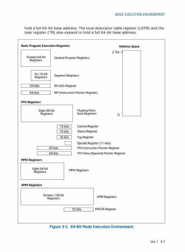
3.2.1 64-Bit Mode Execution EnvironmentThe execution environment for 64-bit mode is similar to that described in Section 3.2. The following paragraphs describe the differences that apply.
• Address space — A task or program running in 64-bit mode on an IA-32 processor can address linear address space of up to 264 bytes (subject to the canonical addressing requirement described in Section 3.3.7.1) and physical address space of up to 240 bytes. Software can query CPUID for the physical address size supported by a processor.
• Basic program execution registers — The number of general-purpose registers (GPRs) available is 16. GPRs are 64-bits wide and they support operations on byte, word, doubleword and quadword integers. Accessing byte registers is done uniformly to the lowest 8 bits. The instruction pointer register becomes 64 bits. The EFLAGS register is extended to 64 bits wide, and is referred to as the RFLAGS register. The upper 32 bits of RFLAGS is reserved. The lower 32 bits of RFLAGS is the same as EFLAGS. See Figure 3-2.
• XMM registers — There are 16 XMM data registers for SIMD operations. See Section 10.2, “SSE Programming Environment,” for more information about these registers.
• Stack — The stack pointer size is 64 bits. Stack size is not controlled by a bit in the SS descriptor (as it is in non-64-bit modes) nor can the pointer size be overridden by an instruction prefix.
• Control registers — Control registers expand to 64 bits. A new control register (the task priority register: CR8 or TPR) has been added. See Chapter 2, “Intel® 64 and IA-32 Architectures,” in this volume.
• Debug registers — Debug registers expand to 64 bits. See Chapter 16, “Debugging, Branch Profiles and Time-Stamp Counter,” in the Intel® 64 and IA-32 Architectures Software Developer’s Manual, Volume 3A.
• Descriptor table registers — The global descriptor table register (GDTR) and interrupt descriptor table register (IDTR) expand to 10 bytes so that they can
3-6 Vol. 1
BASIC EXECUTION ENVIRONMENT
hold a full 64-bit base address. The local descriptor table register (LDTR) and the task register (TR) also expand to hold a full 64-bit base address.
Figure 3-2. 64-Bit Mode Execution Environment
0
2^64 -1
Sixteen 64-bit
64-bits
64-bits
General-Purpose Registers
Segment Registers
RFLAGS Register
RIP (Instruction Pointer Register)
Address Space
Six 16-bitRegisters
Registers
Eight 80-bitRegisters
Floating-PointData Registers
Eight 64-bitRegisters MMX Registers
XMM RegistersSixteen 128-bitRegisters
16 bits Control Register
16 bits Status Register
64 bits FPU Instruction Pointer Register
64 bits FPU Data (Operand) Pointer Register
FPU Registers
MMX Registers
XMM Registers
32-bits MXCSR Register
Opcode Register (11-bits)
Basic Program Execution Registers
16 bits Tag Register
Vol. 1 3-7
BASIC EXECUTION ENVIRONMENT
3.3 MEMORY ORGANIZATIONThe memory that the processor addresses on its bus is called physical memory. Physical memory is organized as a sequence of 8-bit bytes. Each byte is assigned a unique address, called a physical address. The physical address space ranges from zero to a maximum of 236 − 1 (64 GBytes) if the processor does not support Intel 64 architecture. Intel 64 architecture introduces a changes in physical and linear address space; these are described in Section 3.3.3, Section 3.3.4, and Section 3.3.7.
Virtually any operating system or executive designed to work with an IA-32 or Intel 64 processor will use the processor’s memory management facilities to access memory. These facilities provide features such as segmentation and paging, which allow memory to be managed efficiently and reliably. Memory management is described in detail in Chapter 3, “Protected-Mode Memory Management,” in the Intel® 64 and IA-32 Architectures Software Developer’s Manual, Volume 3A. The following paragraphs describe the basic methods of addressing memory when memory management is used.
3.3.1 IA-32 Memory ModelsWhen employing the processor’s memory management facilities, programs do not directly address physical memory. Instead, they access memory using one of three memory models: flat, segmented, or real address mode:
• Flat memory model — Memory appears to a program as a single, continuous address space (Figure 3-3). This space is called a linear address space. Code, data, and stacks are all contained in this address space. Linear address space is byte addressable, with addresses running contiguously from 0 to 232 - 1 (if not in 64-bit mode). An address for any byte in linear address space is called a linear address.
• Segmented memory model — Memory appears to a program as a group of independent address spaces called segments. Code, data, and stacks are typically contained in separate segments. To address a byte in a segment, a program issues a logical address. This consists of a segment selector and an offset (logical addresses are often referred to as far pointers). The segment selector identifies the segment to be accessed and the offset identifies a byte in the address space of the segment. Programs running on an IA-32 processor can address up to 16,383 segments of different sizes and types, and each segment can be as large as 232 bytes.
Internally, all the segments that are defined for a system are mapped into the processor’s linear address space. To access a memory location, the processor thus translates each logical address into a linear address. This translation is transparent to the application program.
The primary reason for using segmented memory is to increase the reliability of programs and systems. For example, placing a program’s stack in a separate
3-8 Vol. 1
BASIC EXECUTION ENVIRONMENT
segment prevents the stack from growing into the code or data space and overwriting instructions or data, respectively.
• Real-address mode memory model — This is the memory model for the Intel 8086 processor. It is supported to provide compatibility with existing programs written to run on the Intel 8086 processor. The real-address mode uses a specific implementation of segmented memory in which the linear address space for the program and the operating system/executive consists of an array of segments of up to 64 KBytes in size each. The maximum size of the linear address space in real-address mode is 220 bytes.
See also: Chapter 17, “8086 Emulation,” Intel® 64 and IA-32 Architectures Software Developer’s Manual, Volume 3A.
Figure 3-3. Three Memory Management Models
Linear Address
Flat Model
LinearAddressSpace*
Segment Selector
Offset
Segment Selector
Segmented Model
Real-Address Mode Model
Linear Address
Logical
Offset (effective address)
Space DividedInto Equal
Sized Segments
Address
LogicalAddress
LinearAddress
Space*
Segments
* The linear address spacecan be paged when using the flat or segmented model.
Vol. 1 3-9
BASIC EXECUTION ENVIRONMENT
3.3.2 Paging and Virtual MemoryWith the flat or the segmented memory model, linear address space is mapped into the processor’s physical address space either directly or through paging. When using direct mapping (paging disabled), each linear address has a one-to-one correspon-dence with a physical address. Linear addresses are sent out on the processor’s address lines without translation.
When using the IA-32 architecture’s paging mechanism (paging enabled), linear address space is divided into pages which are mapped to virtual memory. The pages of virtual memory are then mapped as needed into physical memory. When an oper-ating system or executive uses paging, the paging mechanism is transparent to an application program. All that the application sees is linear address space.
In addition, IA-32 architecture’s paging mechanism includes extensions that support:
• Page Address Extensions (PAE) to address physical address space greater than 4 GBytes.
• Page Size Extensions (PSE) to map linear address to physical address in 4-MBytes pages.
See also: Chapter 3, “Protected-Mode Memory Management,” in the Intel® 64 and IA-32 Architectures Software Developer’s Manual, Volume 3A.
3.3.3 Memory Organization in 64-Bit ModeIntel 64 architecture supports physical address space greater than 64 GBytes; the actual physical address size of IA-32 processors is implementation specific. In 64-bit mode, there is architectural support for 64-bit linear address space. However, processors supporting Intel 64 architecture may implement less than 64-bits (see Section 3.3.7.1). The linear address space is mapped into the processor physical address space through the PAE paging mechanism.
3.3.4 Modes of Operation vs. Memory ModelWhen writing code for an IA-32 or Intel 64 processor, a programmer needs to know the operating mode the processor is going to be in when executing the code and the memory model being used. The relationship between operating modes and memory models is as follows:
• Protected mode — When in protected mode, the processor can use any of the memory models described in this section. (The real-addressing mode memory model is ordinarily used only when the processor is in the virtual-8086 mode.) The memory model used depends on the design of the operating system or executive. When multitasking is implemented, individual tasks can use different memory models.
3-10 Vol. 1
BASIC EXECUTION ENVIRONMENT
• Real-address mode — When in real-address mode, the processor only supports the real-address mode memory model.
• System management mode — When in SMM, the processor switches to a separate address space, called the system management RAM (SMRAM). The memory model used to address bytes in this address space is similar to the real-address mode model. See Chapter 26, “System Management,” in the Intel® 64 and IA-32 Architectures Software Developer’s Manual, Volume 3B, for more information on the memory model used in SMM.
• Compatibility mode — Software that needs to run in compatibility mode should observe the same memory model as those targeted to run in 32-bit protected mode. The effect of segmentation is the same as it is in 32-bit protected mode semantics.
• 64-bit mode — Segmentation is generally (but not completely) disabled, creating a flat 64-bit linear-address space. Specifically, the processor treats the segment base of CS, DS, ES, and SS as zero in 64-bit mode (this makes a linear address equal an effective address). Segmented and real address modes are not available in 64-bit mode.
3.3.5 32-Bit and 16-Bit Address and Operand SizesIA-32 processors in protected mode can be configured for 32-bit or 16-bit address and operand sizes. With 32-bit address and operand sizes, the maximum linear address or segment offset is FFFFFFFFH (232-1); operand sizes are typically 8 bits or 32 bits. With 16-bit address and operand sizes, the maximum linear address or segment offset is FFFFH (216-1); operand sizes are typically 8 bits or 16 bits.
When using 32-bit addressing, a logical address (or far pointer) consists of a 16-bit segment selector and a 32-bit offset; when using 16-bit addressing, an address consists of a 16-bit segment selector and a 16-bit offset.
Instruction prefixes allow temporary overrides of the default address and/or operand sizes from within a program.
When operating in protected mode, the segment descriptor for the currently executing code segment defines the default address and operand size. A segment descriptor is a system data structure not normally visible to application code. Assem-bler directives allow the default addressing and operand size to be chosen for a program. The assembler and other tools then set up the segment descriptor for the code segment appropriately.
When operating in real-address mode, the default addressing and operand size is 16 bits. An address-size override can be used in real-address mode to enable 32-bit addressing. However, the maximum allowable 32-bit linear address is still 000FFFFFH (220-1).
Vol. 1 3-11
BASIC EXECUTION ENVIRONMENT
3.3.6 Extended Physical Addressing in Protected ModeBeginning with P6 family processors, the IA-32 architecture supports addressing of up to 64 GBytes (236 bytes) of physical memory. A program or task could not address locations in this address space directly. Instead, it addresses individual linear address spaces of up to 4 GBytes that mapped to 64-GByte physical address space through a virtual memory management mechanism. Using this mechanism, an oper-ating system can enable a program to switch 4-GByte linear address spaces within 64-GByte physical address space.
The use of extended physical addressing requires the processor to operate in protected mode and the operating system to provide a virtual memory management system. See “36-Bit Physical Addressing Using the PAE Paging Mechanism” in Chapter 3, “Protected-Mode Memory Management,” of the Intel® 64 and IA-32 Architectures Software Developer’s Manual, Volume 3A.
3.3.7 Address Calculations in 64-Bit ModeIn most cases, 64-bit mode uses flat address space for code, data, and stacks. In 64-bit mode (if there is no address-size override), the size of effective address calcu-lations is 64 bits. An effective-address calculation uses a 64-bit base and index regis-ters and sign-extend displacements to 64 bits.
In the flat address space of 64-bit mode, linear addresses are equal to effective addresses because the base address is zero. In the event that FS or GS segments are used with a non-zero base, this rule does not hold. In 64-bit mode, the effective address components are added and the effective address is truncated (See for example the instruction LEA) before adding the full 64-bit segment base. The base is never truncated, regardless of addressing mode in 64-bit mode.
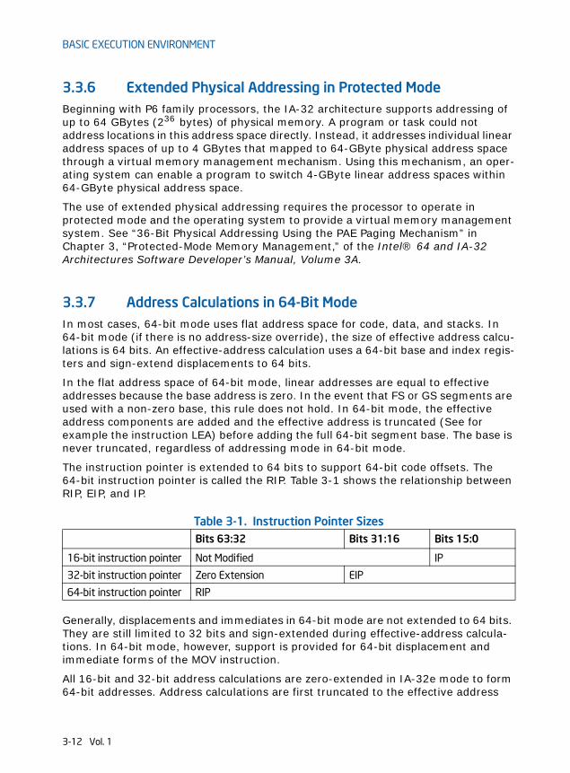
The instruction pointer is extended to 64 bits to support 64-bit code offsets. The 64-bit instruction pointer is called the RIP. Table 3-1 shows the relationship between RIP, EIP, and IP.
Table 3-1. Instruction Pointer Sizes
Generally, displacements and immediates in 64-bit mode are not extended to 64 bits. They are still limited to 32 bits and sign-extended during effective-address calcula-tions. In 64-bit mode, however, support is provided for 64-bit displacement and immediate forms of the MOV instruction.
All 16-bit and 32-bit address calculations are zero-extended in IA-32e mode to form 64-bit addresses. Address calculations are first truncated to the effective address
Bits 63:32 Bits 31:16 Bits 15:0
16-bit instruction pointer Not Modified IP
32-bit instruction pointer Zero Extension EIP
64-bit instruction pointer RIP
3-12 Vol. 1
BASIC EXECUTION ENVIRONMENT
size of the current mode (64-bit mode or compatibility mode), as overridden by any address-size prefix. The result is then zero-extended to the full 64-bit address width. Because of this, 16-bit and 32-bit applications running in compatibility mode can access only the low 4 GBytes of the 64-bit mode effective addresses. Likewise, a 32-bit address generated in 64-bit mode can access only the low 4 GBytes of the 64-bit mode effective addresses.
3.3.7.1 Canonical AddressingIn 64-bit mode, an address is considered to be in canonical form if address bits 63 through to the most-significant implemented bit by the microarchitecture are set to either all ones or all zeros.
Intel 64 architecture defines a 64-bit linear address. Implementations can support less. The first implementation of IA-32 processors with Intel 64 architecture supports a 48-bit linear address. This means a canonical address must have bits 63 through 48 set to zeros or ones (depending on whether bit 47 is a zero or one).
Although implementations may not use all 64 bits of the linear address, they should check bits 63 through the most-significant implemented bit to see if the address is in canonical form. If a linear-memory reference is not in canonical form, the implemen-tation should generate an exception. In most cases, a general-protection exception (#GP) is generated. However, in the case of explicit or implied stack references, a stack fault (#SS) is generated.
Instructions that have implied stack references, by default, use the SS segment register. These include PUSH/POP-related instructions and instructions using RSP/RBP as base registers. In these cases, the canonical fault is #SF.
If an instruction uses base registers RSP/RBP and uses a segment override prefix to specify a non-SS segment, a canonical fault generates a #GP (instead of an #SF). In 64-bit mode, only FS and GS segment-overrides are applicable in this situation. Other segment override prefixes (CS, DS, ES and SS) are ignored. Note that this also means that an SS segment-override applied to a “non-stack” register reference is ignored. Such a sequence still produces a #GP for a canonical fault (and not an #SF).
3.4 BASIC PROGRAM EXECUTION REGISTERSIA-32 architecture provides 16 basic program execution registers for use in general system and application programing (see Figure 3-4). These registers can be grouped as follows:
• General-purpose registers. These eight registers are available for storing operands and pointers.
• Segment registers. These registers hold up to six segment selectors.
Vol. 1 3-13
BASIC EXECUTION ENVIRONMENT
• EFLAGS (program status and control) register. The EFLAGS register report on the status of the program being executed and allows limited (application-program level) control of the processor.
• EIP (instruction pointer) register. The EIP register contains a 32-bit pointer to the next instruction to be executed.
3.4.1 General-Purpose RegistersThe 32-bit general-purpose registers EAX, EBX, ECX, EDX, ESI, EDI, EBP, and ESP are provided for holding the following items:
• Operands for logical and arithmetic operations
• Operands for address calculations
• Memory pointers
Although all of these registers are available for general storage of operands, results, and pointers, caution should be used when referencing the ESP register. The ESP register holds the stack pointer and as a general rule should not be used for another purpose.
Many instructions assign specific registers to hold operands. For example, string instructions use the contents of the ECX, ESI, and EDI registers as operands. When using a segmented memory model, some instructions assume that pointers in certain registers are relative to specific segments. For instance, some instructions assume that a pointer in the EBX register points to a memory location in the DS segment.
3-14 Vol. 1
BASIC EXECUTION ENVIRONMENT
The special uses of general-purpose registers by instructions are described in Chapter 5, “Instruction Set Summary,” in this volume. See also: Chapter 3 and Chapter 4 of Intel® 64 and IA-32 Architectures Software Developer’s Manual, Volumes 2A & 2B. The following is a summary of special uses:
• EAX — Accumulator for operands and results data
• EBX — Pointer to data in the DS segment
• ECX — Counter for string and loop operations
• EDX — I/O pointer
• ESI — Pointer to data in the segment pointed to by the DS register; source pointer for string operations
• EDI — Pointer to data (or destination) in the segment pointed to by the ES register; destination pointer for string operations
• ESP — Stack pointer (in the SS segment)
Figure 3-4. General System and Application Programming Registers
031EAXEBXECX
EDXESI
EDIEBP
ESP
Segment Registers
CS
DSSS
ESFS
GS
015
031EFLAGS
EIP31 0
General-Purpose Registers
Program Status and Control Register
Instruction Pointer
Vol. 1 3-15
BASIC EXECUTION ENVIRONMENT
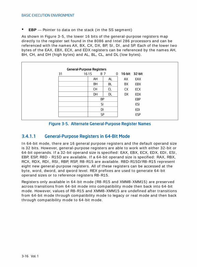
• EBP — Pointer to data on the stack (in the SS segment)
As shown in Figure 3-5, the lower 16 bits of the general-purpose registers map directly to the register set found in the 8086 and Intel 286 processors and can be referenced with the names AX, BX, CX, DX, BP, SI, DI, and SP. Each of the lower two bytes of the EAX, EBX, ECX, and EDX registers can be referenced by the names AH, BH, CH, and DH (high bytes) and AL, BL, CL, and DL (low bytes).
3.4.1.1 General-Purpose Registers in 64-Bit ModeIn 64-bit mode, there are 16 general purpose registers and the default operand size is 32 bits. However, general-purpose registers are able to work with either 32-bit or 64-bit operands. If a 32-bit operand size is specified: EAX, EBX, ECX, EDX, EDI, ESI, EBP, ESP, R8D - R15D are available. If a 64-bit operand size is specified: RAX, RBX, RCX, RDX, RDI, RSI, RBP, RSP, R8-R15 are available. R8D-R15D/R8-R15 represent eight new general-purpose registers. All of these registers can be accessed at the byte, word, dword, and qword level. REX prefixes are used to generate 64-bit operand sizes or to reference registers R8-R15.
Registers only available in 64-bit mode (R8-R15 and XMM8-XMM15) are preserved across transitions from 64-bit mode into compatibility mode then back into 64-bit mode. However, values of R8-R15 and XMM8-XMM15 are undefined after transitions from 64-bit mode through compatibility mode to legacy or real mode and then back through compatibility mode to 64-bit mode.
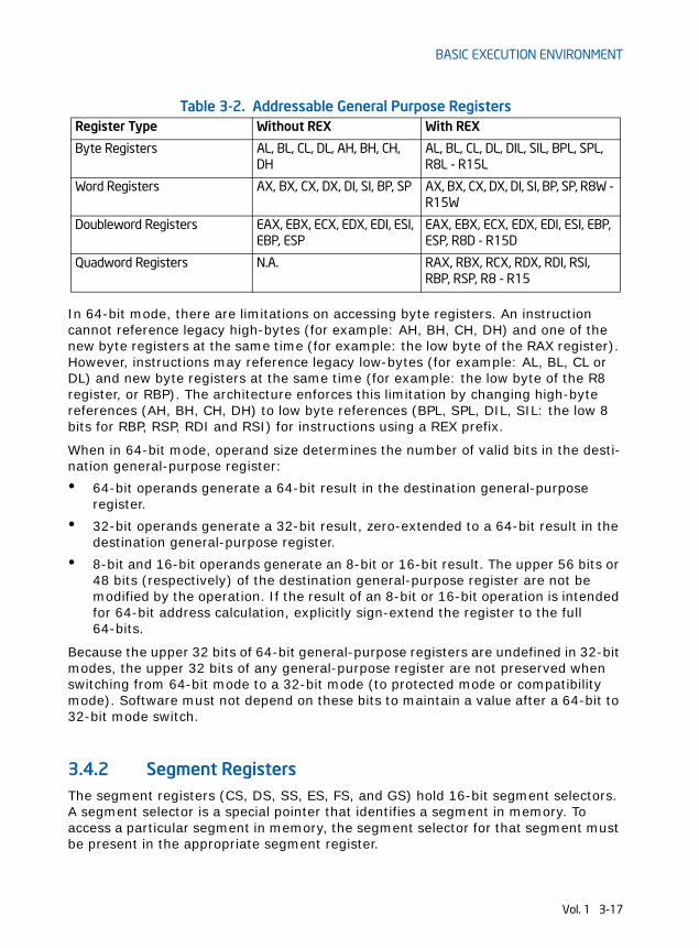
In 64-bit mode, there are limitations on accessing byte registers. An instruction cannot reference legacy high-bytes (for example: AH, BH, CH, DH) and one of the new byte registers at the same time (for example: the low byte of the RAX register). However, instructions may reference legacy low-bytes (for example: AL, BL, CL or DL) and new byte registers at the same time (for example: the low byte of the R8 register, or RBP). The architecture enforces this limitation by changing high-byte references (AH, BH, CH, DH) to low byte references (BPL, SPL, DIL, SIL: the low 8 bits for RBP, RSP, RDI and RSI) for instructions using a REX prefix.
When in 64-bit mode, operand size determines the number of valid bits in the desti-nation general-purpose register:
• 64-bit operands generate a 64-bit result in the destination general-purpose register.
• 32-bit operands generate a 32-bit result, zero-extended to a 64-bit result in the destination general-purpose register.
• 8-bit and 16-bit operands generate an 8-bit or 16-bit result. The upper 56 bits or 48 bits (respectively) of the destination general-purpose register are not be modified by the operation. If the result of an 8-bit or 16-bit operation is intended for 64-bit address calculation, explicitly sign-extend the register to the full 64-bits.
Because the upper 32 bits of 64-bit general-purpose registers are undefined in 32-bit modes, the upper 32 bits of any general-purpose register are not preserved when switching from 64-bit mode to a 32-bit mode (to protected mode or compatibility mode). Software must not depend on these bits to maintain a value after a 64-bit to 32-bit mode switch.
3.4.2 Segment RegistersThe segment registers (CS, DS, SS, ES, FS, and GS) hold 16-bit segment selectors. A segment selector is a special pointer that identifies a segment in memory. To access a particular segment in memory, the segment selector for that segment must be present in the appropriate segment register.
Table 3-2. Addressable General Purpose RegistersRegister Type Without REX With REX
When writing application code, programmers generally create segment selectors with assembler directives and symbols. The assembler and other tools then create the actual segment selector values associated with these directives and symbols. If writing system code, programmers may need to create segment selectors directly. See Chapter 3, “Protected-Mode Memory Management,” in the Intel® 64 and IA-32 Architectures Software Developer’s Manual, Volume 3A.
How segment registers are used depends on the type of memory management model that the operating system or executive is using. When using the flat (unsegmented) memory model, segment registers are loaded with segment selectors that point to overlapping segments, each of which begins at address 0 of the linear address space (see Figure 3-6). These overlapping segments then comprise the linear address space for the program. Typically, two overlapping segments are defined: one for code and another for data and stacks. The CS segment register points to the code segment and all the other segment registers point to the data and stack segment.
When using the segmented memory model, each segment register is ordinarily loaded with a different segment selector so that each segment register points to a different segment within the linear address space (see Figure 3-7). At any time, a program can thus access up to six segments in the linear address space. To access a segment not pointed to by one of the segment registers, a program must first load the segment selector for the segment to be accessed into a segment register.
Figure 3-6. Use of Segment Registers for Flat Memory Model
Segment Registers
CS
SSDS
ESFSGS
Linear AddressSpace for Program
The segment selector ineach segment registerpoints to an overlapping
OverlappingSegments
of up to4 GBytes
segment in the linearaddress space.
Beginning atAddress 0
3-18 Vol. 1
BASIC EXECUTION ENVIRONMENT
Each of the segment registers is associated with one of three types of storage: code, data, or stack. For example, the CS register contains the segment selector for the code segment, where the instructions being executed are stored. The processor fetches instructions from the code segment, using a logical address that consists of the segment selector in the CS register and the contents of the EIP register. The EIP register contains the offset within the code segment of the next instruction to be executed. The CS register cannot be loaded explicitly by an application program. Instead, it is loaded implicitly by instructions or internal processor operations that change program control (such as, procedure calls, interrupt handling, or task switching).
The DS, ES, FS, and GS registers point to four data segments. The availability of four data segments permits efficient and secure access to different types of data structures. For example, four separate data segments might be created: one for the data structures of the current module, another for the data exported from a higher-level module, a third for a dynamically created data structure, and a fourth for data shared with another program. To access additional data segments, the application program must load segment selectors for these segments into the DS, ES, FS, and GS registers, as needed.
The SS register contains the segment selector for the stack segment, where the procedure stack is stored for the program, task, or handler currently being executed. All stack operations use the SS register to find the stack segment. Unlike the CS register, the SS register can be loaded explicitly, which permits application programs to set up multiple stacks and switch among them.
Figure 3-7. Use of Segment Registers in Segmented Memory Model
Segment Registers
CSDSSSESFSGS
CodeSegment
DataSegment
StackSegment
DataSegment
DataSegment
DataSegment
All segmentsare mappedto the samelinear-addressspace
Vol. 1 3-19
BASIC EXECUTION ENVIRONMENT
See Section 3.3, “Memory Organization,” for an overview of how the segment regis-ters are used in real-address mode.
The four segment registers CS, DS, SS, and ES are the same as the segment regis-ters found in the Intel 8086 and Intel 286 processors and the FS and GS registers were introduced into the IA-32 Architecture with the Intel386™ family of processors.
3.4.2.1 Segment Registers in 64-Bit ModeIn 64-bit mode: CS, DS, ES, SS are treated as if each segment base is 0, regardless of the value of the associated segment descriptor base. This creates a flat address space for code, data, and stack. FS and GS are exceptions. Both segment registers may be used as additional base registers in linear address calculations (in the addressing of local data and certain operating system data structures).
Even though segmentation is generally disabled, segment register loads may cause the processor to perform segment access assists. During these activities, enabled processors will still perform most of the legacy checks on loaded values (even if the checks are not applicable in 64-bit mode). Such checks are needed because a segment register loaded in 64-bit mode may be used by an application running in compatibility mode.
Limit checks for CS, DS, ES, SS, FS, and GS are disabled in 64-bit mode.
3.4.3 EFLAGS RegisterThe 32-bit EFLAGS register contains a group of status flags, a control flag, and a group of system flags. Figure 3-8 defines the flags within this register. Following initialization of the processor (either by asserting the RESET pin or the INIT pin), the state of the EFLAGS register is 00000002H. Bits 1, 3, 5, 15, and 22 through 31 of this register are reserved. Software should not use or depend on the states of any of these bits.
Some of the flags in the EFLAGS register can be modified directly, using special-purpose instructions (described in the following sections). There are no instructions that allow the whole register to be examined or modified directly.
The following instructions can be used to move groups of flags to and from the proce-dure stack or the EAX register: LAHF, SAHF, PUSHF, PUSHFD, POPF, and POPFD. After the contents of the EFLAGS register have been transferred to the procedure stack or EAX register, the flags can be examined and modified using the processor’s bit manipulation instructions (BT, BTS, BTR, and BTC).
When suspending a task (using the processor’s multitasking facilities), the processor automatically saves the state of the EFLAGS register in the task state segment (TSS) for the task being suspended. When binding itself to a new task, the processor loads the EFLAGS register with data from the new task’s TSS.
When a call is made to an interrupt or exception handler procedure, the processor automatically saves the state of the EFLAGS registers on the procedure stack. When
3-20 Vol. 1
BASIC EXECUTION ENVIRONMENT
an interrupt or exception is handled with a task switch, the state of the EFLAGS register is saved in the TSS for the task being suspended.
As the IA-32 Architecture has evolved, flags have been added to the EFLAGS register, but the function and placement of existing flags have remained the same from one family of the IA-32 processors to the next. As a result, code that accesses or modifies these flags for one family of IA-32 processors works as expected when run on later families of processors.
3.4.3.1 Status FlagsThe status flags (bits 0, 2, 4, 6, 7, and 11) of the EFLAGS register indicate the results of arithmetic instructions, such as the ADD, SUB, MUL, and DIV instructions. The status flag functions are:
CF (bit 0) Carry flag — Set if an arithmetic operation generates a carry or a borrow out of the most-significant bit of the result; cleared
Figure 3-8. EFLAGS Register
31 2930 28 27 26 25 24 23 22 21 20 19 18 17 16
0 RF
ID
AC
VM
X Virtual-8086 Mode (VM)X Resume Flag (RF)X Nested Task (NT)X I/O Privilege Level (IOPL)S Overflow Flag (OF)C Direction Flag (DF)X Interrupt Enable Flag (IF)
X Alignment Check (AC)
X ID Flag (ID)X Virtual Interrupt Pending (VIP)
15 1314 12 11 10 9 8 7 6 5 4 3 2 1 0
0 CF
AF
PF 1D
FIF
TF
SF
ZF
NT 000 0 0 0 0 0 0 0 0
VIP
VIF
OF
IOPL
X Virtual Interrupt Flag (VIF)
X Trap Flag (TF)S Sign Flag (SF)S Zero Flag (ZF)S Auxiliary Carry Flag (AF)S Parity Flag (PF)S Carry Flag (CF)
S Indicates a Status FlagC Indicates a Control FlagX Indicates a System Flag
Reserved bit positions. DO NOT USE.Always set to values previously read.
Vol. 1 3-21
BASIC EXECUTION ENVIRONMENT
otherwise. This flag indicates an overflow condition for unsigned-integer arithmetic. It is also used in multiple-precision arithmetic.
PF (bit 2) Parity flag — Set if the least-significant byte of the result contains an even number of 1 bits; cleared otherwise.
AF (bit 4) Adjust flag — Set if an arithmetic operation generates a carry or a borrow out of bit 3 of the result; cleared otherwise. This flag is used in binary-coded decimal (BCD) arithmetic.
ZF (bit 6) Zero flag — Set if the result is zero; cleared otherwise.
SF (bit 7) Sign flag — Set equal to the most-significant bit of the result, which is the sign bit of a signed integer. (0 indicates a positive value and 1 indicates a negative value.)
OF (bit 11) Overflow flag — Set if the integer result is too large a positive number or too small a negative number (excluding the sign-bit) to fit in the destination operand; cleared otherwise. This flag indicates an overflow condition for signed-integer (two’s complement) arithmetic.
Of these status flags, only the CF flag can be modified directly, using the STC, CLC, and CMC instructions. Also the bit instructions (BT, BTS, BTR, and BTC) copy a spec-ified bit into the CF flag.
The status flags allow a single arithmetic operation to produce results for three different data types: unsigned integers, signed integers, and BCD integers. If the result of an arithmetic operation is treated as an unsigned integer, the CF flag indi-cates an out-of-range condition (carry or a borrow); if treated as a signed integer (two’s complement number), the OF flag indicates a carry or borrow; and if treated as a BCD digit, the AF flag indicates a carry or borrow. The SF flag indicates the sign of a signed integer. The ZF flag indicates either a signed- or an unsigned-integer zero.
When performing multiple-precision arithmetic on integers, the CF flag is used in conjunction with the add with carry (ADC) and subtract with borrow (SBB) instruc-tions to propagate a carry or borrow from one computation to the next.
The condition instructions Jcc (jump on condition code cc), SETcc (byte set on condi-tion code cc), LOOPcc, and CMOVcc (conditional move) use one or more of the status flags as condition codes and test them for branch, set-byte, or end-loop conditions.
3.4.3.2 DF FlagThe direction flag (DF, located in bit 10 of the EFLAGS register) controls string instructions (MOVS, CMPS, SCAS, LODS, and STOS). Setting the DF flag causes the string instructions to auto-decrement (to process strings from high addresses to low addresses). Clearing the DF flag causes the string instructions to auto-increment (process strings from low addresses to high addresses).
The STD and CLD instructions set and clear the DF flag, respectively.
3-22 Vol. 1
BASIC EXECUTION ENVIRONMENT
3.4.3.3 System Flags and IOPL FieldThe system flags and IOPL field in the EFLAGS register control operating-system or executive operations. They should not be modified by application programs. The functions of the system flags are as follows:
TF (bit 8) Trap flag — Set to enable single-step mode for debugging; clear to disable single-step mode.
IF (bit 9) Interrupt enable flag — Controls the response of the processor to maskable interrupt requests. Set to respond to maskable interrupts; cleared to inhibit maskable interrupts.
IOPL (bits 12 and 13)I/O privilege level field — Indicates the I/O privilege level of the currently running program or task. The current privilege level (CPL) of the currently running program or task must be less than or equal to the I/O privilege level to access the I/O address space. This field can only be modified by the POPF and IRET instructions when operating at a CPL of 0.
NT (bit 14) Nested task flag — Controls the chaining of interrupted and called tasks. Set when the current task is linked to the previ-ously executed task; cleared when the current task is not linked to another task.
RF (bit 16) Resume flag — Controls the processor’s response to debug exceptions.
VM (bit 17) Virtual-8086 mode flag — Set to enable virtual-8086 mode; clear to return to protected mode without virtual-8086 mode semantics.
AC (bit 18) Alignment check flag — Set this flag and the AM bit in the CR0 register to enable alignment checking of memory references; clear the AC flag and/or the AM bit to disable alignment checking.
VIF (bit 19) Virtual interrupt flag — Virtual image of the IF flag. Used in conjunction with the VIP flag. (To use this flag and the VIP flag the virtual mode extensions are enabled by setting the VME flag in control register CR4.)
VIP (bit 20) Virtual interrupt pending flag — Set to indicate that an inter-rupt is pending; clear when no interrupt is pending. (Software sets and clears this flag; the processor only reads it.) Used in conjunction with the VIF flag.
ID (bit 21) Identification flag — The ability of a program to set or clear this flag indicates support for the CPUID instruction.
For a detailed description of these flags: see Chapter 3, “Protected-Mode Memory Management,” in the Intel® 64 and IA-32 Architectures Software Developer’s Manual, Volume 3A.
Vol. 1 3-23
BASIC EXECUTION ENVIRONMENT
3.4.3.4 RFLAGS Register in 64-Bit ModeIn 64-bit mode, EFLAGS is extended to 64 bits and called RFLAGS. The upper 32 bits of RFLAGS register is reserved. The lower 32 bits of RFLAGS is the same as EFLAGS.
3.5 INSTRUCTION POINTERThe instruction pointer (EIP) register contains the offset in the current code segment for the next instruction to be executed. It is advanced from one instruction boundary to the next in straight-line code or it is moved ahead or backwards by a number of instructions when executing JMP, Jcc, CALL, RET, and IRET instructions.
The EIP register cannot be accessed directly by software; it is controlled implicitly by control-transfer instructions (such as JMP, Jcc, CALL, and RET), interrupts, and exceptions. The only way to read the EIP register is to execute a CALL instruction and then read the value of the return instruction pointer from the procedure stack. The EIP register can be loaded indirectly by modifying the value of a return instruction pointer on the procedure stack and executing a return instruction (RET or IRET). See Section 6.2.4.2, “Return Instruction Pointer.”
All IA-32 processors prefetch instructions. Because of instruction prefetching, an instruction address read from the bus during an instruction load does not match the value in the EIP register. Even though different processor generations use different prefetching mechanisms, the function of the EIP register to direct program flow remains fully compatible with all software written to run on IA-32 processors.
3.5.1 Instruction Pointer in 64-Bit ModeIn 64-bit mode, the RIP register becomes the instruction pointer. This register holds the 64-bit offset of the next instruction to be executed. 64-bit mode also supports a technique called RIP-relative addressing. Using this technique, the effective address is determined by adding a displacement to the RIP of the next instruction.
3.6 OPERAND-SIZE AND ADDRESS-SIZE ATTRIBUTESWhen the processor is executing in protected mode, every code segment has a default operand-size attribute and address-size attribute. These attributes are selected with the D (default size) flag in the segment descriptor for the code segment (see Chapter 3, “Protected-Mode Memory Management,” in the Intel® 64 and IA-32 Architectures Software Developer’s Manual, Volume 3A). When the D flag is set, the 32-bit operand-size and address-size attributes are selected; when the flag is clear, the 16-bit size attributes are selected. When the processor is executing in real-address mode, virtual-8086 mode, or SMM, the default operand-size and address-size attributes are always 16 bits.
3-24 Vol. 1
CHAPTER 4DATA TYPES
This chapter introduces data types defined for the Intel 64 and IA-32 architectures. A section at the end of this chapter describes the real-number and floating-point concepts used in x87 FPU, SSE, SSE2, SSE3 and SSSE3 extensions.
4.1 FUNDAMENTAL DATA TYPESThe fundamental data types are bytes, words, doublewords, quadwords, and double quadwords (see Figure 4-1). A byte is eight bits, a word is 2 bytes (16 bits), a doubleword is 4 bytes (32 bits), a quadword is 8 bytes (64 bits), and a double quad-word is 16 bytes (128 bits). A subset of the IA-32 architecture instructions operates on these fundamental data types without any additional operand typing.
The quadword data type was introduced into the IA-32 architecture in the Intel486 processor; the double quadword data type was introduced in the Pentium III processor with the SSE extensions.
Figure 4-2 shows the byte order of each of the fundamental data types when refer-enced as operands in memory. The low byte (bits 0 through 7) of each data type occupies the lowest address in memory and that address is also the address of the operand.
Figure 4-1. Fundamental Data Types
0
63
Double
0
Word
31
0
Doubleword
15
0
Byte
7
78
Low WordHigh Word
Low DoublewordHigh Doubleword
1516
3132
N+1
N+2
N+4
LowByte
HighByte
N
Low QuadwordHigh QuadwordQuadword
N
N
N
N
N+8
0
Quadword
127 6364
Vol. 1 4-1
DATA TYPES
4.1.1 Alignment of Words, Doublewords, Quadwords, and Double Quadwords
Words, doublewords, and quadwords do not need to be aligned in memory on natural boundaries. The natural boundaries for words, double words, and quadwords are even-numbered addresses, addresses evenly divisible by four, and addresses evenly divisible by eight, respectively. However, to improve the performance of programs, data structures (especially stacks) should be aligned on natural boundaries when-ever possible. The reason for this is that the processor requires two memory accesses to make an unaligned memory access; aligned accesses require only one memory access. A word or doubleword operand that crosses a 4-byte boundary or a quadword operand that crosses an 8-byte boundary is considered unaligned and requires two separate memory bus cycles for access.
Some instructions that operate on double quadwords require memory operands to be aligned on a natural boundary. These instructions generate a general-protection exception (#GP) if an unaligned operand is specified. A natural boundary for a double quadword is any address evenly divisible by 16. Other instructions that operate on double quadwords permit unaligned access (without generating a general-protection
Figure 4-2. Bytes, Words, Doublewords, Quadwords, and Double Quadwords in Memory
EH
DH7AH
CHFEH
BH06H
AH36H
9H1FH
8HA4H
7H23H
6H0BH
5H
4H
3H74H
2HCBH
1H31H
0H
Quadword at Address 6HContains
Doubleword at Address AHContains 7AFE0636H
Word at Address BHContains FE06H
Byte at Address 9HContains 1FH
Word at Address 6HContains 230BH
Word at Address 1HContains CB31H
Word at Address 2HContains 74CBH
Double quadword at Address 0H
45H
67H
12H
Contains
12H
7AFE06361FA4230BH
4E127AFE06361FA4230B456774CB3112
4EH FH
4-2 Vol. 1
DATA TYPES
exception). However, additional memory bus cycles are required to access unaligned data from memory.
4.2 NUMERIC DATA TYPESAlthough bytes, words, and doublewords are fundamental data types, some instruc-tions support additional interpretations of these data types to allow operations to be performed on numeric data types (signed and unsigned integers, and floating-point numbers). See Figure 4-3.
Vol. 1 4-3
DATA TYPES
4.2.1 IntegersThe Intel 64 and IA-32 architectures define two types of integers: unsigned and signed. Unsigned integers are ordinary binary values ranging from 0 to the maximum positive number that can be encoded in the selected operand size. Signed integers
Figure 4-3. Numeric Data Types
0
0
022
0
Double Extended Precision
63 62
0
Word Signed Integer
0
Byte Signed Integer
7 6
Sign
Sign
Doubleword Signed Integer
15 14
Sign
31 30
Sign
Quadword Signed Integer
0
0
Word Unsigned Integer
0Byte Unsigned Integer
7
Doubleword Unsigned Integer
15
31
Quadword Unsigned Integer
63
0
0
233031
51526263
64 63 62 79 78Floating Point
Single PrecisionFloating Point
Double PrecisionFloating Point
Sign
Integer Bit
Sign
Sign
4-4 Vol. 1
DATA TYPES
are two’s complement binary values that can be used to represent both positive and negative integer values.
Some integer instructions (such as the ADD, SUB, PADDB, and PSUBB instructions) operate on either unsigned or signed integer operands. Other integer instructions (such as IMUL, MUL, IDIV, DIV, FIADD, and FISUB) operate on only one integer type.
The following sections describe the encodings and ranges of the two types of integers.
4.2.1.1 Unsigned IntegersUnsigned integers are unsigned binary numbers contained in a byte, word, double-word, and quadword. Their values range from 0 to 255 for an unsigned byte integer, from 0 to 65,535 for an unsigned word integer, from 0 to 232 – 1 for an unsigned doubleword integer, and from 0 to 264 – 1 for an unsigned quadword integer. Unsigned integers are sometimes referred to as ordinals.
4.2.1.2 Signed IntegersSigned integers are signed binary numbers held in a byte, word, doubleword, or quadword. All operations on signed integers assume a two's complement representa-tion. The sign bit is located in bit 7 in a byte integer, bit 15 in a word integer, bit 31 in a doubleword integer, and bit 63 in a quadword integer (see the signed integer encodings in Table 4-1).
Vol. 1 4-5
DATA TYPES
The sign bit is set for negative integers and cleared for positive integers and zero. Integer values range from –128 to +127 for a byte integer, from –32,768 to +32,767 for a word integer, from –231 to +231 – 1 for a doubleword integer, and from –263 to +263 – 1 for a quadword integer.
When storing integer values in memory, word integers are stored in 2 consecutive bytes; doubleword integers are stored in 4 consecutive bytes; and quadword inte-gers are stored in 8 consecutive bytes.
The integer indefinite is a special value that is sometimes returned by the x87 FPU when operating on integer values. For more information, see Section 8.2.1, “Indefi-nites.”
4.2.2 Floating-Point Data TypesThe IA-32 architecture defines and operates on three floating-point data types: single-precision floating-point, double-precision floating-point, and double-extended precision floating-point (see Figure 4-3). The data formats for these data types correspond directly to formats specified in the IEEE Standard 754 for Binary Floating-Point Arithmetic.
Table 4-1. Signed Integer EncodingsClass Two’s Complement Encoding
Sign
Positive Largest 0 11..11
. .
. .
Smallest 0 00..01
Zero 0 00..00
Negative Smallest 1 11..11
. .
. .
Largest 1 00..00
Integer indefinite 1 00..00
Signed Byte Integer:Signed Word Integer:Signed Doubleword Integer:Signed Quadword Integer:
← 7 bits →← 15 bits →← 31 bits →← 63 bits →
4-6 Vol. 1
DATA TYPES
Table 4-2 gives the length, precision, and approximate normalized range that can be represented by each of these data types. Denormal values are also supported in each of these types.
NOTESection 4.8, “Real Numbers and Floating-Point Formats,” gives an overview of the IEEE Standard 754 floating-point formats and defines the terms integer bit, QNaN, SNaN, and denormal value.
Table 4-3 shows the floating-point encodings for zeros, denormalized finite numbers, normalized finite numbers, infinites, and NaNs for each of the three floating-point data types. It also gives the format for the QNaN floating-point indefinite value. (See Section 4.8.3.7, “QNaN Floating-Point Indefinite,” for a discussion of the use of the QNaN floating-point indefinite value.)
For the single-precision and double-precision formats, only the fraction part of the significand is encoded. The integer is assumed to be 1 for all numbers except 0 and denormalized finite numbers. For the double extended-precision format, the integer is contained in bit 63, and the most-significant fraction bit is bit 62. Here, the integer is explicitly set to 1 for normalized numbers, infinities, and NaNs, and to 0 for zero and denormalized numbers.
Table 4-2. Length, Precision, and Range of Floating-Point Data TypesData Type Length Precision
(Bits)Approximate Normalized Range
Binary Decimal
Single Precision 32 24 2–126 to 2127 1.18 × 10–38 to 3.40 × 1038
Double Precision 64 53 2–1022 to 21023 2.23 × 10–308 to 1.79 × 10308
Double Extended Precision
80 64 2–16382 to 216383 3.37 × 10–4932 to 1.18 × 104932
Vol. 1 4-7
DATA TYPES
The exponent of each floating-point data type is encoded in biased format; see Section 4.8.2.2, “Biased Exponent.” The biasing constant is 127 for the single-precision format, 1023 for the double-precision format, and 16,383 for the double extended-precision format.
Table 4-3. Floating-Point Number and NaN Encodings
NOTES:1. Integer bit is implied and not stored for single-precision and double-precision formats.2. The fraction for SNaN encodings must be non-zero with the most-significant bit 0.
4-8 Vol. 1
DATA TYPES
Vol. 1 4-9
When storing floating-point values in memory, single-precision values are stored in 4 consecutive bytes in memory; double-precision values are stored in 8 consecutive bytes; and double extended-precision values are stored in 10 consecutive bytes.
The single-precision and double-precision floating-point data types are operated on by x87 FPU, and SSE/SSE2/SSE3 instructions. The double-extended-precision floating-point format is only operated on by the x87 FPU. See Section 11.6.8, “Compatibility of SIMD and x87 FPU Floating-Point Data Types,” for a discussion of the compatibility of single-precision and double-precision floating-point data types between the x87 FPU and SSE/SSE2/SSE3 extensions.
4.3 POINTER DATA TYPESPointers are addresses of locations in memory.
In non-64-bit modes, the architecture defines two types of pointers: a near pointer and a far pointer. A near pointer is a 32-bit (or 16-bit) offset (also called an effec-tive address) within a segment. Near pointers are used for all memory references in a flat memory model or for references in a segmented model where the identity of the segment being accessed is implied.
A far pointer is a logical address, consisting of a 16-bit segment selector and a 32-bit (or 16-bit) offset. Far pointers are used for memory references in a segmented memory model where the identity of a segment being accessed must be specified explicitly. Near and far pointers with 32-bit offsets are shown in Figure 4-4.
4.3.1 Pointer Data Types in 64-Bit ModeIn 64-bit mode (a sub-mode of IA-32e mode), a near pointer is 64 bits. This equates to an effective address. Far pointers in 64-bit mode can be one of three forms:
• 16-bit segment selector, 16-bit offset if the operand size is 32 bits
• 16-bit segment selector, 32-bit offset if the operand size is 32 bits
• 16-bit segment selector, 64-bit offset if the operand size is 64 bits
See Figure 4-5.
Figure 4-4. Pointer Data Types
047
Far Pointer or Logical AddressSegment Selector
32 31Offset
Near Pointer
031Offset
CHAPTER 6PROCEDURE CALLS, INTERRUPTS, AND EXCEPTIONS
This chapter describes the facilities in the Intel 64 and IA-32 architectures for executing calls to procedures or subroutines. It also describes how interrupts and exceptions are handled from the perspective of an application programmer.
6.1 PROCEDURE CALL TYPESThe processor supports procedure calls in the following two different ways:
• CALL and RET instructions.
• ENTER and LEAVE instructions, in conjunction with the CALL and RET instructions.
Both of these procedure call mechanisms use the procedure stack, commonly referred to simply as “the stack,” to save the state of the calling procedure, pass parameters to the called procedure, and store local variables for the currently executing procedure.
The processor’s facilities for handling interrupts and exceptions are similar to those used by the CALL and RET instructions.
6.2 STACKSThe stack (see Figure 6-1) is a contiguous array of memory locations. It is contained in a segment and identified by the segment selector in the SS register. When using the flat memory model, the stack can be located anywhere in the linear address space for the program. A stack can be up to 4 GBytes long, the maximum size of a segment.
Items are placed on the stack using the PUSH instruction and removed from the stack using the POP instruction. When an item is pushed onto the stack, the processor decrements the ESP register, then writes the item at the new top of stack. When an item is popped off the stack, the processor reads the item from the top of stack, then increments the ESP register. In this manner, the stack grows down in memory (towards lesser addresses) when items are pushed on the stack and shrinks up (towards greater addresses) when the items are popped from the stack.
A program or operating system/executive can set up many stacks. For example, in multitasking systems, each task can be given its own stack. The number of stacks in a system is limited by the maximum number of segments and the available physical memory.
Vol. 2 6-1
PROCEDURE CALLS, INTERRUPTS, AND EXCEPTIONS
When a system sets up many stacks, only one stack—the current stack—is avail-able at a time. The current stack is the one contained in the segment referenced by the SS register.
The processor references the SS register automatically for all stack operations. For example, when the ESP register is used as a memory address, it automatically points to an address in the current stack. Also, the CALL, RET, PUSH, POP, ENTER, and LEAVE instructions all perform operations on the current stack.
6.2.1 Setting Up a StackTo set a stack and establish it as the current stack, the program or operating system/executive must do the following:
1. Establish a stack segment.
2. Load the segment selector for the stack segment into the SS register using a MOV, POP, or LSS instruction.
Figure 6-1. Stack Structure
Bottom of Stack(Initial ESP Value)
Local Variablesfor CallingProcedure
ParametersPassed to
CalledProcedure
Frame BoundaryEBP Register
ESP Register
Return Instruction
Top of Stack
Stack Segment
Pushes Move theTop Of Stack toLower Addresses
Pops Move the Top Of Stack toHigher Addresses
The EBP register is
The Stack Can Be16 or 32 Bits Wide
typically set to pointto the returninstruction pointer.
Pointer
6-2 Vol. 2
PROCEDURE CALLS, INTERRUPTS, AND EXCEPTIONS
3. Load the stack pointer for the stack into the ESP register using a MOV, POP, or LSS instruction. The LSS instruction can be used to load the SS and ESP registers in one operation.
See “Segment Descriptors” in of the Intel® 64 and IA-32 Architectures Software Developer’s Manual, Volume 3A, for information on how to set up a segment descriptor and segment limits for a stack segment.
6.2.2 Stack AlignmentThe stack pointer for a stack segment should be aligned on 16-bit (word) or 32-bit (double-word) boundaries, depending on the width of the stack segment. The D flag in the segment descriptor for the current code segment sets the stack-segment width (see “Segment Descriptors” in Chapter 3, “Protected-Mode Memory Management,” of the Intel® 64 and IA-32 Architectures Software Developer’s Manual, Volume 3A). The PUSH and POP instructions use the D flag to determine how much to decrement or increment the stack pointer on a push or pop operation, respectively. When the stack width is 16 bits, the stack pointer is incremented or decremented in 16-bit increments; when the width is 32 bits, the stack pointer is incremented or decre-mented in 32-bit increments. Pushing a 16-bit value onto a 32-bit wide stack can result in stack misaligned (that is, the stack pointer is not aligned on a doubleword boundary). One exception to this rule is when the contents of a segment register (a 16-bit segment selector) are pushed onto a 32-bit wide stack. Here, the processor automatically aligns the stack pointer to the next 32-bit boundary.
The processor does not check stack pointer alignment. It is the responsibility of the programs, tasks, and system procedures running on the processor to maintain proper alignment of stack pointers. Misaligning a stack pointer can cause serious performance degradation and in some instances program failures.
6.2.3 Address-Size Attributes for Stack AccessesInstructions that use the stack implicitly (such as the PUSH and POP instructions) have two address-size attributes each of either 16 or 32 bits. This is because they always have the implicit address of the top of the stack, and they may also have an explicit memory address (for example, PUSH Array1[EBX]). The attribute of the explicit address is determined by the D flag of the current code segment and the presence or absence of the 67H address-size prefix.
The address-size attribute of the top of the stack determines whether SP or ESP is used for the stack access. Stack operations with an address-size attribute of 16 use the 16-bit SP stack pointer register and can use a maximum stack address of FFFFH; stack operations with an address-size attribute of 32 bits use the 32-bit ESP register and can use a maximum address of FFFFFFFFH. The default address-size attribute for data segments used as stacks is controlled by the B flag of the segment’s descriptor. When this flag is clear, the default address-size attribute is 16; when the flag is set, the address-size attribute is 32.
Vol. 2 6-3
PROCEDURE CALLS, INTERRUPTS, AND EXCEPTIONS
6.2.4 Procedure Linking InformationThe processor provides two pointers for linking of procedures: the stack-frame base pointer and the return instruction pointer. When used in conjunction with a standard software procedure-call technique, these pointers permit reliable and coherent linking of procedures.
6.2.4.1 Stack-Frame Base PointerThe stack is typically divided into frames. Each stack frame can then contain local variables, parameters to be passed to another procedure, and procedure linking information. The stack-frame base pointer (contained in the EBP register) identifies a fixed reference point within the stack frame for the called procedure. To use the stack-frame base pointer, the called procedure typically copies the contents of the ESP register into the EBP register prior to pushing any local variables on the stack. The stack-frame base pointer then permits easy access to data structures passed on the stack, to the return instruction pointer, and to local variables added to the stack by the called procedure.
Like the ESP register, the EBP register automatically points to an address in the current stack segment (that is, the segment specified by the current contents of the SS register).
6.2.4.2 Return Instruction PointerPrior to branching to the first instruction of the called procedure, the CALL instruction pushes the address in the EIP register onto the current stack. This address is then called the return-instruction pointer and it points to the instruction where execution of the calling procedure should resume following a return from the called procedure. Upon returning from a called procedure, the RET instruction pops the return-instruc-tion pointer from the stack back into the EIP register. Execution of the calling proce-dure then resumes.
The processor does not keep track of the location of the return-instruction pointer. It is thus up to the programmer to insure that stack pointer is pointing to the return-instruction pointer on the stack, prior to issuing a RET instruction. A common way to reset the stack pointer to the point to the return-instruction pointer is to move the contents of the EBP register into the ESP register. If the EBP register is loaded with the stack pointer immediately following a procedure call, it should point to the return instruction pointer on the stack.
The processor does not require that the return instruction pointer point back to the calling procedure. Prior to executing the RET instruction, the return instruction pointer can be manipulated in software to point to any address in the current code segment (near return) or another code segment (far return). Performing such an operation, however, should be undertaken very cautiously, using only well defined code entry points.
6-4 Vol. 2
PROCEDURE CALLS, INTERRUPTS, AND EXCEPTIONS
6.2.5 Stack Behavior in 64-Bit ModeIn 64-bit mode, address calculations that reference SS segments are treated as if the segment base is zero. Fields (base, limit, and attribute) in segment descriptor regis-ters are ignored. SS DPL is modified such that it is always equal to CPL. This will be true even if it is the only field in the SS descriptor that is modified.
Registers E(SP), E(IP) and E(BP) are promoted to 64-bits and are re-named RSP, RIP, and RBP respectively. Some forms of segment load instructions are invalid (for example, LDS, POP ES).
PUSH/POP instructions increment/decrement the stack using a 64-bit width. When the contents of a segment register is pushed onto 64-bit stack, the pointer is auto-matically aligned to 64 bits (as with a stack that has a 32-bit width).
6.3 CALLING PROCEDURES USING CALL AND RETThe CALL instruction allows control transfers to procedures within the current code segment (near call) and in a different code segment (far call). Near calls usually provide access to local procedures within the currently running program or task. Far calls are usually used to access operating system procedures or procedures in a different task. See “CALL—Call Procedure” in Chapter 3, “Instruction Set Reference, A-M,” of the Intel® 64 and IA-32 Architectures Software Developer’s Manual, Volume 2A, for a detailed description of the CALL instruction.
The RET instruction also allows near and far returns to match the near and far versions of the CALL instruction. In addition, the RET instruction allows a program to increment the stack pointer on a return to release parameters from the stack. The number of bytes released from the stack is determined by an optional argument (n) to the RET instruction. See “RET—Return from Procedure” in Chapter 4, “Instruction Set Reference, N-Z,” of the Intel® 64 and IA-32 Architectures Software Developer’s Manual, Volume 2B, for a detailed description of the RET instruction.
6.3.1 Near CALL and RET OperationWhen executing a near call, the processor does the following (see Figure 6-2):
1. Pushes the current value of the EIP register on the stack.
2. Loads the offset of the called procedure in the EIP register.
3. Begins execution of the called procedure.
When executing a near return, the processor performs these actions:
1. Pops the top-of-stack value (the return instruction pointer) into the EIP register.
2. If the RET instruction has an optional n argument, increments the stack pointer by the number of bytes specified with the n operand to release parameters from the stack.
3. Resumes execution of the calling procedure.
Vol. 2 6-5
PROCEDURE CALLS, INTERRUPTS, AND EXCEPTIONS
6.3.2 Far CALL and RET OperationWhen executing a far call, the processor performs these actions (see Figure 6-2):
1. Pushes the current value of the CS register on the stack.
2. Pushes the current value of the EIP register on the stack.
3. Loads the segment selector of the segment that contains the called procedure in the CS register.
4. Loads the offset of the called procedure in the EIP register.
5. Begins execution of the called procedure.
When executing a far return, the processor does the following:
1. Pops the top-of-stack value (the return instruction pointer) into the EIP register.
2. Pops the top-of-stack value (the segment selector for the code segment being returned to) into the CS register.
3. If the RET instruction has an optional n argument, increments the stack pointer by the number of bytes specified with the n operand to release parameters from the stack.
4. Resumes execution of the calling procedure.
6-6 Vol. 2
PROCEDURE CALLS, INTERRUPTS, AND EXCEPTIONS
6.3.3 Parameter PassingParameters can be passed between procedures in any of three ways: through general-purpose registers, in an argument list, or on the stack.
6.3.3.1 Passing Parameters Through the General-Purpose RegistersThe processor does not save the state of the general-purpose registers on procedure calls. A calling procedure can thus pass up to six parameters to the called procedure by copying the parameters into any of these registers (except the ESP and EBP regis-ters) prior to executing the CALL instruction. The called procedure can likewise pass parameters back to the calling procedure through general-purpose registers.
6.3.3.2 Passing Parameters on the StackTo pass a large number of parameters to the called procedure, the parameters can be placed on the stack, in the stack frame for the calling procedure. Here, it is useful to
Figure 6-2. Stack on Near and Far Calls
Param 1Param 2
ESP Before Call
Stack DuringNear Call
Stack DuringFar Call
Calling CS
Param 1Param 2
Calling EIP
Param 3 Param 3
ESP After Return
Calling CS
Param 1Param 2
Calling EIP
Param 3
Param 1Param 2Param 3
Note: On a near or far return, parameters are
Calling EIP ESP After Call
Stack DuringNear Return
Calling EIP
released from the stack based on theoptional n operand in the RET n instruction.
ESP Before Return
ESP Before Call
ESP After Call
ESP Before Return
ESP After Return
Stack DuringFar Return
StackFrameBeforeCall
StackFrameBeforeCall
StackFrameAfterCall
StackFrameAfterCall
Vol. 2 6-7
PROCEDURE CALLS, INTERRUPTS, AND EXCEPTIONS
use the stack-frame base pointer (in the EBP register) to make a frame boundary for easy access to the parameters.
The stack can also be used to pass parameters back from the called procedure to the calling procedure.
6.3.3.3 Passing Parameters in an Argument ListAn alternate method of passing a larger number of parameters (or a data structure) to the called procedure is to place the parameters in an argument list in one of the data segments in memory. A pointer to the argument list can then be passed to the called procedure through a general-purpose register or the stack. Parameters can also be passed back to the calling procedure in this same manner.
6.3.4 Saving Procedure State InformationThe processor does not save the contents of the general-purpose registers, segment registers, or the EFLAGS register on a procedure call. A calling procedure should explicitly save the values in any of the general-purpose registers that it will need when it resumes execution after a return. These values can be saved on the stack or in memory in one of the data segments.
The PUSHA and POPA instructions facilitate saving and restoring the contents of the general-purpose registers. PUSHA pushes the values in all the general-purpose registers on the stack in the following order: EAX, ECX, EDX, EBX, ESP (the value prior to executing the PUSHA instruction), EBP, ESI, and EDI. The POPA instruction pops all the register values saved with a PUSHA instruction (except the ESP value) from the stack to their respective registers.
If a called procedure changes the state of any of the segment registers explicitly, it should restore them to their former values before executing a return to the calling procedure.
If a calling procedure needs to maintain the state of the EFLAGS register, it can save and restore all or part of the register using the PUSHF/PUSHFD and POPF/POPFD instructions. The PUSHF instruction pushes the lower word of the EFLAGS register on the stack, while the PUSHFD instruction pushes the entire register. The POPF instruc-tion pops a word from the stack into the lower word of the EFLAGS register, while the POPFD instruction pops a double word from the stack into the register.
6.3.5 Calls to Other Privilege LevelsThe IA-32 architecture’s protection mechanism recognizes four privilege levels, numbered from 0 to 3, where a greater number mean less privilege. The reason to use privilege levels is to improve the reliability of operating systems. For example, Figure 6-3 shows how privilege levels can be interpreted as rings of protection.
6-8 Vol. 2
PROCEDURE CALLS, INTERRUPTS, AND EXCEPTIONS
In this example, the highest privilege level 0 (at the center of the diagram) is used for segments that contain the most critical code modules in the system, usually the kernel of an operating system. The outer rings (with progressively lower privileges) are used for segments that contain code modules for less critical software.
Code modules in lower privilege segments can only access modules operating at higher privilege segments by means of a tightly controlled and protected interface called a gate. Attempts to access higher privilege segments without going through a protection gate and without having sufficient access rights causes a general-protec-tion exception (#GP) to be generated.
If an operating system or executive uses this multilevel protection mechanism, a call to a procedure that is in a more privileged protection level than the calling procedure is handled in a similar manner as a far call (see Section 6.3.2, “Far CALL and RET Operation”). The differences are as follows:
• The segment selector provided in the CALL instruction references a special data structure called a call gate descriptor. Among other things, the call gate descriptor provides the following:
— access rights information
— the segment selector for the code segment of the called procedure
— an offset into the code segment (that is, the instruction pointer for the called procedure)
Figure 6-3. Protection Rings
Level 0
Level 1
Level 2
Level 3
Protection Rings
Operating
Operating SystemServices (Device
Drivers, Etc.)
Applications
0 1 2 3Highest Lowest
Privilege Levels
SystemKernel
Vol. 2 6-9
PROCEDURE CALLS, INTERRUPTS, AND EXCEPTIONS
• The processor switches to a new stack to execute the called procedure. Each privilege level has its own stack. The segment selector and stack pointer for the privilege level 3 stack are stored in the SS and ESP registers, respectively, and are automatically saved when a call to a more privileged level occurs. The segment selectors and stack pointers for the privilege level 2, 1, and 0 stacks are stored in a system segment called the task state segment (TSS).
The use of a call gate and the TSS during a stack switch are transparent to the calling procedure, except when a general-protection exception is raised.
6.3.6 CALL and RET Operation Between Privilege LevelsWhen making a call to a more privileged protection level, the processor does the following (see Figure 6-4):
1. Performs an access rights check (privilege check).
2. Temporarily saves (internally) the current contents of the SS, ESP, CS, and EIP registers.
Figure 6-4. Stack Switch on a Call to a Different Privilege Level
Param 1Param 2
ESP Before Call
Stack forCalling Procedure
ESP After Call
Stack forCalled Procedure
Calling SSCalling ESP
Calling CS
Param 1Param 2
Calling EIP
Stack FrameBefore Call Stack Frame
After CallParam 3 Param 3
ESP After Return
ESP Before Return
Calling SSCalling ESP
Calling CS
Param 1Param 2
Calling EIP
Param 3
Param 1Param 2Param 3
Note: On a return, parameters arereleased on both stacks based on theoptional n operand in the RET n instruction.
6-10 Vol. 2
PROCEDURE CALLS, INTERRUPTS, AND EXCEPTIONS
3. Loads the segment selector and stack pointer for the new stack (that is, the stack for the privilege level being called) from the TSS into the SS and ESP registers and switches to the new stack.
4. Pushes the temporarily saved SS and ESP values for the calling procedure’s stack onto the new stack.
5. Copies the parameters from the calling procedure’s stack to the new stack. A value in the call gate descriptor determines how many parameters to copy to the new stack.
6. Pushes the temporarily saved CS and EIP values for the calling procedure to the new stack.
7. Loads the segment selector for the new code segment and the new instruction pointer from the call gate into the CS and EIP registers, respectively.
8. Begins execution of the called procedure at the new privilege level.
When executing a return from the privileged procedure, the processor performs these actions:
1. Performs a privilege check.
2. Restores the CS and EIP registers to their values prior to the call.
3. If the RET instruction has an optional n argument, increments the stack pointer by the number of bytes specified with the n operand to release parameters from the stack. If the call gate descriptor specifies that one or more parameters be copied from one stack to the other, a RET n instruction must be used to release the parameters from both stacks. Here, the n operand specifies the number of bytes occupied on each stack by the parameters. On a return, the processor increments ESP by n for each stack to step over (effectively remove) these parameters from the stacks.
4. Restores the SS and ESP registers to their values prior to the call, which causes a switch back to the stack of the calling procedure.
5. If the RET instruction has an optional n argument, increments the stack pointer by the number of bytes specified with the n operand to release parameters from the stack (see explanation in step 3).
6. Resumes execution of the calling procedure.
See Chapter 5, “Protection,” in the Intel® 64 and IA-32 Architectures Software Developer’s Manual, Volume 3A, for detailed information on calls to privileged levels and the call gate descriptor.
6.3.7 Branch Functions in 64-Bit ModeThe 64-bit extensions expand branching mechanisms to accommodate branches in 64-bit linear-address space. These are:
• Near-branch semantics are redefined in 64-bit mode
Vol. 2 6-11
PROCEDURE CALLS, INTERRUPTS, AND EXCEPTIONS
• In 64-bit mode and compatibility mode, 64-bit call-gate descriptors for far calls are available
In 64-bit mode, the operand size for all near branches (CALL, RET, JCC, JCXZ, JMP, and LOOP) is forced to 64 bits. These instructions update the 64-bit RIP without the need for a REX operand-size prefix.
The following aspects of near branches are controlled by the effective operand size:
• Truncation of the size of the instruction pointer
• Size of a stack pop or push, due to a CALL or RET
• Size of a stack-pointer increment or decrement, due to a CALL or RET
• Indirect-branch operand size
In 64-bit mode, all of the above actions are forced to 64 bits regardless of operand size prefixes (operand size prefixes are silently ignored). However, the displacement field for relative branches is still limited to 32 bits and the address size for near branches is not forced in 64-bit mode.
Address sizes affect the size of RCX used for JCXZ and LOOP; they also impact the address calculation for memory indirect branches. Such addresses are 64 bits by default; but they can be overridden to 32 bits by an address size prefix.
Software typically uses far branches to change privilege levels. The legacy IA-32 architecture provides the call-gate mechanism to allow software to branch from one privilege level to another, although call gates can also be used for branches that do not change privilege levels. When call gates are used, the selector portion of the direct or indirect pointer references a gate descriptor (the offset in the instruction is ignored). The offset to the destination’s code segment is taken from the call-gate descriptor.
64-bit mode redefines the type value of a 32-bit call-gate descriptor type to a 64-bit call gate descriptor and expands the size of the 64-bit descriptor to hold a 64-bit offset. The 64-bit mode call-gate descriptor allows far branches that reference any location in the supported linear-address space. These call gates also hold the target code selector (CS), allowing changes to privilege level and default size as a result of the gate transition.
Because immediates are generally specified up to 32 bits, the only way to specify a full 64-bit absolute RIP in 64-bit mode is with an indirect branch. For this reason, direct far branches are eliminated from the instruction set in 64-bit mode.
64-bit mode also expands the semantics of the SYSENTER and SYSEXIT instructions so that the instructions operate within a 64-bit memory space. The mode also intro-duces two new instructions: SYSCALL and SYSRET (which are valid only in 64-bit mode). For details, see “SYSENTER—Fast System Call” and “SYSEXIT—Fast Return from Fast System Call” in Chapter 4, “Instruction Set Reference, N-Z,” of the Intel® 64 and IA-32 Architectures Software Developer’s Manual, Volume 2B.
6-12 Vol. 2
PROCEDURE CALLS, INTERRUPTS, AND EXCEPTIONS
6.4 INTERRUPTS AND EXCEPTIONSThe processor provides two mechanisms for interrupting program execution, inter-rupts and exceptions:
• An interrupt is an asynchronous event that is typically triggered by an I/O device.
• An exception is a synchronous event that is generated when the processor detects one or more predefined conditions while executing an instruction. The IA-32 architecture specifies three classes of exceptions: faults, traps, and aborts.
The processor responds to interrupts and exceptions in essentially the same way. When an interrupt or exception is signaled, the processor halts execution of the current program or task and switches to a handler procedure that has been written specifically to handle the interrupt or exception condition. The processor accesses the handler procedure through an entry in the interrupt descriptor table (IDT). When the handler has completed handling the interrupt or exception, program control is returned to the interrupted program or task.
The operating system, executive, and/or device drivers normally handle interrupts and exceptions independently from application programs or tasks. Application programs can, however, access the interrupt and exception handlers incorporated in an operating system or executive through assembly-language calls. The remainder of this section gives a brief overview of the processor’s interrupt and exception handling mechanism. See Chapter 6, “Interrupt and Exception Handling,” in the Intel® 64 and IA-32 Architectures Software Developer’s Manual, Volume 3B, for a description of this mechanism.
The IA-32 Architecture defines 18 predefined interrupts and exceptions and 224 user defined interrupts, which are associated with entries in the IDT. Each interrupt and exception in the IDT is identified with a number, called a vector. Table 6-1 lists the interrupts and exceptions with entries in the IDT and their respective vector numbers. Vectors 0 through 8, 10 through 14, and 16 through 19 are the predefined interrupts and exceptions, and vectors 32 through 255 are the user-defined inter-rupts, called maskable interrupts.
Note that the processor defines several additional interrupts that do not point to entries in the IDT; the most notable of these interrupts is the SMI interrupt. See Chapter 6, “Interrupt and Exception Handling,” in the Intel® 64 and IA-32 Architec-tures Software Developer’s Manual, Volume 3B, for more information about the interrupts and exceptions.
When the processor detects an interrupt or exception, it does one of the following things:
• Executes an implicit call to a handler procedure.
• Executes an implicit call to a handler task.
Vol. 2 6-13
PROCEDURE CALLS, INTERRUPTS, AND EXCEPTIONS
6.4.1 Call and Return Operation for Interrupt or Exception Handling Procedures
A call to an interrupt or exception handler procedure is similar to a procedure call to another protection level (see Section 6.3.6, “CALL and RET Operation Between Privi-lege Levels”). Here, the interrupt vector references one of two kinds of gates: an interrupt gate or a trap gate. Interrupt and trap gates are similar to call gates in that they provide the following information:
• Access rights information
• The segment selector for the code segment that contains the handler procedure
• An offset into the code segment to the first instruction of the handler procedure
The difference between an interrupt gate and a trap gate is as follows. If an interrupt or exception handler is called through an interrupt gate, the processor clears the interrupt enable (IF) flag in the EFLAGS register to prevent subsequent interrupts from interfering with the execution of the handler. When a handler is called through a trap gate, the state of the IF flag is not changed.
Table 6-1. Exceptions and InterruptsVector No. Mnemonic Description Source
0 #DE Divide Error DIV and IDIV instructions.
1 #DB Debug Any code or data reference.
2 NMI Interrupt Non-maskable external interrupt.
3 #BP Breakpoint INT 3 instruction.
4 #OF Overflow INTO instruction.
5 #BR BOUND Range Exceeded BOUND instruction.
6 #UD Invalid Opcode (UnDefined Opcode)
UD2 instruction or reserved opcode.1
7 #NM Device Not Available (No Math Coprocessor)
Floating-point or WAIT/FWAIT instruction.
8 #DF Double Fault Any instruction that can generate an exception, an NMI, or an INTR.
9 #MF CoProcessor Segment Overrun (reserved)
Floating-point instruction.2
10 #TS Invalid TSS Task switch or TSS access.
11 #NP Segment Not Present Loading segment registers or accessing system segments.
12 #SS Stack Segment Fault Stack operations and SS register loads.
13 #GP General Protection Any memory reference and other protection checks.
6-14 Vol. 2
PROCEDURE CALLS, INTERRUPTS, AND EXCEPTIONS
If the code segment for the handler procedure has the same privilege level as the currently executing program or task, the handler procedure uses the current stack; if the handler executes at a more privileged level, the processor switches to the stack for the handler’s privilege level.
If no stack switch occurs, the processor does the following when calling an interrupt or exception handler (see Figure 6-5):
1. Pushes the current contents of the EFLAGS, CS, and EIP registers (in that order) on the stack.
2. Pushes an error code (if appropriate) on the stack.
3. Loads the segment selector for the new code segment and the new instruction pointer (from the interrupt gate or trap gate) into the CS and EIP registers, respectively.
4. If the call is through an interrupt gate, clears the IF flag in the EFLAGS register.
5. Begins execution of the handler procedure.
14 #PF Page Fault Any memory reference.
15 Reserved
16 #MF Floating-Point Error (Math Fault)
Floating-point or WAIT/FWAIT instruction.
17 #AC Alignment Check Any data reference in memory.3
18 #MC Machine Check Error codes (if any) and source are model dependent.4
32-255 Maskable Interrupts External interrupt from INTR pin or INT n instruction.
NOTES:1. The UD2 instruction was introduced in the Pentium Pro processor.2. IA-32 processors after the Intel386 processor do not generate this exception.3. This exception was introduced in the Intel486 processor.4. This exception was introduced in the Pentium processor and enhanced in the P6 family processors.5. This exception was introduced in the Pentium III processor.
Table 6-1. Exceptions and Interrupts (Contd.)Vector No. Mnemonic Description Source
Vol. 2 6-15
PROCEDURE CALLS, INTERRUPTS, AND EXCEPTIONS
If a stack switch does occur, the processor does the following:
1. Temporarily saves (internally) the current contents of the SS, ESP, EFLAGS, CS, and EIP registers.
2. Loads the segment selector and stack pointer for the new stack (that is, the stack for the privilege level being called) from the TSS into the SS and ESP registers and switches to the new stack.
3. Pushes the temporarily saved SS, ESP, EFLAGS, CS, and EIP values for the interrupted procedure’s stack onto the new stack.
4. Pushes an error code on the new stack (if appropriate).
5. Loads the segment selector for the new code segment and the new instruction pointer (from the interrupt gate or trap gate) into the CS and EIP registers, respectively.
6. If the call is through an interrupt gate, clears the IF flag in the EFLAGS register.
7. Begins execution of the handler procedure at the new privilege level.
Figure 6-5. Stack Usage on Transfers to Interrupt and Exception Handling Routines
CS
Error Code
EFLAGSCS
EIPESP AfterTransfer to Handler
Error Code
ESP BeforeTransfer to Handler
EFLAGS
EIP
SS ESP
Stack Usage with NoPrivilege-Level Change
Stack Usage withPrivilege-Level Change
Interrupted Procedure’s
Interrupted Procedure’sand Handler’s Stack
Handler’s Stack
ESP AfterTransfer to Handler
Transfer to HandlerESP Before
Stack
6-16 Vol. 2
PROCEDURE CALLS, INTERRUPTS, AND EXCEPTIONS
A return from an interrupt or exception handler is initiated with the IRET instruction. The IRET instruction is similar to the far RET instruction, except that it also restores the contents of the EFLAGS register for the interrupted procedure. When executing a return from an interrupt or exception handler from the same privilege level as the interrupted procedure, the processor performs these actions:
1. Restores the CS and EIP registers to their values prior to the interrupt or exception.
2. Restores the EFLAGS register.
3. Increments the stack pointer appropriately.
4. Resumes execution of the interrupted procedure.
When executing a return from an interrupt or exception handler from a different priv-ilege level than the interrupted procedure, the processor performs these actions:
1. Performs a privilege check.
2. Restores the CS and EIP registers to their values prior to the interrupt or exception.
3. Restores the EFLAGS register.
4. Restores the SS and ESP registers to their values prior to the interrupt or exception, resulting in a stack switch back to the stack of the interrupted procedure.
5. Resumes execution of the interrupted procedure.
6.4.2 Calls to Interrupt or Exception Handler TasksInterrupt and exception handler routines can also be executed in a separate task. Here, an interrupt or exception causes a task switch to a handler task. The handler task is given its own address space and (optionally) can execute at a higher protec-tion level than application programs or tasks.
The switch to the handler task is accomplished with an implicit task call that refer-ences a task gate descriptor. The task gate provides access to the address space for the handler task. As part of the task switch, the processor saves complete state information for the interrupted program or task. Upon returning from the handler task, the state of the interrupted program or task is restored and execution continues. See Chapter 6, “Interrupt and Exception Handling,” in the Intel® 64 and IA-32 Architectures Software Developer’s Manual, Volume 3B, for more information on handling interrupts and exceptions through handler tasks.
6.4.3 Interrupt and Exception Handling in Real-Address ModeWhen operating in real-address mode, the processor responds to an interrupt or exception with an implicit far call to an interrupt or exception handler. The processor uses the interrupt or exception vector number as an index into an interrupt table. The
Vol. 2 6-17
PROCEDURE CALLS, INTERRUPTS, AND EXCEPTIONS
interrupt table contains instruction pointers to the interrupt and exception handler procedures.
The processor saves the state of the EFLAGS register, the EIP register, the CS register, and an optional error code on the stack before switching to the handler procedure.
A return from the interrupt or exception handler is carried out with the IRET instruction.
See Chapter 17, “8086 Emulation,” in the Intel® 64 and IA-32 Architectures Soft-ware Developer’s Manual, Volume 3A, for more information on handling interrupts and exceptions in real-address mode.
6.4.4 INT n, INTO, INT 3, and BOUND InstructionsThe INT n, INTO, INT 3, and BOUND instructions allow a program or task to explicitly call an interrupt or exception handler. The INT n instruction uses an interrupt vector as an argument, which allows a program to call any interrupt handler.
The INTO instruction explicitly calls the overflow exception (#OF) handler if the over-flow flag (OF) in the EFLAGS register is set. The OF flag indicates overflow on arith-metic instructions, but it does not automatically raise an overflow exception. An overflow exception can only be raised explicitly in either of the following ways:
• Execute the INTO instruction.
• Test the OF flag and execute the INT n instruction with an argument of 4 (the vector number of the overflow exception) if the flag is set.
Both the methods of dealing with overflow conditions allow a program to test for overflow at specific places in the instruction stream.
The INT 3 instruction explicitly calls the breakpoint exception (#BP) handler.
The BOUND instruction explicitly calls the BOUND-range exceeded exception (#BR) handler if an operand is found to be not within predefined boundaries in memory. This instruction is provided for checking references to arrays and other data struc-tures. Like the overflow exception, the BOUND-range exceeded exception can only be raised explicitly with the BOUND instruction or the INT n instruction with an argu-ment of 5 (the vector number of the bounds-check exception). The processor does not implicitly perform bounds checks and raise the BOUND-range exceeded excep-tion.
6.4.5 Handling Floating-Point ExceptionsWhen operating on individual or packed floating-point values, the IA-32 architecture supports a set of six floating-point exceptions. These exceptions can be generated during operations performed by the x87 FPU instructions or by SSE/SSE2/SSE3 instructions. When an x87 FPU instruction (including the FISTTP instruction in SSE3) generates one or more of these exceptions, it in turn generates floating-point error
6-18 Vol. 2
PROCEDURE CALLS, INTERRUPTS, AND EXCEPTIONS
exception (#MF); when an SSE/SSE2/SSE3 instruction generates a floating-point exception, it in turn generates SIMD floating-point exception (#XM).
See the following sections for further descriptions of the floating-point exceptions, how they are generated, and how they are handled:
• Section 4.9.1, “Floating-Point Exception Conditions,” and Section 4.9.3, “Typical Actions of a Floating-Point Exception Handler”
6.4.6 Interrupt and Exception Behavior in 64-Bit Mode64-bit extensions expand the legacy IA-32 interrupt-processing and exception-processing mechanism to allow support for 64-bit operating systems and applica-tions. Changes include:
• All interrupt handlers pointed to by the IDT are 64-bit code (does not apply to the SMI handler).
• The size of interrupt-stack pushes is fixed at 64 bits. The processor uses 8-byte, zero extended stores.
• The stack pointer (SS:RSP) is pushed unconditionally on interrupts. In legacy environments, this push is conditional and based on a change in current privilege level (CPL).
• The new SS is set to NULL if there is a change in CPL.
• IRET behavior changes.
• There is a new interrupt stack-switch mechanism.
• The alignment of interrupt stack frame is different.
6.5 PROCEDURE CALLS FOR BLOCK-STRUCTURED LANGUAGES
The IA-32 architecture supports an alternate method of performing procedure calls with the ENTER (enter procedure) and LEAVE (leave procedure) instructions. These instructions automatically create and release, respectively, stack frames for called procedures. The stack frames have predefined spaces for local variables and the necessary pointers to allow coherent returns from called procedures. They also allow scope rules to be implemented so that procedures can access their own local vari-ables and some number of other variables located in other stack frames.
Vol. 2 6-19
PROCEDURE CALLS, INTERRUPTS, AND EXCEPTIONS
ENTER and LEAVE offer two benefits:
• They provide machine-language support for implementing block-structured languages, such as C and Pascal.
• They simplify procedure entry and exit in compiler-generated code.
6.5.1 ENTER InstructionThe ENTER instruction creates a stack frame compatible with the scope rules typically used in block-structured languages. In block-structured languages, the scope of a procedure is the set of variables to which it has access. The rules for scope vary among languages. They may be based on the nesting of procedures, the division of the program into separately compiled files, or some other modularization scheme.
ENTER has two operands. The first specifies the number of bytes to be reserved on the stack for dynamic storage for the procedure being called. Dynamic storage is the memory allocated for variables created when the procedure is called, also known as automatic variables. The second parameter is the lexical nesting level (from 0 to 31) of the procedure. The nesting level is the depth of a procedure in a hierarchy of procedure calls. The lexical level is unrelated to either the protection privilege level or to the I/O privilege level of the currently running program or task.
ENTER, in the following example, allocates 2 Kbytes of dynamic storage on the stack and sets up pointers to two previous stack frames in the stack frame for this proce-dure:
ENTER 2048,3
The lexical nesting level determines the number of stack frame pointers to copy into the new stack frame from the preceding frame. A stack frame pointer is a doubleword used to access the variables of a procedure. The set of stack frame pointers used by a procedure to access the variables of other procedures is called the display. The first doubleword in the display is a pointer to the previous stack frame. This pointer is used by a LEAVE instruction to undo the effect of an ENTER instruction by discarding the current stack frame.
After the ENTER instruction creates the display for a procedure, it allocates the dynamic local variables for the procedure by decrementing the contents of the ESP register by the number of bytes specified in the first parameter. This new value in the ESP register serves as the initial top-of-stack for all PUSH and POP operations within the procedure.
To allow a procedure to address its display, the ENTER instruction leaves the EBP register pointing to the first doubleword in the display. Because stacks grow down, this is actually the doubleword with the highest address in the display. Data manipu-lation instructions that specify the EBP register as a base register automatically address locations within the stack segment instead of the data segment.
The ENTER instruction can be used in two ways: nested and non-nested. If the lexical level is 0, the non-nested form is used. The non-nested form pushes the contents of
6-20 Vol. 2
PROCEDURE CALLS, INTERRUPTS, AND EXCEPTIONS
the EBP register on the stack, copies the contents of the ESP register into the EBP register, and subtracts the first operand from the contents of the ESP register to allo-cate dynamic storage. The non-nested form differs from the nested form in that no stack frame pointers are copied. The nested form of the ENTER instruction occurs when the second parameter (lexical level) is not zero.
The following pseudo code shows the formal definition of the ENTER instruction. STORAGE is the number of bytes of dynamic storage to allocate for local variables, and LEVEL is the lexical nesting level.
PUSH EBP;FRAME_PTR ← ESP;IF LEVEL > 0
THENDO (LEVEL − 1) times
EBP ← EBP − 4;PUSH Pointer(EBP); (* doubleword pointed to by EBP *)
OD;PUSH FRAME_PTR;
FI;EBP ← FRAME_PTR;ESP ← ESP − STORAGE;
The main procedure (in which all other procedures are nested) operates at the highest lexical level, level 1. The first procedure it calls operates at the next deeper lexical level, level 2. A level 2 procedure can access the variables of the main program, which are at fixed locations specified by the compiler. In the case of level 1, the ENTER instruction allocates only the requested dynamic storage on the stack because there is no previous display to copy.
A procedure that calls another procedure at a lower lexical level gives the called procedure access to the variables of the caller. The ENTER instruction provides this access by placing a pointer to the calling procedure's stack frame in the display.
A procedure that calls another procedure at the same lexical level should not give access to its variables. In this case, the ENTER instruction copies only that part of the display from the calling procedure which refers to previously nested procedures operating at higher lexical levels. The new stack frame does not include the pointer for addressing the calling procedure’s stack frame.
The ENTER instruction treats a re-entrant procedure as a call to a procedure at the same lexical level. In this case, each succeeding iteration of the re-entrant procedure can address only its own variables and the variables of the procedures within which it is nested. A re-entrant procedure always can address its own variables; it does not require pointers to the stack frames of previous iterations.
By copying only the stack frame pointers of procedures at higher lexical levels, the ENTER instruction makes certain that procedures access only those variables of higher lexical levels, not those at parallel lexical levels (see Figure 6-6).
Vol. 2 6-21
PROCEDURE CALLS, INTERRUPTS, AND EXCEPTIONS
Block-structured languages can use the lexical levels defined by ENTER to control access to the variables of nested procedures. In Figure 6-6, for example, if procedure A calls procedure B which, in turn, calls procedure C, then procedure C will have access to the variables of the MAIN procedure and procedure A, but not those of procedure B because they are at the same lexical level. The following definition describes the access to variables for the nested procedures in Figure 6-6.
1. MAIN has variables at fixed locations.
2. Procedure A can access only the variables of MAIN.
3. Procedure B can access only the variables of procedure A and MAIN. Procedure B cannot access the variables of procedure C or procedure D.
4. Procedure C can access only the variables of procedure A and MAIN. Procedure C cannot access the variables of procedure B or procedure D.
5. Procedure D can access the variables of procedure C, procedure A, and MAIN. Procedure D cannot access the variables of procedure B.
In Figure 6-7, an ENTER instruction at the beginning of the MAIN procedure creates three doublewords of dynamic storage for MAIN, but copies no pointers from other stack frames. The first doubleword in the display holds a copy of the last value in the EBP register before the ENTER instruction was executed. The second doubleword holds a copy of the contents of the EBP register following the ENTER instruction. After the instruction is executed, the EBP register points to the first doubleword pushed on the stack, and the ESP register points to the last doubleword in the stack frame.
When MAIN calls procedure A, the ENTER instruction creates a new display (see Figure 6-8). The first doubleword is the last value held in MAIN's EBP register. The second doubleword is a pointer to MAIN's stack frame which is copied from the second doubleword in MAIN's display. This happens to be another copy of the last value held in MAIN’s EBP register. Procedure A can access variables in MAIN because MAIN is at level 1.
Figure 6-6. Nested Procedures
Main (Lexical Level 1) Procedure A (Lexical Level 2) Procedure B (Lexical Level 3)
Procedure C (Lexical Level 3)Procedure D (Lexical Level 4)
6-22 Vol. 2
PROCEDURE CALLS, INTERRUPTS, AND EXCEPTIONS
Therefore the base address for the dynamic storage used in MAIN is the current address in the EBP register, plus four bytes to account for the saved contents of MAIN’s EBP register. All dynamic variables for MAIN are at fixed, positive offsets from this value.
When procedure A calls procedure B, the ENTER instruction creates a new display (see Figure 6-9). The first doubleword holds a copy of the last value in procedure A’s EBP register. The second and third doublewords are copies of the two stack frame pointers in procedure A’s display. Procedure B can access variables in procedure A and MAIN by using the stack frame pointers in its display.
Figure 6-7. Stack Frame After Entering the MAIN Procedure
Figure 6-8. Stack Frame After Entering Procedure A
EBPDisplay
Old EBP
ESP
Main’s EBP
DynamicStorage
EBPDisplay
Old EBP
ESP
Main’s EBP
DynamicStorage
Procedure A’s EBP
Main’s EBPMain’s EBP
Vol. 2 6-23
PROCEDURE CALLS, INTERRUPTS, AND EXCEPTIONS
When procedure B calls procedure C, the ENTER instruction creates a new display for procedure C (see Figure 6-10). The first doubleword holds a copy of the last value in procedure B’s EBP register. This is used by the LEAVE instruction to restore procedure B’s stack frame. The second and third doublewords are copies of the two stack frame pointers in procedure A’s display. If procedure C were at the next deeper lexical level from procedure B, a fourth doubleword would be copied, which would be the stack frame pointer to procedure B’s local variables.
Note that procedure B and procedure C are at the same level, so procedure C is not intended to access procedure B’s variables. This does not mean that procedure C is completely isolated from procedure B; procedure C is called by procedure B, so the pointer to the returning stack frame is a pointer to procedure B’s stack frame. In addition, procedure B can pass parameters to procedure C either on the stack or through variables global to both procedures (that is, variables in the scope of both procedures).
Figure 6-9. Stack Frame After Entering Procedure B
EBP
Display
Old EBP
ESP
Main’s EBP
DynamicStorage
Procedure A’s EBP
Main’s EBPMain’s EBP
Procedure A’s EBP
Procedure B’s EBP
Main’s EBPProcedure A’s EBP
6-24 Vol. 2
PROCEDURE CALLS, INTERRUPTS, AND EXCEPTIONS
6.5.2 LEAVE InstructionThe LEAVE instruction, which does not have any operands, reverses the action of the previous ENTER instruction. The LEAVE instruction copies the contents of the EBP register into the ESP register to release all stack space allocated to the procedure. Then it restores the old value of the EBP register from the stack. This simultaneously restores the ESP register to its original value. A subsequent RET instruction then can remove any arguments and the return address pushed on the stack by the calling program for use by the procedure.
Figure 6-10. Stack Frame After Entering Procedure C
EBP
Display
Old EBP
ESP
Main’s EBP
DynamicStorage
Procedure A’s EBP
Main’s EBPMain’s EBP
Procedure A’s EBP
Procedure B’s EBP
Main’s EBPProcedure A’s EBP
Procedure B’s EBP
Procedure C’s EBP
Main’s EBPProcedure A’s EBP
Vol. 2 6-25
PROCEDURE CALLS, INTERRUPTS, AND EXCEPTIONS
6-26 Vol. 2
CHAPTER 13INPUT/OUTPUT
In addition to transferring data to and from external memory, IA-32 processors can also transfer data to and from input/output ports (I/O ports). I/O ports are created in system hardware by circuity that decodes the control, data, and address pins on the processor. These I/O ports are then configured to communicate with peripheral devices. An I/O port can be an input port, an output port, or a bidirectional port. Some I/O ports are used for transmitting data, such as to and from the transmit and receive registers, respectively, of a serial interface device. Other I/O ports are used to control peripheral devices, such as the control registers of a disk controller.
This chapter describes the processor’s I/O architecture. The topics discussed include:
• I/O port addressing
• I/O instructions
• I/O protection mechanism
13.1 I/O PORT ADDRESSINGThe processor permits applications to access I/O ports in either of two ways:
• Through a separate I/O address space
• Through memory-mapped I/O
Accessing I/O ports through the I/O address space is handled through a set of I/O instructions and a special I/O protection mechanism. Accessing I/O ports through memory-mapped I/O is handled with the processors general-purpose move and string instructions, with protection provided through segmentation or paging. I/O ports can be mapped so that they appear in the I/O address space or the physical-memory address space (memory mapped I/O) or both.
One benefit of using the I/O address space is that writes to I/O ports are guaranteed to be completed before the next instruction in the instruction stream is executed. Thus, I/O writes to control system hardware cause the hardware to be set to its new state before any other instructions are executed. See Section 13.6, “Ordering I/O,” for more information on serializing of I/O operations.
13.2 I/O PORT HARDWAREFrom a hardware point of view, I/O addressing is handled through the processor’s address lines. For the P6 family, Pentium 4, and Intel Xeon processors, the request command lines signal whether the address lines are being driven with a memory address or an I/O address; for Pentium processors and earlier IA-32 processors, the
Vol. 1 13-1
INPUT/OUTPUT
M/IO# pin indicates a memory address (1) or an I/O address (0). When the separate I/O address space is selected, it is the responsibility of the hardware to decode the memory-I/O bus transaction to select I/O ports rather than memory. Data is trans-mitted between the processor and an I/O device through the data lines.
13.3 I/O ADDRESS SPACEThe processor’s I/O address space is separate and distinct from the physical-memory address space. The I/O address space consists of 216 (64K) individually addressable 8-bit I/O ports, numbered 0 through FFFFH. I/O port addresses 0F8H through 0FFH are reserved. Do not assign I/O ports to these addresses. The result of an attempt to address beyond the I/O address space limit of FFFFH is implementation-specific; see the Developer’s Manuals for specific processors for more details.
Any two consecutive 8-bit ports can be treated as a 16-bit port, and any four consec-utive ports can be a 32-bit port. In this manner, the processor can transfer 8, 16, or 32 bits to or from a device in the I/O address space. Like words in memory, 16-bit ports should be aligned to even addresses (0, 2, 4, ...) so that all 16 bits can be transferred in a single bus cycle. Likewise, 32-bit ports should be aligned to addresses that are multiples of four (0, 4, 8, ...). The processor supports data trans-fers to unaligned ports, but there is a performance penalty because one or more extra bus cycle must be used.
The exact order of bus cycles used to access unaligned ports is undefined and is not guaranteed to remain the same in future IA-32 processors. If hardware or software requires that I/O ports be written to in a particular order, that order must be specified explicitly. For example, to load a word-length I/O port at address 2H and then another word port at 4H, two word-length writes must be used, rather than a single doubleword write at 2H.
Note that the processor does not mask parity errors for bus cycles to the I/O address space. Accessing I/O ports through the I/O address space is thus a possible source of parity errors.
13.3.1 Memory-Mapped I/OI/O devices that respond like memory components can be accessed through the processor’s physical-memory address space (see Figure 13-1). When using memory-mapped I/O, any of the processor’s instructions that reference memory can be used to access an I/O port located at a physical-memory address. For example, the MOV instruction can transfer data between any register and a memory-mapped I/O port. The AND, OR, and TEST instructions may be used to manipulate bits in the control and status registers of a memory-mapped peripheral devices.
When using memory-mapped I/O, caching of the address space mapped for I/O operations must be prevented. With the Pentium 4, Intel Xeon, and P6 family proces-sors, caching of I/O accesses can be prevented by using memory type range regis-
13-2 Vol. 1
INPUT/OUTPUT
ters (MTRRs) to map the address space used for the memory-mapped I/O as uncacheable (UC). See Chapter 11, “Memory Cache Control” in the Intel® 64 and IA-32 Architectures Software Developer’s Manual, Volume 3A, for a complete discus-sion of the MTRRs.
The Pentium and Intel486 processors do not support MTRRs. Instead, they provide the KEN# pin, which when held inactive (high) prevents caching of all addresses sent out on the system bus. To use this pin, external address decoding logic is required to block caching in specific address spaces.
All the IA-32 processors that have on-chip caches also provide the PCD (page-level cache disable) flag in page table and page directory entries. This flag allows caching to be disabled on a page-by-page basis. See “Page-Directory and Page-Table Entries” in Chapter 4 of in the Intel® 64 and IA-32 Architectures Software Developer’s Manual, Volume 3A.
13.4 I/O INSTRUCTIONSThe processor’s I/O instructions provide access to I/O ports through the I/O address space. (These instructions cannot be used to access memory-mapped I/O ports.) There are two groups of I/O instructions:
• Those that transfer a single item (byte, word, or doubleword) between an I/O port and a general-purpose register
Figure 13-1. Memory-Mapped I/O
FFFF
I/O Port
EPROM
RAM
Physical Memory
0
I/O PortI/O Port
Vol. 1 13-3
INPUT/OUTPUT
• Those that transfer strings of items (strings of bytes, words, or doublewords) between an I/O port and memory
The register I/O instructions IN (input from I/O port) and OUT (output to I/O port) move data between I/O ports and the EAX register (32-bit I/O), the AX register (16-bit I/O), or the AL (8-bit I/O) register. The address of the I/O port can be given with an immediate value or a value in the DX register.
The string I/O instructions INS (input string from I/O port) and OUTS (output string to I/O port) move data between an I/O port and a memory location. The address of the I/O port being accessed is given in the DX register; the source or destination memory address is given in the DS:ESI or ES:EDI register, respectively.
When used with one of the repeat prefixes (such as REP), the INS and OUTS instruc-tions perform string (or block) input or output operations. The repeat prefix REP modifies the INS and OUTS instructions to transfer blocks of data between an I/O port and memory. Here, the ESI or EDI register is incremented or decremented (according to the setting of the DF flag in the EFLAGS register) after each byte, word, or doubleword is transferred between the selected I/O port and memory.
See the references for IN, INS, OUT, and OUTS in Chapter 3 and Chapter 4 of the Intel® 64 and IA-32 Architectures Software Developer’s Manual, Volumes 2A & 2B, for more information on these instructions.
13.5 PROTECTED-MODE I/OWhen the processor is running in protected mode, the following protection mecha-nisms regulate access to I/O ports:
• When accessing I/O ports through the I/O address space, two protection devices control access:
— The I/O privilege level (IOPL) field in the EFLAGS register
— The I/O permission bit map of a task state segment (TSS)
• When accessing memory-mapped I/O ports, the normal segmentation and paging protection and the MTRRs (in processors that support them) also affect access to I/O ports. See Chapter 5, “Protection” and Chapter 11, “Memory Cache Control” in the Intel® 64 and IA-32 Architectures Software Developer’s Manual, Volume 3A, for a complete discussion of memory protection.
The following sections describe the protection mechanisms available when accessing I/O ports in the I/O address space with the I/O instructions.
13.5.1 I/O Privilege LevelIn systems where I/O protection is used, the IOPL field in the EFLAGS register controls access to the I/O address space by restricting use of selected instructions. This protection mechanism permits the operating system or executive to set the priv-
13-4 Vol. 1
INPUT/OUTPUT
ilege level needed to perform I/O. In a typical protection ring model, access to the I/O address space is restricted to privilege levels 0 and 1. Here, kernel and the device drivers are allowed to perform I/O, while less privileged device drivers and applica-tion programs are denied access to the I/O address space. Application programs must then make calls to the operating system to perform I/O.
The following instructions can be executed only if the current privilege level (CPL) of the program or task currently executing is less than or equal to the IOPL: IN, INS, OUT, OUTS, CLI (clear interrupt-enable flag), and STI (set interrupt-enable flag). These instructions are called I/O sensitive instructions, because they are sensitive to the IOPL field. Any attempt by a less privileged program or task to use an I/O sensitive instruction results in a general-protection exception (#GP) being signaled. Because each task has its own copy of the EFLAGS register, each task can have a different IOPL.
The I/O permission bit map in the TSS can be used to modify the effect of the IOPL on I/O sensitive instructions, allowing access to some I/O ports by less privileged programs or tasks (see Section 13.5.2, “I/O Permission Bit Map”).
A program or task can change its IOPL only with the POPF and IRET instructions; however, such changes are privileged. No procedure may change the current IOPL unless it is running at privilege level 0. An attempt by a less privileged procedure to change the IOPL does not result in an exception; the IOPL simply remains unchanged.
The POPF instruction also may be used to change the state of the IF flag (as can the CLI and STI instructions); however, the POPF instruction in this case is also I/O sensi-tive. A procedure may use the POPF instruction to change the setting of the IF flag only if the CPL is less than or equal to the current IOPL. An attempt by a less privi-leged procedure to change the IF flag does not result in an exception; the IF flag simply remains unchanged.
13.5.2 I/O Permission Bit MapThe I/O permission bit map is a device for permitting limited access to I/O ports by less privileged programs or tasks and for tasks operating in virtual-8086 mode. The I/O permission bit map is located in the TSS (see Figure 13-2) for the currently running task or program. The address of the first byte of the I/O permission bit map is given in the I/O map base address field of the TSS. The size of the I/O permission bit map and its location in the TSS are variable.
Vol. 1 13-5
INPUT/OUTPUT
Because each task has its own TSS, each task has its own I/O permission bit map. Access to individual I/O ports can thus be granted to individual tasks.
If in protected mode and the CPL is less than or equal to the current IOPL, the processor allows all I/O operations to proceed. If the CPL is greater than the IOPL or if the processor is operating in virtual-8086 mode, the processor checks the I/O permission bit map to determine if access to a particular I/O port is allowed. Each bit in the map corresponds to an I/O port byte address. For example, the control bit for I/O port address 29H in the I/O address space is found at bit position 1 of the sixth byte in the bit map. Before granting I/O access, the processor tests all the bits corre-sponding to the I/O port being addressed. For a doubleword access, for example, the processors tests the four bits corresponding to the four adjacent 8-bit port addresses. If any tested bit is set, a general-protection exception (#GP) is signaled. If all tested bits are clear, the I/O operation is allowed to proceed.
Because I/O port addresses are not necessarily aligned to word and doubleword boundaries, the processor reads two bytes from the I/O permission bit map for every access to an I/O port. To prevent exceptions from being generated when the ports with the highest addresses are accessed, an extra byte needs to included in the TSS immediately after the table. This byte must have all of its bits set, and it must be within the segment limit.
It is not necessary for the I/O permission bit map to represent all the I/O addresses. I/O addresses not spanned by the map are treated as if they had set bits in the map. For example, if the TSS segment limit is 10 bytes past the bit-map base address, the map has 11 bytes and the first 80 I/O ports are mapped. Higher addresses in the I/O address space generate exceptions.
Figure 13-2. I/O Permission Bit Map
I/O Map Base
Task State Segment (TSS)
64H
31 24 23 0
1 1111111
I/O Permission Bit Map
0
I/O map base must not exceed DFFFH.
Last byte of bit
map must be followed by a
13-6 Vol. 1
INPUT/OUTPUT
If the I/O bit map base address is greater than or equal to the TSS segment limit, there is no I/O permission map, and all I/O instructions generate exceptions when the CPL is greater than the current IOPL.
13.6 ORDERING I/OWhen controlling I/O devices it is often important that memory and I/O operations be carried out in precisely the order programmed. For example, a program may write a command to an I/O port, then read the status of the I/O device from another I/O port. It is important that the status returned be the status of the device after it receives the command, not before.
When using memory-mapped I/O, caution should be taken to avoid situations in which the programmed order is not preserved by the processor. To optimize perfor-mance, the processor allows cacheable memory reads to be reordered ahead of buff-ered writes in most situations. Internally, processor reads (cache hits) can be reordered around buffered writes. When using memory-mapped I/O, therefore, is possible that an I/O read might be performed before the memory write of a previous instruction. The recommended method of enforcing program ordering of memory-mapped I/O accesses with the Pentium 4, Intel Xeon, and P6 family processors is to use the MTRRs to make the memory mapped I/O address space uncacheable; for the Pentium and Intel486 processors, either the #KEN pin or the PCD flags can be used for this purpose (see Section 13.3.1, “Memory-Mapped I/O”).
When the target of a read or write is in an uncacheable region of memory, memory reordering does not occur externally at the processor’s pins (that is, reads and writes appear in-order). Designating a memory mapped I/O region of the address space as uncacheable insures that reads and writes of I/O devices are carried out in program order. See Chapter 11, “Memory Cache Control” in the Intel® 64 and IA-32 Architec-tures Software Developer’s Manual, Volume 3A, for more information on using MTRRs.
Another method of enforcing program order is to insert one of the serializing instruc-tions, such as the CPUID instruction, between operations. See Chapter 8, “Multiple-Processor Management” in the Intel® 64 and IA-32 Architectures Software Devel-oper’s Manual, Volume 3A, for more information on serialization of instructions.
It should be noted that the chip set being used to support the processor (bus controller, memory controller, and/or I/O controller) may post writes to uncacheable memory which can lead to out-of-order execution of memory accesses. In situations where out-of-order processing of memory accesses by the chip set can potentially cause faulty memory-mapped I/O processing, code must be written to force synchro-nization and ordering of I/O operations. Serializing instructions can often be used for this purpose.
When the I/O address space is used instead of memory-mapped I/O, the situation is different in two respects:
Vol. 1 13-7
INPUT/OUTPUT
• The processor never buffers I/O writes. Therefore, strict ordering of I/O operations is enforced by the processor. (As with memory-mapped I/O, it is possible for a chip set to post writes in certain I/O ranges.)
• The processor synchronizes I/O instruction execution with external bus activity (see Table 13-1).
Table 13-1. I/O Instruction Serialization
Instruction Being Executed
Processor Delays Execution of … Until Completion of …