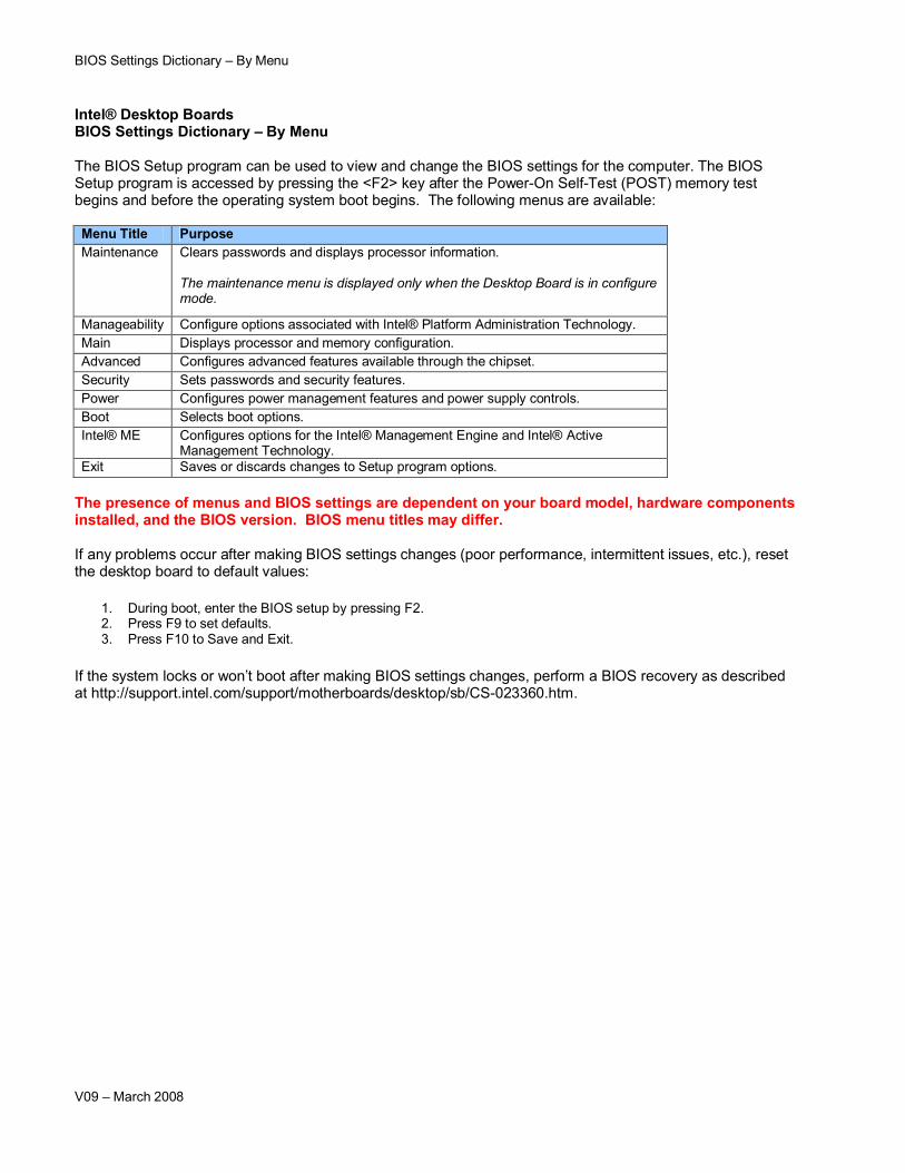
BIOS Settings Dictionary – By Menu V09 – March 2008 Intel® Desktop Boards BIOS Settings Dictionary – By Menu The BIOS Setup program can be used to view and change the BIOS settings for the computer. The BIOS Setup program is accessed by pressing the <F2> key after the Power-On Self-Test (POST) memory test begins and before the operating system boot begins. The following menus are available: Menu Title Purpose Maintenance Clears passwords and displays processor information. The maintenance menu is displayed only when the Desktop Board is in configure mode. Manageability Configure options associated with Intel® Platform Administration Technology. Main Displays processor and memory configuration. Advanced Configures advanced features available through the chipset. Security Sets passwords and security features. Power Configures power management features and power supply controls. Boot Selects boot options. Intel® ME Configures options for the Intel® Management Engine and Intel® Active Management Technology. Exit Saves or discards changes to Setup program options. The presence of menus and BIOS settings are dependent on your board model, hardware components installed, and the BIOS version. BIOS menu titles may differ. If any problems occur after making BIOS settings changes (poor performance, intermittent issues, etc.), reset the desktop board to default values: 1. During boot, enter the BIOS setup by pressing F2. 2. Press F9 to set defaults. 3. Press F10 to Save and Exit. If the system locks or won’t boot after making BIOS settings changes, perform a BIOS recovery as described at http://support.intel.com/support/motherboards/desktop/sb/CS-023360.htm.
Transcript
BIOS Settings Dictionary – By Menu
V09 – March 2008
Intel® Desktop BoardsBIOS Settings Dictionary – By Menu
The BIOS Setup program can be used to view and change the BIOS settings for the computer. The BIOS Setup program is accessed by pressing the <F2> key after the Power-On Self-Test (POST) memory test begins and before the operating system boot begins. The following menus are available:
Menu Title PurposeMaintenance Clears passwords and displays processor information.
The maintenance menu is displayed only when the Desktop Board is in configure mode.
Manageability Configure options associated with Intel® Platform Administration Technology.Main Displays processor and memory configuration.Advanced Configures advanced features available through the chipset.Security Sets passwords and security features.Power Configures power management features and power supply controls.Boot Selects boot options.Intel® ME Configures options for the Intel® Management Engine and Intel® Active
Management Technology.Exit Saves or discards changes to Setup program options.
The presence of menus and BIOS settings are dependent on your board model, hardware components installed, and the BIOS version. BIOS menu titles may differ.
If any problems occur after making BIOS settings changes (poor performance, intermittent issues, etc.), reset the desktop board to default values:
1. During boot, enter the BIOS setup by pressing F2.2. Press F9 to set defaults.3. Press F10 to Save and Exit.
If the system locks or won’t boot after making BIOS settings changes, perform a BIOS recovery as described at http://support.intel.com/support/motherboards/desktop/sb/CS-023360.htm.
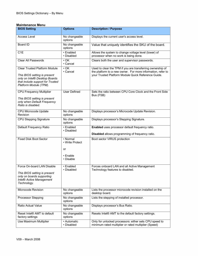
Value that uniquely identifies the SKU of the board.
C1E • Enabled • Disabled
Allows the system to change voltage level (lower) of processor when no work is being done.
Clear All Passwords • OK• Cancel
Clears both the user and supervisor passwords.
Clear Trusted Platform Module
This BIOS setting is present only on Intel® Desktop Boards that include support for Trusted Platform Module (TPM).
• OK• Cancel
Used to clear the TPM if you are transferring ownership of the platform to a new owner. For more information, refer to your Trusted Platform Module Quick Reference Guide.
CPU Frequency Multiplier
This BIOS setting is present only when Default Frequency Ratio is disabled.
User Defined Sets the ratio between CPU Core Clock and the Front Side Bus (FSB)
CPU Microcode Update Revision
No changeable options
Displays processor’s Microcode Update Revision.
CPU Stepping Signature No changeable options
Displays processor’s Stepping Signature.
Default Frequency Ratio • Enabled • Disabled
Enabled uses processor default frequency ratio.
Disabled allows programming of frequency ratio.
Fixed Disk Boot Sector • Normal• Write Protect
or
• Enable• Disable
Boot sector VIRUS protection
Force On-board LAN Disable
This BIOS setting is present only on boards supporting Intel® Active Management Technology.
• Enabled • Disabled
Forces onboard LAN and all Active Management Technology features to disabled.
Microcode Revision No changeable options
Lists the processor microcode revision installed on thedesktop board.
Processor Stepping No changeable options
Lists the stepping of installed processor.
Ratio Actual Value No changeable options
Displays processor’s Bus Ratio.
Reset Intel® AMT to default factory settings
No changeable options
Resets Intel® AMT to the default factory settings.
Use Maximum Multiplier • Automatic • Disabled
Only for unlocked processors: either sets CPU speed to minimum rated multiplier or rated multiplier (Speed)
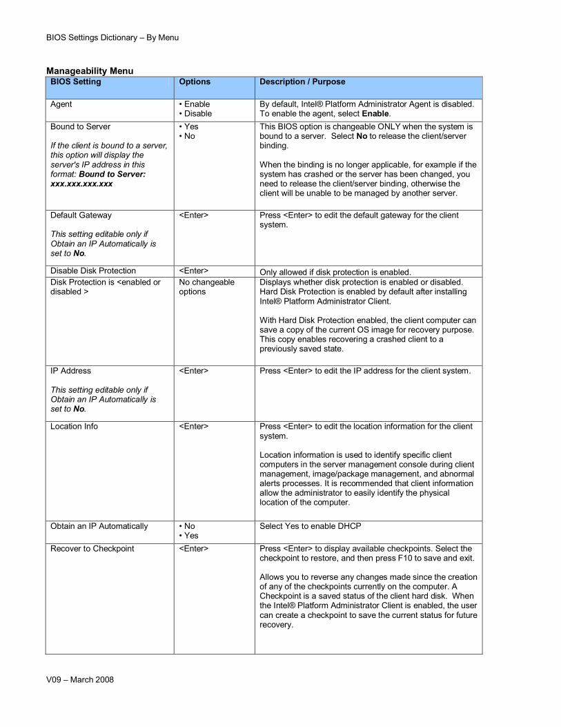
By default, Intel® Platform Administrator Agent is disabled. To enable the agent, select Enable.
Bound to Server
If the client is bound to a server, this option will display the server's IP address in this format: Bound to Server: xxx.xxx.xxx.xxx
• Yes• No
This BIOS option is changeable ONLY when the system is bound to a server. Select No to release the client/server binding.
When the binding is no longer applicable, for example if the system has crashed or the server has been changed, you need to release the client/server binding, otherwise the client will be unable to be managed by another server.
Default Gateway
This setting editable only if Obtain an IP Automatically is set to No.
<Enter> Press <Enter> to edit the default gateway for the client system.
Disable Disk Protection <Enter> Only allowed if disk protection is enabled.Disk Protection is <enabled or disabled >
No changeable options
Displays whether disk protection is enabled or disabled. Hard Disk Protection is enabled by default after installing Intel® Platform Administrator Client.
With Hard Disk Protection enabled, the client computer can save a copy of the current OS image for recovery purpose. This copy enables recovering a crashed client to a previously saved state.
IP Address
This setting editable only if Obtain an IP Automatically is set to No.
<Enter> Press <Enter> to edit the IP address for the client system.
Location Info <Enter> Press <Enter> to edit the location information for the client system.
Location information is used to identify specific client computers in the server management console during client management, image/package management, and abnormal alerts processes. It is recommended that client information allow the administrator to easily identify the physical location of the computer.
Obtain an IP Automatically • No• Yes
Select Yes to enable DHCP
Recover to Checkpoint <Enter> Press <Enter> to display available checkpoints. Select the checkpoint to restore, and then press F10 to save and exit.
Allows you to reverse any changes made since the creation of any of the checkpoints currently on the computer. A Checkpoint is a saved status of the client hard disk. When the Intel® Platform Administrator Client is enabled, the user can create a checkpoint to save the current status for future recovery.
BIOS Settings Dictionary – By Menu
V09 – March 2008
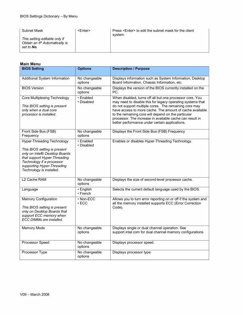
Subnet Mask
This setting editable only if Obtain an IP Automatically is set to No.
<Enter> Press <Enter> to edit the subnet mask for the client system.
Main MenuBIOS Setting Options Description / Purpose
Additional System Information No changeable options
Displays information such as System Information, Desktop Board Information, Chassis Information, etc.
BIOS Version No changeable options
Displays the version of the BIOS currently installed on the PC.
Core Multiplexing Technology
This BIOS setting is present only when a dual core processor is installed.
• Enabled • Disabled
When disabled, turns off all but one processor core. You may need to disable this for legacy operating systems that do not support multiple cores. The remaining core may have access to more cache. The amount of cache available to the remaining core will depend on the particular processor. The increase in available cache can result in better performance under certain applications.
Front Side Bus (FSB) Frequency
No changeable options
Displays the Front Side Bus (FSB) Frequency
Hyper-Threading Technology
This BIOS setting is present only on Intel® Desktop Boards that support Hyper-Threading Technology if a processor supporting Hyper-Threading Technology is installed.
• Enabled • Disabled
Enables or disables Hyper-Threading Technology.
L2 Cache RAM No changeable options
Displays the size of second-level processor cache.
Language • English • French
Selects the current default language used by the BIOS.
Memory Configuration
This BIOS setting is present only on Desktop Boards that support ECC memory when ECC DIMMs are installed.
• Non-ECC • ECC
Allows you to turn error reporting on or off if the system and all the memory installed supports ECC (Error Correction Code).
Memory Mode No changeable options
Displays single or dual channel operation. See support.intel.com for dual channel memory configurations
Processor Speed No changeable options
Displays processor speed.
Processor Type No changeable options
Displays processor type.
BIOS Settings Dictionary – By Menu
V09 – March 2008
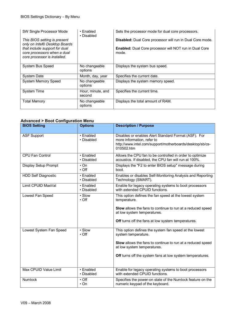
SW Single Processor Mode
This BIOS setting is present only on Intel® Desktop Boards that include support for dual core processors when a dual core processor is installed.
• Enabled • Disabled
Sets the processor mode for dual core processors.
Disabled: Dual Core processor will run in Dual Core mode.
Enabled: Dual Core processor will NOT run in Dual Core mode.
System Bus Speed No changeable options
Displays the system bus speed.
System Date Month, day, year Specifies the current date.System Memory Speed No changeable
Warning: This setting is intended for validation and test purposes only. Altering clock frequencies may reduce system stability and/or the useful life of the system and processor. Operation at settings beyond component specification is not covered by Intel component warranties. If any problems occur during operation at non-default settings, reset the board to default values.
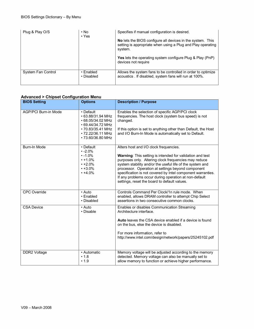
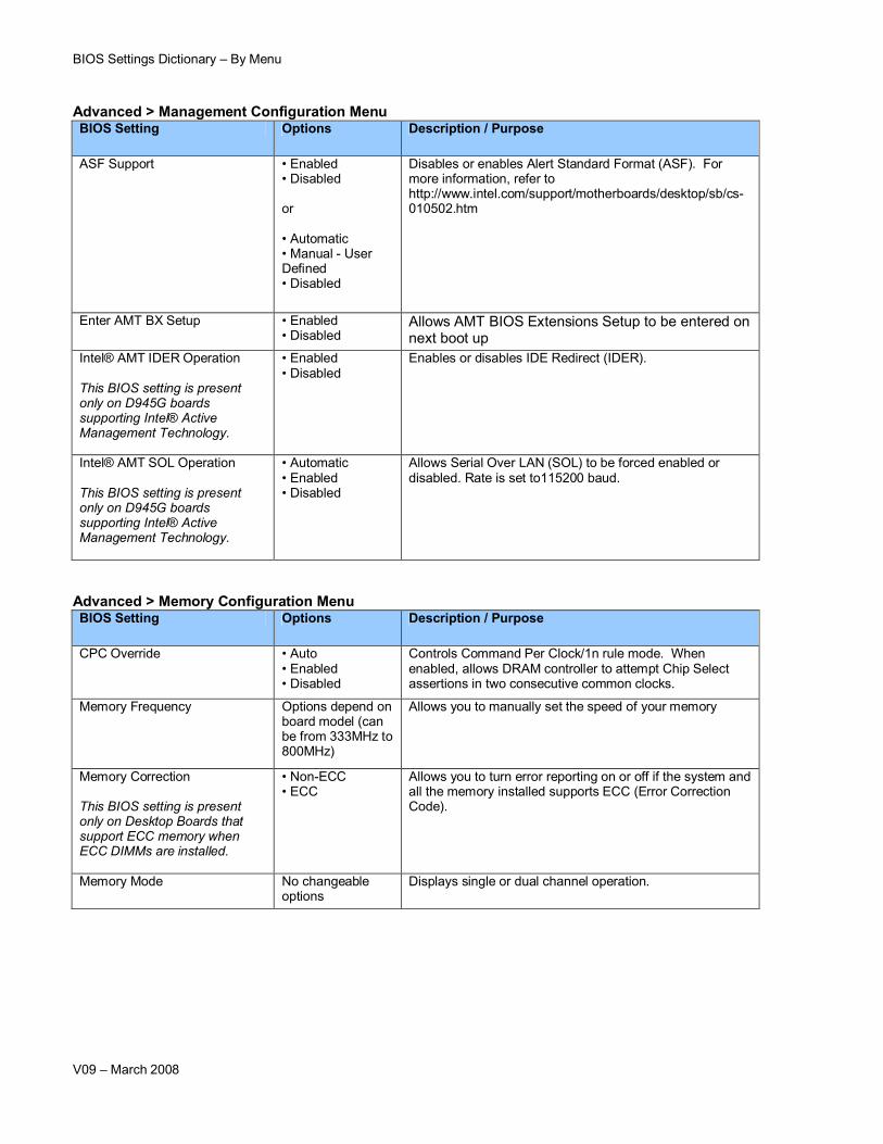
CPC Override • Auto • Enabled• Disabled
Controls Command Per Clock/1n rule mode. When enabled, allows DRAM controller to attempt Chip Select assertions in two consecutive common clocks.
CSA Device • Auto • Disable
Enables or disables Communication Streaming Architecture interface.
Auto leaves the CSA device enabled if a device is found on the bus, else the device is disabled.
For more information, refer tohttp://www.intel.com/design/network/papers/25245102.pdf
DDR2 Voltage • Automatic• 1.8• 1.9
Memory voltage will be adjusted according to the memory detected. Memory voltage can also be manually set to allow memory to function or achieve higher performance.
BIOS Settings Dictionary – By Menu
V09 – March 2008
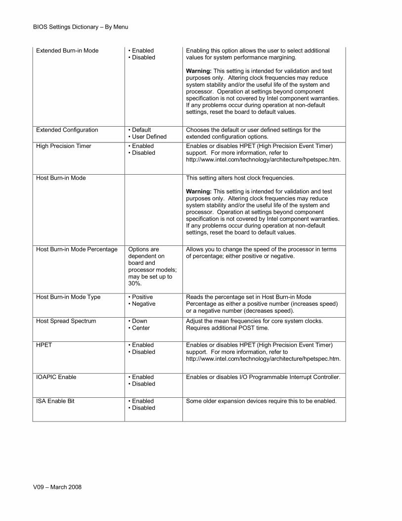
Extended Burn-in Mode • Enabled • Disabled
Enabling this option allows the user to select additional values for system performance margining.
Warning: This setting is intended for validation and test purposes only. Altering clock frequencies may reduce system stability and/or the useful life of the system and processor. Operation at settings beyond component specification is not covered by Intel component warranties. If any problems occur during operation at non-default settings, reset the board to default values.
Extended Configuration • Default • User Defined
Chooses the default or user defined settings for the extended configuration options.
High Precision Timer • Enabled • Disabled
Enables or disables HPET (High Precision Event Timer) support. For more information, refer to http://www.intel.com/technology/architecture/hpetspec.htm.
Host Burn-in Mode This setting alters host clock frequencies.
Warning: This setting is intended for validation and test purposes only. Altering clock frequencies may reduce system stability and/or the useful life of the system and processor. Operation at settings beyond component specification is not covered by Intel component warranties. If any problems occur during operation at non-default settings, reset the board to default values.
Host Burn-in Mode Percentage Options are dependent on board and processor models; may be set up to 30%.
Allows you to change the speed of the processor in terms of percentage; either positive or negative.
Host Burn-in Mode Type • Positive• Negative
Reads the percentage set in Host Burn-in Mode Percentage as either a positive number (increases speed) or a negative number (decreases speed).
Host Spread Spectrum • Down • Center
Adjust the mean frequencies for core system clocks. Requires additional POST time.
HPET • Enabled • Disabled
Enables or disables HPET (High Precision Event Timer) support. For more information, refer to http://www.intel.com/technology/architecture/hpetspec.htm.
IOAPIC Enable • Enabled • Disabled
Enables or disables I/O Programmable Interrupt Controller.
ISA Enable Bit • Enabled • Disabled
Some older expansion devices require this to be enabled.
BIOS Settings Dictionary – By Menu
V09 – March 2008
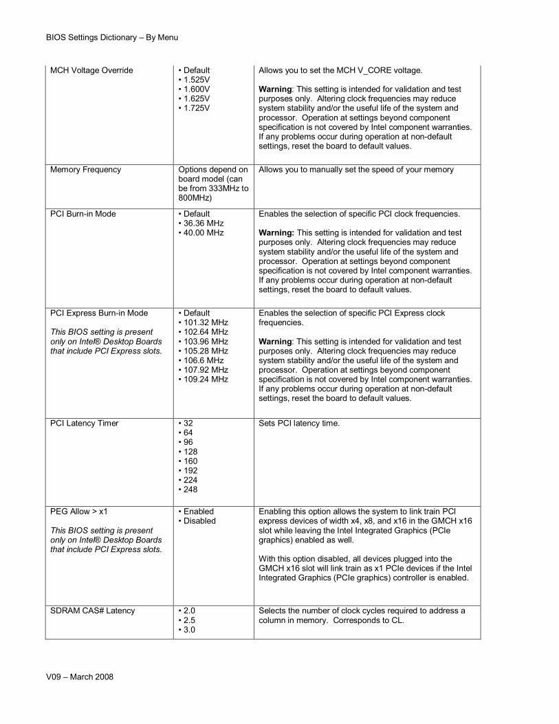
MCH Voltage Override • Default• 1.525V• 1.600V• 1.625V• 1.725V
Allows you to set the MCH V_CORE voltage.
Warning: This setting is intended for validation and test purposes only. Altering clock frequencies may reduce system stability and/or the useful life of the system and processor. Operation at settings beyond component specification is not covered by Intel component warranties. If any problems occur during operation at non-default settings, reset the board to default values.
Memory Frequency Options depend on board model (can be from 333MHz to 800MHz)
Allows you to manually set the speed of your memory
PCI Burn-in Mode • Default • 36.36 MHz• 40.00 MHz
Enables the selection of specific PCI clock frequencies.
Warning: This setting is intended for validation and test purposes only. Altering clock frequencies may reduce system stability and/or the useful life of the system and processor. Operation at settings beyond component specification is not covered by Intel component warranties. If any problems occur during operation at non-default settings, reset the board to default values.
PCI Express Burn-in Mode
This BIOS setting is present only on Intel® Desktop Boards that include PCI Express slots.
Enables the selection of specific PCI Express clock frequencies.
Warning: This setting is intended for validation and test purposes only. Altering clock frequencies may reduce system stability and/or the useful life of the system and processor. Operation at settings beyond component specification is not covered by Intel component warranties. If any problems occur during operation at non-default settings, reset the board to default values.
This BIOS setting is present only on Intel® Desktop Boards that include PCI Express slots.
• Enabled • Disabled
Enabling this option allows the system to link train PCI express devices of width x4, x8, and x16 in the GMCH x16 slot while leaving the Intel Integrated Graphics (PCIe graphics) enabled as well.
With this option disabled, all devices plugged into the GMCH x16 slot will link train as x1 PCIe devices if the Intel Integrated Graphics (PCIe graphics) controller is enabled.
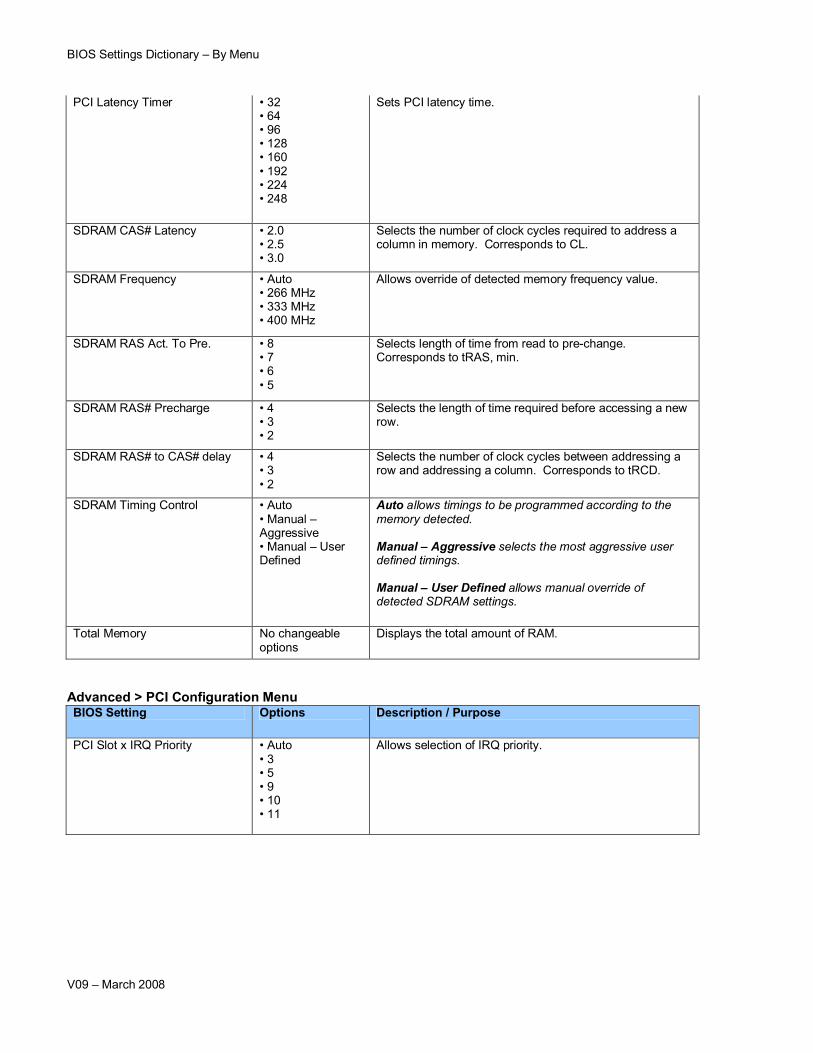
SDRAM CAS# Latency • 2.0• 2.5• 3.0
Selects the number of clock cycles required to address a column in memory. Corresponds to CL.
BIOS Settings Dictionary – By Menu
V09 – March 2008
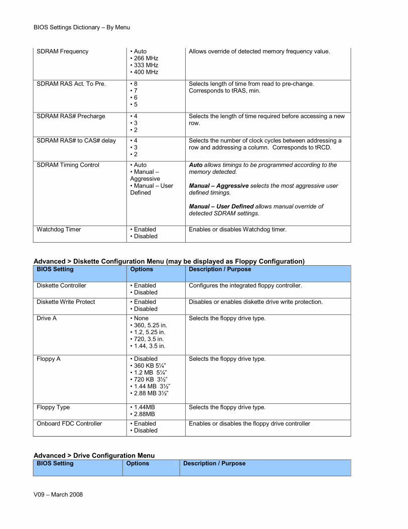
SDRAM Frequency • Auto • 266 MHz• 333 MHz• 400 MHz
Allows override of detected memory frequency value.
SDRAM RAS Act. To Pre. • 8 • 7• 6• 5
Selects length of time from read to pre-change. Corresponds to tRAS, min.
SDRAM RAS# Precharge • 4• 3 • 2
Selects the length of time required before accessing a new row.
SDRAM RAS# to CAS# delay • 4• 3 • 2
Selects the number of clock cycles between addressing a row and addressing a column. Corresponds to tRCD.
SDRAM Timing Control • Auto • Manual –Aggressive• Manual – User Defined
Auto allows timings to be programmed according to the memory detected.
Manual – Aggressive selects the most aggressive user defined timings.
Manual – User Defined allows manual override of detected SDRAM settings.
Watchdog Timer • Enabled • Disabled
Enables or disables Watchdog timer.
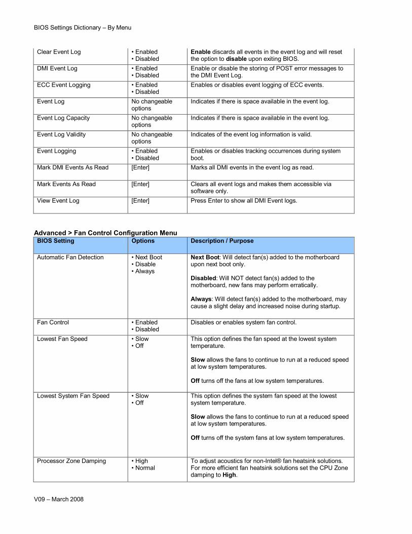
Advanced > Diskette Configuration Menu (may be displayed as Floppy Configuration)BIOS Setting Options Description / Purpose
Diskette Controller • Enabled • Disabled
Configures the integrated floppy controller.
Diskette Write Protect • Enabled • Disabled
Disables or enables diskette drive write protection.
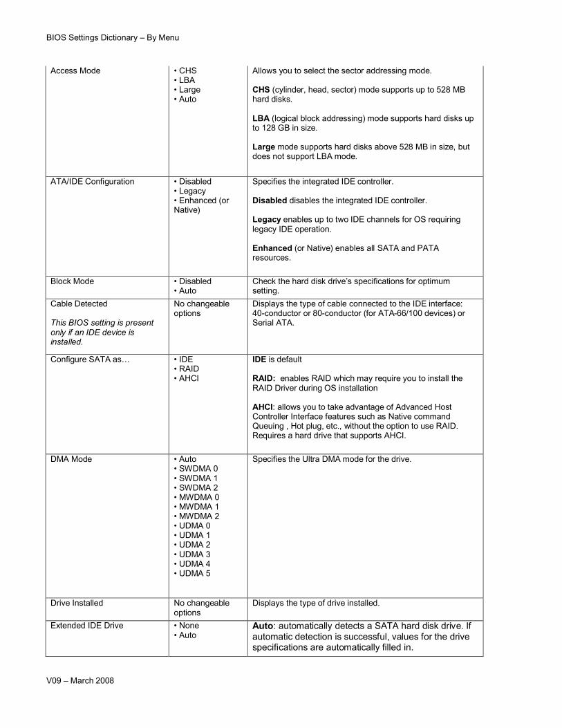
Drive A • None• 360, 5.25 in.• 1.2, 5.25 in.• 720, 3.5 in. • 1.44, 3.5 in.
Legacy enables up to two IDE channels for OS requiring legacy IDE operation.
Enhanced (or Native) enables all SATA and PATA resources.
Block Mode • Disabled• Auto
Check the hard disk drive’s specifications for optimum setting.
Cable Detected
This BIOS setting is present only if an IDE device is installed.
No changeable options
Displays the type of cable connected to the IDE interface: 40-conductor or 80-conductor (for ATA-66/100 devices) or Serial ATA.
Configure SATA as… • IDE• RAID• AHCI
IDE is default
RAID: enables RAID which may require you to install the RAID Driver during OS installation
AHCI: allows you to take advantage of Advanced Host Controller Interface features such as Native command Queuing , Hot plug, etc., without the option to use RAID.Requires a hard drive that supports AHCI.
Auto: automatically detects a SATA hard disk drive. If automatic detection is successful, values for the drive specifications are automatically filled in.
BIOS Settings Dictionary – By Menu
V09 – March 2008
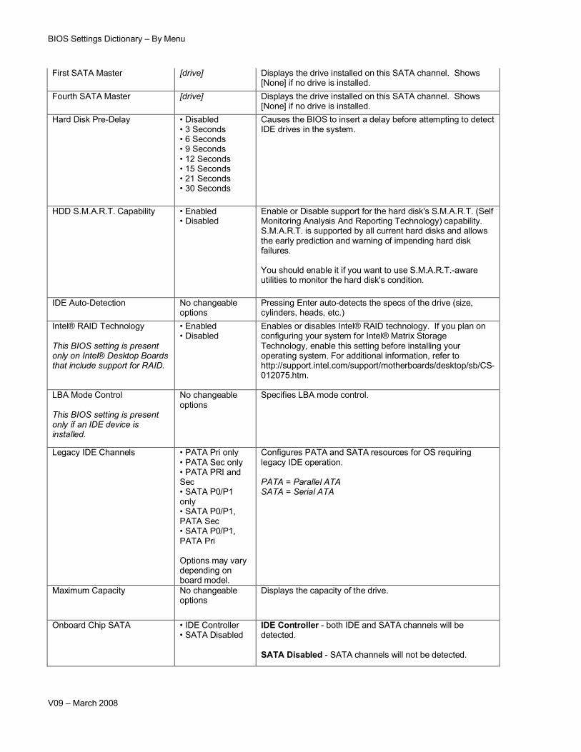
First SATA Master [drive] Displays the drive installed on this SATA channel. Shows [None] if no drive is installed.
Fourth SATA Master [drive] Displays the drive installed on this SATA channel. Shows [None] if no drive is installed.
Hard Disk Pre-Delay • Disabled • 3 Seconds• 6 Seconds• 9 Seconds• 12 Seconds• 15 Seconds• 21 Seconds• 30 Seconds
Causes the BIOS to insert a delay before attempting to detect IDE drives in the system.
HDD S.M.A.R.T. Capability • Enabled • Disabled
Enable or Disable support for the hard disk's S.M.A.R.T. (Self Monitoring Analysis And Reporting Technology) capability. S.M.A.R.T. is supported by all current hard disks and allows the early prediction and warning of impending hard disk failures.
You should enable it if you want to use S.M.A.R.T.-aware utilities to monitor the hard disk's condition.
IDE Auto-Detection No changeable options
Pressing Enter auto-detects the specs of the drive (size, cylinders, heads, etc.)
Intel® RAID Technology
This BIOS setting is present only on Intel® Desktop Boards that include support for RAID.
• Enabled • Disabled
Enables or disables Intel® RAID technology. If you plan on configuring your system for Intel® Matrix Storage Technology, enable this setting before installing your operating system. For additional information, refer to http://support.intel.com/support/motherboards/desktop/sb/CS-012075.htm.
LBA Mode Control
This BIOS setting is present only if an IDE device is installed.
No changeable options
Specifies LBA mode control.
Legacy IDE Channels • PATA Pri only• PATA Sec only• PATA PRI and Sec • SATA P0/P1 only • SATA P0/P1, PATA Sec• SATA P0/P1, PATA Pri
Options may vary depending on board model.
Configures PATA and SATA resources for OS requiring legacy IDE operation.
PATA = Parallel ATASATA = Serial ATA
Maximum Capacity No changeable options
Displays the capacity of the drive.
Onboard Chip SATA • IDE Controller• SATA Disabled
IDE Controller - both IDE and SATA channels will be detected.
SATA Disabled - SATA channels will not be detected.
BIOS Settings Dictionary – By Menu
V09 – March 2008
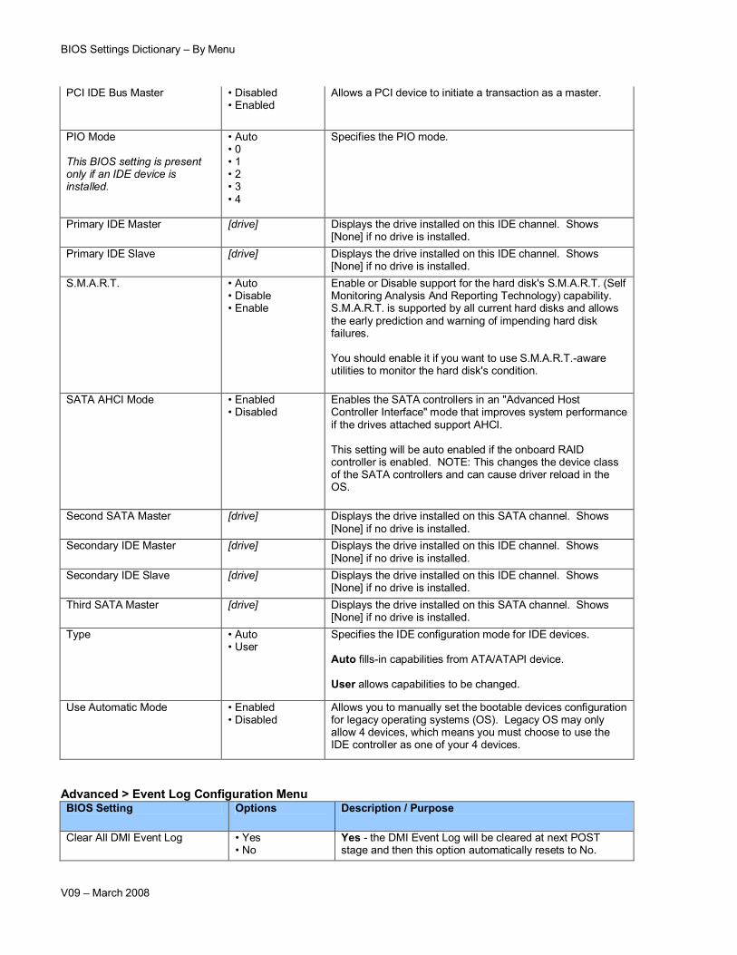
PCI IDE Bus Master • Disabled• Enabled
Allows a PCI device to initiate a transaction as a master.
PIO Mode
This BIOS setting is present only if an IDE device is installed.
• Auto • 0• 1• 2• 3• 4
Specifies the PIO mode.
Primary IDE Master [drive] Displays the drive installed on this IDE channel. Shows [None] if no drive is installed.
Primary IDE Slave [drive] Displays the drive installed on this IDE channel. Shows [None] if no drive is installed.
S.M.A.R.T. • Auto • Disable• Enable
Enable or Disable support for the hard disk's S.M.A.R.T. (Self Monitoring Analysis And Reporting Technology) capability. S.M.A.R.T. is supported by all current hard disks and allows the early prediction and warning of impending hard disk failures.
You should enable it if you want to use S.M.A.R.T.-aware utilities to monitor the hard disk's condition.
SATA AHCI Mode • Enabled • Disabled
Enables the SATA controllers in an "Advanced Host Controller Interface" mode that improves system performance if the drives attached support AHCI.
This setting will be auto enabled if the onboard RAID controller is enabled. NOTE: This changes the device class of the SATA controllers and can cause driver reload in the OS.
Second SATA Master [drive] Displays the drive installed on this SATA channel. Shows [None] if no drive is installed.
Secondary IDE Master [drive] Displays the drive installed on this IDE channel. Shows [None] if no drive is installed.
Secondary IDE Slave [drive] Displays the drive installed on this IDE channel. Shows [None] if no drive is installed.
Third SATA Master [drive] Displays the drive installed on this SATA channel. Shows [None] if no drive is installed.
Type • Auto • User
Specifies the IDE configuration mode for IDE devices.
Auto fills-in capabilities from ATA/ATAPI device.
User allows capabilities to be changed.
Use Automatic Mode • Enabled • Disabled
Allows you to manually set the bootable devices configuration for legacy operating systems (OS). Legacy OS may only allow 4 devices, which means you must choose to use the IDE controller as one of your 4 devices.
This BIOS setting is present only on certain BTX form factor Intel® Desktop Boards.
No changeable options
Displays the temperature near the remote thermal diode on BTX form factor boards.
Aux Fan Speed No changeable options
Displays aux fan speed.
Chassis Fan Speed No changeable options
Displays chassis fan speed
Chassis Inlet Fan No changeable options
Displays front chassis fan speed
Chassis Outlet Fan No changeable options
Displays rear chassis fan speed
CPU Cooling Fan No changeable options
Displays fan speed of the CPU fan
CPU Die/Package Temperature No changeable options
Displays processor's temperature.
CPU Fan Speed No changeable options
Displays processor fan speed
CPU Temperature No changeable options
Displays processor's temperature.
CPU Thermal Module Fan No changeable options
Displays fan speed of the CPU fan
Front Fan Speed No changeable options
Displays front fan speed.
BIOS Settings Dictionary – By Menu
V09 – March 2008
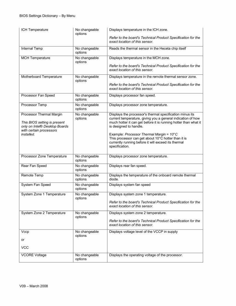
ICH Temperature No changeable options
Displays temperature in the ICH zone.
Refer to the board's Technical Product Specification for the exact location of this sensor.
Internal Temp No changeable options
Reads the thermal sensor in the Heceta chip itself
MCH Temperature No changeable options
Displays temperature in the MCH zone.
Refer to the board's Technical Product Specification for the exact location of this sensor.
Motherboard Temperature No changeable options
Displays temperature in the remote thermal sensor zone.
Refer to the board's Technical Product Specification for the exact location of this sensor.
Processor Fan Speed No changeable options
Displays processor fan speed.
Processor Temp No changeable options
Displays processor zone temperature.
Processor Thermal Margin
This BIOS setting is present only on Intel® Desktop Boards with certain processors installed.
No changeable options
Displays the processor's thermal specification minus its current temperature, giving you a general indication of how much hotter it can get before it is running hotter than what it is designed to handle.
Example: Processor Thermal Margin = 10°C This processor can get about 10°C hotter than it is currently running before it will exceed its thermal specification.
Processor Zone Temperature No changeable options
Displays processor zone temperature.
Rear Fan Speed No changeable options
Displays rear fan speed.
Remote Temp No changeable options
Displays the temperature of the onboard remote thermal diode.
System Fan Speed No changeable options
Displays system fan speed
System Zone 1 Temperature No changeable options
Displays system zone 1 temperature.
Refer to the board's Technical Product Specification for the exact location of this sensor.
System Zone 2 Temperature No changeable options
Displays system zone 2 temperature.
Refer to the board's Technical Product Specification for the exact location of this sensor.
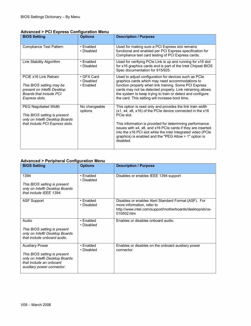
Used for making sure a PCI Express slot remains functional and enabled per PCI Express specification for Compliance test card testing of PCI Express cards.
Link Stability Algorithm • Enabled • Disabled
Used for verifying PCIe Link is up and running for x16 slot for x16 graphics cards and is part of the Intel Chipset BIOS Spec documentation for 915/925.
PCIE x16 Link Retrain
This BIOS setting may be present on Intel® Desktop Boards that include PCI Express slots.
• GFX Card• Disabled • Enabled
Used to adjust configuration for devices such as PCIe graphics cards which may need accommodations to function properly when link training. Some PCI Express cards may not be detected properly. Link retraining allows the system to keep trying to train or detect and configure the card. This setting will increase boot time.
PEG Negotiated Width
This BIOS setting is present only on Intel® Desktop Boards that include PCI Express slots.
No changeable options
This option is read only and provides the link train width (x1, x4, x8, x16) of the PCIe device connected in the x16 PCIe slot.
This information is provided for determining performance issues with x4, x8, and x16 PCIe cards if they are inserted into the x16 PCI slot while the Intel Integrated video (PCIe graphics) is enabled and the "PEG Allow > 1" option is disabled.
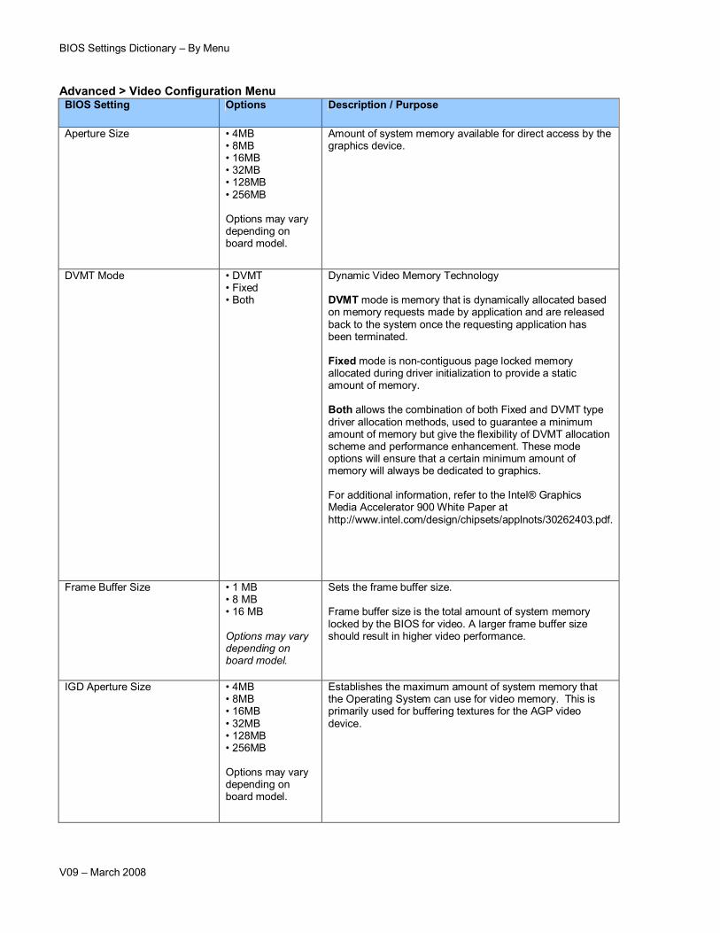
Amount of system memory available for direct access by the graphics device.
DVMT Mode • DVMT • Fixed• Both
Dynamic Video Memory Technology
DVMT mode is memory that is dynamically allocated based on memory requests made by application and are released back to the system once the requesting application has been terminated.
Fixed mode is non-contiguous page locked memory allocated during driver initialization to provide a static amount of memory.
Both allows the combination of both Fixed and DVMT type driver allocation methods, used to guarantee a minimum amount of memory but give the flexibility of DVMT allocation scheme and performance enhancement. These mode options will ensure that a certain minimum amount of memory will always be dedicated to graphics.
For additional information, refer to the Intel® Graphics Media Accelerator 900 White Paper at http://www.intel.com/design/chipsets/applnots/30262403.pdf.
Frame Buffer Size • 1 MB• 8 MB• 16 MB
Options may vary depending on board model.
Sets the frame buffer size.
Frame buffer size is the total amount of system memory locked by the BIOS for video. A larger frame buffer size should result in higher video performance.
Establishes the maximum amount of system memory that the Operating System can use for video memory. This is primarily used for buffering textures for the AGP video device.
BIOS Settings Dictionary – By Menu
V09 – March 2008
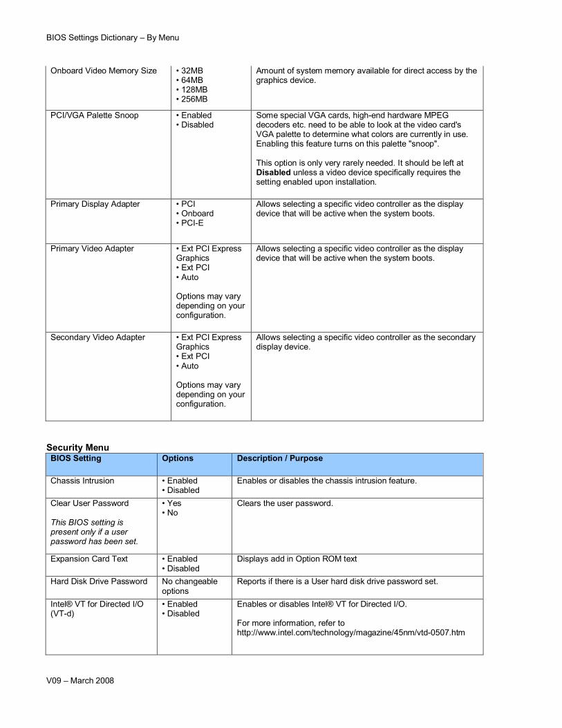
Onboard Video Memory Size • 32MB • 64MB• 128MB• 256MB
Amount of system memory available for direct access by the graphics device.
PCI/VGA Palette Snoop • Enabled • Disabled
Some special VGA cards, high-end hardware MPEG decoders etc. need to be able to look at the video card's VGA palette to determine what colors are currently in use. Enabling this feature turns on this palette "snoop".
This option is only very rarely needed. It should be left at Disabled unless a video device specifically requires the setting enabled upon installation.
Primary Display Adapter • PCI• Onboard• PCI-E
Allows selecting a specific video controller as the display device that will be active when the system boots.
Primary Video Adapter • Ext PCI Express Graphics• Ext PCI• Auto
Options may vary depending on your configuration.
Allows selecting a specific video controller as the display device that will be active when the system boots.
Secondary Video Adapter • Ext PCI Express Graphics• Ext PCI• Auto
Options may vary depending on your configuration.
Allows selecting a specific video controller as the secondary display device.
Enables or disables the chassis intrusion feature.
Clear User Password
This BIOS setting is present only if a user password has been set.
• Yes • No
Clears the user password.
Expansion Card Text • Enabled • Disabled
Displays add in Option ROM text
Hard Disk Drive Password No changeable options
Reports if there is a User hard disk drive password set.
Intel® VT for Directed I/O (VT-d)
• Enabled • Disabled
Enables or disables Intel® VT for Directed I/O.
For more information, refer to http://www.intel.com/technology/magazine/45nm/vtd-0507.htm
BIOS Settings Dictionary – By Menu
V09 – March 2008
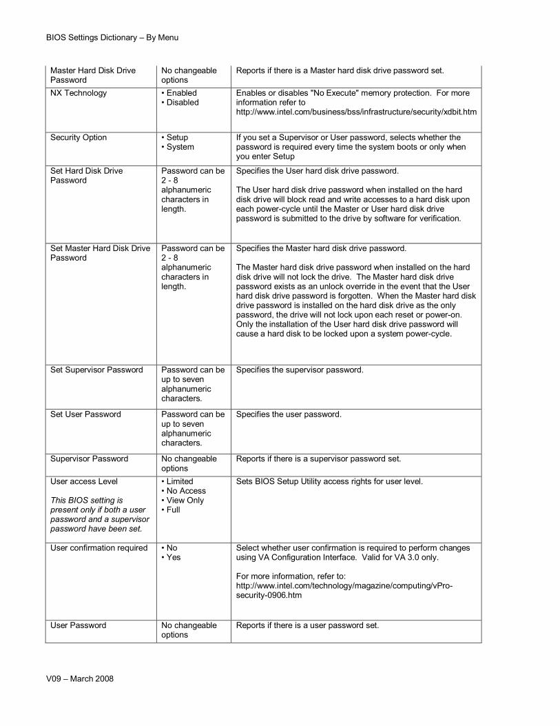
Master Hard Disk Drive Password
No changeable options
Reports if there is a Master hard disk drive password set.
NX Technology • Enabled • Disabled
Enables or disables "No Execute" memory protection. For more information refer to http://www.intel.com/business/bss/infrastructure/security/xdbit.htm
Security Option • Setup• System
If you set a Supervisor or User password, selects whether the password is required every time the system boots or only when you enter Setup
Set Hard Disk Drive Password
Password can be 2 - 8 alphanumeric characters in length.
Specifies the User hard disk drive password.
The User hard disk drive password when installed on the hard disk drive will block read and write accesses to a hard disk upon each power-cycle until the Master or User hard disk drive password is submitted to the drive by software for verification.
Set Master Hard Disk Drive Password
Password can be 2 - 8 alphanumeric characters in length.
Specifies the Master hard disk drive password.
The Master hard disk drive password when installed on the hard disk drive will not lock the drive. The Master hard disk drive password exists as an unlock override in the event that the User hard disk drive password is forgotten. When the Master hard disk drive password is installed on the hard disk drive as the only password, the drive will not lock upon each reset or power-on. Only the installation of the User hard disk drive password will cause a hard disk to be locked upon a system power-cycle.
Set Supervisor Password Password can be up to seven alphanumeric characters.
Specifies the supervisor password.
Set User Password Password can be up to seven alphanumeric characters.
Specifies the user password.
Supervisor Password No changeable options
Reports if there is a supervisor password set.
User access Level
This BIOS setting is present only if both a user password and a supervisor password have been set.
• Limited• No Access• View Only• Full
Sets BIOS Setup Utility access rights for user level.
User confirmation required • No• Yes
Select whether user confirmation is required to perform changes using VA Configuration Interface. Valid for VA 3.0 only.
For more information, refer to: http://www.intel.com/technology/magazine/computing/vPro-security-0906.htm
User Password No changeable options
Reports if there is a user password set.
BIOS Settings Dictionary – By Menu
V09 – March 2008
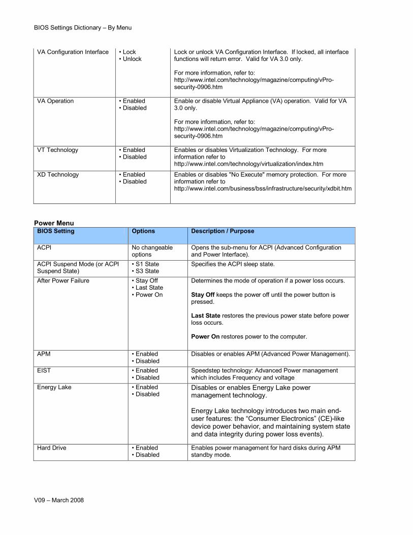
VA Configuration Interface • Lock• Unlock
Lock or unlock VA Configuration Interface. If locked, all interface functions will return error. Valid for VA 3.0 only.
For more information, refer to: http://www.intel.com/technology/magazine/computing/vPro-security-0906.htm
VA Operation • Enabled • Disabled
Enable or disable Virtual Appliance (VA) operation. Valid for VA 3.0 only.
For more information, refer to: http://www.intel.com/technology/magazine/computing/vPro-security-0906.htm
VT Technology • Enabled • Disabled
Enables or disables Virtualization Technology. For more information refer to http://www.intel.com/technology/virtualization/index.htm
XD Technology • Enabled • Disabled
Enables or disables "No Execute" memory protection. For more information refer to http://www.intel.com/business/bss/infrastructure/security/xdbit.htm
Power MenuBIOS Setting Options Description / Purpose
ACPI No changeable options
Opens the sub-menu for ACPI (Advanced Configuration and Power Interface).
ACPI Suspend Mode (or ACPI Suspend State)
• S1 State• S3 State
Specifies the ACPI sleep state.
After Power Failure • Stay Off• Last State • Power On
Determines the mode of operation if a power loss occurs.
Stay Off keeps the power off until the power button is pressed.
Last State restores the previous power state before power loss occurs.
Power On restores power to the computer.
APM • Enabled • Disabled
Disables or enables APM (Advanced Power Management).
EIST • Enabled • Disabled
Speedstep technology: Advanced Power management which includes Frequency and voltage
Energy Lake • Enabled • Disabled
Disables or enables Energy Lake power management technology.
Energy Lake technology introduces two main end-user features: the “Consumer Electronics” (CE)-like device power behavior, and maintaining system state and data integrity during power loss events).
Hard Drive • Enabled • Disabled
Enables power management for hard disks during APM standby mode.
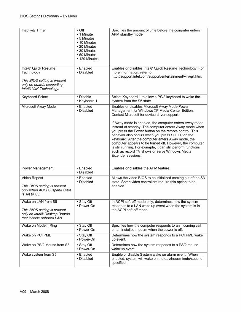
Specifies the amount of time before the computer enters APM standby mode.
Intel® Quick Resume Technology
This BIOS setting is present only on boards supporting Intel® Viiv ̃Technology.
• Enabled • Disabled
Enables or disables Intel® Quick Resume Technology. For more information, refer to http://support.intel.com/support/entertainment/viiv/qrt.htm.
Keyboard Select • Disable• Keyboard 1
Select Keyboard 1 to allow a PS/2 keyboard to wake the system from the S5 state.
Microsoft Away Mode • Enabled • Disabled
Enables or disables Microsoft Away Mode Power Management for Windows XP Media Center Edition. Contact Microsoft for device driver support.
If Away mode is enabled, the computer enters Away mode instead of standby. The computer enters Away mode when you press the Power button on the remote control. This behavior also occurs when you press SLEEP on the keyboard. After the computer enters Away mode, the computer appears to be turned off. However, the computer is still running. For example, it can still perform functions such as record TV shows or serve Windows Media Extender sessions.
Power Management • Enabled • Disabled
Enables or disables the APM feature.
Video Repost
This BIOS setting is present only when ACPI Suspend State is set to S3.
• Enabled • Disabled
Allows the video BIOS to be initialized coming out of the S3 state. Some video controllers require this option to be enabled.
Wake on LAN from S5
This BIOS setting is present only on Intel® Desktop Boards that include onboard LAN.
• Stay Off • Power-On
In ACPI soft-off mode only, determines how the system responds to a LAN wake up event when the system is in the ACPI soft-off mode.
Wake on Modem Ring • Stay Off • Power-On
Specifies how the computer responds to an incoming call on an installed modem when the power is off.
Wake on PCI PME • Stay Off • Power-On
Determines how the system responds to a PCI PME wake up event.
Wake on PS/2 Mouse from S3 • Stay Off • Power-On
Determines how the system responds to a PS/2 mouse wake up event.
Wake system from S5 • Enabled • Disabled
Enable or disable System wake on alarm event. When enabled, system will wake on the day/hour/minute/second specified.
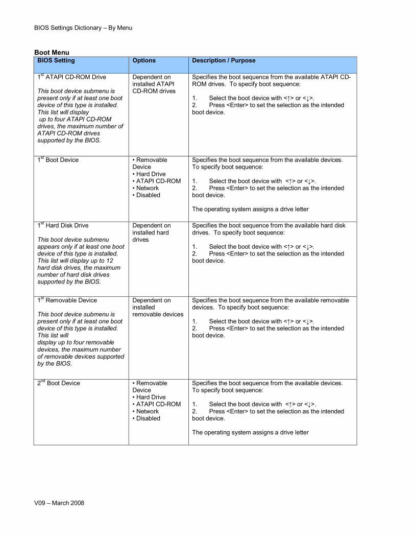
This boot device submenu is present only if at least one boot device of this type is installed. This list will display up to four ATAPI CD-ROM drives, the maximum number of ATAPI CD-ROM drives supported by the BIOS.
Dependent on installed ATAPI CD-ROM drives
Specifies the boot sequence from the available ATAPI CD-ROM drives. To specify boot sequence:
1. Select the boot device with <↑> or <↓>. 2. Press <Enter> to set the selection as the intended boot device.
Specifies the boot sequence from the available devices. To specify boot sequence:
1. Select the boot device with <↑> or <↓>. 2. Press <Enter> to set the selection as the intended boot device.
The operating system assigns a drive letter
1st Hard Disk Drive
This boot device submenu appears only if at least one boot device of this type is installed. This list will display up to 12 hard disk drives, the maximum number of hard disk drives supported by the BIOS.
Dependent on installed hard drives
Specifies the boot sequence from the available hard disk drives. To specify boot sequence:
1. Select the boot device with <↑> or <↓>. 2. Press <Enter> to set the selection as the intended boot device.
1st Removable Device
This boot device submenu is present only if at least one boot device of this type is installed. This list willdisplay up to four removable devices, the maximum number of removable devices supported by the BIOS.
Dependent on installed removable devices
Specifies the boot sequence from the available removable devices. To specify boot sequence:
1. Select the boot device with <↑> or <↓>. 2. Press <Enter> to set the selection as the intended boot device.
Specifies the boot sequence from the available devices. To specify boot sequence:
1. Select the boot device with <↑> or <↓>. 2. Press <Enter> to set the selection as the intended boot device.
The operating system assigns a drive letter
AddOn ROM Display Mode • Enabled • Disabled
Enabled: the logo screen will be followed by the “AddOn ROM” initial screen (the screen showing the add-on card BIOS message).
Disabled: no “Add-On ROM” screen is followed.
ATAPI CD-ROM Drives No changeable options
Opens the ATAPI CD-ROM Drive sub-menu where you may specify the boot sequence from the available ATAPI CD-ROM drives.
Boot Device Priority No changeable options
Opens the Boot Device Priority sub-menu where you may specify the boot sequence from the available types of boot devices.
Boot Drive Order Dependent on installed bootable devices
Allows you to specify the boot sequence from the available types of boot devices.
Boot Menu Type • Normal • Advance
Normal allows you to set boot priority based on type of device.
Advanced allows you to set boot priority for each device regardless of category
Boot to Network • Enabled • Disabled
Disables or enables booting from the network.
Boot to Optical Devices • Enabled • Disabled
Disables or enables booting from optical devices (CD/DVD).
Boot to Removable Devices • Enabled • Disabled
Disables or enables booting from removable devices.
Boot USB Devices First
• Enabled • Disabled Sets USB devices to be first in boot order.
CD/DVD Drive Order Lists all installed CD/DVD devices
Allows you to set the boot order of CD/DVD drives (used when Boot Menu type is set to normal)
CD-ROM Boot Priority Lists all installed CDrom devices
Allows you to set the boot order of CDROM drives
Halt On • All Errors• No Errors• All, But Keyboard
Used to configure what types of POST errors will halt the system boot.
Hard Disk Boot Priority Lists all installed hard drive devices
Allows you to set the boot order of hard drives
BIOS Settings Dictionary – By Menu
V09 – March 2008
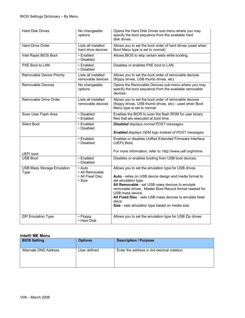
Hard Disk Drives No changeable options
Opens the Hard Disk Drives sub-menu where you may specify the boot sequence from the available hard disk drives.
Hard Drive Order Lists all installed hard drive devices
Allows you to set the boot order of hard drives (used when Boot Menu type is set to normal)
Intel Rapid BIOS Boot • Enabled • Disabled
Allows BIOS to skip certain tests while booting.
PXE Boot to LAN • Enabled • Disabled
Disables or enables PXE boot to LAN.
Removable Device Priority Lists all installed removable devices
Allows you to set the boot order of removable devices (floppy drives, USB thumb drives, etc)
Removable Devices No changeable options
Opens the Removable Devices sub-menu where you may specify the boot sequence from the available removable devices.
Removable Drive Order Lists all installed removable devices
Allows you to set the boot order of removable devices (floppy drives, USB thumb drives, etc) - used when Boot Menu type is set to normal.
Scan User Flash Area • Disabled• Enabled
Enables the BIOS to scan the flash ROM for user binary files that are executed at boot time.
Silent Boot • Enabled • Disabled
Disabled displays normal POST messages.
Enabled displays OEM logo instead of POST messages.
UEFI boot
• Enabled • Disabled
Enables or disables Unified Extended Firmware Interface (UEFI) Boot.
For more information, refer to: http://www.uefi.org/home
USB Boot • Enabled • Disabled
Disables or enables booting from USB boot devices.
USB Mass Storage Emulation Type
• Auto• All Removable• All Fixed Disc• Size
Allows you to set the emulation type for USB drives.
Auto - relies on USB device design and media format to set emulation type.All Removable - set USB mass devices to emulate removable drives. Master Boot Record format needed for USB mass device.All Fixed Disc - sets USB mass devices to emulate fixed discs.Size - sets emulation type based on media size.
ZIP Emulation Type • Floppy • Hard Disk
Allows you to set the emulation type for USB Zip drives
Intel® ME MenuBIOS Setting Options Description / Purpose
Alternate DNS Address User defined Enter the address in dot-decimal notation.
BIOS Settings Dictionary – By Menu
V09 – March 2008
Change Intel® Management Engine Password
User defined Intel® ME password must be changed from the default password prior to gaining access to other ME options. Intel® ME passwords must be between 8 and 32 characters long, have at least one upper case character, one lower case character, one number, and a special character (for example: !, @, #, $, %, ^, &, *).
The system owner should document the new Intel ME password, store it in a secured location (a vault, safe deposit box, or off-site storage), and have it available for future use. This document should be updated after any password change is made.
Compatibility Mode • Intel® AMT Generation 2.0• Intel® AMT Generation 1.0
Depending on the 3rd party management software that is chosen to be used with this system (if any), set the Compatibility Mode appropriate to the management software.
Computer Name User defined Sets the computer name. The computer name must be between 1 and 32 characters long, may contain upper case characters, lower case characters numbers, however spaces, dashes, and any other special characters (for example: !, @, #, $, %, ^, &, *) are not allowed.
DHCP Enabled [X][ ]
Toggle the checkbox (with the Enter key or the Space bar) to enable or disable DHCP.
Domain Name User defined Sets the domain name.
Gateway Address User defined Enter the address in dot-decimal notation.
Idle Time Out User defined A value between 0 and 65535. Sets the number of minutes of idle time before Intel® ME will sleep.
Default value is 0. With this setting, Intel® ME will not sleep, with no power savings.
This option is present only if “Turn on Intel® ME in Sleep States” is enabled.
Intel® ME After Power Failure • Power On• Stay Off
Determines mode of operation if power loss occurs.
Stay Off: Intel® ME will remain off once power is restored.
Power On: Restores ME to the power on state.
IP Address User defined Enter the address in dot-decimal notation.
BIOS Settings Dictionary – By Menu
V09 – March 2008
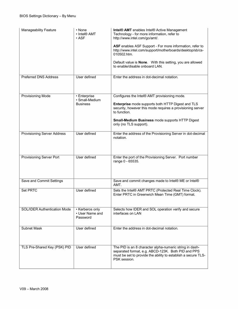
Manageability Feature • None• Intel® AMT• ASF
Intel® AMT enables Intel® Active Management Technology - for more information, refer to http://www.intel.com/go/amt/.
ASF enables ASF Support - For more information, refer to http://www.intel.com/support/motherboards/desktop/sb/cs-010502.htm.
Default value is None. With this setting, you are allowed to enable/disable onboard LAN.
Preferred DNS Address User defined Enter the address in dot-decimal notation.
Provisioning Mode • Enterprise• Small-Medium Business
Configures the Intel® AMT provisioning mode.
Enterprise mode supports both HTTP Digest and TLS security, however this mode requires a provisioning server to function.
Small-Medium Business mode supports HTTP Digest only (no TLS support).
Provisioning Server Address User defined Enter the address of the Provisioning Server in dot-decimal notation.
Provisioning Server Port User defined Enter the port of the Provisioning Server. Port number range 0 - 65535.
Save and Commit Settings Save and commit changes made to Intel® ME or Intel® AMT.
Set PRTC User defined Sets the Intel® AMT PRTC (Protected Real Time Clock). Enter PRTC in Greenwich Mean Time (GMT) format.
SOL/IDER Authentication Mode • Kerberos only• User Name and Password
Selects how IDER and SOL operation verify and secure interfaces on LAN
Subnet Mask User defined Enter the address in dot-decimal notation.
TLS Pre-Shared Key (PSK) PID User defined The PID is an 8 character alpha-numeric string in dash-separated format, e.g. ABCD-123K. Both PID and PPS must be set to provide the ability to establish a secure TLS-PSK session.
BIOS Settings Dictionary – By Menu
V09 – March 2008
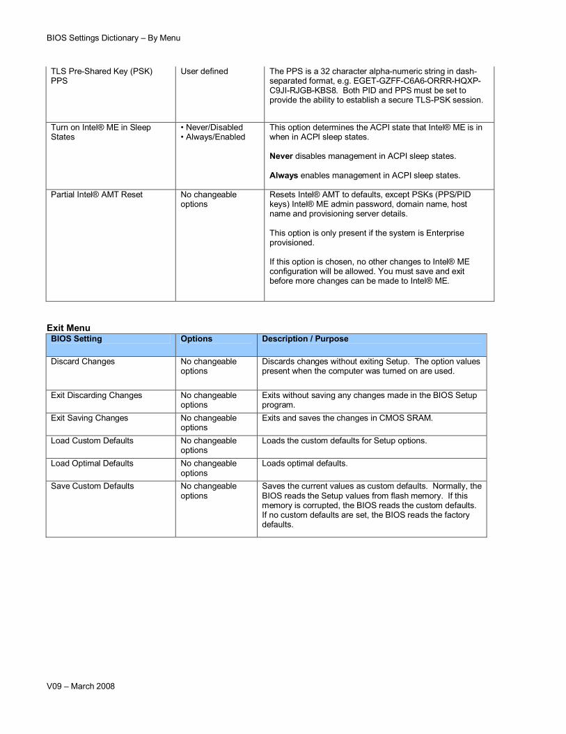
TLS Pre-Shared Key (PSK) PPS
User defined The PPS is a 32 character alpha-numeric string in dash-separated format, e.g. EGET-GZFF-C6A6-ORRR-HQXP-C9JI-RJGB-KBS8. Both PID and PPS must be set to provide the ability to establish a secure TLS-PSK session.
Turn on Intel® ME in Sleep States
• Never/Disabled• Always/Enabled
This option determines the ACPI state that Intel® ME is in when in ACPI sleep states.
Never disables management in ACPI sleep states.
Always enables management in ACPI sleep states.
Partial Intel® AMT Reset No changeable options
Resets Intel® AMT to defaults, except PSKs (PPS/PID keys) Intel® ME admin password, domain name, host name and provisioning server details.
This option is only present if the system is Enterprise provisioned.
If this option is chosen, no other changes to Intel® ME configuration will be allowed. You must save and exit before more changes can be made to Intel® ME.
Discards changes without exiting Setup. The option values present when the computer was turned on are used.
Exit Discarding Changes No changeable options
Exits without saving any changes made in the BIOS Setup program.
Exit Saving Changes No changeable options
Exits and saves the changes in CMOS SRAM.
Load Custom Defaults No changeable options
Loads the custom defaults for Setup options.
Load Optimal Defaults No changeable options
Loads optimal defaults.
Save Custom Defaults No changeable options
Saves the current values as custom defaults. Normally, the BIOS reads the Setup values from flash memory. If this memory is corrupted, the BIOS reads the custom defaults. If no custom defaults are set, the BIOS reads the factory defaults.