16
Intel ® Edison Tutorial: GPIO and I2C Interfaces 1 Intel ® Edison Tutorial: GPIO, Interrupts and I2C Interfaces
| Date post: | 15-Mar-2018 |
| Category: |
Documents |
| Upload: | truongduong |
| View: | 226 times |
| Download: | 0 times |

Intel® Edison Tutorial: GPIO and I2C Interfaces 1
Intel® Edison Tutorial: GPIO, Interrupts and I2C Interfaces

Intel® Edison Tutorial: GPIO and I2C Interfaces 2
Table of Contents
Introduction ..................................................................................................................... 3
List of Required Materials and Equipment ................................................................... 3
Introduction to the mraa Library ................................................................................... 4
GPIO – Blink LED............................................................................................................ 5
Polling and Interrupts .................................................................................................... 8
SIG_INT on Button Press ............................................................................................... 9
Analog Input .................................................................................................................. 12
I2C (Inter-Integrated Circuit) ........................................................................................ 14
Revision history
Version Date Comment
1.0 9/24/2015 Initial release
2.0 1/10/2016 Modified examples

Intel® Edison Tutorial: GPIO and I2C Interfaces 3
Introduction The biggest difference between the Intel Edison and most personal computers is the way these computing devices interface with peripherals. For example, most personal computers have to the following interfaces and protocols: VGA, HDMI, USB, AUX, (and many more). However, the Intel Edison provides access to these interfaces and protocols instead:
• Universal Asynchronous Receive Transmit Protocol (UART)
https://en.wikipedia.org/wiki/Universal_asynchronous_receiver/transmitter • Inter-Integrated Circuit Protocol (I2C)
https://en.wikipedia.org/wiki/I%C2%B2C
• Serial Peripheral Interface (SPI)
https://en.wikipedia.org/wiki/Serial_Peripheral_Interface_Bus • Pulse Width Modulation (PWM)
https://en.wikipedia.org/wiki/Pulse-width_modulation
• General Purpose Input Output (GPIO)
https://en.wikipedia.org/wiki/General-purpose_input/output • Analog to Digital Converts (ADC)
https://en.wikipedia.org/wiki/Analog-to-digital_converter
One common way to write software that interacts with external peripherals is by using the mraa library. In this tutorial, you will:
1. Be introduced to mraa library. 2. Learn to access the GPIOs on the Edison in Arduino and C. 3. Learn to set an interrupt on a GPIO in C. 4. Learn to read the analog input on the Edison in Arduino and C. 5. Learn to implement I2C between the Edison and the Arduino Uno.
List of Required Materials and Equipment 1. 1x Intel Edison Kit 2. 2x USB 2.0 A-Male to Micro B Cable (micro USB cable) 3. 1x powered USB hub OR an external power supply 4. 1x Grove – Starter Kit for Arduino 5. 1x Personal Computer

Intel® Edison Tutorial: GPIO and I2C Interfaces 4
Introduction to the mraa Library From the official mraa website: “Libmraa is a C/C++ library with bindings to Python, Javascript and Java to interface with the I/O on Galileo, Edison & other platforms, with a structured and sane API where port names/numbering matches the board that you are on. Use of libmraa does not tie you to specific hardware with board detection done at runtime you can create portable code that will work across the supported platforms.” For more information, please refer to the documentation available at the below link: http://iotdk.intel.com/docs/master/mraa/ To summarize: the libmraa library provides a convenient set of functions in C that allow for rapid development when interfacing with peripheral units and sensors. Follow the below instructions to discover the version of the mraa library that comes packaged with the Yocto Embedded Linux image for the Intel Edison.
1. Access the shell on the Intel Edison. For more information, refer to the document labelled Intel Edison Tutorial – Introduction, Shell Access and SFTP.
2. Ensure that you have installed Vim by following the instructions in the document labelled Intel Edison Tutorial – Introduction to Vim
3. Issue the following commands: $ mkdir ~/tutorial4_examples $ cd ~/tutorial4_examples $ vi check_mraa_version.c Once you have opened the file in Vim, type the below lines of code in.
Figure 1: Code to display version information for the mraa library
4. Compile the code by issuing the following command: $ gcc -lmraa -o check_mraa_version check_mraa_version.c You need to add “-lmraa” in order to access the functions provided by the mraa library.
5. Run the code by issuing the following command: $ ./check_mraa_version

Intel® Edison Tutorial: GPIO and I2C Interfaces 5
GPIO – Blink LED The Intel Edison has pins dedicated to each to the protocols mentioned in the introduction (PWM, SPI, I2C, etc) to provide developers with a convenient method of sending signals to or receiving signals from peripheral devices. However, there are cases where a sensor or peripheral device will not use a standard protocol such as I2C or SPI. In order to interface with these devices, the Intel Edison provides access to General Purpose Input/Output (GPIO) pins. To quote Wikipedia, a GPIO pin is “a generic pin on an integrated circuit or computer board whose behavior—including whether it is an input or output pin—is controllable by the user at run time.”. To send a signal via a GPIO pin, the developer can utilize a function that signals the pin to be either on (high, 1, VDD) or off (low, 0, GND). The below steps will guide you through using the mraa library to set the logic levels of a GPIO pin. The code you will write is known as the blink LED program. It is a very simple application that generates physical output. To make an LED blink, please follow the below steps.
1. A Light Emitting Diode (LED) is an electrical component that emits light when a suitable voltage is applied across its terminals. As with most devices, driving excessive current through an LED can cause it to break down. As such, the Grove – Starter Kit for Arduino contains an LED socket designed to prevent LED damage. Attach the LED to the LED socket. The LED has two legs. The shorter leg is the cathode (negative) and the longer leg is the anode (positive). Connect the longer leg to the socket pin with “+” sign. Plugging the LED in the wrong way should not result in any component damage, but the LED will not light up as the polarity does matter.
Figure 2: Light Emitting Diode (LED) and LED socket
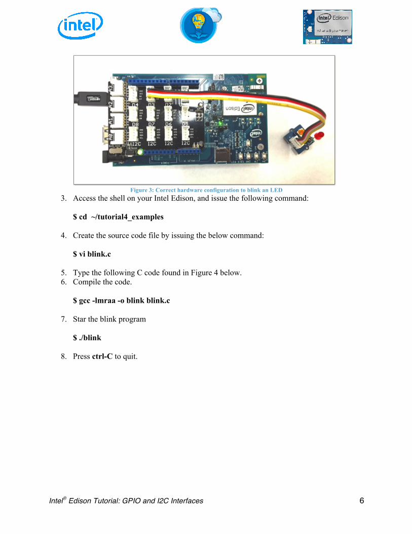
2. Insert the Grove Base Shield into the Edison board for Arduino and connect other components as shown in the pictures below. Please be attentive to the below diagram. If the component is connected to an incorrect interface, the system will not perform as desired. For example, if you connect the LED to D4 by mistake instead of D3, the LED will not emit light if you do not correct for this difference in ports in your C-code.
Intel® Edison Tutorial: GPIO and I2C Interfaces 6
Figure 3: Correct hardware configuration to blink an LED
3. Access the shell on your Intel Edison, and issue the following command: $ cd ~/tutorial4_examples
4. Create the source code file by issuing the below command: $ vi blink.c
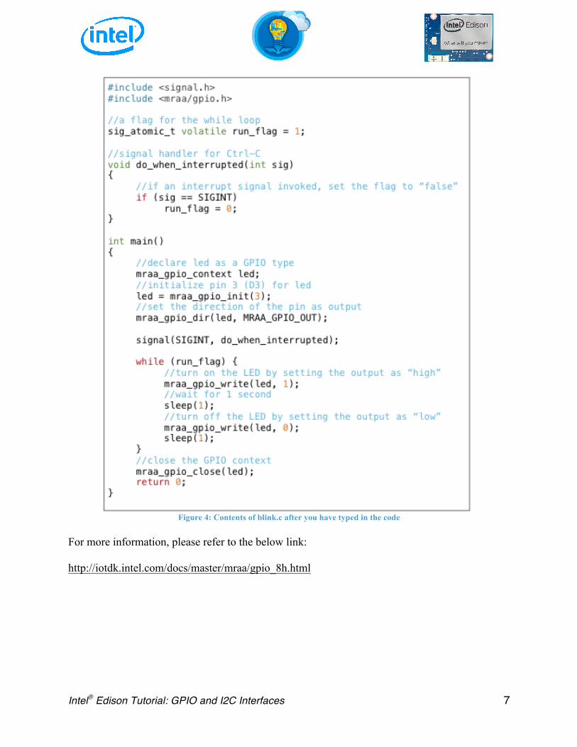
5. Type the following C code found in Figure 4 below. 6. Compile the code.
$ gcc -lmraa -o blink blink.c
7. Star the blink program $ ./blink
8. Press ctrl-C to quit.
Intel® Edison Tutorial: GPIO and I2C Interfaces 7
Figure 4: Contents of blink.c after you have typed in the code
For more information, please refer to the below link: http://iotdk.intel.com/docs/master/mraa/gpio_8h.html

Intel® Edison Tutorial: GPIO and I2C Interfaces 8
Polling and Interrupts There are two main ways for computing systems such as the Intel Edison to read data from a sensor: polling and interrupts. For a brief description on these methods, please consult the table and reference links below:
Polling Interrupts
Description Computing system is responsible for
requesting data from external peripherals.
Peripheral device will notify computing system once data is ready.
Interrupts are given a priority.
Interrupts with higher priority will generally be serviced before
interrupts with a lower priority.
In some situations, a higher priority interrupt can cause the computing system to stop servicing a lower
priority interrupt (or task) until the higher priority interrupt is serviced.
Pros Simple – does not require additional hardware support. Programming is
simple.
Efficient – When a device is ready to send data, the computing system will
be immediately notified.
Cons
Inefficient – requesting data from a device when the device is not ready to
send data wastes time and energy.
Loss of data – if the computing system does not request data when the device generates it, the data can
potentially be lost.
Complex – Programming becomes more complex. Requires additional
hardware and software support.
• https://en.wikipedia.org/wiki/Interrupt • https://en.wikipedia.org/wiki/Polling_(computer_science) • http://www.science.unitn.it/~fiorella/guidelinux/tlk/node86.html • http://www.electronics-base.com/useful-info/software-related/90-polling-vs-interrupt
Intel® Edison Tutorial: GPIO and I2C Interfaces 9
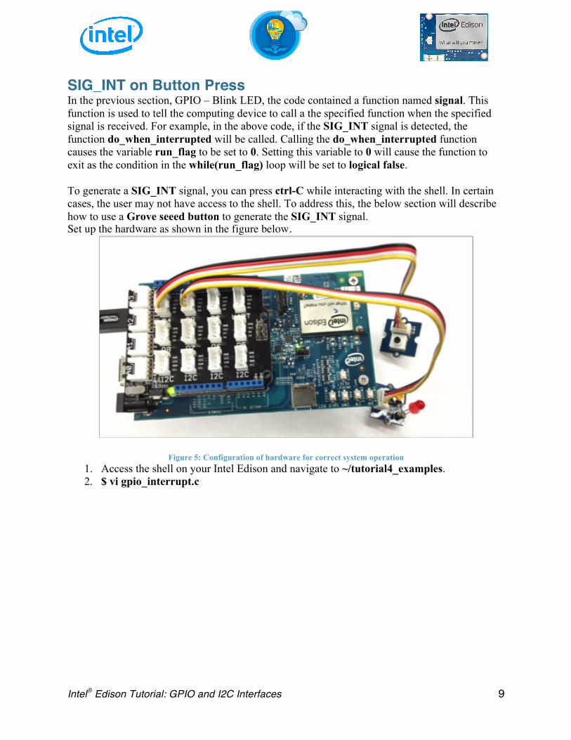
SIG_INT on Button Press In the previous section, GPIO – Blink LED, the code contained a function named signal. This function is used to tell the computing device to call a the specified function when the specified signal is received. For example, in the above code, if the SIG_INT signal is detected, the function do_when_interrupted will be called. Calling the do_when_interrupted function causes the variable run_flag to be set to 0. Setting this variable to 0 will cause the function to exit as the condition in the while(run_flag) loop will be set to logical false. To generate a SIG_INT signal, you can press ctrl-C while interacting with the shell. In certain cases, the user may not have access to the shell. To address this, the below section will describe how to use a Grove seeed button to generate the SIG_INT signal. Set up the hardware as shown in the figure below.
Figure 5: Configuration of hardware for correct system operation 1. Access the shell on your Intel Edison and navigate to ~/tutorial4_examples. 2. $ vi gpio_interrupt.c

Intel® Edison Tutorial: GPIO and I2C Interfaces 10
3. Type the below code into the file.
Figure 6: File contents of gpio_interrupt.c after entering the code
4. $ gcc -lmraa -o gpio_interrupt gpio_interrupt.c 5. $ ./gpio_interrupt 6. Press the button. As you can see, the program exits when you press the button. 7. Instead of generating the SIG_INT signal on a rising edge, let’s try to generate the signal
on a falling edge. Follow the below steps to make this change. 8. $ vi gpio_interrupt.c
Intel® Edison Tutorial: GPIO and I2C Interfaces 11
9. Modify the lines that read: mraa_gpio_isr(button, MRAA_GPIO_EDGE_RISING,
&do_when_interrupted, NULL); such that they now read: mraa_gpio_isr(button, MRAA_GPIO_EDGE_FALLING,
&do_when_interrupted, NULL);
10. $ gcc -lmraa -o gpio_interrupt gpio_interrupt.c 11. $ ./gpio_interrupt 12. Press and hold the button for a few seconds. 13. Release the button. The program exits when you release the button.
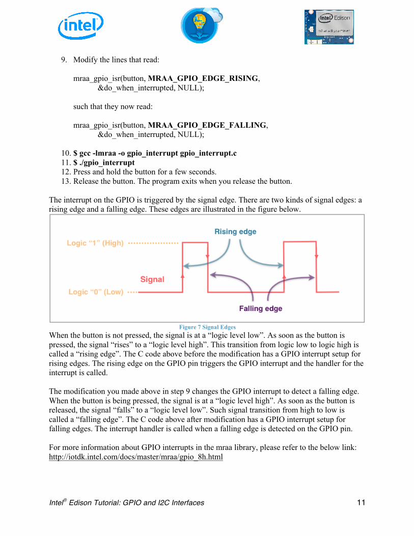
The interrupt on the GPIO is triggered by the signal edge. There are two kinds of signal edges: a rising edge and a falling edge. These edges are illustrated in the figure below.
Figure 7 Signal Edges When the button is not pressed, the signal is at a “logic level low”. As soon as the button is pressed, the signal “rises” to a “logic level high”. This transition from logic low to logic high is called a “rising edge”. The C code above before the modification has a GPIO interrupt setup for rising edges. The rising edge on the GPIO pin triggers the GPIO interrupt and the handler for the interrupt is called. The modification you made above in step 9 changes the GPIO interrupt to detect a falling edge. When the button is being pressed, the signal is at a “logic level high”. As soon as the button is released, the signal “falls” to a “logic level low”. Such signal transition from high to low is called a “falling edge”. The C code above after modification has a GPIO interrupt setup for falling edges. The interrupt handler is called when a falling edge is detected on the GPIO pin. For more information about GPIO interrupts in the mraa library, please refer to the below link: http://iotdk.intel.com/docs/master/mraa/gpio_8h.html

Intel® Edison Tutorial: GPIO and I2C Interfaces 12
Analog Input To demonstrate how to read the analog input on the Edison, we will try the following example from Grove – Starter Kit for Arduino.
1. Assemble the Edison, a base shield, and a rotary angle sensor as shown in the picture below. The rotary angle sensor is a potentiometer, for more information please refer to the below link: https://en.wikipedia.org/wiki/Potentiometer
Figure 8: Correct hardware configuration for analog input example 2. Access the shell on your Intel Edison. 3. $ vi rotary.c 4. Type the following C code.
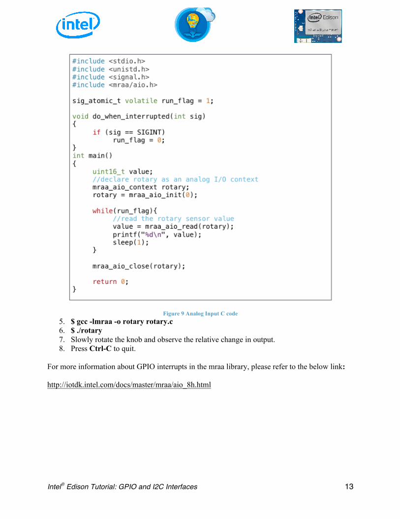
Intel® Edison Tutorial: GPIO and I2C Interfaces 13
Figure 9 Analog Input C code 5. $ gcc -lmraa -o rotary rotary.c 6. $ ./rotary 7. Slowly rotate the knob and observe the relative change in output. 8. Press Ctrl-C to quit.
For more information about GPIO interrupts in the mraa library, please refer to the below link: http://iotdk.intel.com/docs/master/mraa/aio_8h.html

Intel® Edison Tutorial: GPIO and I2C Interfaces 14
I2C (Inter-Integrated Circuit) I2C is a protocol designed for short distance communication between computing systems and peripheral devices. It is a multi-master, multi-slave, single ended, serial computer bus invented by Philips Semiconductor (now NXP Semiconductors). It uses two bi-directional, open drain lines, Serial Data Line (SDA) and Serial Clock Line (SCL). Some of the common data transfer rates are defined as: standard mode (100 kbits/sec), and low-speed mode (10 kbits/sec). Arbitrarily lower speeds can be used too. Some more recent I2C protocols also allow for the following modes: Fast mode (400 kbits/sec), Fast mode plus (Fm+, 1 Mbits/sec), and High speed mode (3.4 MBits/sec). The data transmission rate is limited by the address space and the total bus capacitance (400 pF).
Figure 10: Sample I2C schematic from Wikipedia
For more information, please refer to the below link: https://en.wikipedia.org/wiki/I%C2%B2C To demonstrate how I2C works, we will set up an I2C between the Edison and the Arduino Uno.
1. Make sure both the Edison and the Arduino Uno are completely powered off (No power is supplied).
2. Connect the Edison and the Arduino Uno as shown in the picture below.
Figure 11: I2C hardware setup

Intel® Edison Tutorial: GPIO and I2C Interfaces 15
1) Plug a cable into any of I2C port of the base shield on the Edison. 2) Connect three wires to three pins on other end of the cable.
• black (ground), white (SDA), yellow (SCL) 3) Connect these wires to the Arduino Uno.
• black (ground) to Arduino GND • white (SDA) to Arduino A4 (SDA) • yellow (SCL) to Arduino A5 (SCL)
3. Connect a USB cable to the Arduino Uno and your PC. 4. Open Arduino IDE. 5. Go to Tools -> Board and select Arduino Uno. 6. Go to Tools -> Port and select /dev/cu.usbmodemxxxxx (Arduino Uno). (Windows
users: select the COM port associated with the Arduino Uno) 7. Upload the following sketch to the Arduino Uno.
Figure 12 I2C Slave Arduino Sketch
8. Once uploading is done, unplug the USB cable. 9. Connect a micro USB cable to the multi-gadget USB port on the Edison and your PC. 10. Serial connect or SSH into the Edison. 11. $ cd tutorial4_examples 12. $ vi i2c.c

Intel® Edison Tutorial: GPIO and I2C Interfaces 16
13. Type the following C code.
Figure 13 I2C C Code
14. $ gcc -lmraa -o i2c i2c.c 15. Turn on the Arduino Uno by connecting the USB cable. 16. $ ./i2c
More information on the MRAA Library’s I2C API can be found at http://iotdk.intel.com/docs/master/mraa/i2c_8h.html


