Page 1
Intel® NUC Board NUC7i3BNB Technical Product Specification
January 2017
Order Number: J52707-001
Intel NUC Board NUC7i3BNB may contain design defects or errors known as errata that may cause the product to deviate from published
specifications. Current characterized errata, if any, are documented in Intel NUC Board NUC7i3BNB Specification Update.
Page 2
Revision History
Revision Revision History Date
001 First release of the Intel NUC Board NUC7i3BNB Technical Product Specification January 2017
Disclaimer
This product specification applies to only the standard Intel NUC Board with BIOS identifier BNKBL357.86A.
INFORMATION IN THIS DOCUMENT IS PROVIDED IN CONNECTION WITH INTEL® PRODUCTS. NO LICENSE, EXPRESS OR
IMPLIED, BY ESTOPPEL OR OTHERWISE, TO ANY INTELLECTUAL PROPERTY RIGHTS IS GRANTED BY THIS DOCUMENT. EXCEPT AS PROVIDED IN INTEL’S TERMS AND CONDITIONS OF SALE FOR SUCH PRODUCTS, INTEL ASSUMES NO LIABILITY WHATSOEVER, AND INTEL DISCLAIMS ANY EXPRESS OR IMPLIED WARRANTY, RELATING TO SALE AND/OR
USE OF INTEL PRODUCTS INCLUDING LIABILITY OR WARRANTIES RELATING TO FITNESS FOR A PARTICULAR PURPOSE, MERCHANTABILITY, OR INFRINGEMENT OF ANY PATENT, COPYRIGHT OR OTHER INTELLECTUAL PROPERTY RIGHT. UNLESS OTHERWISE AGREED IN WRITING BY INTEL, THE INTEL PRODUCTS ARE NOT DESIGNED NOR INTENDED FOR
ANY APPLICATION IN WHICH THE FAILURE OF THE INTEL PRODUCT COULD CREATE A SITUATION WHERE PERSONAL INJURY OR DEATH MAY OCCUR.
All Intel NUC Boards are evaluated as Information Technology Equipment (I.T.E.) for use in personal computers (PC) for
installation in homes, offices, schools, computer rooms, and similar locations. The suitability of this product for other PC or embedded non-PC applications or other environments, such as medical, industrial, alarm systems, test equipment, etc. may not be supported without further evaluation by Intel.
Intel Corporation may have patents or pending patent applications, trademarks, copyrights, or other intellectual property rights that relate to the presented subject matter. The furnishing of documents and other materials and information does not provide any license, express or implied, by estoppel or otherwise, to any such patents, trademarks, copyrights, or
other intellectual property rights.
Intel may make changes to specifications and product descriptions at any time, without notice.
Designers must not rely on the absence or characteristics of any features or instructions marked “reserved” or
“undefined.” Intel reserves these for future definition and shall have no responsibility whatsoever for conflicts or incompatibilities arising from future changes to them.
Intel processor numbers are not a measure of performance. Processor numbers differentiate features within each
processor family, not across different processor families: Go to: Learn About Intel® Processor Numbers
Intel NUC may contain design defects or errors known as errata, which may cause the product to deviate from published
specifications. Current characterized errata are available on request.
Contact your local Intel sales office or your distributor to obtain the latest specifications before placing your product order.
Intel, the Intel logo, Intel NUC and Intel Core are trademarks of Intel Corporation in the U.S. and/or other countries.
* Other names and brands may be claimed as the property of others.
The terms HDMI and HDMI High-Definition Multimedia Interface, and the HDMI Logo are trademarks or registered
trademarks of HDMI Licensing LLC in the United States and other countries
DisplayPort™ and the DisplayPort™ logo are trademarks owned by the Video Electronics Standards Association (VESA®) in the United States and other countries
Copyright 2017 Intel Corporation. All rights reserved.
Page 3
iii
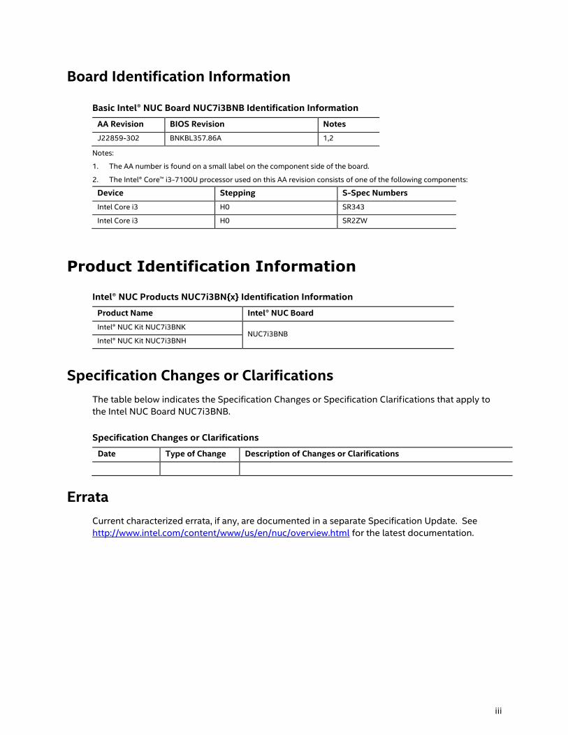
Board Identification Information
Basic Intel® NUC Board NUC7i3BNB Identification Information
AA Revision BIOS Revision Notes
J22859-302 BNKBL357.86A 1,2
Notes:
1. The AA number is found on a small label on the component side of the board.
2. The Intel® Core™ i3-7100U processor used on this AA revision consists of one of the following components:
Device Stepping S-Spec Numbers
Intel Core i3 H0 SR343
Intel Core i3 H0 SR2ZW
Product Identification Information
Intel® NUC Products NUC7i3BN{x} Identification Information
Product Name Intel® NUC Board
Intel® NUC Kit NUC7i3BNK NUC7i3BNB
Intel® NUC Kit NUC7i3BNH
Specification Changes or Clarifications
The table below indicates the Specification Changes or Specification Clarifications that apply to
the Intel NUC Board NUC7i3BNB.
Specification Changes or Clarifications
Date Type of Change Description of Changes or Clarifications
Errata
Current characterized errata, if any, are documented in a separate Specification Update. See
http://www.intel.com/content/www/us/en/nuc/overview.html for the latest documentation.
Page 4
Intel NUC Board NUC7i3BNB Technical Product Specification
iv
Preface
This Technical Product Specification (TPS) specifies the board layout, components, connectors,
power and environmental requirements, and the BIOS for Intel® NUC Board NUC7i3BNB.
Intended Audience
The TPS is intended to provide detailed, technical information about Intel® NUC Board
NUC7i3BNB and its components to the vendors, system integrators, and other engineers and
technicians who need this level of information. It is specifically not intended for general
audiences.
What This Document Contains
Chapter Description
1 A description of the hardware used on Intel NUC Board NUC7i3BNB
2 A map of the resources of the Intel NUC Board
3 The features supported by the BIOS Setup program
4 A description of the BIOS error messages, beep codes, and POST codes
5 The features of the Intel NUC kit NUC7i3BNK and NUC7i3BNH
Typographical Conventions
This section contains information about the conventions used in this specification. Not all of
these symbols and abbreviations appear in all specifications of this type.
Notes, Cautions, and Warnings
NOTE
Notes call attention to important information.
CAUTION
Cautions are included to help you avoid damaging hardware or losing data.
Page 5
v
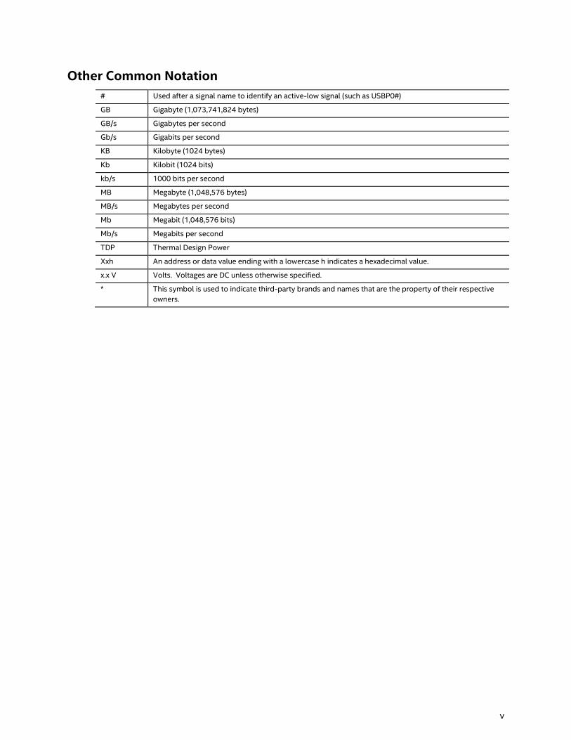
Other Common Notation
# Used after a signal name to identify an active-low signal (such as USBP0#)
GB Gigabyte (1,073,741,824 bytes)
GB/s Gigabytes per second
Gb/s Gigabits per second
KB Kilobyte (1024 bytes)
Kb Kilobit (1024 bits)
kb/s 1000 bits per second
MB Megabyte (1,048,576 bytes)
MB/s Megabytes per second
Mb Megabit (1,048,576 bits)
Mb/s Megabits per second
TDP Thermal Design Power
Xxh An address or data value ending with a lowercase h indicates a hexadecimal value.
x.x V Volts. Voltages are DC unless otherwise specified.
* This symbol is used to indicate third-party brands and names that are the property of their respective
owners.
Page 7
vii
Contents
Revision History ............................................................................................................... ii
Disclaimer .................................................................................................................................................................. ii
Board Identification Information ..................................................................................................................... iii
Product Identification Information ................................................................................................................. iii
Errata ........................................................................................................................................................................... iii
Preface .............................................................................................................................. iv
Intended Audience ................................................................................................................................................ iv
What This Document Contains ........................................................................................................................ iv
Typographical Conventions .............................................................................................................................. iv
Contents .......................................................................................................................... vii
1 Product Description ............................................................................................... 13
1.1 Overview ...................................................................................................................................................... 13
1.1.1 Feature Summary .................................................................................................................. 13
1.1.2 Board Layout (Top) ............................................................................................................... 15
1.1.3 Board Layout (Bottom) ........................................................................................................ 17
1.1.4 Block Diagram ......................................................................................................................... 19
1.2 Online Support .......................................................................................................................................... 20
1.3 Processor ..................................................................................................................................................... 20
1.4 System Memory ........................................................................................................................................ 21
1.5 Processor Graphics Subsystem .......................................................................................................... 23
1.5.1 Integrated Graphics .............................................................................................................. 23
1.6 USB ................................................................................................................................................................. 26
1.7 SATA Interface ........................................................................................................................................... 26
1.7.1 AHCI Mode ................................................................................................................................ 27
1.7.2 Intel® Rapid Storage Technology / SATA RAID ......................................................... 27
1.7.3 Intel® Next Generation Storage Acceleration ............................................................. 27
1.8 Real-Time Clock Subsystem ................................................................................................................ 28
1.9 Audio Subsystem ..................................................................................................................................... 28
1.9.1 Audio Subsystem Software ............................................................................................... 29
1.10 LAN Subsystem ......................................................................................................................................... 29
1.10.1 Intel® I219V Gigabit Ethernet Controller ..................................................................... 29
1.10.2 LAN Subsystem Software ................................................................................................... 29
1.10.3 RJ-45 LAN Connector with Integrated LEDs .............................................................. 30
1.10.4 Wireless Network Module .................................................................................................. 31
1.11 Hardware Management Subsystem ................................................................................................. 31
1.11.1 Hardware Monitoring ........................................................................................................... 31
1.11.2 Fan Monitoring ........................................................................................................................ 31
Page 8
viii
1.11.3 Thermal Solution ................................................................................................................... 31
1.12 Power Management ................................................................................................................................ 33
1.12.1 ACPI ............................................................................................................................................. 33
1.12.2 Hardware Support ................................................................................................................. 36
1.13 Intel Platform Security Technologies .............................................................................................. 38
1.13.1 Intel® Virtualization Technology ...................................................................................... 38
1.13.2 Intel® Platform Trust Technology ................................................................................... 38
2 Technical Reference ............................................................................................... 39
2.1 Memory Resources .................................................................................................................................. 39
2.1.1 Addressable Memory ........................................................................................................... 39
2.2 Connectors and Headers....................................................................................................................... 39
2.2.1 Front Panel Connectors ...................................................................................................... 40
2.2.2 Back Panel Connectors ....................................................................................................... 40
2.2.3 Headers and Connectors (Top) ........................................................................................ 41
2.2.4 Connectors and Headers (Bottom) ................................................................................. 42
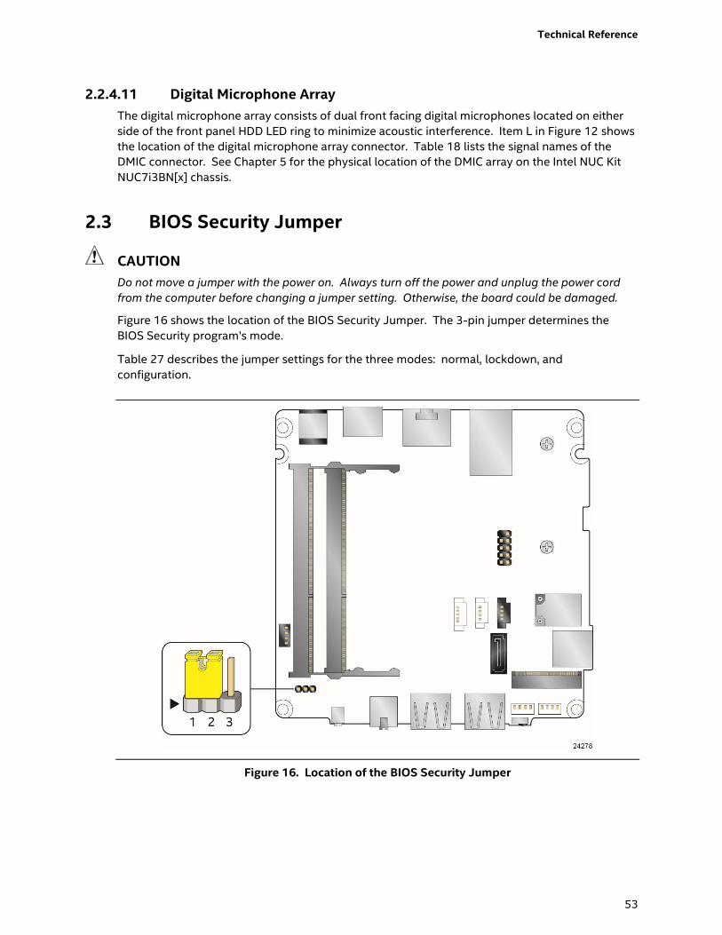
2.3 BIOS Security Jumper ............................................................................................................................ 53
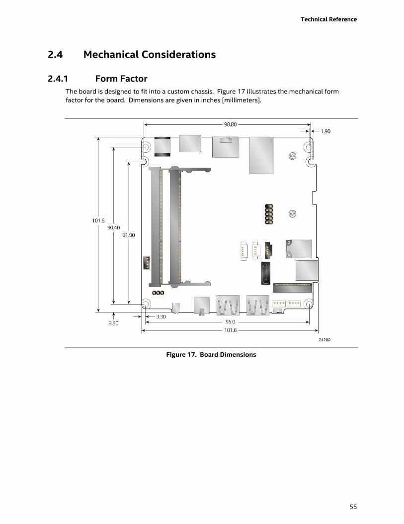
2.4 Mechanical Considerations .................................................................................................................. 55
2.4.1 Form Factor .............................................................................................................................. 55
2.5 Electrical Considerations ...................................................................................................................... 56
2.5.1 Power Supply Considerations .......................................................................................... 56
2.5.2 Fan Header Current Capability ......................................................................................... 56
2.6 Thermal Considerations ........................................................................................................................ 57
2.7 Reliability ..................................................................................................................................................... 62
2.8 Environmental ........................................................................................................................................... 62
3 Overview of BIOS Features ................................................................................... 63
3.1 Introduction ................................................................................................................................................ 63
3.2 BIOS Flash Memory Organization ..................................................................................................... 64
3.3 System Management BIOS (SMBIOS) .............................................................................................. 64
3.4 Legacy USB Support ............................................................................................................................... 64
3.5 BIOS Updates ............................................................................................................................................. 65
3.5.1 Language Support ................................................................................................................. 65
3.6 BIOS Recovery ........................................................................................................................................... 65
3.7 Boot Options .............................................................................................................................................. 67
3.7.1 Network Boot........................................................................................................................... 67
3.7.2 Booting Without Attached Devices ................................................................................ 67
3.7.3 Changing the Default Boot Device During POST ...................................................... 67
3.7.4 Power Button Menu .............................................................................................................. 68
3.8 Hard Disk Drive Password Security Feature .................................................................................. 69
3.9 BIOS Security Features .......................................................................................................................... 70
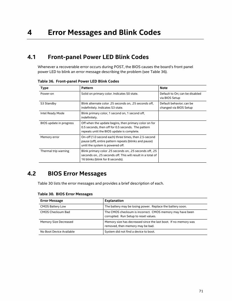
4 Error Messages and Blink Codes ......................................................................... 71
4.1 Front-panel Power LED Blink Codes ................................................................................................ 71
4.2 BIOS Error Messages ............................................................................................................................... 71
Page 9
Contents
ix
5 Intel NUC Kit Features ........................................................................................... 72
5.1 Chassis Front Panel Features .............................................................................................................. 72
5.3 Chassis Rear Panel Features ................................................................................................................ 74
Page 10
x
Figures
Figure 1. Major Board Components (Top) ....................................................................................................... 15
Figure 2. Major Board Components (Bottom) ................................................................................................ 17
Figure 3. Block Diagram ........................................................................................................................................... 19
Figure 4. Memory Channel and SO-DIMM Configuration.......................................................................... 22
Figure 5. 4-Pin 3.5 mm (1/8 inch) Audio Jack Pin Out ............................................................................... 28
Figure 6. LAN Connector LED Locations........................................................................................................... 30
Figure 7. Thermal Solution and Fan Header ................................................................................................... 32
Figure 8. Location of the Standby Power LED ............................................................................................... 37
Figure 9. Front Panel Connectors ........................................................................................................................ 40
Figure 10. Back Panel Connectors ...................................................................................................................... 40
Figure 11. Headers and Connectors (Top) ....................................................................................................... 41
Figure 12. Connectors and Headers (Bottom) ............................................................................................... 42
Figure 13. Connection Diagram for Front Panel Header (2.0 mm Pitch) ............................................ 47
Figure 14. Connection Diagram for the Internal USB 2.0 Single-Port Header (1.25 mm Pitch) 51
Figure 15. Location of the CIR Sensor ............................................................................................................... 51
Figure 16. Location of the BIOS Security Jumper ........................................................................................ 53
Figure 17. Board Dimensions ................................................................................................................................ 55
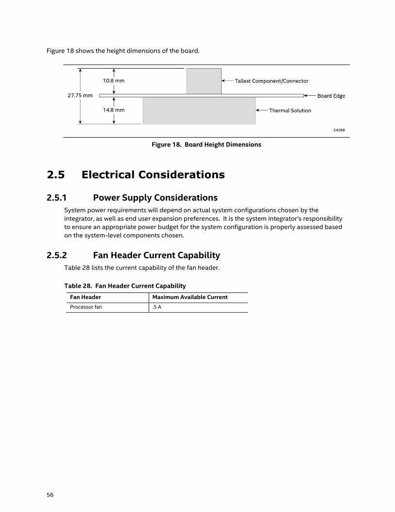
Figure 18. Board Height Dimensions ................................................................................................................. 56
Figure 19. Localized High Temperature Zones ............................................................................................. 58
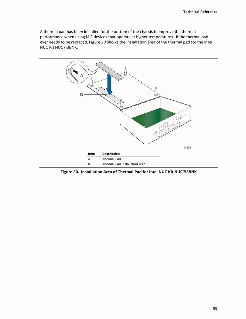
Figure 20. Installation Area of Thermal Pad for Intel NUC Kit NUC7i3BNK ...................................... 59
Figure 21. Installation area of Thermal Pad for Intel NUC Kit NUC7i3BNH ....................................... 60
Figure 22. Intel NUC Kit NUC7i3BNH Features – Front ............................................................................... 72
Figure 23. Intel NUC Kit NUC7i3BNK Features – Front ................................................................................ 73
Figure 24. Intel NUC Kit NUC7i3BNH Features – Rear ................................................................................. 74
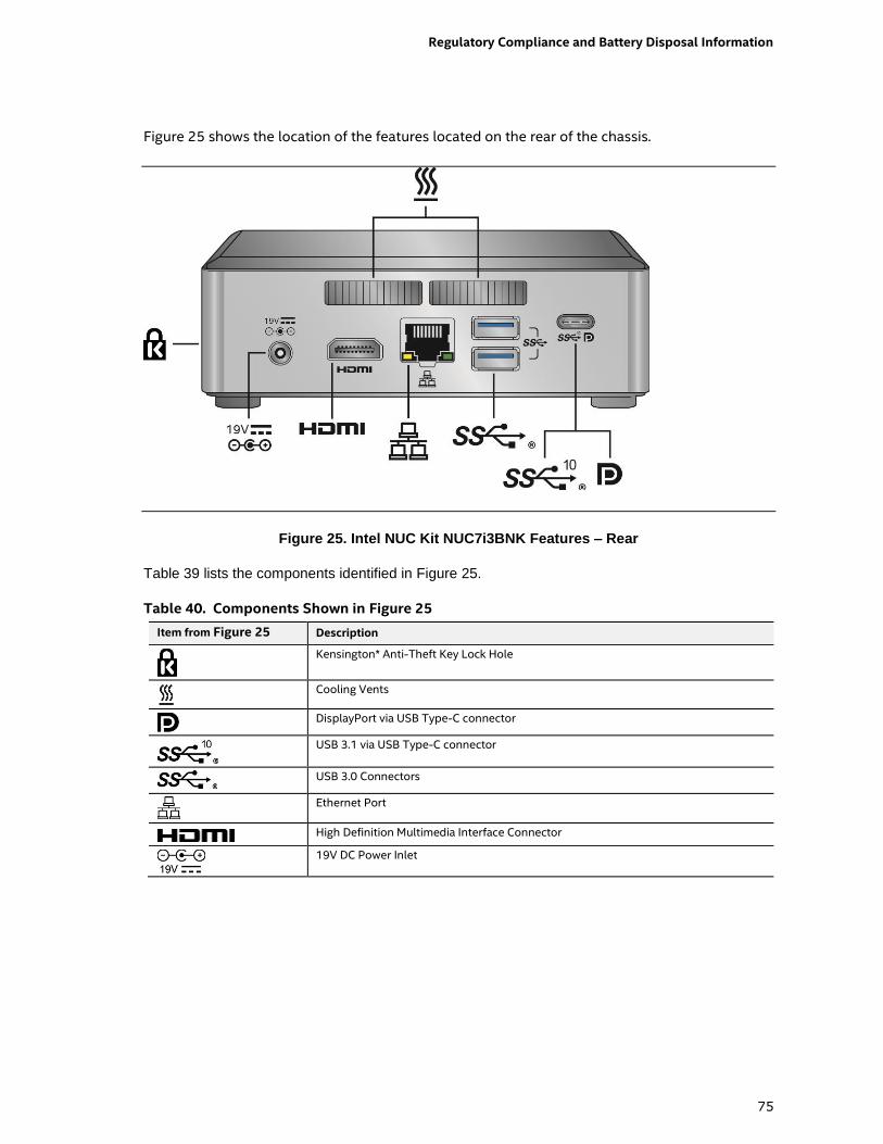
Figure 25. Intel NUC Kit NUC7i3BNK Features – Rear ................................................................................. 75
Tables
Table 1. Feature Summary ..................................................................................................................................... 13
Table 2. Components Shown in Figure 1 ......................................................................................................... 16
Table 3. Components Shown in Figure 2 ......................................................................................................... 18
Table 4. Supported Memory Configurations .................................................................................................. 21
Table 5. Unsupported Memory Configurations............................................................................................. 21
Table 6. DisplayPort Multi-Streaming Resolutions ...................................................................................... 24
Table 7. Multiple Display Configuration Maximum Resolutions ............................................................ 25
Table 8. Audio Formats Supported by the HDMI and USB Type-C Interfaces ................................. 25
Table 9. LAN Connector LED States ................................................................................................................... 30
Table 10. Effects of Pressing the Power Switch ............................................................................................ 33
Table 11. Power States and Targeted System Power ................................................................................. 34
Table 12. Wake-up Devices and Events ........................................................................................................... 35
Table 13. Headers and Connectors Shown in Figure 11 ........................................................................... 41
Table 14. Connectors and Headers Shown in Figure 12 ........................................................................... 43
Table 15. SATA Power Connector (1.25 mm pitch) ..................................................................................... 44
Page 11
Contents
xi
Table 16. Single-Port Internal USB 2.0 Header (1.25 mm pitch) ........................................................... 44
Table 17. M.2 2280 Module (key type M) Connector .................................................................................. 44
Table 18. Digital Microphone (DMICS) Array Connector (1.25 mm Pitch).......................................... 45
Table 19. Front Panel HDD LED Ring Connector (1.25 mm Pitch) ........................................................ 46
Table 20. CEC Header (1.25 mm pitch) ............................................................................................................. 46
Table 21. Front Panel Header (2.0 mm Pitch) ................................................................................................ 47
Table 22. States for a One-Color Power LED ................................................................................................. 48
Table 23. States for a Dual-Color Power LED ................................................................................................ 48
Table 24. SDXC Card Reader Connector .......................................................................................................... 49
Table 25. HDMI CEC expected behavior ............................................................................................................ 52
Table 26. Front Panel LED Ring ........................................................................................................................... 52
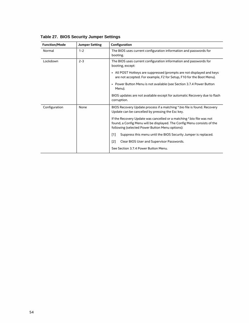
Table 27. BIOS Security Jumper Settings ........................................................................................................ 54
Table 28. Fan Header Current Capability ......................................................................................................... 56
Table 29. Thermal Considerations for Components ................................................................................... 61
Table 30. Tcontrol Values for Components ................................................................................................... 61
Table 31. Environmental Specifications ........................................................................................................... 62
Table 32. Acceptable Drives/Media Types for BIOS Recovery ............................................................... 65
Table 33. Boot Device Menu Options ................................................................................................................ 67
Table 34. Master Key and User Hard Drive Password Functions ........................................................... 69
Table 35. Supervisor and User Password Functions................................................................................... 70
Table 36. Front-panel Power LED Blink Codes ............................................................................................. 71
Table 37. Components Shown in Figure 22 ................................................................................................... 72
Table 38. Components Shown in Figure 23 ................................................................................................... 73
Table 39. Components Shown in Figure 24 ................................................................................................... 74
Table 40. Components Shown in Figure 25 ................................................................................................... 75
Page 13
13
1 Product Description
1.1 Overview
1.1.1 Feature Summary
Table 1 summarizes the major features of Intel® NUC Board NUC7i3BNB.
Table 1. Feature Summary
Form Factor 4.0 inches by 4.0 inches (101.60 millimeters by 101.60 millimeters)
Processor A soldered-down 7th generation Intel® Core™ i3-7100U dual-core processor with up to a
maximum 15 W TDP (if thermal margin available)
― Intel® HD Graphics 620
― Integrated memory controller
― Integrated PCH
Memory Two 260-pin 1.2 V DDR4 SDRAM Small Outline Dual Inline Memory Module (SO-DIMM)
sockets
Support for DDR4 1866/2133 MHz SO-DIMMs
Support for 4 Gb and 8 Gb memory technology
Support for up to 32 GB of system memory with two SO-DIMMs using 8 Gb memory
technology
Support for non-ECC memory
Support for 1.2 V low voltage JEDEC memory only
Note: 2 Gb memory technology (SDRAM Density) is not supported
Graphics Integrated graphics support for processors with Intel® Graphics Technology:
― One High Definition Multimedia Interface* (HDMI*) back panel connector
― One USB Type-C back panel connector
Audio Intel® High Definition (Intel® HD) Audio via the HDMI v2.0 and USB Type-C interfaces
through the processor
Realtek HD Audio via a stereo microphone/headphone 3.5 mm jack on the front panel
Digital microphone array (DMICS) connector (internal)
Storage SATA ports:
― One SATA 6.0 Gb/s port (black) for 2.5“ storage device
One SATA 6.0 Gb/s port is reserved for an M.2 storage module supporting M.2 2242 and
M.2 2280 (key type M and B+M) modules
Note: Supports key type M (PCI Express* x1/x2/x4 and SATA)
continued
Page 14
14
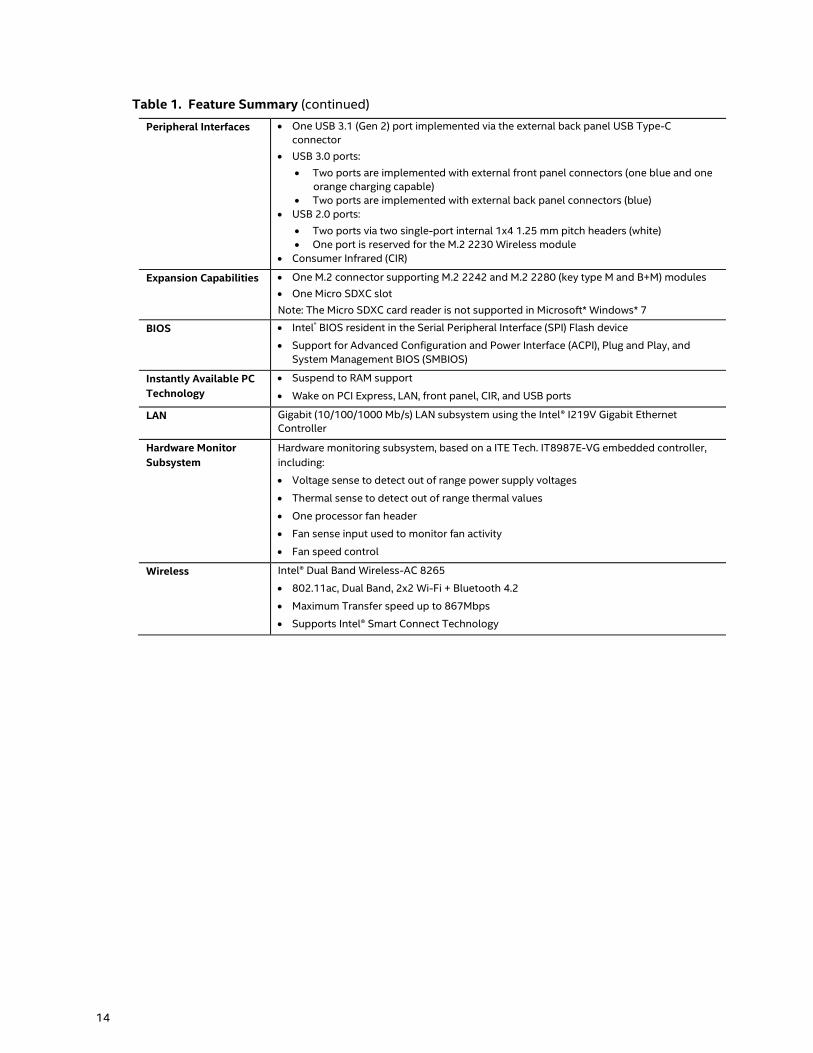
Table 1. Feature Summary (continued)
Peripheral Interfaces One USB 3.1 (Gen 2) port implemented via the external back panel USB Type-C
connector
USB 3.0 ports:
Two ports are implemented with external front panel connectors (one blue and one
orange charging capable)
Two ports are implemented with external back panel connectors (blue)
USB 2.0 ports:
Two ports via two single-port internal 1x4 1.25 mm pitch headers (white)
One port is reserved for the M.2 2230 Wireless module
Consumer Infrared (CIR)
Expansion Capabilities One M.2 connector supporting M.2 2242 and M.2 2280 (key type M and B+M) modules
One Micro SDXC slot
Note: The Micro SDXC card reader is not supported in Microsoft* Windows* 7
BIOS Intel® BIOS resident in the Serial Peripheral Interface (SPI) Flash device
Support for Advanced Configuration and Power Interface (ACPI), Plug and Play, and
System Management BIOS (SMBIOS)
Instantly Available PC
Technology
Suspend to RAM support
Wake on PCI Express, LAN, front panel, CIR, and USB ports
LAN Gigabit (10/100/1000 Mb/s) LAN subsystem using the Intel® I219V Gigabit Ethernet
Controller
Hardware Monitor
Subsystem
Hardware monitoring subsystem, based on a ITE Tech. IT8987E-VG embedded controller,
including:
Voltage sense to detect out of range power supply voltages
Thermal sense to detect out of range thermal values
One processor fan header
Fan sense input used to monitor fan activity
Fan speed control
Wireless Intel® Dual Band Wireless-AC 8265
802.11ac, Dual Band, 2x2 Wi-Fi + Bluetooth 4.2
Maximum Transfer speed up to 867Mbps
Supports Intel® Smart Connect Technology
Page 15
Product Description
15
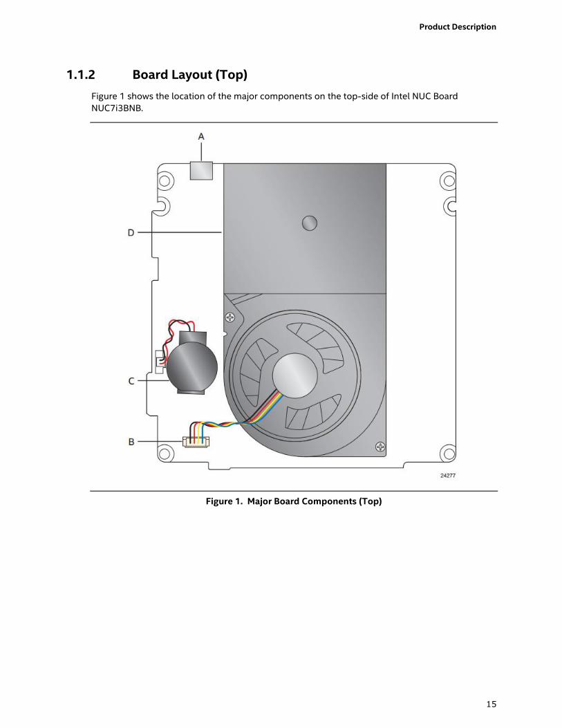
1.1.2 Board Layout (Top)
Figure 1 shows the location of the major components on the top-side of Intel NUC Board
NUC7i3BNB.
Figure 1. Major Board Components (Top)
Page 16
16
Table 2 lists the components identified in Figure 1.
Table 2. Components Shown in Figure 1
Item from Figure 1 Description
A USB Type-C connector
B Processor fan header
C Battery
D Thermal solution
Page 17
Product Description
17
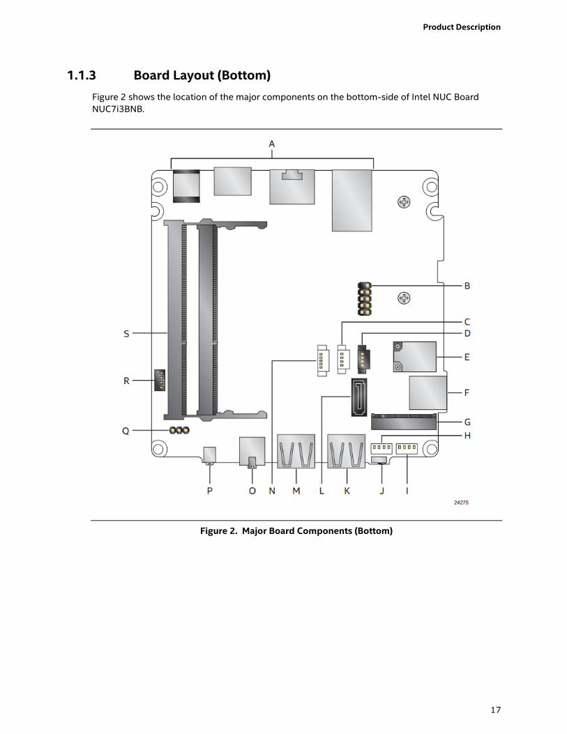
1.1.3 Board Layout (Bottom)
Figure 2 shows the location of the major components on the bottom-side of Intel NUC Board
NUC7i3BNB.
Figure 2. Major Board Components (Bottom)
Page 18
18
Table 3. Components Shown in Figure 2
Item from
Figure 2
Description
A Back panel connectors
B Front panel header
C Digital microphone array connector
D Front panel LED ring connector
E Intel Dual Band Wireless AC + Bluetooth 8265 module
F Micro SDXC slot
G M.2 connector (key type M and B+M) for 2242 and 2280 modules
H Front panel single-port USB 2.0 header (1.25 mm pitch)
I Front panel single-port USB 2.0 header (1.25 mm pitch)
J Consumer Infrared (CIR) sensor
K Front panel USB 3.0 connector (blue)
L SATA 6.0 Gb/s connector
M Front panel USB 3.0 connector (orange, charging)
N SATA power connector (1.25 mm pitch)
O Front panel stereo microphone/headphone jack
P Front panel power button
Q BIOS security jumper
R Consumer electronics control (CEC) header
S DDR4 SO-DIMM sockets
Page 19
Product Description
19
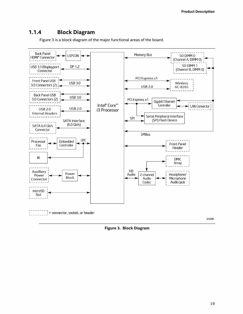
1.1.4 Block Diagram
Figure 3 is a block diagram of the major functional areas of the board.
Figure 3. Block Diagram
Page 20
20
1.2 Online Support To find information about… Visit this World Wide Web site:
Intel NUC Board NUC7i3BNB http://www.intel.com/NUC
Intel NUC Support http://www.intel.com/NUCSupport
Available configurations for Intel NUC Board
NUC7i3BNB
http://ark.intel.com
Product support page NUC7i3BNK http://www.intel.com/content/www/us/en/support/boards-and-
kits/intel-nuc-kits/intel-nuc-kit-nuc7i3bnk.html
Product support page NUC7i3BNH http://www.intel.com/content/www/us/en/support/boards-and-
kits/intel-nuc-kits/intel-nuc-kit-nuc7i3bnh.html
BIOS and driver updates http://downloadcenter.intel.com
BIOS and driver updates for NUC7i3BNK https://downloadcenter.intel.com/product/95069
BIOS and driver updates for NUC7i3BNH https://downloadcenter.intel.com/product/95066
Tested memory http://www.intel.com/content/www/us/en/support/boards-and-
kits/000020648.html
Integration information http://www.intel.com/NUCSupport
Processor datasheet http://ark.intel.com
1.3 Processor
A soldered-down 7th generation Intel® Core™ i3-7100U dual-core processor with up to a
maximum 15 W TDP (if thermal margin is available).
Intel® HD Graphics 620
Integrated memory controller
Integrated PCH
NOTE
There are specific requirements for providing power to the processor. Refer to Section 2.5.1 on
page 56 for information on power supply requirements.
Page 21
Product Description
21
1.4 System Memory
The board has two 260-pin SO-DIMM sockets and supports the following memory features:
1.2 V DDR4 SDRAM SO-DIMMs with gold plated contacts
Two independent memory channels with interleaved mode support
Unbuffered, single-sided or double-sided SO-DIMMs
32 GB maximum total system memory (with 8 Gb memory technology). Refer to Section 2.1.1
on page 39 for information on the total amount of addressable memory.
Minimum recommended total system memory: 2048 MB
Non-ECC SO-DIMMs
Serial Presence Detect
DDR4 1866/2133 MHz SDRAM SO-DIMMs
NOTE
To be fully compliant with all applicable DDR SDRAM memory specifications, the board should be
populated with SO-DIMMs that support the Serial Presence Detect (SPD) data structure. This
allows the BIOS to read the SPD data and program the chipset to accurately configure memory
settings for optimum performance. If non-SPD memory is installed, the BIOS will attempt to
correctly configure the memory settings, but performance and reliability may be impacted or the
SO-DIMMs may not function under the determined frequency.
NOTE
Intel NUC Board NUC7i3BNB supports only 4 Gb and 8 Gb memory technologies (also referred to
as “SDRAM density”). Table 4 lists the supported SO-DIMM configurations. Table 5 lists the SO-
DIMM configurations that are not supported.
Table 4. Supported Memory Configurations
SO-DIMM
Capacity
Configuration (Note)
SDRAM
Density
SDRAM Organization
Front-side/Back-side
Number of SDRAM
Devices
2048 MB SS 4 Gbit 512 M x4/empty 4
4096 MB DS 4 Gbit 512 M x4/512 M x4 8
4096 MB SS 8 Gbit 1024 M x4/empty 4
8192 MB DS 4 Gbit 512 M x8/512 M x8 16
8192 MB DS 8 Gbit 1024 M x4/1024 M x4 8
16384 MB DS 8 Gbit 1024 M X8/1024 M x8 16
Note: “DS” refers to double-sided memory modules and “SS” refers to single-sided memory modules.
Table 5. Unsupported Memory Configurations
SO-DIMM
Capacity
Configuration (Note)
SDRAM
Density
SDRAM Organization
Front-side/Back-side
Number of SDRAM
Devices
1024 MB SS 1 Gbit 128 M x8/empty 8
2048 MB DS 1 Gbit 128 M x8/128 M x8 16
2048 MB SS 2 Gbit 256 M x8/empty 8
4096 MB DS 2 Gbit 256 M x8/256 M x8 16
Note: “DS” refers to double-sided memory modules and “SS” refers to single-sided memory modules.
For information about… Refer to:
Tested Memory http://www.intel.com/content/www/us/en/support/boards-and-
kits/000020648.html
Page 22
22
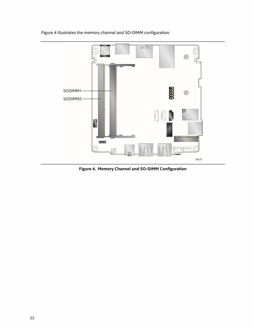
Figure 4 illustrates the memory channel and SO-DIMM configuration.
Figure 4. Memory Channel and SO-DIMM Configuration
Page 23
Product Description
23
1.5 Processor Graphics Subsystem
The board supports graphics through Intel HD Graphics.
1.5.1 Integrated Graphics
The board supports integrated graphics via the processor.
1.5.1.1 Intel® High Definition (Intel® HD) Graphics
The Intel HD graphics controller features the following:
3D Features
― DirectX* 12.1 support
― OpenGL* 5.0 support
― OpenCL* 2.1 support
Next Generation Intel® Clear Video Technology HD support is a collection of video playback
and enhancement features that improve the end user’s viewing experience
Encode/transcode HD content
Playback of high definition content including Blu-ray* disc
Superior image quality with sharper, more colorful images
DirectX* Video Acceleration (DXVA) support for accelerating video processing
Full AVC/VC1/MPEG2/HEVC HW Encode/Decode
Intel HD Graphics with Advanced Hardware Video Transcoding (Intel® Quick Sync Video)
NOTE
Intel Quick Sync Video is enabled by an appropriate software application.
1.5.1.2 Video Memory Allocation
Intel® Dynamic Video Memory Technology (DVMT) is a method for dynamically allocating system
memory for use as graphics memory to balance 2D/3D graphics and system performance. If your
computer is configured to use DVMT, graphics memory is allocated based on system
requirements and application demands (up to the configured maximum amount). When memory
is no longer needed by an application, the dynamically allocated portion of memory is returned to
the operating system for other uses.
1.5.1.3 High Definition Multimedia Interface* (HDMI*)
The HDMI port supports standard, enhanced, or high definition video, plus multi-channel digital
audio on a single cable. The port is compatible with all ATSC and DVB HDTV standards and
supports eight full range channels at 24-bit/96 kHz audio of lossless audio formats. The
maximum supported resolution is 4096 x 2160 @ 60 Hz, 24bpp. The HDMI port is compliant with
the HDMI 2.0 specification.
For information about Refer to
HDMI technology http://www.hdmi.org
Page 24
24
1.5.1.4 DisplayPort* via USB Type-C
DisplayPort is a digital communication interface that utilizes differential signaling to achieve a
high bandwidth bus interface designed to support connections between PCs and monitors,
projectors, and TV displays. DisplayPort is suitable for display connections between consumer
electronics devices such as high definition optical disc players, set top boxes, and TV displays.
The maximum supported resolution is 4096 x 2304 @ 60 Hz, 24bpp. DisplayPort via USB Type-C
connector is compliant with the DisplayPort 1.2 specification.
DisplayPort output supports Multi-Stream Transport (MST) which allows for multiple
independent video streams (daisy-chain connection with multiple monitors) over a single
DisplayPort. This will require the use of displays that support DisplayPort 1.2 and allow for this
feature.
For information about Refer to
DisplayPort technology http://www.displayport.org
1.5.1.4.1 DisplayPort 1.2 Multi-Stream Transport Daisy-Chaining
Table 6 lists the maximum resolutions available when using DisplayPort 1.2 Multi-Stream
Transport.
Table 6. DisplayPort Multi-Streaming Resolutions
DisplayPort Usage Models Monitor 1 Monitor 2 Monitor 3
3 Monitors 1920 x 1200 @ 60 Hz 1920 x 1080 @ 60 Hz 1920 x 1080 @ 60 Hz
2 Monitors 2560 x 1600 @ 60 Hz 2560 x 1600 @ 60 Hz
3 Monitors
(with DisplayPort 1.2 hub)
1920 x 1080 @ 60 Hz 1920 x 1080 @ 60 Hz 1920 x 1080 @ 60 Hz
Page 25
Product Description
25
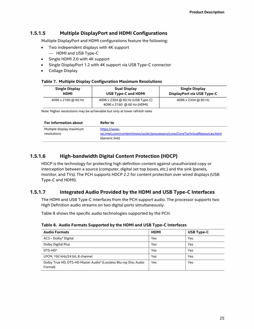
1.5.1.5 Multiple DisplayPort and HDMI Configurations
Multiple DisplayPort and HDMI configurations feature the following:
Two independent displays with 4K support
HDMI and USB Type-C
Single HDMI 2.0 with 4K support
Single DisplayPort 1.2 with 4K support via USB Type-C connector
Collage Display
Table 7. Multiple Display Configuration Maximum Resolutions
Single Display
HDMI
Dual Display
USB Type-C and HDMI
Single Display
DisplayPort via USB Type-C
4096 x 2160 @ 60 Hz 4096 x 2304 @ 60 Hz (USB Type-C)
4096 x 2160 @ 60 Hz (HDMI)
4096 x 2304 @ 60 Hz
Note: Higher resolutions may be achievable but only at lower refresh rates
For information about Refer to
Multiple display maximum
resolutions
https://www-
ssl.intel.com/content/www/us/en/processors/core/CoreTechnicalResources.html
(Generic link)
1.5.1.6 High-bandwidth Digital Content Protection (HDCP)
HDCP is the technology for protecting high definition content against unauthorized copy or
interception between a source (computer, digital set top boxes, etc.) and the sink (panels,
monitor, and TVs). The PCH supports HDCP 2.2 for content protection over wired displays (USB
Type-C and HDMI).
1.5.1.7 Integrated Audio Provided by the HDMI and USB Type-C Interfaces
The HDMI and USB Type-C interfaces from the PCH support audio. The processor supports two
High Definition audio streams on two digital ports simultaneously.
Table 8 shows the specific audio technologies supported by the PCH.
Table 8. Audio Formats Supported by the HDMI and USB Type-C Interfaces
Audio Formats HDMI USB Type-C
AC3 – Dolby* Digital Yes Yes
Dolby Digital Plus Yes Yes
DTS-HD* Yes Yes
LPCM, 192 kHz/24 bit, 8 channel Yes Yes
Dolby True HD, DTS-HD Master Audio* (Lossless Blu-ray Disc Audio
Format)
Yes Yes
Page 26
26
1.6 USB
The USB port arrangement is as follows:
USB 3.1 Gen 2 Type-C port implemented via the external back panel USB Type-C connector
(maximum current is 3A):
USB 3.0 ports (maximum current is 900 mA for each blue port, 1.5 A for the orange charging
port):
― Two ports are implemented with external front panel connectors (one blue and one
orange charging capable)
― Two ports are implemented with external back panel connectors (blue)
USB 2.0 ports (maximum current is 500 mA for each port of the white header (1 A total):
― Two ports via two single-port internal 1x4 1.25 mm pitch headers (white)
― One port is reserved for the M.2 2230 Wireless module
All the USB ports are high-speed, full-speed, and low-speed capable.
NOTE
Computer systems that have an unshielded cable attached to a USB port may not meet FCC
Class B requirements, even if no device is attached to the cable. Use a shielded cable that meets
the requirements for full-speed devices.
For information about Refer to
The location of the USB connectors on the back panel Figure 9, page 40
The location of the front panel USB headers Figure 2, page 17
1.7 SATA Interface
The board provides the following SATA interfaces:
SATA ports:
― One SATA 6.0 Gb/s port for 2.5” storage device
One SATA 6.0 Gb/s port is reserved for an M.2 storage module supporting M.2 2242 and
M.2 2280 (key type M and B+M) modules
The PCH provides independent SATA ports with a theoretical maximum transfer rate of 6 Gb/s. A
point-to-point interface is used for host to device connections.
Page 27
Product Description
27
1.7.1 AHCI Mode
The board supports AHCI storage mode.
NOTE
In order to use AHCI mode, AHCI must be enabled in the BIOS. Microsoft* Windows* 10 includes
the necessary AHCI drivers without the need to install separate AHCI drivers during the operating
system installation process; however, it is always good practice to update the AHCI drivers to the
latest available by Intel.
1.7.2 Intel® Rapid Storage Technology / SATA RAID
The PCH supports Intel® Rapid Storage Technology, providing both AHCI and integrated RAID
functionality. The RAID capability provides high-performance RAID 0 and 1 functionality on all
SATA ports. Other RAID features include hot spare support, SMART alerting, and RAID 0 auto
replace. Software components include an Option ROM for pre-boot configuration and boot
functionality, a Microsoft Windows compatible driver, and a user interface for configuration and
management of the RAID capability of the PCH.
NOTE
Intel Rapid Storage Technology / SATA RAID is only supported if an M.2 SATA SSD module is used
with the onboard SATA interface. RAID is not available when using M.2 PCIe SSD module and
onboard SATA interface.
1.7.3 Intel® Next Generation Storage Acceleration
Intel® Next Generation Storage Acceleration with Intel® Optane™ Technology is a disk caching
solution that can provide improved computer system performance with improved power savings. It
allows configuration of a computer system with the advantage of having HDDs for maximum
storage capacity and with Intel® Optane™ Technology for improved system performance.
For more information on Intel® Optane™ Technology, go to
http://www.intel.com/content/www/us/en/architecture-and-technology/non-volatile-
memory.html
NOTE
In order to use supported RAID and Intel Next Generation Storage Acceleration with Intel®
Optane™ Technology features, you must first enable RAID in the BIOS.
Page 28
28
1.8 Real-Time Clock Subsystem
A coin-cell battery (CR2032) powers the real-time clock and CMOS memory. When the computer
is not plugged into a wall socket, the battery has an estimated life of three years. When the
computer is plugged in, the standby current from the power supply extends the life of the battery.
The clock is accurate to 13 minutes/year at 25 ºC with 3.3 VSB applied via the power supply 5 V
STBY rail.
NOTE
If the battery and AC power fail, date and time values will be reset and the user will be notified
during the POST.
When the voltage drops below a certain level, the BIOS Setup program settings stored in CMOS
RAM (for example, the date and time) might not be accurate. Replace the battery with an
equivalent one. Figure 1 on page 15 shows the location of the battery.
1.9 Audio Subsystem
The audio subsystem supports the following features:
Digital microphone array (DMICS) connectors (internal)
Analog line-out/Analog Headphone/Analog Microphone (front panel jack)
Support for 44.1 kHz/48 kHz/96 kHz/192 kHz sample rates on all analog outputs
Support for 44.1 kHz/48 kHz/96 kHz sample rates on all analog inputs
Front Panel Audio Jack Support (see Figure 5 for 3.5 mm audio jack pin out):
― Speakers only (Stereo)
― Headphones only (Stereo)
― Microphone only (mono)
― Combo Headphone (Stereo)/Microphone (mono)
Pin Number Pin Name Description
1 Tip Left Audio Out
2 Ring Right Audio Out
3 Ring Common/Ground
4 Sleeve Audio In/MIC
Figure 5. 4-Pin 3.5 mm (1/8 inch) Audio Jack Pin Out
NOTE
The analog circuit of the front panel audio connector is designed to power headphones or
amplified speakers only. Poor audio quality occurs if passive (nonamplified) speakers are
connected to this output.
Page 29
Product Description
29
1.9.1 Audio Subsystem Software
Audio software and drivers are available from Intel’s World Wide Web site.
For information about Refer to
Obtaining Audio software and drivers http://downloadcenter.intel.com
1.10 LAN Subsystem
The LAN subsystem consists of the following:
Intel I219V Gigabit Ethernet Controller (10/100/1000 Mb/s)
RJ-45 LAN connector with integrated status LEDs
Additional features of the LAN subsystem include:
CSMA/CD protocol engine
LAN connect interface between the Processor and the LAN controller
Power management capabilities
― ACPI technology support
― LAN wake capabilities
LAN subsystem software
1.10.1 Intel® I219V Gigabit Ethernet Controller
The Intel I219V Gigabit Ethernet Controller supports the following features:
Compliant with the 1 Gb/s Ethernet 802.3, 802.3u, 802.3z, 802.3ab specifications
Multi-speed operation: 10/100/1000 Mb/s
Full-duplex operation at 10/100/1000 Mb/s; Half-duplex operation at 10/100 Mb/s
Flow control support compliant with the 802.3X specification as well as the specific operation
of asymmetrical flow control defined by 802.3z
VLAN support compliant with the 802.3q specification
Supports Jumbo Frames (up to 9 kB)
― IEEE 1588 supports (Precision Time Protocol)
MAC address filters: perfect match unicast filters, multicast hash filtering, broadcast filter, and
promiscuous mode
1.10.2 LAN Subsystem Software
LAN software and drivers are available from Intel’s World Wide Web site.
For information about Refer to
Obtaining LAN software and drivers http://downloadcenter.intel.com
Page 30
30
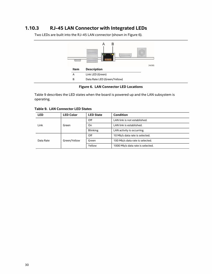
1.10.3 RJ-45 LAN Connector with Integrated LEDs
Two LEDs are built into the RJ-45 LAN connector (shown in Figure 6).
Item Description
A Link LED (Green)
B Data Rate LED (Green/Yellow)
Figure 6. LAN Connector LED Locations
Table 9 describes the LED states when the board is powered up and the LAN subsystem is
operating.
Table 9. LAN Connector LED States
LED LED Color LED State Condition
Link Green
Off LAN link is not established.
On LAN link is established.
Blinking LAN activity is occurring.
Data Rate Green/Yellow
Off 10 Mb/s data rate is selected.
Green 100 Mb/s data rate is selected.
Yellow 1000 Mb/s data rate is selected.
Page 31
Product Description
31
1.10.4 Wireless Network Module
The Intel Dual Band Wireless-AC 8265 module provides hi-speed wireless connectivity provided
with the following capabilities:
Compliant IEEE 802.11abgn, 802.11ac, 802.11d, 802.11e, 802.11i, 802.11h, 802.11w
specifications
Maximum bandwidth of 867 Mbps
Dual Mode Bluetooth* 4.2
OS certified with Microsoft Windows 10
Wi-Fi Direct* for peer to peer device connections
Wi-Fi Miracast Source
Authentication: WPA and WPA2, 802.1X (EAP-TLS, TTLS, PEAP, LEAP, EAP-FAST), EAP-SIM,
EAP-AKA
Encryption: 64-bit and 128-bit WEP, AES-CCMP, TKIP, WPA2, AES-CCMP
For information about Refer to
Obtaining WLAN software and drivers http://downloadcenter.intel.com
Full Specifications http://intel.com/wireless
1.11 Hardware Management Subsystem
The hardware management features enable the board to be compatible with the Wired for
Management (WfM) specification. The board has several hardware management features,
including thermal and voltage monitoring.
For information about Refer to
Wired for Management (WfM) Specification www.intel.com/design/archives/wfm/
1.11.1 Hardware Monitoring
The hardware monitoring and fan control subsystem is based on an ITE Tech. IT8987E-VG
embedded controller, which supports the following:
Processor and system ambient temperature monitoring
Chassis fan speed monitoring
Voltage monitoring of CPU IO Vcc (+Vccio), Memory Vcc (V_SM), CPU IN Vcc (+Vccp)
SMBus interface
1.11.2 Fan Monitoring
Fan monitoring can be implemented using third-party software.
1.11.3 Thermal Solution
Figure 7 shows the location of the thermal solution and processor fan header.
Page 32
32
Item Description
A Processor fan header
B Thermal solution
Figure 7. Thermal Solution and Fan Header
Page 33
Product Description
33
1.12 Power Management
Power management is implemented at several levels, including:
Software support through Advanced Configuration and Power Interface (ACPI)
Hardware support:
― Power Input
― Instantly Available PC technology
― LAN wake capabilities
― Wake from USB
― WAKE# signal wake-up support
― Wake from S5
― Wake from CIR
― +5 V Standby Power Indicator LED
1.12.1 ACPI
ACPI gives the operating system direct control over the power management and Plug and Play
functions of a computer. The use of ACPI with this board requires an operating system that
provides full ACPI support. ACPI features include:
Plug and Play (including bus and device enumeration)
Power management control of individual devices, add-in boards (some add-in boards may
require an ACPI-aware driver), video displays, and hard disk drives
Methods for achieving less than 15-watt system operation in the power-on/standby
sleeping state
A Soft-off feature that enables the operating system to power-off the computer
Support for multiple wake-up events (see Table 12 on page 35)
Support for a front panel power and sleep mode switch
Table 10 lists the system states based on how long the power switch is pressed, depending on
how ACPI is configured with an ACPI-aware operating system.
Table 10. Effects of Pressing the Power Switch
If the system is in this state… …and the power switch is pressed for …the system enters this state
Off
(ACPI G2/G5 – Soft off)
Less than four seconds Power-on
(ACPI G0 – working state)
On
(ACPI G0 – working state)
Less than four seconds Soft-off/Standby
(ACPI G1 – sleeping state) Note
On
(ACPI G0 – working state)
More than six seconds Fail safe power-off
(ACPI G2/G5 – Soft off)
Sleep
(ACPI G1 – sleeping state)
Less than four seconds Wake-up
(ACPI G0 – working state)
Sleep
(ACPI G1 – sleeping state)
More than six seconds Power-off
(ACPI G2/G5 – Soft off)
Note: Depending on power management settings in the operating system.
Page 34
34
1.12.1.1 System States and Power States
Under ACPI, the operating system directs all system and device power state transitions. The
operating system puts devices in and out of low-power states based on user preferences and
knowledge of how devices are being used by applications. Devices that are not being used can be
turned off. The operating system uses information from applications and user settings to put the
system as a whole into a low-power state.
Table 11 lists the power states supported by the board along with the associated system power
targets. See the ACPI specification for a complete description of the various system and power
states.
Table 11. Power States and Targeted System Power
Global States
Sleeping States
Processor
States
Device States
Targeted System
Power (Note 1)
G0 – working
state
S0 – working C0 – working D0 – working state. Full power > 30 W
G1 – sleeping
state
S3 – Suspend to RAM.
Context saved to
RAM.
No power D3 – no power
except for wake-up
logic.
Power < 5 W (Note 2)
G1 – sleeping
state
S4 – Suspend to disk.
Context saved to disk.
No power D3 – no power
except for wake-up
logic.
Power < 5 W (Note 2)
G2/S5 S5 – Soft off. Context
not saved. Cold boot
is required.
No power D3 – no power
except for wake-up
logic.
Power < 5 W (Note 2)
G3 – mechanical
off
AC power is
disconnected
from the
computer.
No power to the
system.
No power D3 – no power for
wake-up logic,
except when
provided by battery
or external source.
No power to the system.
Service can be performed
safely.
Notes:
1. Total system power is dependent on the system configuration, including add-in boards and peripherals powered by
the system chassis’ power supply.
2. Dependent on the standby power consumption of wake-up devices used in the system.
Page 35
Product Description
35
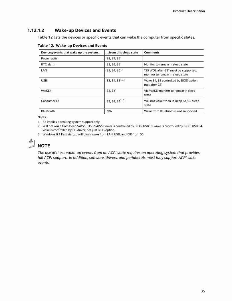
1.12.1.2 Wake-up Devices and Events
Table 12 lists the devices or specific events that can wake the computer from specific states.
Table 12. Wake-up Devices and Events
Devices/events that wake up the system… …from this sleep state Comments
Power switch S3, S4, S51
RTC alarm S3, S4, S51 Monitor to remain in sleep state
LAN S3, S4, S51, 3 “S5 WOL after G3” must be supported;
monitor to remain in sleep state
USB S3, S4, S51, 2, 3 Wake S4, S5 controlled by BIOS option
(not after G3)
WAKE# S3, S41 Via WAKE; monitor to remain in sleep
state
Consumer IR S3, S4, S51, 3 Will not wake when in Deep S4/S5 sleep
state
Bluetooth N/A Wake from Bluetooth is not supported
Notes:
1. S4 implies operating system support only.
2. Will not wake from Deep S4/S5. USB S4/S5 Power is controlled by BIOS. USB S5 wake is controlled by BIOS. USB S4
wake is controlled by OS driver, not just BIOS option.
3. Windows 8.1 Fast startup will block wake from LAN, USB, and CIR from S5.
NOTE
The use of these wake-up events from an ACPI state requires an operating system that provides
full ACPI support. In addition, software, drivers, and peripherals must fully support ACPI wake
events.
Page 36
36
1.12.2 Hardware Support
The board provides several power management hardware features, including:
Wake from Power Button signal
Instantly Available PC technology
LAN wake capabilities
Wake from USB (not after G3)
WAKE# signal wake-up support
Wake from S5
Wake from CIR
+5 V Standby Power Indicator LED
NOTE
The use of Wake from USB from an ACPI state requires an operating system that provides full
ACPI support.
1.12.2.1 Power Input
When resuming from an AC power failure, the computer returns to the power state it was in
before power was interrupted (on or off). The computer’s response can be set using the Last
Power State feature in the BIOS Setup program’s Boot menu.
1.12.2.2 Instantly Available PC Technology
Instantly Available PC technology enables the board to enter the ACPI S3 (Suspend-to-RAM)
sleep-state. While in the S3 sleep-state, the computer will appear to be off (the power supply is
only supplying Standby power, and the front panel LED will be amber or secondary color if dual
colored, or off if single colored.) When signaled by a wake-up device or event, the system quickly
returns to its last known wake state. Table 12 on page 35 lists the devices and events that can
wake the computer from the S3 state.
The use of Instantly Available PC technology requires operating system support and drivers for
any installed M.2 add-in card.
1.12.2.3 LAN Wake Capabilities
LAN wake capabilities enable remote wake-up of the computer through a network. The LAN
subsystem monitors network traffic at the Media Independent Interface. Upon detecting a Magic
Packet* frame, the LAN subsystem asserts a wake-up signal that powers up the computer.
1.12.2.4 Wake from USB
USB bus activity wakes the computer from an ACPI S3 state (not after G3).
NOTE
Wake from USB requires the use of a USB peripheral that supports Wake from USB.
Page 37
Product Description
37
1.12.2.5 WAKE# Signal Wake-up Support
When the WAKE# signal on the PCI Express bus is asserted, the computer wakes from an ACPI S3
or S4 state.
1.12.2.6 Wake from S5
When the RTC Date and Time is set in the BIOS, the computer will automatically wake from an
ACPI S5 state.
1.12.2.7 Wake from Consumer IR
CIR activity wakes the computer from an ACPI S3, S4, or S5 state.
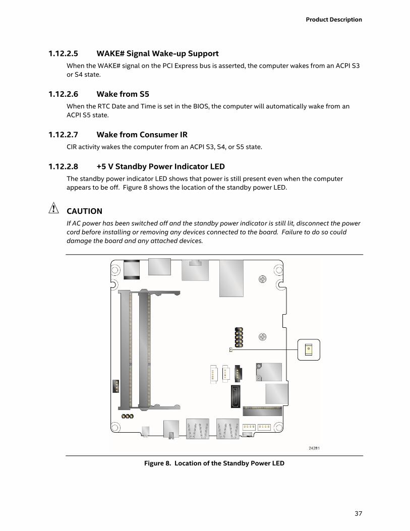
1.12.2.8 +5 V Standby Power Indicator LED
The standby power indicator LED shows that power is still present even when the computer
appears to be off. Figure 8 shows the location of the standby power LED.
CAUTION
If AC power has been switched off and the standby power indicator is still lit, disconnect the power
cord before installing or removing any devices connected to the board. Failure to do so could
damage the board and any attached devices.
Figure 8. Location of the Standby Power LED
Page 38
38
1.13 Intel Platform Security Technologies
Intel platform security technologies provides tools and resources to help the user protect their
information by creating a safer computing environment.
NOTE
Software with security capability is required to take advantage of Intel platform security
technologies.
1.13.1 Intel® Virtualization Technology Intel Virtualization Technology (Intel® VT) is a hardware-assisted technology that, when
combined with software-based virtualization solutions, provides maximum system utilization by
consolidating multiple environments into a single server or client.
NOTE
A processor with Intel VT does not guarantee that virtualization will work on your system. Intel VT
requires a computer system with a chipset, BIOS, enabling software and/or operating system,
device drivers, and applications designed for this feature.
For information about Refer to
Intel Virtualization Technology http://www.intel.com/technology/virtualization/technology.htm
1.13.2 Intel® Platform Trust Technology
Intel® Platform Trust Technology (Intel® PTT) is a platform functionality for credential storage and
key management. Intel® PTT supports Microsoft* BitLocker* Drive Encryption for hard drive
encryption and supports all Microsoft requirements for firmware Trusted Platform Module (fTPM)
2.0.
NOTE
Support for fTPM version 2.0 requires a UEFI-enabled operating system, such as Microsoft*
Windows* 10.
CAUTION
BIOS recovery using the BIOS security jumper clears Intel® Platform Trust Technology (Intel® PTT)
keys. These keys will not be restored after the BIOS recovery.
For information about Refer to
Intel Platform Trust Technology http://www.intel.com/content/dam/www/public/us/en/documents
/white-papers/enterprise-security-platform-trust-technology-
white-paper.pdf
Page 39
39
2 Technical Reference
2.1 Memory Resources
2.1.1 Addressable Memory
The board utilizes 32 GB of addressable system memory. Typically the address space that is
allocated for PCI Conventional bus add-in cards, PCI Express configuration space, BIOS (SPI Flash
device), and chipset overhead resides above the top of DRAM (total system memory). On a
system that has 32 GB of system memory installed, it is not possible to use all of the installed
memory due to system address space being allocated for other system critical functions. These
functions include the following:
BIOS/SPI Flash device (64 Mb)
Local APIC (19 MB)
Direct Media Interface (40 MB)
PCI Express configuration space (256 MB)
PCH base address registers PCI Express ports (up to 256 MB)
Memory-mapped I/O that is dynamically allocated for M.2 add-in cards (256 MB)
Integrated graphics shared memory (up to 512 MB; 64 MB by default)
The board provides the capability to reclaim the physical memory overlapped by the memory
mapped I/O logical address space. The board remaps physical memory from the top of usable
DRAM boundary to the 4 GB boundary to an equivalent sized logical address range located just
above the 4 GB boundary. All installed system memory can be used when there is no overlap of
system addresses.
2.2 Connectors and Headers
CAUTION
Only the following connectors and headers have overcurrent protection: back panel and front
panel USB.
The other internal connectors and headers are not overcurrent protected and should connect only
to devices inside the computer’s chassis, such as fans and internal peripherals. Do not use these
connectors or headers to power devices external to the computer’s chassis. A fault in the load
presented by the external devices could cause damage to the computer, the power cable, and the
external devices themselves.
Furthermore, improper connection of USB header single wire connectors may eventually overload
the overcurrent protection and cause damage to the board.
Page 40
40
This section describes the board’s connectors and headers. The connectors and headers can be
divided into these groups:
Front panel I/O connectors
Back panel I/O connectors
2.2.1 Front Panel Connectors
Figure 9 shows the location of the front panel connectors for the board.
Item Description
A Front panel power button
B Front panel Stereo
microphone/headphone jack
C USB 3.0 ports (orange charging
capable)
D USB 3.0 (blue)
E CIR
Figure 9. Front Panel Connectors
2.2.2 Back Panel Connectors
Figure 10 shows the location of the back panel connectors for the board.
Item Description
A USB Type-C connector
B USB 3.0 ports (blue)
C LAN
D HDMI connector
E 12-19 V DC input jack
Figure 10. Back Panel Connectors
Page 41
Technical Reference
41
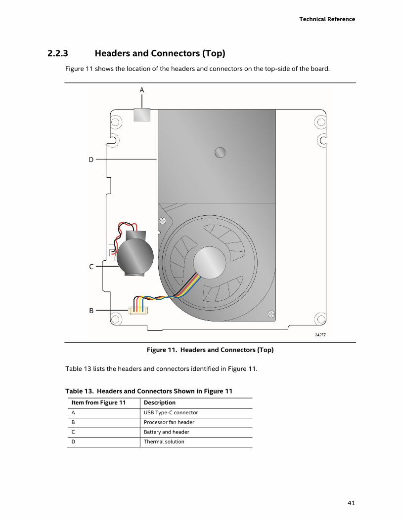
2.2.3 Headers and Connectors (Top)
Figure 11 shows the location of the headers and connectors on the top-side of the board.
Figure 11. Headers and Connectors (Top)
Table 13 lists the headers and connectors identified in Figure 11.
Table 13. Headers and Connectors Shown in Figure 11
Item from Figure 11 Description
A USB Type-C connector
B Processor fan header
C Battery and header
D Thermal solution
Page 42
42
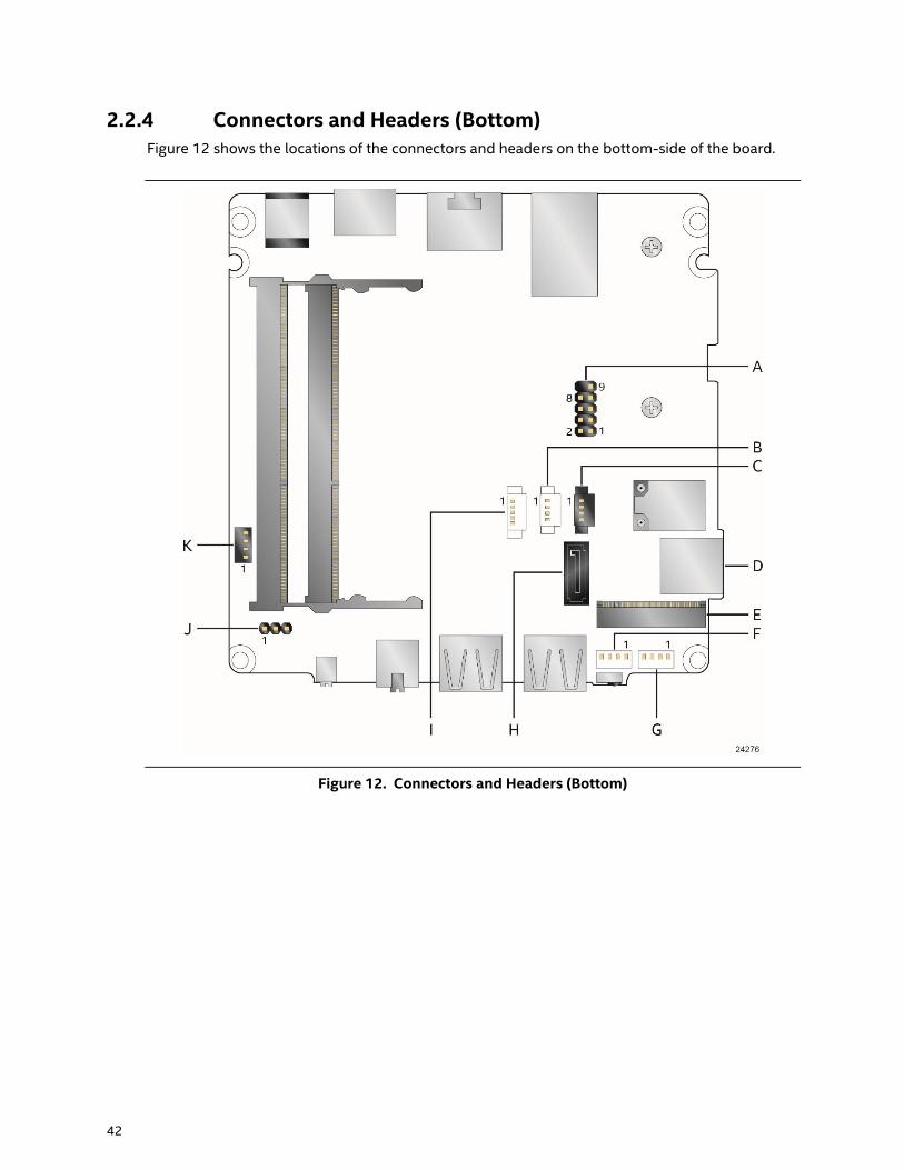
2.2.4 Connectors and Headers (Bottom)
Figure 12 shows the locations of the connectors and headers on the bottom-side of the board.
Figure 12. Connectors and Headers (Bottom)
Page 43
Technical Reference
43
Table 14 lists the connectors and headers identified in Figure 12.
Table 14. Connectors and Headers Shown in Figure 12
Item from
Figure 12
Description
A Front panel header
B Digital microphone array connector
C Front panel LED ring connector
D Micro SDXC slot
E M.2 connector (key type M) for 2242 and 2280 modules
F Front panel single-port USB 2.0 header (1.25 mm pitch)
G Front panel single-port USB 2.0 header (1.25 mm pitch)
H SATA 6.0 Gb/s connector
I SATA power connector (1.25 mm pitch)
J BIOS security jumper
K Consumer electronics control (CEC) header
Page 44
44
2.2.4.1 Signal Tables for the Connectors and Headers
Table 15. SATA Power Connector (1.25 mm pitch)
Pin Signal Name
1 +5 V
2 +5 V
3 +3.3 V
4 GND
5 GND
NOTE
Connector is Molex* part number 53398-0571, 1.25 mm pitch PicoBlade* header, surface mount,
vertical, lead-free, 5 circuits.
Table 16. Single-Port Internal USB 2.0 Header (1.25 mm pitch)
Pin Signal Name Pin Signal Name
1 +5 V DC 2 D-
3 D+ 4 Ground
NOTE
Connector is Molex part number 53398-0471, 1.25 mm pitch PicoBlade header, surface mount,
vertical, lead-free, 4 circuits.
Table 17. M.2 2280 Module (key type M) Connector
Pin Signal Name Pin Signal Name
74 3.3V 75 GND
72 3.3V 73 GND
70 3.3V 71 GND
68 SUSCLK(32kHz) (O)(0/3.3V) 69 PEDET (NC-PCIe/GND-SATA)
66 Connector Key 67 N/C
64 Connector Key 65 Connector Key
62 Connector Key 63 Connector Key
60 Connector Key 61 Connector Key
58 N/C 59 Connector Key
56 N/C 57 GND
continued
Page 45
Technical Reference
45
Table 17. M.2 2280 Module (key type M) Connector (continued)
Pin Signal Name Pin Signal Name
54 PEWAKE# (I/O)(0/3.3V) or N/C 55 REFCLKP
52 CLKREQ# (I/O)(0/3.3V) or N/C 53 REFCLKN
50 PERST# (O)(0/3.3V) or N/C 51 GND
48 N/C 49 PETp0/SATA-A+
46 N/C 47 PETn0/SATA-A-
44 N/C 45 GND
42 N/C 43 PERp0/SATA-B-
40 N/C 41 PERn0/SATA-B+
38 DEVSLP (O) 39 GND
36 N/C 37 PETp1
34 N/C 35 PETn1
32 N/C 33 GND
30 N/C 31 PERp1
28 N/C 29 PERn1
26 N/C 27 GND
24 N/C 25 PETp2
22 N/C 23 PETn2
20 N/C 21 GND
18 3.3V 19 PERp2
16 3.3V 17 PERn2
14 3.3V 15 GND
12 3.3V 13 PETp3
10 DAS/DSS# (I/O)/LED1# (I)(0/3.3V) 11 PETn3
8 N/C 9 GND
6 N/C 7 PERp3
4 3.3V 5 PERn3
2 3.3V 3 GND
1 GND
Table 18. Digital Microphone (DMICS) Array Connector (1.25 mm Pitch)
Pin Signal Name
1 Ground
2 +3.3 V DC (+3V3_DMIC)
3 Clock (DMIC_CLK)
4 Data (DMIC_DAT)
NOTE
Connector is Aces part number 50273-0047C-002, 1.25 mm pitch header, surface mount, vertical,
lead-free, 4 circuits.
Page 46
46
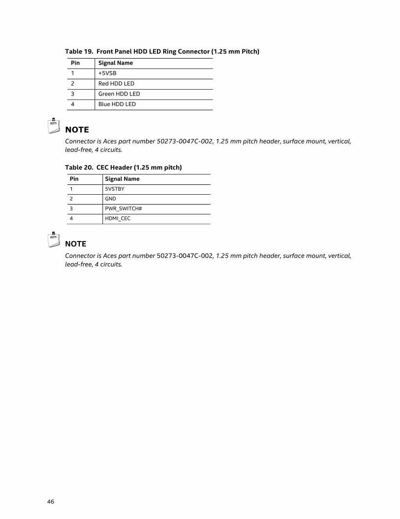
Table 19. Front Panel HDD LED Ring Connector (1.25 mm Pitch)
Pin Signal Name
1 +5VSB
2 Red HDD LED
3 Green HDD LED
4 Blue HDD LED
NOTE
Connector is Aces part number 50273-0047C-002, 1.25 mm pitch header, surface mount, vertical,
lead-free, 4 circuits.
Table 20. CEC Header (1.25 mm pitch)
Pin Signal Name
1 5VSTBY
2 GND
3 PWR_SWITCH#
4 HDMI_CEC
NOTE
Connector is Aces part number 50273-0047C-002, 1.25 mm pitch header, surface mount, vertical,
lead-free, 4 circuits.
Page 47
Technical Reference
47
2.2.4.2 Add-in Card Connectors
The board supports M.2 2242 and 2280 (key type M) modules.
Supports M.2 SSD SATA drives
― Maximum bandwidth is approximately 540 MB/s
Supports M.2 SSD Gen 3 PCIe AHCI and NVMe drives (PCIe x1, x2, and x4)
― Using PCIe x4 M.2 SSD maximum bandwidth is approximately 4000 MB/s
2.2.4.3 USB Type-C connector
The board has several features that are supported via the USB Type-C connector.
Supports USB 3.1 Gen 2.0
― Maximum bandwidth is approximately 10 Gbit/s
Supports Display port 1.2
― Maximum bandwidth is approximately 17.28 Gbit/s
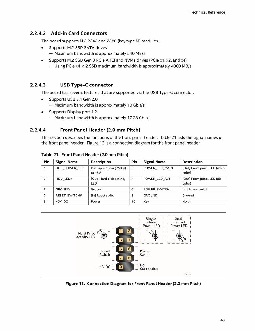
2.2.4.4 Front Panel Header (2.0 mm Pitch)
This section describes the functions of the front panel header. Table 21 lists the signal names of
the front panel header. Figure 13 is a connection diagram for the front panel header.
Table 21. Front Panel Header (2.0 mm Pitch)
Pin Signal Name Description Pin Signal Name Description
1 HDD_POWER_LED Pull-up resistor (750 Ω)
to +5V
2 POWER_LED_MAIN [Out] Front panel LED (main
color)
3 HDD_LED# [Out] Hard disk activity
LED
4 POWER_LED_ALT [Out] Front panel LED (alt
color)
5 GROUND Ground 6 POWER_SWITCH# [In] Power switch
7 RESET_SWITCH# [In] Reset switch 8 GROUND Ground
9 +5V_DC Power 10 Key No pin
Figure 13. Connection Diagram for Front Panel Header (2.0 mm Pitch)
Page 48
48
2.2.4.4.1 Hard Drive Activity LED Header
Pins 1 and 3 can be connected to an LED to provide a visual indicator that data is being read from
or written to a hard drive. Proper LED function requires a SATA hard drive or optical drive
connected to an onboard SATA connector.
2.2.4.4.2 Reset Switch Header
Pins 5 and 7 can be connected to a momentary single pole, single throw (SPST) type switch that is
normally open. When the switch is closed, the board resets and runs the POST.
2.2.4.4.3 Power/Sleep LED Header
Pins 2 and 4 can be connected to a one- or two-color LED. Table 22 and Table 23 show the
possible LED states.
Table 22. States for a One-Color Power LED
LED State Description
Off Power off
Blinking Standby
Steady Normal operation
Table 23. States for a Dual-Color Power LED
LED State Description
Off Power off
Secondary color blinking
(amber)
Standby
Primary color steady (white) Normal operation
NOTE
The LED behavior shown in Table 22 is default – other patterns may be set via BIOS setup.
2.2.4.4.4 Power Switch Header
Pins 6 and 8 can be connected to a front panel momentary-contact power switch. The switch
must pull the SW_ON# pin to ground for at least 50 ms to signal the power supply to switch on or
off. (The time requirement is due to internal debounce circuitry on the board.) At least two
seconds must pass before the power supply will recognize another on/off signal.
Page 49
Technical Reference
49
2.2.4.5 Micro SDXC Card Reader
The board has a micro Secure Digital (Micro SD) card reader that supports the Secure Digital
eXtended Capacity (SDXC) format, 3.01 specification.
Table 24. SDXC Card Reader Connector
Pin Signal Name Descriptive Name
1 CD Card Detection
2 DATA1 Serial Data 1
3 DATA0 Serial Data 0
4 GND Ground
5 CLK Serial Clock
6 VDD Power (3.3 V)
7 CMD Command
8 DATA3 Serial Data 3
9 DATA2 Serial Data 2
NOTE
The Micro SDXC card reader is not supported in Microsoft* Windows* 7
Page 50
50
2.2.4.6 Power Supply Connector
The board has the following power supply connector:
External Power Supply – the board can be powered through a 12-19 V DC connector on the
back panel. The back panel DC connector is compatible with a 5.5 mm/OD (outer diameter)
and 2.5 mm/ID (inner diameter) plug, where the inner contact is +12-19 (±10%) V DC and the
shell is GND. The maximum current rating is 10 A.
NOTE
External power voltage, 12-19 V DC, is dependent on the type of power brick used.
2.2.4.6.1 Power Sensing Circuit
The board has a power sensing circuit that:
Manages CPU power usage to maintain system power consumption below 65 W.
Designed for use with 65 W AC-DC adapters.
NOTE
It is recommended that you disable this feature (via BIOS option) when using an AC-DC
adapter greater than 65 W.
Page 51
Technical Reference
51
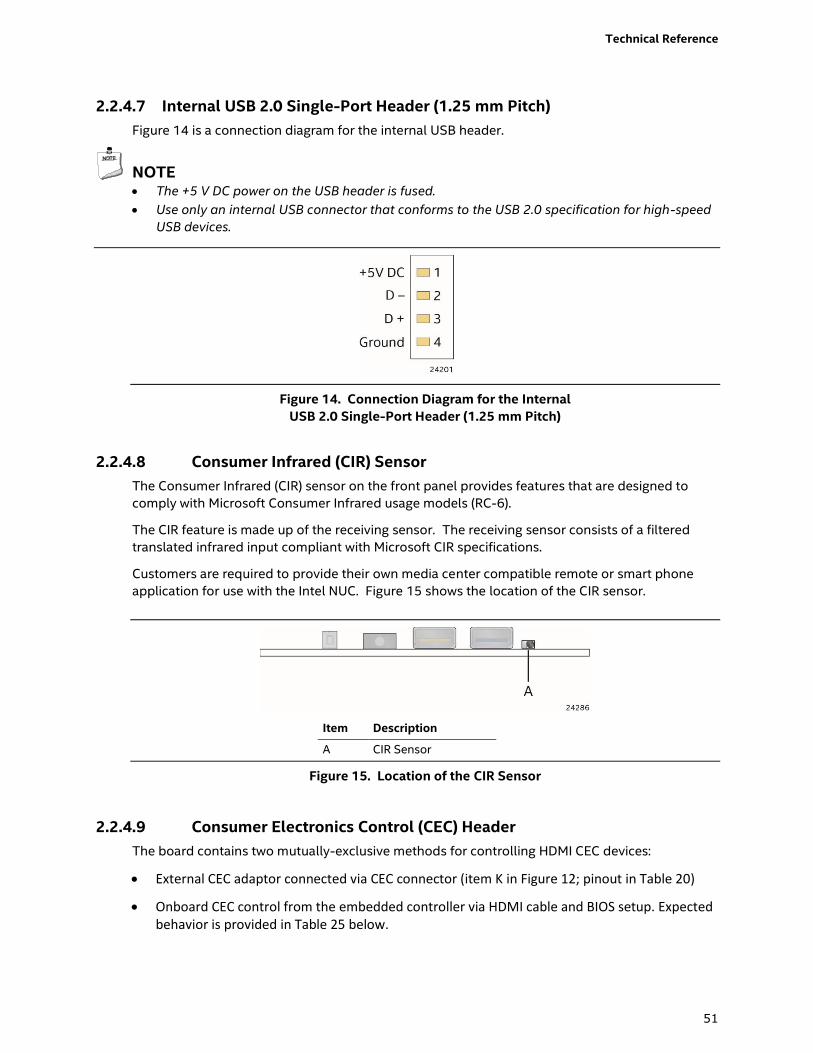
2.2.4.7 Internal USB 2.0 Single-Port Header (1.25 mm Pitch)
Figure 14 is a connection diagram for the internal USB header.
NOTE The +5 V DC power on the USB header is fused.
Use only an internal USB connector that conforms to the USB 2.0 specification for high-speed
USB devices.
Figure 14. Connection Diagram for the Internal
USB 2.0 Single-Port Header (1.25 mm Pitch)
2.2.4.8 Consumer Infrared (CIR) Sensor
The Consumer Infrared (CIR) sensor on the front panel provides features that are designed to
comply with Microsoft Consumer Infrared usage models (RC-6).
The CIR feature is made up of the receiving sensor. The receiving sensor consists of a filtered
translated infrared input compliant with Microsoft CIR specifications.
Customers are required to provide their own media center compatible remote or smart phone
application for use with the Intel NUC. Figure 15 shows the location of the CIR sensor.
Item Description
A CIR Sensor
Figure 15. Location of the CIR Sensor
2.2.4.9 Consumer Electronics Control (CEC) Header
The board contains two mutually-exclusive methods for controlling HDMI CEC devices:
External CEC adaptor connected via CEC connector (item K in Figure 12; pinout in Table 20)
Onboard CEC control from the embedded controller via HDMI cable and BIOS setup. Expected behavior is provided in Table 25 below.
Page 52
52
Table 25. HDMI CEC expected behavior
Activity Current Status Action Expected Behavior
PC1,2 TV3
Wake On TV Off Off TV on PC on
Standby by TV On On TV Standby PC sleep or power off4
Auto Turn Off TV (S0 -> S5) On On PC Shutdown TV standby3
Auto Turn On TV (S5 -> S0) Off Off PC On TV on3
Auto Turn Off TV (S0 -> S3) On On PC Sleep TV standby3
Auto Turn On TV (S3 -> S0) Off Off PC On TV on3
Notes:
1. HDMI CEC Control enabled in BIOS Setup and in TV setup, if necessary. Please consult your TV’s documentation.
2. Fast Boot and Deep S4/S5 disabled in BIOS Setup.
3. Results seen with Panasonic LED TV VIERA TH-40A400W. Other TVs may have different results due to variable implementations of
CEC features.
4. PC power off behavior dependent upon power button setting in operating system.
5. If using external CEC adaptor, onboard CEC control must be disabled in BIOS Setup.
NOTE
CEC Connector is Aces part number 50273-0047C-002, 1.25 mm pitch header, surface mount,
vertical, lead-free, 4 circuits.
2.2.4.10 Front Panel HDD LED Ring
The board supports a front panel HDD LED ring which is connected through Item C shown in
Figure 12. The Front panel HDD LED Ring is configurable within the bios under the Power tab
within Advanced settings. Table 19 lists the signal names of the front panel HDD LED ring
connector.
Table 26. Front Panel LED Ring
Bios Option Possible Configurations
Front Panel HDD LED Ring Color Yellow, cyan, magenta, blue, red, green and white.
Front Panel HDD LED Ring Brightness 0%, 50% 100%
Front Panel HDD LED Ring Activity Indicator None, Power indicator, HDD Activity or Software defined
For information about Refer to
HDMI CEC technology http://www.hdmi.org/pdf/whitepaper/DesigningCECintoYourNextH
DMIProduct.pdf
Page 53
Technical Reference
53
2.2.4.11 Digital Microphone Array
The digital microphone array consists of dual front facing digital microphones located on either
side of the front panel HDD LED ring to minimize acoustic interference. Item L in Figure 12 shows
the location of the digital microphone array connector. Table 18 lists the signal names of the
DMIC connector. See Chapter 5 for the physical location of the DMIC array on the Intel NUC Kit
NUC7i3BN[x] chassis.
2.3 BIOS Security Jumper
CAUTION
Do not move a jumper with the power on. Always turn off the power and unplug the power cord
from the computer before changing a jumper setting. Otherwise, the board could be damaged.
Figure 16 shows the location of the BIOS Security Jumper. The 3-pin jumper determines the
BIOS Security program’s mode.
Table 27 describes the jumper settings for the three modes: normal, lockdown, and
configuration.
Figure 16. Location of the BIOS Security Jumper
Page 54
54
Table 27. BIOS Security Jumper Settings
Function/Mode Jumper Setting Configuration
Normal 1-2 The BIOS uses current configuration information and passwords for
booting.
Lockdown 2-3 The BIOS uses current configuration information and passwords for
booting, except:
• All POST Hotkeys are suppressed (prompts are not displayed and keys
are not accepted. For example, F2 for Setup, F10 for the Boot Menu).
• Power Button Menu is not available (see Section 3.7.4 Power Button
Menu).
BIOS updates are not available except for automatic Recovery due to flash
corruption.
Configuration None BIOS Recovery Update process if a matching *.bio file is found. Recovery
Update can be cancelled by pressing the Esc key.
If the Recovery Update was cancelled or a matching *.bio file was not
found, a Config Menu will be displayed. The Config Menu consists of the
following (selected Power Button Menu options):
[1] Suppress this menu until the BIOS Security Jumper is replaced.
[2] Clear BIOS User and Supervisor Passwords.
See Section 3.7.4 Power Button Menu.
Page 55
Technical Reference
55
2.4 Mechanical Considerations
2.4.1 Form Factor
The board is designed to fit into a custom chassis. Figure 17 illustrates the mechanical form
factor for the board. Dimensions are given in inches [millimeters].
Figure 17. Board Dimensions
Page 56
56
Figure 18 shows the height dimensions of the board.
Figure 18. Board Height Dimensions
2.5 Electrical Considerations
2.5.1 Power Supply Considerations
System power requirements will depend on actual system configurations chosen by the
integrator, as well as end user expansion preferences. It is the system integrator’s responsibility
to ensure an appropriate power budget for the system configuration is properly assessed based
on the system-level components chosen.
2.5.2 Fan Header Current Capability
Table 28 lists the current capability of the fan header.
Table 28. Fan Header Current Capability
Fan Header Maximum Available Current
Processor fan .5 A
Page 57
Technical Reference
57
2.6 Thermal Considerations
CAUTION
A chassis with a maximum internal ambient temperature of 50 oC at the processor fan inlet is
recommended. If the internal ambient temperature exceeds 50 oC, further thermal testing is
required to ensure components do not exceed their maximum case temperature.
CAUTION
Failure to ensure appropriate airflow may result in reduced performance of both the processor
and/or voltage regulator or, in some instances, damage to the board.
All responsibility for determining the adequacy of any thermal or system design remains solely
with the system integrator. Intel makes no warranties or representations that merely following the
instructions presented in this document will result in a system with adequate thermal
performance.
CAUTION
Ensure that the ambient temperature does not exceed the board’s maximum operating
temperature. Failure to do so could cause components to exceed their maximum case
temperature and malfunction. For information about the maximum operating temperature, see
the environmental specifications in Section 2.8.
CAUTION
Ensure that proper airflow is maintained in the processor voltage regulator circuit. Failure to do
so may result in shorter than expected product lifetime.
Page 58
58
Figure 19 shows the locations of the localized high temperature zones.
Item Description
A Processor voltage regulator area
B Thermal solution
Figure 19. Localized High Temperature Zones
Page 59
Technical Reference
59
A thermal pad has been installed for the bottom of the chassis to improve the thermal
performance when using M.2 devices that operate at higher temperatures. If the thermal pad
ever needs to be replaced, Figure 20 shows the installation area of the thermal pad for the Intel
NUC Kit NUC7i3BNK.
Item Description
A Thermal Pad
B Thermal Pad Installation Area
Figure 20. Installation Area of Thermal Pad for Intel NUC Kit NUC7i3BNK
Page 60
60
Figure 21 shows the installation area of the thermal pad for the Intel NUC Kit NUC7i3BNH.
Item Description
A Thermal Pad
B Thermal Pad Installation Area
Figure 21. Installation area of Thermal Pad for Intel NUC Kit NUC7i3BNH
Page 61
Technical Reference
61
Table 29 provides maximum case temperatures for the components that are sensitive to thermal
changes. The operating temperature, current load, or operating frequency could affect case
temperatures. Maximum case temperatures are important when considering proper airflow to
cool the board.
Table 29. Thermal Considerations for Components
Component Maximum Case Temperature
Processor For processor case temperature, see processor datasheets and processor
specification updates
To ensure functionality and reliability, the component is specified for proper operation when
Case Temperature is maintained at or below the maximum temperature listed in Table 30. This is
a requirement for sustained power dissipation equal to Thermal Design Power (TDP is specified
as the maximum sustainable power to be dissipated by the components). When the component is
dissipating less than TDP, the case temperature should be below the Maximum Case
Temperature. The surface temperature at the geometric center of the component corresponds to
Case Temperature.
It is important to note that the temperature measurement in the system BIOS is a value reported
by embedded thermal sensors in the components and does not directly correspond to the
Maximum Case Temperature. The upper operating limit when monitoring this thermal sensor is
Tcontrol.
Table 30. Tcontrol Values for Components
Component Tcontrol
Processor For processor case temperature, see processor datasheets and processor
specification updates
For information about Refer to
Processor datasheets and specification updates Section 1.2, page 20
Page 62
62
2.7 Reliability
The Mean Time Between Failures (MTBF) prediction is calculated using component and
subassembly random failure rates. The calculation is based on the Telcordia SR-332 Issue 2,
Method I, Case 3, 55 ºC ambient. The MTBF prediction is used to estimate repair rates and spare
parts requirements. The MTBF for Intel NUC7i3BNB board is 62,965.
2.8 Environmental
Table 31 lists the environmental specifications for the board.
Table 31. Environmental Specifications
Parameter Specification
Temperature
Non-Operating -40 C to +60 C
Operating 0 C to +35 C
The operating temperature of the board may be determined by measuring the air
temperature from the junction of the heatsink fins and fan, next to the attachment screw,
in a closed chassis, while the system is in operation.
Shock
Unpackaged 50 g trapezoidal waveform
Velocity change of 170 inches/s²
Packaged Half sine 2 millisecond
Product Weight (pounds) Free Fall (inches) Velocity Change (inches/s²)
<20 36 167
21-40 30 152
41-80 24 136
81-100 18 118
Vibration
Unpackaged 5 Hz to 20 Hz: 0.01 g² Hz sloping up to 0.02 g² Hz
20 Hz to 500 Hz: 0.02 g² Hz (flat)
Packaged 5 Hz to 40 Hz: 0.015 g² Hz (flat)
40 Hz to 500 Hz: 0.015 g² Hz sloping down to 0.00015 g² Hz
Note: Before attempting to operate this board, the overall temperature of the board must be above the minimum
operating temperature specified. It is recommended that the board temperature be at least room temperature
before attempting to power on the board. The operating and non-operating environment must avoid condensing
humidity.
Page 63
63
3 Overview of BIOS Features
3.1 Introduction
The board uses Intel Visual BIOS that is stored in the Serial Peripheral Interface Flash Memory
(SPI Flash) and can be updated using a disk-based program. The SPI Flash contains the Visual
BIOS Setup program, POST, the PCI auto-configuration utility, LAN EEPROM information, and
Plug and Play support.
The BIOS displays a message during POST identifying the type of BIOS and a revision code. The
initial production BIOSs are identified as BNKBL357.86A.
The Visual BIOS Setup program can be used to view and change the BIOS settings for the
computer. The BIOS Setup program is accessed by pressing the <F2> key after the Power-On
Self-Test (POST) memory test begins and before the operating system boot begins.
NOTE
The maintenance menu is displayed only when the board is in configure mode. Section 2.3 on
page 53 shows how to put the board in configure mode.
Page 64
64
3.2 BIOS Flash Memory Organization
The Serial Peripheral Interface Flash Memory (SPI Flash) includes a 64 Mb flash memory device.
3.3 System Management BIOS (SMBIOS)
SMBIOS is a Desktop Management Interface (DMI) compliant method for managing computers in
a managed network.
The main component of SMBIOS is the Management Information Format (MIF) database, which
contains information about the computing system and its components. Using SMBIOS, a system
administrator can obtain the system types, capabilities, operational status, and installation dates
for system components. The MIF database defines the data and provides the method for
accessing this information. The BIOS enables applications such as third-party management
software to use SMBIOS. The BIOS stores and reports the following SMBIOS information:
BIOS data, such as the BIOS revision level
Fixed-system data, such as peripherals, serial numbers, and asset tags
Resource data, such as memory size, cache size, and processor speed
Dynamic data, such as event detection and error logging
Non-Plug and Play operating systems require an additional interface for obtaining the SMBIOS
information. The BIOS supports an SMBIOS table interface for such operating systems. Using
this support, an SMBIOS service-level application running on a non-Plug and Play operating
system can obtain the SMBIOS information. Additional board information can be found in the
BIOS under the Additional Information header under the Main BIOS page.
3.4 Legacy USB Support
Legacy USB support enables USB devices to be used even when the operating system’s USB
drivers are not yet available. Legacy USB support is used to access the BIOS Setup program, and
to install an operating system that supports USB. By default, Legacy USB support is set to
Enabled.
Legacy USB support operates as follows:
1. When you apply power to the computer, legacy support is disabled.
2. POST begins.
3. Legacy USB support is enabled by the BIOS allowing you to use a USB keyboard to enter and
configure the BIOS Setup program and the maintenance menu.
4. POST completes.
5. The operating system loads. While the operating system is loading, USB keyboards and mice
are recognized and may be used to configure the operating system. (Keyboards and mice are
not recognized during this period if Legacy USB support was set to Disabled in the BIOS
Setup program.)
6. After the operating system loads the USB drivers, all legacy and non-legacy USB devices are
recognized by the operating system, and Legacy USB support from the BIOS is no longer
used.
Page 65
Overview of BIOS Features
65
To install an operating system that supports USB, verify that Legacy USB support in the BIOS
Setup program is set to Enabled and follow the operating system’s installation instructions.
3.5 BIOS Updates
The BIOS can be updated using one of the following methods:
Intel Express BIOS Update Utility, which enables automated updating while in the Windows
environment. Using this utility, the BIOS can be updated from a file on a hard disk, a USB
drive (a flash drive or a USB hard drive), or a CD-ROM, or from the file location on the Web.
Intel Flash Memory Update Utility, which requires booting from DOS. Using this utility, the
BIOS can be updated from a file on a hard disk, a USB drive (a flash drive or a USB hard drive),
or a CD-ROM.
Intel® F7 switch during POST allows a user to select where the BIOS .bio file is located and
perform the update from that location/device. Similar to performing a BIOS Recovery without
removing the BIOS configuration jumper.
Intel® Visual BIOS has an option to update the BIOS from a valid .bio file located on a hard
disk or USB drive. Enter Intel Visual BIOS by pressing <F2> during POST.
Using Front Panel menu option
Both utilities verify that the updated BIOS matches the target system to prevent accidentally
installing an incompatible BIOS.
NOTE
Review the instructions distributed with the upgrade utility before attempting a BIOS update.
For information about Refer to
BIOS update utilities http://www.intel.com/content/www/us/en/support/boards-and-
kits/000005636.html
3.5.1 Language Support
The BIOS Setup program and help messages are supported in US English. Check the Intel web
site for support.
3.6 BIOS Recovery
It is unlikely that anything will interrupt a BIOS update; however, if an interruption occurs, the
BIOS could be damaged. Table 32 lists the drives and media types that can and cannot be used
for BIOS recovery. The BIOS recovery media does not need to be made bootable.
Table 32. Acceptable Drives/Media Types for BIOS Recovery
Media Type (Note) Can be used for BIOS recovery?
Hard disk drive (connected to SATA or USB) Yes
CD/DVD drive (connected to SATA or USB) Yes
Page 66
66
USB flash drive Yes
USB diskette drive (with a 1.4 MB diskette) No (BIOS update file is bigger than 1.4 MB size limit)
NOTE
Supported file systems for BIOS recovery:
NTFS (sparse, compressed, or encrypted files are not supported)
FAT32
FAT16
FAT12
ISO 9660
For information about Refer to
BIOS recovery http://www.intel.com/content/www/us/en/support/boards-and-
kits/000005532.html
Page 67
Overview of BIOS Features
67
3.7 Boot Options
In the BIOS Setup program, the user can choose to boot from a hard drive, optical drive,
removable drive, or the network. The default setting is for the optical drive to be the first boot
device, the hard drive second, removable drive third, and the network fourth.
NOTE
Optical drives are not supported by the onboard SATA connectors. Optical drives are supported
only via the USB interfaces.
3.7.1 Network Boot
The network can be selected as a boot device. This selection allows booting from the onboard
LAN or a network add-in card with a remote boot ROM installed.
Pressing the <F12> key during POST automatically forces booting from the LAN. To use this key
during POST, the User Access Level in the BIOS Setup program's Security menu must be
set to Full.
3.7.2 Booting Without Attached Devices
For use in embedded applications, the BIOS has been designed so that after passing the POST,
the operating system loader is invoked even if the following devices are not present:
Video adapter
Keyboard
Mouse
3.7.3 Changing the Default Boot Device During POST
Pressing the <F10> key during POST causes a boot device menu to be displayed. This menu
displays the list of available boot devices. Table 33 lists the boot device menu options.
Table 33. Boot Device Menu Options
Boot Device Menu Function Keys Description
<> or <> Selects a default boot device
<Enter> Exits the menu, and boots from the selected device
<Esc> Exits the menu and boots according to the boot priority defined
through BIOS setup
Page 68
68
3.7.4 Power Button Menu
As an alternative to Back-to-BIOS Mode or normal POST Hotkeys, the user can use the power
button to access a menu. The Power Button Menu is accessible via the following sequence:
1. System is in S4/S5 (not G3)
2. User pushes the power button and holds it down for 3 seconds
3. The system will emit three short beeps from the front panel (FP) audio port, then stop to
signal the user to release the power button. The FP power button LED will also change from
Blue to Amber when the user can release the power button.
4. User releases the power button before the 4-second shutdown override
If this boot path is taken, the BIOS will use default settings, ignoring settings in VPD where
possible.
At the point where Setup Entry/Boot would be in the normal boot path, the BIOS will display the
following prompt and wait for a keystroke:
[ESC] Normal Boot
[F2] Intel Visual BIOS
[F3] Disable Fast Boot
[F4] BIOS Recovery
[F7] Update BIOS
[F10] Enter Boot Menu
[F12] Network Boot
[F2] Enter Setup is displayed instead if Visual BIOS is not supported.
[F3] Disable Fast Boot is only displayed if at least one Fast Boot optimization is enabled.
[F9] Remote Assistance is only displayed if Remote Assistance is supported.
If an unrecognized key is hit, then the BIOS will beep and wait for another keystroke. If one of the
listed hotkeys is hit, the BIOS will follow the indicated boot path. Password requirements must
still be honored.
If Disable Fast Boot is selected, the BIOS will disable all Fast Boot optimizations and reset the
system.
Page 69
Overview of BIOS Features
69
3.8 Hard Disk Drive Password Security Feature
The Hard Disk Drive Password Security feature blocks read and write accesses to the hard disk
drive until the correct password is given. Hard Disk Drive Passwords are set in BIOS SETUP and
are prompted for during BIOS POST. For convenient support of S3 resume, the system BIOS will
automatically unlock drives on resume from S3. Valid password characters are A-Z, a-z, and 0-9.
Passwords may be up to 19 characters in length.
The User hard disk drive password, when installed, will be required upon each power-cycle until
the Master Key or User hard disk drive password is submitted.
The Master Key hard disk drive password, when installed, will not lock the drive. The Master Key
hard disk drive password exists as an unlock override in the event that the User hard disk drive
password is forgotten. Only the installation of the User hard disk drive password will cause a hard
disk to be locked upon a system power-cycle.
Table 34 shows the effects of setting the Hard Disk Drive Passwords.
Table 34. Master Key and User Hard Drive Password Functions
Password Set Password During Boot
Neither None
Master only None
User only User only
Master and User Set Master or User
During every POST, if a User hard disk drive password is set, POST execution will pause with the
following prompt to force the user to enter the Master Key or User hard disk drive password:
Enter Hard Disk Drive Password:
Upon successful entry of the Master Key or User hard disk drive password, the system will
continue with normal POST.
If the hard disk drive password is not correctly entered, the system will go back to the above
prompt. The user will have three attempts to correctly enter the hard disk drive password. After
the third unsuccessful hard disk drive password attempt, the system will halt with the message:
Hard Disk Drive Password Entry Error
A manual power cycle will be required to resume system operation.
NOTE
As implemented on Intel NUC Board NUC7i3BNB Hard Disk Drive Password Security is only
supported on either SATA port 0 (M.2 ) or SATA Port 1 (onboard SATA connector). The passwords
are stored on the hard disk drive so if the drive is relocated to another computer that does not
support Hard Disk Drive Password Security feature, the drive will not be accessible.
Currently, there is no industry standard for implementing Hard Disk Drive Password Security on
AHCI or NVME drives. Hard drive encryption can still be implemented and does not require Hard
Disk Drive Password Security.
Page 70
70
3.9 BIOS Security Features
The BIOS includes security features that restrict access to the BIOS Setup program and who can
boot the computer. A supervisor password and a user password can be set for the BIOS Setup
program and for booting the computer, with the following restrictions:
The supervisor password gives unrestricted access to view and change all the Setup options
in the BIOS Setup program. This is the supervisor mode.
The user password gives restricted access to view and change Setup options in the BIOS
Setup program. This is the user mode.
If only the supervisor password is set, pressing the <Enter> key at the password prompt of
the BIOS Setup program allows the user restricted access to Setup.
If both the supervisor and user passwords are set, users can enter either the supervisor
password or the user password to access Setup. Users have access to Setup respective to
which password is entered.
Setting the user password restricts who can boot the computer. The password prompt will be
displayed before the computer is booted. If only the supervisor password is set, the
computer boots without asking for a password. If both passwords are set, the user can enter
either password to boot the computer.
For enhanced security, use different passwords for the supervisor and user passwords.
Valid password characters are A-Z, a-z, and 0-9. Passwords may be up to 20 characters in
length.
To clear a set password, enter a blank password after entering the existing password.
Table 35 shows the effects of setting the supervisor password and user password. This table is
for reference only and is not displayed on the screen.
Table 35. Supervisor and User Password Functions
Password Set
Supervisor
Mode
User Mode
Setup Options
Password to
Enter Setup
Password
During Boot
Neither Can change all
options (Note)
Can change all
options (Note)
None None None
Supervisor only Can change all
options
Can change a
limited number
of options
Supervisor Password Supervisor None
User only N/A Can change all
options
Enter Password
Clear User Password
User User
Supervisor and
user set
Can change all
options
Can change a
limited number
of options
Supervisor Password
Enter Password
Supervisor or
user
Supervisor or
user
Note: If no password is set, any user can change all Setup options.
Page 71
71
4 Error Messages and Blink Codes
4.1 Front-panel Power LED Blink Codes
Whenever a recoverable error occurs during POST, the BIOS causes the board’s front panel
power LED to blink an error message describing the problem (see Table 36).
Table 36. Front-panel Power LED Blink Codes
Type Pattern Note
Power-on Solid on primary color. Indicates S0 state. Default to On; can be disabled
via BIOS Setup
S3 Standby Blink alternate color .25 seconds on, .25 seconds off,
indefinitely. Indicates S3 state.
Default behavior; can be
changed via BIOS Setup
Intel Ready Mode Blink primary color, 1 second on, 1 second off,
indefinitely.
BIOS update in progress Off when the update begins, then primary color on for
0.5 seconds, then off for 0.5 seconds. The pattern
repeats until the BIOS update is complete.
Memory error On-off (1.0 second each) three times, then 2.5-second
pause (off), entire pattern repeats (blinks and pause)
until the system is powered off.
Thermal trip warning Blink primary color .25 seconds on, .25 seconds off, .25
seconds on, .25 seconds off. This will result in a total of
16 blinks (blink for 8 seconds).
4.2 BIOS Error Messages
Table 30 lists the error messages and provides a brief description of each.
Table 30. BIOS Error Messages
Error Message Explanation
CMOS Battery Low The battery may be losing power. Replace the battery soon.
CMOS Checksum Bad The CMOS checksum is incorrect. CMOS memory may have been
corrupted. Run Setup to reset values.
Memory Size Decreased Memory size has decreased since the last boot. If no memory was
removed, then memory may be bad.
No Boot Device Available System did not find a device to boot.
Page 72
72
5 Intel NUC Kit Features
5.1 Chassis Front Panel Features
Intel NUC Board NUC7i3BNB board can be found integrated into Intel® NUC Kit NUC7i3BNH and
Intel® NUC Kit NUC7i3BNK. Figure 22 and Figure 23 shows the location of the features located
on or near the front of the chassis.
Figure 22. Intel NUC Kit NUC7i3BNH Features – Front
Table 37 lists the components identified in Figure 22.
Table 37. Components Shown in Figure 22
Item from Figure 22 Description
Kensington* Anti-Theft Key Lock Hole
Micro SDXC Card Reader
Digital Microphone Array
Power Switch and Power LED
Speaker/Headset Jack
USB 3.0 Connectors
Consumer Infrared Sensor
Page 73
Regulatory Compliance and Battery Disposal Information
73
Figure 23. Intel NUC Kit NUC7i3BNK Features – Front
Table 38 lists the components identified in Figure 23.
Table 38. Components Shown in Figure 23
Item from Figure 23 Description
Micro SDXC Card Reader
Digital Microphone Array
Power Switch and Power LED
Speaker/Headset Jack
USB 3.0 Connectors
Consumer Infrared Sensor
Page 74
74
5.3 Chassis Rear Panel Features
Figure 24 shows the location of the features located on the rear of the chassis.
Figure 24. Intel NUC Kit NUC7i3BNH Features – Rear
Table 39 lists the components identified in Figure 24.
Table 39. Components Shown in Figure 24
Item from Figure 24 Description
19V DC Power Inlet
Cooling Vents
DisplayPort via USB Type-C Connector
USB 3.1 via USB Type-C Connector
USB 3.0 Connectors
Ethernet Port
High Definition Multimedia Interface Connector
Page 75
Regulatory Compliance and Battery Disposal Information
75
Figure 25 shows the location of the features located on the rear of the chassis.
Figure 25. Intel NUC Kit NUC7i3BNK Features – Rear
Table 39 lists the components identified in Figure 25.
Table 40. Components Shown in Figure 25
Item from Figure 25 Description
Kensington* Anti-Theft Key Lock Hole
Cooling Vents
DisplayPort via USB Type-C connector
USB 3.1 via USB Type-C connector
USB 3.0 Connectors
Ethernet Port
High Definition Multimedia Interface Connector
19V DC Power Inlet