Intelligent Inspection System Cell Design Using Computer Vision System to Develop Quality Control System (Case Study: PT. Berlina, Tbk.) Yudha Prasetyawan Department of Industrial Engineering Sepuluh Nopember Institute of Technology, Surabaya 6011, INDONESIA Email: [email protected]Nani Kurniati Department of Industrial Engineering Sepuluh Nopember Institute of Technology, Surabaya 6011, INDONESIA Email: [email protected]Rossy Ariansyah Department of Industrial Engineering Sepuluh Nopember Institute of Technology, Surabaya 6011, INDONESIA Email: [email protected]Abstract. This paper presents an intelligent inspection system (IIS) design based on computer vision system for plastic packaging manufacturer. This intelligent inspection system is engaged to overcome the disadvantages of manual operation such as limited number of inspected products and the limitation of human operator capabilities. With the existing system, it is found that a number of defect products were passed from the inspection process. Computer vision system is engaged to detect and inspect 2D object in this IIS Cell. Then, the captured image is compared with the master image properties to get the similarity percentage of pixel value for individual and moving range (MR) control chart and the value of Cp (process capability). From the identified kind of defects, the root cause analysis (RCA) can be built to justify proper corrective action. As the result, an IIS cell that contains vision system software, SPC and RCA have been made with the right hardware specification. Keywords: quality control, IIS cell, computer vision system, SPC, RCA 1. INTRODUCTION Daily needs products manufacturer have to be very concern with the design and the appearance of products packaging. Even the good packaging will not always guarantee the product quality, but it is a common sense that awful packaging will imply the insufficient quality. Thus, the retail customer will not buy product that has defect packaging, identical to crack, imperfect color, scratched, and other defective type. Therefore, as the packaging supplier PT.BERLINA, Tbk. should be aware to control and maintain their products. At present, some problems emerged in the activities of quality control system in the production line. One of the problems with sampling inspection system for batch of raw material, WIP, and finished good is the high value of probability that the defect products (product which is not suitable with the customer product specification) can be released from the inspection process. Thus, these defect products were found by the customer after product delivery. For this reason, customer will send their claims to PT.BERLINA, Tbk and ask for replacement. The other problem is inspector limitation. Several number of hold label that found in the production line shows that there is no sufficient time for the inspector to do the sampling inspection. If the inspection system relies on the human operator, it will depend on human vision ability to identify the defects. Based on the previous research, defect detection that has been done by human only had 60-70% of accuracy (Huber, et al, 1985). It happens because of fatigue and boredom of inspection operator that emerge during inspection activity with the repetitive and monotone activities. Therefore, the operator ability is not steady during the inspection process activities from the beginning until end of working hour. Those limitations will affect to the number of defect products that were released from inspection process and noted as the good product (products with 1844
Transcript
Intelligent Inspection System Cell Design Using Computer Vision System to Develop Quality Control System (Case
Study: PT. Berlina, Tbk.)
Yudha Prasetyawan
Department of Industrial Engineering Sepuluh Nopember Institute of Technology, Surabaya 6011, INDONESIA
Daily needs products manufacturer have to be very concern with the design and the appearance of products packaging. Even the good packaging will not always guarantee the product quality, but it is a common sense that awful packaging will imply the insufficient quality. Thus, the retail customer will not buy product that has defect packaging, identical to crack, imperfect color, scratched, and other defective type. Therefore, as the packaging supplier PT.BERLINA, Tbk. should be aware to control and maintain their products. At present, some problems emerged in the activities of quality control system in the production line. One of the problems with sampling inspection system for batch of raw material, WIP, and finished good is the high value of probability that the defect products (product which is not suitable with the customer product specification) can be released from the inspection process. Thus, these defect products
were found by the customer after product delivery. For this reason, customer will send their claims to PT.BERLINA, Tbk and ask for replacement. The other problem is inspector limitation. Several number of hold label that found in the production line shows that there is no sufficient time for the inspector to do the sampling inspection. If the inspection system relies on the human operator, it will depend on human vision ability to identify the defects. Based on the previous research, defect detection that has been done by human only had 60-70% of accuracy (Huber, et al, 1985). It happens because of fatigue and boredom of inspection operator that emerge during inspection activity with the repetitive and monotone activities. Therefore, the operator ability is not steady during the inspection process activities from the beginning until end of working hour. Those limitations will affect to the number of defect products that were released from inspection process and noted as the good product (products with
1844
proper specification). Other significant effects are more time needed for inspection process. Therefore it will emerge in delay of delivery time and higher production cost. To overcome all of the limitation of quality control in PT.BERLINA, Tbk., a new system is needed which cover the constraint of manual inspection and sampling system. This system is called intelligent inspection system (IIS) with computer vision system (CVS) method. IIS is an automated inspection system using several types of hardware for product image capturing to identify the image characteristic for inspection purpose using digital image processing. This system is expected to cover human limitation that related to the ability of inspecting all products (online inspection), high complexity, identify the presence of defect, and also plot the similarity percentage into the control chart. Moreover, the system will identify the root cause of defect and determine the proper corrective action in single software. 2. METHODOLOGY
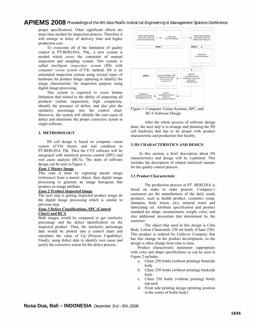
IIS cell design is based on computer vision system (CVS) theory and real condition in PT.BERLINA Tbk. Then the CVS software will be integrated with statistical process control (SPC) and root cause analysis (RCA). The steps of software design can be seen in Figure 1, Zone 1 Master Image
This zone is done by capturing master image (reference) from a master object, then digital image processing to generate an image histogram that produce an image attribute. Zone 2 Product Inspected Image The next step is getting inspected product image do the digital image processing which is similar to previous step. Zone 3 Defect Classifications, SPC (Control
Chart) and RCA
Both images would be compared to get similarity percentage and the defect identification on the inspected product. Then, the similarity percentage data would be plotted into a control chart and calculates the value of Cp (Process Capability). Finally, using defect data to identify root cause and justify the corrective action for the defect process.
IMAGE PROCESSING
(CAPTURE) FOR THE
MASTER PROPERTIES
CREATING
THE HISTOGRAM
IMAGE PROCESSING
(CAPTURE) FOR THE
INSPECTED PRODUCT
CREATING
THE HISTOGRAM
DEFECT
CLASSIFICATION
BASED ON THE PIXEL
SIMILARITY
PERCENTAGE
DATA GATHERING FOR
CREATING SPC AND
CALCULATE THE
VALUE OF CP
DEFECT
CLASSIFICATION TO
FIND OUT
THE CAUSE OF DEFECT
GENERATE
CORRECTIVE ACTION
RECOMMENDATION
ZONE 1
ZONE 3
ZONE 2
Figure 1: Computer Vision Systems, SPC, and
RCA Software Design
After the whole process of software design done, the next step is to arrange and planning the IIS cell hardware that has to be proper with product characteristic and production line facility. 3. IIS CHARACTERISTICS AND DESIGN
In this section, a brief description about IIS characteristics and design will be explained. This includes the description of related statistical manner for the quality control process.
3.1 Product Characteristic
The production process in PT. BERLINA is
based on make to order process. Company’s customers are the manufacturer of the daily needs products, such as health product, cosmetics (soap, shampoo, body lotion, etc), mineral water and lubricating oil. Attribute specification and product standard are shape, measurement, weight, color, and also additional decoration that determined by the customer.
The object that used in this design is Citra Body Lotion Chamomile 250 ml bottle (Cham 250). This product is ordered by Unilever Company that has fast change in the product development, so the design is often change from time to time.
Product characteristic parameter (appropriate with color and shape specification) as can be seen in Figure 2 includes:
a. Cham 250 bottle (without printing) frontside body
b. Cham 250 bottle (without printing) backside body
c. Cham 250 bottle (without printing) bottle top neck
d. Front side printing design (printing position in the centre of bottle body)
APIEMS 2008 Proceedings of the 9th Asia Pasific Industrial Engineering & Management Systems Conference
December 3rd – 5th, 2008 Nusa Dua, Bali – INDONESIA 1845
3BGR ++
e. Backside printing design (printing position in the centre of bottle body)
(a) (b) (c)
(d) (e)
Figure 2: Cham 250 Bottles (Blow Molding and Printing Products) At the production line of Cham 250, many kinds of defect type are often found in blow molding (bottle making) and decoration (printing) division. Defect classification is also conducted by pointing the defect location, which is including part of neck and body bottle. Defect classification in this research is described in Table 1. Table 1: Defect Classification Cham 250
(Information from the company)
Blow Molding Decoration (Printing) Index
Neck Body BM Body Printing
1 Bubbles form
Collapsed Body Inversed printing
2 Broken top side
Burnt Material Unclear text
3 Oval top side Impurities Broken text
4 Crack on the edges Hole/crack Unmatched color
5 Hole/crack Improper text printing
6 Text with several dots
7 Lost part of printing
3.2. Software CVS Design Integrated with SPC
and RCA
This section describes programming
algorithm, programming rules (including image processing module using tool named image histogram, individual and MR chart design, database
root cause analysis and corrective action design. The software would be named as IISC 1.0
3.2.1 Defect Identification Mechanism
In general, defect identification mechanism is done by comparing two attributes of two digital image of cham 250 (master and product inspected image) and then calculating the similariy percentage between those two attributes. If the value of similarity percentage is a hundred percent, it can be moted that image of inspected product suitable with master image.
Detail step of product defect identification is described below, 1. Image Gray scaling Step
For every pixel value, taje Red, Green, and Blue (RGB) feature, then calculate the average of those value until getting the value of grey level, which is Graylevel Value = (1)
Figure 3: Image Grayscaling Step
2. Histogram Generating Step
Array inisialisation in one dimension with capacity, means that the array would have index starting from 0 until 255 for collecting the value of pixel for every graylevel feature starting from 0 until 255. In image, iteration is done by starting from the first until the last sequence. Array is added with one (1) with index is the value of pixel. For an example, pixel value = 115, so array with index 115 is added with one so the value now is 116.
Figure 4: Histogram Generating
3. Euclidean distance (S) Calculation
After getting two attributes of master and inspected product image, the next step is to
APIEMS 2008 Proceedings of the 9th Asia Pasific Industrial Engineering & Management Systems Conference
December 3rd – 5th, 2008 Nusa Dua, Bali – INDONESIA 1846
continue with calculating euclidean distance (S), with the formula below, (2)
This calculation would be done, starting from array with 0 index until 255 in both of histograms. Euclidean distance would be assigned as value of difference rate variable.
4. Similarity Value of Pixel Calculation
Similarity value of pixel between both histograms for every graylevel array index is the minimum value between two values at the same index. For example, the 1st index value for master image istogram equal with 11 pixel and the 1st index value for inspected product image is 90, so similarity value of pixel equal with min(11,90)=11 pixel. Then, number would be multiplied with 2, and fill the number to the collecting variable and would be squared root. The formula of similarity value of pixel is,
; (n=256) (3)
5. Similarity Percentage Calculation
Formula of similarity percentage calculation is written below, % similarity =
(4)
After similarity percentage from two images is calculated as the formulas above, the next step is to determine the value for defect classification using trial and error method. From the trial, it could be derived the value of similarity percentage and this value would be used as specification defect limit value for the inspected image product.
Figure 5: Defect Product Identifying Step
3.2.2 Control Chart Individual and MR Design
After getting the value of similarity percentage
for every inspected product image from each station (blow molding and printing), the next step is plotting the whole similarity percentage value to the individual and moving range (MR) control chart.
MR= │Xi – Xi-1 │ (5)
In the same time also can be done the calculation of process capability (Cp) which the parameters have been dtermined before (by input USL and LSL value) and also other parameter is gotten from MR average
calculation ( MR ). Individual and MR control chart plotting were based on the calculation of upper and lower control limit also centre line which is based on the value of moving range average, as the MR chart formulas below,
UCL (Upper Control Limit) = MRD .3 (6)
CL (Centre Line) = MR (7)
LCL (Lower Control Limit) = MRD .4 (8)
Where MR = value of average moving range from the whole inspected product. D3 and D4 are the constant value from an approach factors of 3σ from the average value of MR. D3 and D4 constanta can be seen at factors for constructing variables control chart table. Another type of control chart that can be built is individual observation control with the parameter and formulas described below,
UCL (Upper Control Limit) = 2
3d
MRX + (9)
CL (Centre Line) = X (10)
LCL (Lower Control Limit) = 2
3d
MRX − (11)
Where X is the average value from whole observation, and d2 is factors for constructing variables control chart depends on number of its subgroup (n). 3.2.3 Root Cause Analysis (RCA) Design
The aim of RCA design is to find out the root cause of defect emerging on product from the output of blow molding and printing machine. For every defect type that emerge from each station, it would be tracked until it can identified the root cause by questioning why a condition can happen.
RCA design is based on data from direct observation and interview with foreman of each division including quality control division. RCA data can be updated everytime because it is design using a database. RCA calling rules is using query rules in database. Table 2: RCA Chart Example for Material Burnt
Defect
Variable Why 1 Why 2 Why 3 Why 4 Blow
Molding Product Defect
Burnt Material
Inversed printing
Bottle Tonsil
Collapsed Body
[ ])2).((...)2).,(()2).,(( 2122122111 nn yyMinyyMinyyMin −+++
APIEMS 2008 Proceedings of the 9th Asia Pasific Industrial Engineering & Management Systems Conference
December 3rd – 5th, 2008 Nusa Dua, Bali – INDONESIA 1847
3.2.4 Corrective Action Identification
Corrective action is designed based on the root cause of defect in every station. This corrective action is expected to minimize the time for determining repairment of machining and production system. Corrective action is identified based on machining process mechanism, material flow and warehousing. Moreover a preventive action to minimize the number of defect is also justified.
The rules of corrective action in this software is using if-then concept. For example, if, root cause = inappropriate connection kern duse, then, corrective action = uncover die head, clean the contamination in kern duse
Table 3 : Corrective Action of Process
3.2.5 IISC 1.0 Software Application Test
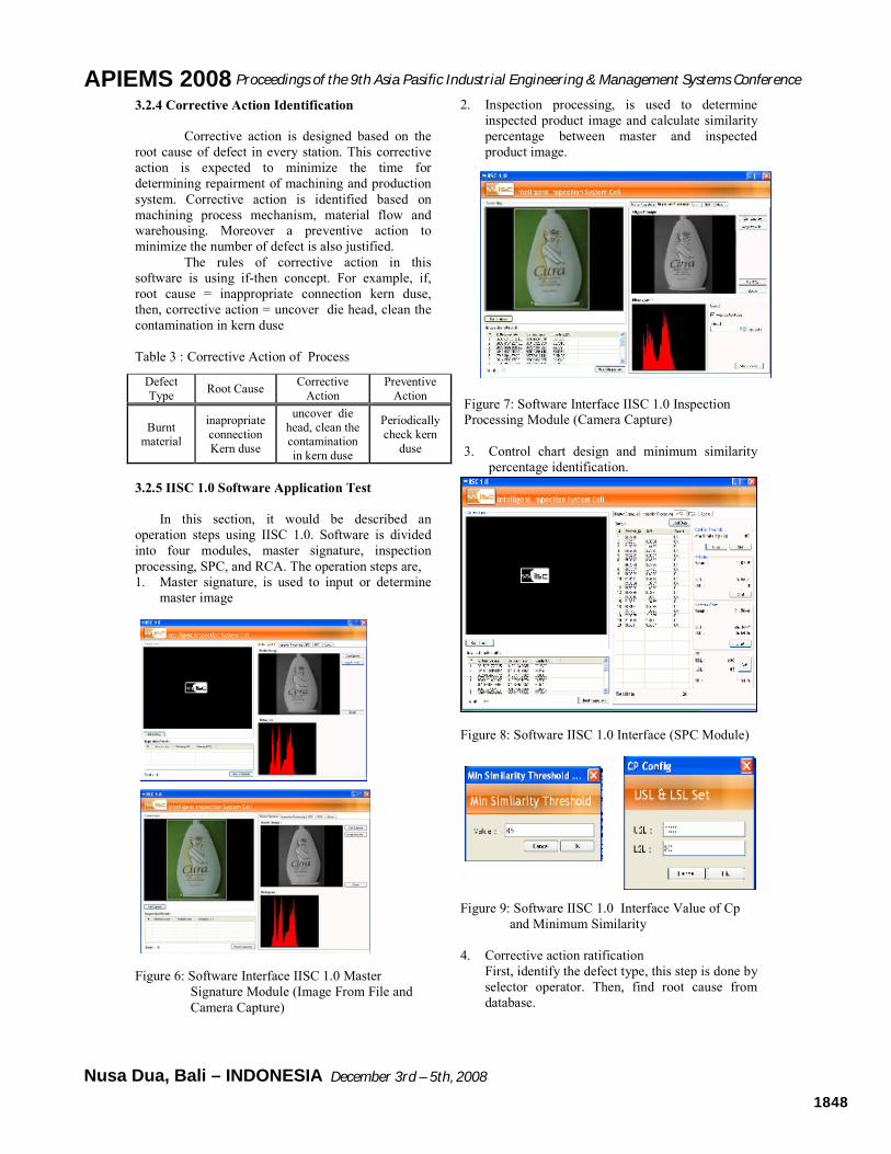
In this section, it would be described an operation steps using IISC 1.0. Software is divided into four modules, master signature, inspection processing, SPC, and RCA. The operation steps are, 1. Master signature, is used to input or determine
master image
Figure 6: Software Interface IISC 1.0 Master
Signature Module (Image From File and Camera Capture)
2. Inspection processing, is used to determine inspected product image and calculate similarity percentage between master and inspected product image.
Figure 7: Software Interface IISC 1.0 Inspection Processing Module (Camera Capture) 3. Control chart design and minimum similarity
4. Corrective action ratification First, identify the defect type, this step is done by selector operator. Then, find root cause from database.
Defect Type Root Cause Corrective
Action Preventive
Action
Burnt material
inapropriate connection Kern duse
uncover die head, clean the contamination in kern duse
Periodically check kern
duse
APIEMS 2008 Proceedings of the 9th Asia Pasific Industrial Engineering & Management Systems Conference
December 3rd – 5th, 2008 Nusa Dua, Bali – INDONESIA 1848
Figure 10: RCA Dialog (Defect Type Determining
Step 1)
Figure 11: RCA Dialog (Defect Type Determining
Step 2)
Figure 3.11 RCA Module (Corrective Action) Figure 12: RCA and Corrective Action Result 3.2.6 First Read Rate Test (FRR)
First read rate test at IISC 1.0 software is utilized to see the software reliability in determining the equality percentage between the master product image and the observed object. In other words, this test is used to see the software ability in classifying good or defect product according to the actual condition of the product.
First rate read test at IISC 1.0 could be conducted in two ways:
1. Conducting the test by inserting the same image as the the master product image and the observation product. The expected ideal result is to acquire the percentage of equality equal to 100%. This test is conducted 10 times successively with different image, and the results are follows,
The result of the first FRR test can be taken as a conclusion that from 10 product images which is observed, IISC 1.0 software capable to identify the overall product truly equal to 100%. Table 4: FRR (1 and 2) Test Result
two images differ from first image as master product image and second image as observation product image. The ideal result expected from this test is in the value of percentage of equality less than 100%. From the results of second FRR, it can be concluded that from 10 images which is observed IISC software 1.0 is capable to identify the overall product truly equal to 100%.
3.3 Compilation and Scheme of Hardware
The selection of hardware components required
at the IIS cell is conducted only for the purpose of inspection process – disregard the blow molding and printing machines. The components are: 1. Conveyor, is able to transport the material
continuously (the flow rate of raw material into the machine similar to the flow of the finished goods out of the machine).
2. Object orientor, is utilized to move the product into the desired orientation or position while on the conveyor.
3. Ultrasonic censor, in IIS cell this device is used to detect the product arrival at the inspection station.
4. Clamp, is used to hold the product which then to be captured by the camera - so the product is in motion less position and on the proper orientation.
5. High speed camera, the IIS cell use the digital image bases which is acquired from the result output from the high speed camera.
APIEMS 2008 Proceedings of the 9th Asia Pasific Industrial Engineering & Management Systems Conference
December 3rd – 5th, 2008 Nusa Dua, Bali – INDONESIA 1849
6. Microcontroller, is employed as a control and to deliver/generate order from the conveyor, censor, clamp, and the rejector lever.
7. Computer (PC), is used as system main control device for the entire cell activities.
8. Rejector valve is utilized as the device which classifies the group of the good and defect product. Rejector valve will push the defect product out of the conveyor when the microcontroller generates command to the rejector for doing so.
The main purpose of this election process is to acquire the conveyor with the minimum cost but have optimum performance. The value of each component has been determined based on the technical parameter (it is assumed that the feature with high resolution is equal to a high price, vice versa). The technical parameter value at each feature has been converted in 1 to 5 range of value with the information, number 5 representing the cheapest price and number 1 representing the highest price. 3.3.1 Automation Algorithm
The set of rules that is made for automation algorithm at the blow molding and printing station are follows: 1. The conveyor will keep running (transferring the
cham 250 bottle which is exiting the blow molding machine into the inspection station continously).
2. The censor 1 detects the presence of a product, censor 1 output = 1; censor 2 output = 0, the output will be delivered to the microcontroller. Conveyor still running.
3. Censor 1 and 2 detects the presence of a product, censor 1 output = 1; censor 2 = 1, the output is delivered to the microcontroller. Conveyor stop.
4. Delay constant time one second • Clamp hold the product • Microcontroller transferring data as a serial
that the product is ready to be captured. • Camera 1 captured the body part of the
bottle; camera 2 captured the mouth part of the bottle.
5. After one second, the conveyor will running again (software processing the entry data)
6. After ± one second, the software which is accomodates the entry from both cameras will transfer the data output to the microcontroller.
7. Back to step 1
Figure 13: IIS Cell Automation Algorithm
3.3.2 IIS Validation Test
The test through a simulation model is conducted
at the IIS cell blow molding and decoration (printing) division. The purpose of this validation test is to analyze whether the designed model of IIS cell can be applied on the real condition of the production floor with the standard deviation parameter of the production output or not based on the number of output.
After the ISS cell arena model and the real system is simulated, the output of both model will be compared with the Welch confidence interval method. It can be concluded that the initial arena model is significantly different, so the IIS cell model can be applied with the insignificant different output value.
APIEMS 2008 Proceedings of the 9th Asia Pasific Industrial Engineering & Management Systems Conference
December 3rd – 5th, 2008 Nusa Dua, Bali – INDONESIA 1850
Table 5: Output Number of Printing machines (Existing, Arena, and IIS cell Arena)
Day Printing Machine Output
Arena Output
Arena IIS Cell
Output
1 74900 71445 82472
2 72450 71504 82472
3 67200 71527 82472
4 67200 71539 82471
5 75600 71478 82472
6 79800 71528 82472
7 72400 71550 82472
8 71800 71491 82472
9 67400
10 68350
stdev 4247.012
Var 18037111 1237.071 0.125
mean 71710 71507.75 82471.88
Arena Simulation Model Validation (Printing
System)
The Equation of the Arena Simulation Replication (Printing System) n = 10 α = 0.05 s = 4727.012 (12) (13) From the replication number equation above, when arena simulation is conducted eight times replication for each system. After the simulation, the output is acquired from the number of the bottle which is exiting the printing system. Hypothesis: H0: µ1 - µ2 = 0 H0:µ1 - µ2 ≠ 0; (14) (15)
(16) Conclusion: Accept H0, which means that the arena initial model and IIS cell are significantly indifferent.
Then, the validation phases between IIS cell arena model and the initial model is used with the same phases similar to the previous process. Conclusion: Reject H0 which mean that the initial arena model with the IIS cell arena model is significantly different. 4. DESIGN ANALYSIS
In this section, it would be described about overall design analysis, ability of software IISC 1.0, and analysis of IIS cell design validation 4.1 CVS Software, SPC and RCA (IISC 1.0)
Design Analysis
The IISC 1.0 software is a prototype for completing the IIS cell. The software will overcome the problem that arises from conducting inspection process with sampling method at present. At the IISC 1.0 software, there are 4 main modules which each module is designed to be able for accommodating its own function. The first module has function to acquire the attribute (image histogram) from one master product image. The next module is the inspection process for inspecting the observed object. This includes capturing process of the observed object, the equation of the equality percentage and also the entry of the root cause from the defect type. The third model has function for creating the MR control map and the individual data which is acquired from the second module. The function of the last module is RCA to determine the proper repair action. This recommendation is ratified from the root cause that was inserted at the second module.
In the IISC 1.0 software, it also has been created an auto process mode so that the inspection process (product capturing process until the equality
APIEMS 2008 Proceedings of the 9th Asia Pasific Industrial Engineering & Management Systems Conference
December 3rd – 5th, 2008 Nusa Dua, Bali – INDONESIA 1851
percentage is acquired) can be arranged automatically only by inserting the product capturing time interval for the camera. For example, if the time interval setting which is set to one second then the software will generate an order to the camera for capturing the product with one second time interval every image capturing. With the existence of the automatic model, the inspector or selection operator will only need to supervise the inspection process and have more time for production process improvement.
The time needed for IISC 1.0 software to acquire the equality percentage value is estimated less than one second, and the process is running constantly. The constant one second processing time is better than the manual inspection time which needs time with the normal distribution (1, 0.12). However, it is possible to the production output result to be acquired and with the more constant time. Thus, the inspection process can be relying on this software. 4.2. Software First Read Rate Analysis
As can be seen in section 3.2, this software has passed the requirement of its reliability based on this analysis. From both test, it can be concluded that the IISC 1.0 software is able to identify the entire entry image with no mistakes (0% error) if the operation standard is like the requirement in the proposed IIS cell. This conclusion can be derived from the process of acquiring the equality percentage value based on the Euclidean range and similarity pixel value. If there are two same images exist, the constructed image histogram was also similar for all of its compiler attributes, and vice versa.
The attributes for constructing the histogram were from the pixel value (0-255) and the intensity of each pixel will be used to search the equality percentage value. If all the attributes have the same values, the equality percentage value will equal to 100%. On the contrary, if there is difference between both of histogram then the equality percentage value would less than 100% value. 4.3. IIS cell Design Validation Analysis
The IIS cell design analysis has been
conducted by comparing the production output acquired by each division at the existing condition, with the division that is integrated by the IIS cell. Simulation tool with the ARENA 5.0 software was used. The initial phase of the validation is used for comparing the existing system with the arena model. The result is accept Ho which means that the arena model simulated can be stated as equal to the real condition, so the next phase comparing the IIS cell arena model can be executed. The result acquired from the statistic test of the comparison with the Welch comparison method is reject Ho. It means that IIS cell arena model and the real system are significantly different.
The number of output can be stated constant, based on the minimum value of standard deviation at the IIS cell. Then then number bottle output that exit from the system has small standard deviation. So, it can be stated that the output is tend to be constant. 5. CONCLUSION
Some of the conclusion that may be taken
from this research is as following: 1. The defect type at the Cham 250 product is
classified into two groups, blow molding and decoration-printing.
2. With the IISC 1.0 software the product inspection process can be conducted online with the constant inspection process time (one second) it can decrease the defect product possibility for the customer.
3. IISC software 1.0 have the IISC 1.0 software Own excess in the form of direct repair action data can be seen instantly by selector operator and can be update so that it can cut the time to identify repair action and shortened time of repair process.
4. IIS cell is compiled with the hardware component as conveyor, object orientor, ultrasonic censor, clamp, high speed camera, microcontroller, computer (PC), Rejector valve (cylinder switch).
5. The IIS cell validation test concludes that the standard deviation value acquired is smaller which means that the result of production output amount tend to be more stable, all of the product can be inspected directly and in the short amount of time. Also generate the production output amount that is fit to the target determined by the company.
6. REFERENCES
Aqmar,M.R ,K. Deddy, Y.Sonny.(2005).
Pengembangan Perangkat Lunak Komputasi untuk Pemantauan Kinerja Plant Secara Real Time dengan Metoda Statistical Process Control, Departemen Teknik Fisika , Institut Teknologi Bandung
Eidarous, Al Mustafa. (1998). Locating Defects on Shirt Collars Using Image Processing, Department
of Electronic Engineering, University of Hull, UK Gonzales,Rafael,C. dan Woods, Richard,E.
(2002). Digital Image Processing. Prentice Hall, New Jersey.
Groover, P.Mikell. (2001). Automation, Production Systems and Computer Integrated Manufacturing. Prentice Hall, New Jersey
H.A.Huber, C.W. McMillin, J.P McKinney (1985). Lumber Defect Detection Abilities of Furniture Rough Mill Employees. Forest Production Journal, 35(11/12).
APIEMS 2008 Proceedings of the 9th Asia Pasific Industrial Engineering & Management Systems Conference
December 3rd – 5th, 2008 Nusa Dua, Bali – INDONESIA 1852
System, Industrial Research Institute Swinburne, Victoria.
Keyvan, Shahla (1999). Final Report DOE Project DE-FG07-98ID13644, University of Missouri, Rolla.
Kristanto, Triono (2002). Validasi Uang Kertas Rupiah dengan Teknologi Image Processing. Tugas Akhir Teknik Elektro UK Petra, Surabaya.
Montgomery, Douglas, C. (1985). Introduction to Statistical Quality Control. John Willey & Sons, Washington DC.
Prabuwono, A.S, R. Sulaiman, A.R. Hamdan, A.Hasniaty. (2006). Development of Intellegent
Visual Inspection System (IVIS) for Bottling Machine, Fac of inf. Technology, Budi Luhur University
Wilcox, Mark. (2002). Statistical Process Control Applied to Automatic Ultrasonic Inspection. Paper of Insight NDT Equipment Ltd.
AUTHOR BIOGRAPHIES
Yudha Prasetyawan is a Lecturer in Department of Industrial Engineering, Faculty of Industrial Technology, Sepuluh Nopember Institute of Technology, Indonesia. He received a Master Degree for Advanced Manufacturing Technology from the Graduate Swinburne University of Technology, Australia in 2005. His teaching and research interests include manufacturing system and computer integrated manufacturing (CIM). His email address is <[email protected]>
Nani Kurniati is a Lecturer in Department of Industrial Engineering, Faculty of Industrial Technology, Sepuluh Nopember Institute of Technology, Indonesia. She received a Master Degree from Bandung Institute of Technology. Her teaching and research interests include manufacturing system, quality control, and statistic. Her email address is <[email protected]>
Rossy Ariansyah is a student in Department of Industrial Engineering, Faculty of Industrial Technology, Sepuluh Nopember Institute of Technology, Indonesia. Her research interest include manufacturing system and supply chain management. Her email address is <[email protected]>
APIEMS 2008 Proceedings of the 9th Asia Pasific Industrial Engineering & Management Systems Conference
December 3rd – 5th, 2008 Nusa Dua, Bali – INDONESIA 1853