Page 1
Intelligent License Plate Positioning Identification
System Based on FPGA Hu-Cheng Xie1, Mi Zhou2, and Pei Zhang3
College of Educational Information and Technology, Hubei Normal University
Huangshi, China
[email protected] [email protected]
[email protected]
Abstract— With the rapid development of China's national
economy, intelligent transportation systems has become the main
direction of the development of traffic management, and license
plate recognition system technology as the core of intelligent
transportation system plays a pivotal role. This paper describes a
theory based on Altera's CYCLONE II EP2C35 devices on the
platform location and license plate recognition system. The
system mainly works like this: First, camera module reads a
license plate image, then through the image plate rough
positioning, image graying, median filter, sobel operator edge
detection, image binarization, plate processing such as automatic
positioning precision positioning plate, and also through the
establishment of NIOS II soft-core processor for the license plate
character segmentation, and then match a single character
segmentation, license plate recognition. In this system, some of
the basic positioning using Verilog hardware description
language, implemented in hardware for parallel processing large
amounts of data, processing speed, high accuracy. For image
positioning plate, color image based positioning methods; the
algorithm is simple, less memory, which makes it possible to
achieve fast and accurate positioning plate. License plate
segmentation algorithm uses the traditional template matching
algorithm. By establishing SOPC system allows users more easily
to interact through the software license plate recognition,
thereby provides greater flexibility.
Keywords— license plate positioning; FPGA; the image
processing; Character segmentation
I. INTRODUCTION
With the development of the traffic, the intelligent
transportation system (ITS) has attracted more attention in
traffic management, and in ITS, License plate recognition
(LPR) is the core technology. The LPR system is mainly
composed of date acquisition system and software recognition
system. Some factors, such as the degree of clarity of the
license plate, the Camera performance, and climate conditions,
which have effects on license plate recognition .characters in
the license plate, may become unclear, warping and defective.
Thus, it is the key for license plate recognition system to get
the license plate position quickly and accurately in complex
surroundings. And the camera performance is also the
important precursor condition, so it is better to chose one with
high performance. IPL is to recognize license plate
automatically by processing, positioning, analysing, and
taking in the car images.
LPR has been used widely, and it is mainly used in:
(1) Highway monitoring management system.
(2) Neighbourhood pacing management
(3) Monitoring the driver in the city to see if any violation of
the management
(4) License plate login authenticating
(5) The traffic statistics, the safety management.
LPR system is applied to those aspects, to solve the
violation of the management of cars, check it automatically, to
solve the traffic problem that is caused by the peak of the
traffic flow, to realize the traffic department of vehicle
information connected to the Internet. It is also used to realize
the statistics of traffic automatically and the fuzzy inquiring.
Thus, the LPR system will be used widely, and the characters
recognition in license plate is one of the key technologies of
intelligent computer. It involves in mode recognition,
characters recognition, labour intelligent, the information
theory, computers and many other subjects. It is a
comprehensive technology, and it has a widely range of
practical applications.
Along with the development of high and new technology,
such as image processing and computer vision, the sensor,
communication and network technology, LPR also got great
progress, and it plays an important role in management level
and automation degree of the traffic system. Now there are a
variety of technical means that can be used for license plate
recognition system, such as using single-chip microcomputer
to realize the control of the whole system and invoked, but in
the process of application, because the license plate
recognition needs to process a large number of data, which
requires the chip system to possess a large processing power.
Since it will have the function of real-time monitoring, then
the system needs to have certain intelligence and so on. All
kinds of single chip microcomputer in general situations can
also be applied, but in such places, like the traffic intersection
or gate, single-chip microcomputer for data processing
capacity is not enough. The volume of the whole system is
too large, the cost is very high, and common maintenance is
inconvenient, but with the emergence of complex
Page 2
2
programmable logic device (CPLD), the above questions are
answered. But there is still a problem which associated with
peripheral module's high price, and thus limits its
development, for example, a CPLD chip and used in image
processing and digital signal processing (DSP) chip. The
related peripheral circuit and computer, etc, the overall price
is still high, thus limiting the further development of license
plate recognition system [3]. In recent years, with the
emergence of the field programmable gate array (FPGA), the
problem has been resolved, but the integration is not enough.
After in a few years since FPGA's appearance, we now have
the SOPC system based on FPGA platform, the function of
the platform is used to coordinate and call on FPGA logic
gates and other devices, and on this basis developed the NIOS
II, now have some multiplier in FPGA, so that you can use
Quartus II to communicate with the FPGA directly to
complete the software of digital signal processing, greatly
reduce cost this problem solved, and good portability, easy
maintenance, etc [7-9].
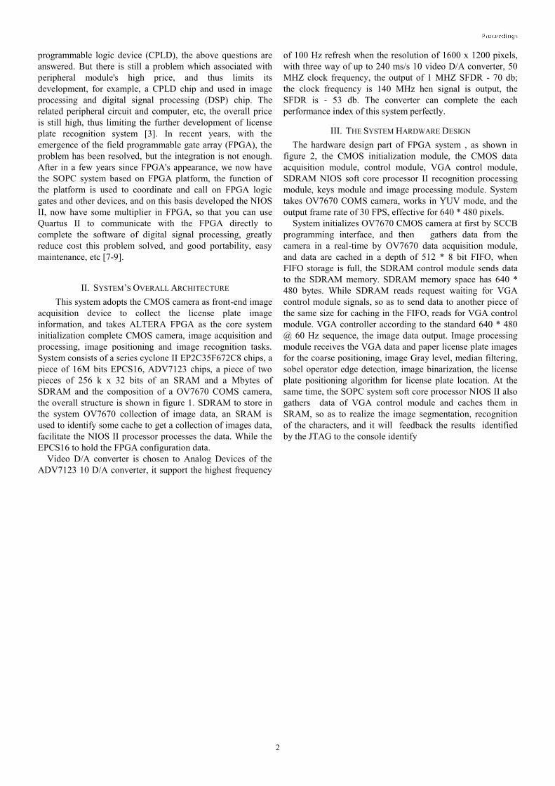
II. SYSTEM’S OVERALL ARCHITECTURE
This system adopts the CMOS camera as front-end image
acquisition device to collect the license plate image
information, and takes ALTERA FPGA as the core system
initialization complete CMOS camera, image acquisition and
processing, image positioning and image recognition tasks.
System consists of a series cyclone II EP2C35F672C8 chips, a
piece of 16M bits EPCS16, ADV7123 chips, a piece of two
pieces of 256 k x 32 bits of an SRAM and a Mbytes of
SDRAM and the composition of a OV7670 COMS camera,
the overall structure is shown in figure 1. SDRAM to store in
the system OV7670 collection of image data, an SRAM is
used to identify some cache to get a collection of images data,
facilitate the NIOS II processor processes the data. While the
EPCS16 to hold the FPGA configuration data.
Video D/A converter is chosen to Analog Devices of the
ADV7123 10 D/A converter, it support the highest frequency
of 100 Hz refresh when the resolution of 1600 x 1200 pixels,
with three way of up to 240 ms/s 10 video D/A converter, 50
MHZ clock frequency, the output of 1 MHZ SFDR - 70 db;
the clock frequency is 140 MHz hen signal is output, the
SFDR is - 53 db. The converter can complete the each
performance index of this system perfectly.
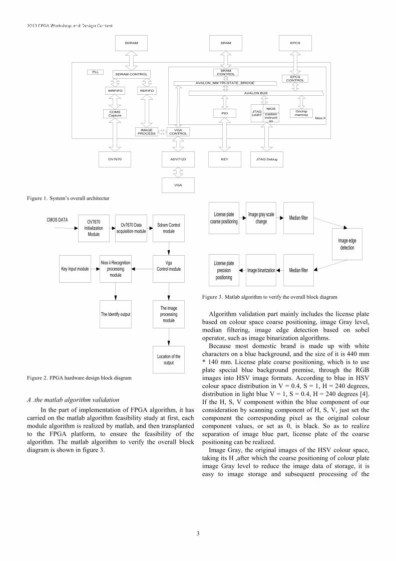
III. THE SYSTEM HARDWARE DESIGN
The hardware design part of FPGA system , as shown in
figure 2, the CMOS initialization module, the CMOS data
acquisition module, control module, VGA control module,
SDRAM NIOS soft core processor II recognition processing
module, keys module and image processing module. System
takes OV7670 COMS camera, works in YUV mode, and the
output frame rate of 30 FPS, effective for 640 * 480 pixels.
System initializes OV7670 CMOS camera at first by SCCB
programming interface, and then gathers data from the
camera in a real-time by OV7670 data acquisition module,
and data are cached in a depth of 512 * 8 bit FIFO, when
FIFO storage is full, the SDRAM control module sends data
to the SDRAM memory. SDRAM memory space has 640 *
480 bytes. While SDRAM reads request waiting for VGA
control module signals, so as to send data to another piece of
the same size for caching in the FIFO, reads for VGA control
module. VGA controller according to the standard 640 * 480
@ 60 Hz sequence, the image data output. Image processing
module receives the VGA data and paper license plate images
for the coarse positioning, image Gray level, median filtering,
sobel operator edge detection, image binarization, the license
plate positioning algorithm for license plate location. At the
same time, the SOPC system soft core processor NIOS II also
gathers data of VGA control module and caches them in
SRAM, so as to realize the image segmentation, recognition
of the characters, and it will feedback the results identified
by the JTAG to the console identify
Page 3
3
OV7670
SDRAM
ADV7123
VGA
Nios II
SRAM
KEY
WRFIFO RDFIFOAVALON BUS
SRAM
CONTROLEPCS
CONTROL
EPCS
SDRAM CONTROLPLL
IMAGE
PROCESS
COMS
Capture
VGA
CONTROL
PIOOnchip
memray
JTAG Debug
JTAG
UART
NIOS
custom
instructi
on
AVALON_MM TRI-STATE_BRIDGE
Figure 1. System’s overall architectur
OV7670
Initialization
Module
Ov7670 Data
acquisition module
Sdram Control
module
Vga
Control module
The image
processing
module
Location of the
output
Nios ii Recognition
processing
module
The Identify output
Key Input module
CMOS DATA
Figure 2. FPGA hardware design block diagram
A .the matlab algorithm validation
In the part of implementation of FPGA algorithm, it has
carried on the matlab algorithm feasibility study at first, each
module algorithm is realized by matlab, and then transplanted
to the FPGA platform, to ensure the feasibility of the
algorithm. The matlab algorithm to verify the overall block
diagram is shown in figure 3.
License plate
coarse positioning
Image edge
detection
Median filterImage gray scale
change
Median filterImage binarization
License plate
precision
positioning
Figure 3. Matlab algorithm to verify the overall block diagram
Algorithm validation part mainly includes the license plate
based on colour space coarse positioning, image Gray level,
median filtering, image edge detection based on sobel
operator, such as image binarization algorithms.
Because most domestic brand is made up with white
characters on a blue background, and the size of it is 440 mm
* 140 mm. License plate coarse positioning, which is to use
plate special blue background premise, through the RGB
images into HSV image formats. According to blue in HSV
colour space distribution in V = 0.4, S = 1, H = 240 degrees,
distribution in light blue V = 1, S = 0.4, H = 240 degrees [4].
If the H, S, V component within the blue component of our
consideration by scanning component of H, S, V, just set the
component the corresponding pixel as the original colour
component values, or set as 0, is black. So as to realize
separation of image blue part, license plate of the coarse
positioning can be realized.
Image Gray, the original images of the HSV colour space,
taking its H ,after which the coarse positioning of colour plate
image Gray level to reduce the image data of storage, it is
easy to image storage and subsequent processing of the
Page 4
4
images. After the image Gray level of the license plate image
as shown in figure 4.
Figure 4. Image grayscale
Implementing median filter in the FPGA, for practical
processing speed, processing effect, and device resources, the
system selects 3 x3 neighbourhood windows. Considering
FPGA strong parallel processing ability of data, the field of
design a 3 x 3 nine data processing method, it is based on the
three input sequence units, and each of the three input unit is
made up of several input unit 2. This method reduces the
number of the logical resource than the traditional bubble sort
method, but it could find out as well as its value, and only
through the comparison of level 3, namely, it can find mid-
value [5] after the three clock cycles latency.
This system adopts DSP builder of Altera Company to
complete the design of the filter. DSP builder has advantaged
superiority in the filter design, only by building a simulink
model; the signal after the compile can get good performance
of the filter design. It uses verilog hardware description
language to describe an 8-bit 3 input comparator here, and its
function can be the input three 8 bits wide data sorting,
respectively, in the form of the maximum, the median, the
minimum output. HDL code can be imported into the simulink
environment by DSP Builder of HDL import, and become a
callable the custome modules. Through the adoption of seven
such comparators, the cost system of median filter [6] can be
built.
The signal after compiler compiled by the median filter can
generate VHDL code, as shown in figure 5 is the DSP Builder
realize the simulink model of median filtering.
Figure 5. Median filtering simulink model
The image edge detection module in this system, using the
sobel operator to realize 3 * 3 pixels in the field of image edge
detection. The operator is in F (x, y) as the centre of the 3 x3
neighbourhood calculate the partial derivative of x and y
direction, the direction is a differential operation and the
method of combining the local average [7]. The edge
detection operator of convolution operator is shown in figure
6.
0
0
0
-1
-2
-1
+1
+2
+1
X1 X2 X3
X4 X5 X6
X7 X8 X9
+2
0
-2
+1
0
-1
+1
0
-1
Y1 Y2 Y3
Y4 Y5 Y6
Y7 Y8 Y9
Gx Gy Figure 6. Sobel edge detection operator
Page 5
5
This system adopts three FIFO depth of 640 to cache data,
in the edge detection, in order to facilitate real-time operating
within three lines of the image data, so that can
simultaneously read image pixel values in the field of 3 * 3,
to be able to image edge detection algorithm [8].
Here on the P5 operations, for example, as shown in figure
7, you need to read at the same time of P1 ~ P9 data, then you
can reach edge detection operation conditions. Using formula
(1).
P5 Magnitude = X1 * P1 + X2 * P2 + X3 * P3 + X4 * P4 +
X5 * P5 + X6 * P6 + X7 * P7 + X8 * P8 + X9 * P9 (1)
You can be calculated after the image edge detection field
centre P5 in pixels.
0
0
0
-1
-2
-1
+1
+2
+1
P1 P2 P3
P4 P5 P6
P7 P8 P9
X1 X2 X3
X4 X5 X6
X7 X8 X9
Gx
Figure 7. Sobel edge detection of P5 pixels
After image edge detection, do a median filtering, so as to
further reduce the unwanted noise in the image, and makes
further reduce image noise point, to facilitate the subsequent
image processing. Through the threshold is set after the Gray
scale of pixels [9], so as to realize the image binarization, for
subsequent image processing to further reduce the storage
capacity, ensure follow-up orientation recognition processing
and storage. After the license plate image binarization image,
as shown in figure 8.
Figure 8. License plate image binarization
In license plate locating part of license plate locating
module, using image in the horizontal direction and vertical
direction projection method to implement the accurate
location of license plate. By caching the coarse positioning of
image data, real-time scanning acquisition two rows and two
columns of the image, the number of pixels on each line each
column 1, and calculate the difference of adjacent two rows
and two columns by using the morphological features of
license plate set the difference threshold, which can judge out
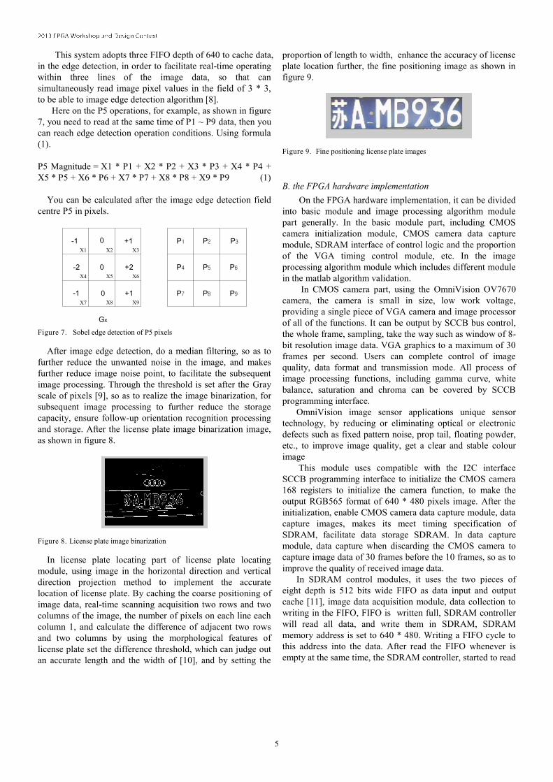
an accurate length and the width of [10], and by setting the
proportion of length to width, enhance the accuracy of license
plate location further, the fine positioning image as shown in
figure 9.
Figure 9. Fine positioning license plate images
B. the FPGA hardware implementation
On the FPGA hardware implementation, it can be divided
into basic module and image processing algorithm module
part generally. In the basic module part, including CMOS
camera initialization module, CMOS camera data capture
module, SDRAM interface of control logic and the proportion
of the VGA timing control module, etc. In the image
processing algorithm module which includes different module
in the matlab algorithm validation.
In CMOS camera part, using the OmniVision OV7670
camera, the camera is small in size, low work voltage,
providing a single piece of VGA camera and image processor
of all of the functions. It can be output by SCCB bus control,
the whole frame, sampling, take the way such as window of 8-
bit resolution image data. VGA graphics to a maximum of 30
frames per second. Users can complete control of image
quality, data format and transmission mode. All process of
image processing functions, including gamma curve, white
balance, saturation and chroma can be covered by SCCB
programming interface.
OmniVision image sensor applications unique sensor
technology, by reducing or eliminating optical or electronic
defects such as fixed pattern noise, prop tail, floating powder,
etc., to improve image quality, get a clear and stable colour
image
This module uses compatible with the I2C interface
SCCB programming interface to initialize the CMOS camera
168 registers to initialize the camera function, to make the
output RGB565 format of 640 * 480 pixels image. After the
initialization, enable CMOS camera data capture module, data
capture images, makes its meet timing specification of
SDRAM, facilitate data storage SDRAM. In data capture
module, data capture when discarding the CMOS camera to
capture image data of 30 frames before the 10 frames, so as to
improve the quality of received image data.
In SDRAM control modules, it uses the two pieces of
eight depth is 512 bits wide FIFO as data input and output
cache [11], image data acquisition module, data collection to
writing in the FIFO, FIFO is written full, SDRAM controller
will read all data, and write them in SDRAM, SDRAM
memory address is set to 640 * 480. Writing a FIFO cycle to
this address into the data. After read the FIFO whenever is
empty at the same time, the SDRAM controller, started to read
Page 6
6
the data, will read 512 bytes of data, cache and read the FIFO,
VGA control module to read. SDRAM controller address
range of data read and write FIFO address range is the same,
and are written to or read cycles.
In VGA control module, reading the data from SDRAM
cache read the FIFO, and with 640 * 480 @ the standard
sequence of 60 Hz, the output of the VGA line
synchronization, field synchronization signal and RGB image
data.
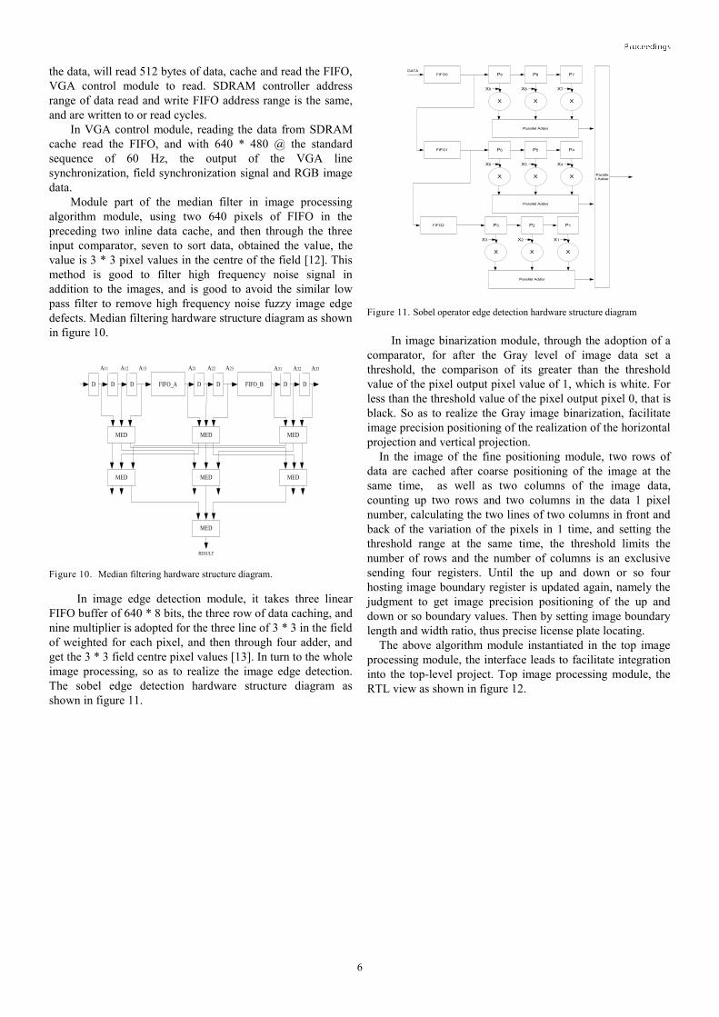
Module part of the median filter in image processing
algorithm module, using two 640 pixels of FIFO in the
preceding two inline data cache, and then through the three
input comparator, seven to sort data, obtained the value, the
value is 3 * 3 pixel values in the centre of the field [12]. This
method is good to filter high frequency noise signal in
addition to the images, and is good to avoid the similar low
pass filter to remove high frequency noise fuzzy image edge
defects. Median filtering hardware structure diagram as shown
in figure 10.
D FIFO_AD D D D FIFO_B D D
MED MED MED
MED MED MED
MED
A11 A12 A13 A21 A22 A23 A31 A32 A33
RESULT
Figure 10. Median filtering hardware structure diagram.
In image edge detection module, it takes three linear
FIFO buffer of 640 * 8 bits, the three row of data caching, and
nine multiplier is adopted for the three line of 3 * 3 in the field
of weighted for each pixel, and then through four adder, and
get the 3 * 3 field centre pixel values [13]. In turn to the whole
image processing, so as to realize the image edge detection.
The sobel edge detection hardware structure diagram as
shown in figure 11.
FIFO0 P9 P8 P7
Parallel Adder
X X X
X9 X8 X7
FIFO1 P6 P5 P4
Parallel Adder
X X X
X6 X5 X4
FIFO2 P3 P2 P1
Parallel Adder
X X X
X3 X2 X1
DATA
Paralle
l Adder
Figure 11. Sobel operator edge detection hardware structure diagram
In image binarization module, through the adoption of a
comparator, for after the Gray level of image data set a
threshold, the comparison of its greater than the threshold
value of the pixel output pixel value of 1, which is white. For
less than the threshold value of the pixel output pixel 0, that is
black. So as to realize the Gray image binarization, facilitate
image precision positioning of the realization of the horizontal
projection and vertical projection.
In the image of the fine positioning module, two rows of
data are cached after coarse positioning of the image at the
same time, as well as two columns of the image data,
counting up two rows and two columns in the data 1 pixel
number, calculating the two lines of two columns in front and
back of the variation of the pixels in 1 time, and setting the
threshold range at the same time, the threshold limits the
number of rows and the number of columns is an exclusive
sending four registers. Until the up and down or so four
hosting image boundary register is updated again, namely the
judgment to get image precision positioning of the up and
down or so boundary values. Then by setting image boundary
length and width ratio, thus precise license plate locating.
The above algorithm module instantiated in the top image
processing module, the interface leads to facilitate integration
into the top-level project. Top image processing module, the
RTL view as shown in figure 12.
Page 7
7
Figure 12. Image processing RTL-level view of the top module
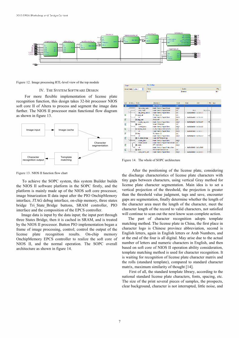
IV. THE SYSTEM SOFTWARE DESIGN
For more flexible implementation of license plate
recognition function, this design takes 32-bit processor NIOS
soft core II of Altera to process and segment the image data
further. The NIOS II processor main functional flow diagram
as shown in figure 13.
Image input Image cache
Character
segmentation
Template
matching
Character
recognition output
Figure 13. NIOS II function flow chart
To achieve the SOPC system, this system Builder builds
the NIOS II software platform in the SOPC firstly, and the
platform is mainly made up of the NIOS soft core processor,
image binarization II data input after the PIO OnchipMemory
interface, JTAG debug interface, on-chip memory, three states
bridge Tri_State_Bridge buttons, SRAM controller, PIO
interface and the composition of the EPCS controller.
Image data is input by the data input; the input port through
three States Bridge, then it is cached in SRAM, and is treated
by the NIOS II processor. Button PIO implementation began a
frame of image processing, control; control the output of the
license plate recognition results. On-chip memory
OnchipMemory EPCS controller to realize the soft core of
NIOS II, and the normal operation. The SOPC overall
architecture as shown in figure 14.
Figure 14. The whole of SOPC architecture
After the positioning of the license plate, considering
the discharge characteristics of license plate characters with
tiny gaps between characters, using vertical Gray method for
license plate character segmentation. Main idea is to set a
vertical projection of the threshold, the projection is greater
than the threshold value judgment, tags and save, encounter
gaps are segmentation, finally determine whether the length of
the character area meet the length of the character, meet the
character length of the record to valid characters, not satisfied
will continue to scan out the next know scan complete action.
The part of character recognition adopts template
matching method. The license plate in China, the first place in
character logo is Chinese province abbreviation, second is
English letters, again in English letters or Arab Numbers, and
at the end of the four is all digital. May arise due to the actual
number of letters and numeric characters in English, and then
based on soft core of NIOS II operation ability consideration,
template matching method is used for character recognition. It
is waiting for recognition of license plate character matrix and
the rolls (standard template), compared to standard character
matrix, maximum similarity of thought [14].
First of all, the standard template library, according to the
national standard license plate characters, fonts, spacing, etc.
The size of the print several pieces of samples, the prospects,
clear background, character is not interrupted, little noise, and
Page 8
8
contains all of the possible license plate characters, as the
"standard plate", standard character matrix library to sample
production. The character of the "standard plate" partition
normalization, and then of the normalized template matrix in
the FPGA as the standard template library, according to
experiment condition, the template, the greater the recognition
rate is higher, but at the same time it will bring operations to
increase the amount of data. So taking a comprehensive
consideration after accuracy and working efficiency of soft
core of NIOS II, the 20 x 15 bit size of the array is used as a
standard template.
When the license plate recognition character after
normalization, it matches with the standard of library template
in turn, namely, matrix corresponding to the who do bad in
turn, and calculates the total pixel number, the group that has
the largest same numbers is the number of similarity's biggest,
with a standard template for Numbers or letters at this time as
the final recognition results.
Some commonly used license plate characters include the
following parts:
1. the part of Chinese characters includes : Beijing, Tianjin,
Shanxi, Hebei, Mongolia, Liaoning, Jilin, Heilongjiang,
Shanghai, Jiangsu, Zhejiang, Anhui, Fujian, Jiangxi,
Shandong, Henan, Hubei, Hunan, Guangdong, Guangxi,
Hainan, Sichuan, Guizhou, clouds, Tibetan, Shaanxi, Gansu,
Qinghai, Ningxia, new, Chongqing;
2. digital part includes: 0,1,2,3,4,5,6,7,8,9;
3. letter includes: A, B, C, D, E, F, G, H, J, K, L, M, N, O, P,
Q, R, S, T, U, V, W, X, Y, Z.
Letter I is not used generally, because it is easily confused
with the number 1.
Figure 15. RTL-level view of the overall design
Figure 16. FPGA resource usage
V. CONCLUSIONS
By Altera EP2C35 FPGA platform on the actual board
level test, we have identified the license plate localization and
license plate image perfectly. The whole RTL structure Is
shown in Figure 15. The License plate positioning has good
efficiency, and uses relatively small FPGA logic resources as
shown in Figure 16. Through the license plate recognition
system based on FPGA designed, it makes you more in-depth
understand the application of FPGA in the aspect of image
processing, also the application of the NIOS II processor. This
design implements the actual hardware shown in Figure 17.
Through InnovateAsia, it lets me handle my own design more
systematically when I am designing the FPGA system. In the
design process, I also encountered many problems. For
example, because the FPGA development board lacks video
D/A converter, you need to draw the PCB by yourself; when
initializing OV7670 COMS cameras register configuration; in
Page 9
9
image processing, image colour extraction and edge detection
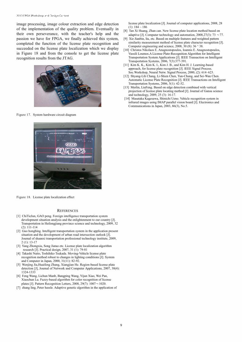
of the implementation of the quality problem. Eventually in
their own perseverance, with the teacher's help and the
passion we have for FPGA, we finally achieved this system,
completed the function of the license plate recognition and
succeeded on the license plate localization which we display
in Figure 18 and from the console to get the license plate
recognition results from the JTAG.
Figure 17. System hardware circuit diagram
Figure 18. License plate localization effect
REFERENCES
[1] ChiTieJun, GAO peng. Foreign intelligence transportation system
development situation analysis and the enlightenment to our country [J]. Transportation in Heilongjiang province science and technology, 2009, 32
(2): 111-114
[2] Guo hongbing. Intelligent transportation system in the application present situation and the development of urban road intersection outlook [J].
Journal of shaanxi transportation professional technology institute, 2009,
2 (1): 13-17 [3] Yang Zhongxiu, Song Jiatao etc. License plate localization algorithm
research [J]. Practical design, 2007, 31 (1): 79-81
[4] Takashi Naito, Toshihiko Tsukada. Moving-Vehicle license plate recognition method robust to changes in lighting conditions [J]. System
and Computer in Japan, 2000, 31(11): 82-92.
[5] Wenjing Jia,Huaifeng Zhang, Xiangjian He. Region-based license plate
detection [J], Journal of Network and Computer Applications, 2007, 30(4):
1324-1333
[6] Feng Wang, Lichun Manb, Bangping Wang, Yijun Xiao, Wei Pan, Xiaochun Lu. Fuzzy-based algorithm for color recognition of license
plates [J]. Pattern Recognition Letters, 2008, 29(7): 1007〜1020.
[7] zhang ling, Peter hassle. Adaptive genetic algorithm in the application of
license plate localization [J]. Journal of computer applications, 2008, 28 (1): 184 ~ 186
[8] Tan Xi Huang, Zhan can. New license plate location method based on
adaptive [J]. Computer technology and automation, 2008,27(3): 73 〜77.
[9] Xie Jianbin, liu, etc. Based on multiple features and weighted pattern
similarity measurement method of license plate character recognition [J].
Computer engineering and science, 2008, 30 (8): 36 ^ 38. [10] Christos Nikolaos E. Anagnostopoulos, Ioannis E. Anagnostopoulos,
Vassili Loumos.A License Plate-Recognition Algorithm for Intelligent Transportation System Applications [J]. IEEE Transaction on Intelligent
Transportation Systems, 2006, 7(3):377-391.
[11] Kim K. K., Kim K. I., Kim J. B., and Kim H. J. Learning-based approach, for license plate recognition [J]. IEEE Signal Process.
Soc.Workshop, Neural Netw. Signal Process, 2000, (2): 614–623.
[12] Shyang-Lih Chang, Li-Shien Chen, Yun-Chung, and Sei-Wan Chen. Automatic License Plate Recognition [J]. IEEE Transactions on Intelligent
Transportation Systems, 2006, 5(1): 42-52.
[13] Merlin, LiuFeng. Based on edge detection combined with vertical projection of license plate locating method [J]. Journal of Gansu science
and technology, 2009, 25 (3): 16-17.
[14] Masataka Kagesawa, Shinichi Ueno. Vehicle recognition system in infrared images using IMAP parallel vision board [J]. Electronics and
Communications in Japan, 2003, 86(3), No.5.