Faculdade de Engenharia da Universidade do Porto Intelligent Wheelchair Simulation Pedro Miguel Candeias de Castro Malheiro Dissertation executed under the Integrated Master in Electrotechnical and Computer Engineering Major in Automation Supervisor: Prof. Dr. Luis Paulo Reis July 2008
Transcript
Faculdade de Engenharia da Universidade do Porto
Intelligent Wheelchair Simulation
Pedro Miguel Candeias de Castro Malheiro
Dissertation executed under the Integrated Master in Electrotechnical and Computer Engineering
Figure 3.1 - Architecture of the “Ciber-Rato” robotic simulator system .......................... 14
Figure 3.2 - XML message for robotic agent registration. ............................................ 14
Figure 3.3 - UML sequence diagram of robotic and viewing agents‟ messaging with the simulator. ............................................................................................... 15
Figure 3.4 - Ciber-Rato‟s robots‟ body and sensors. ................................................... 15
Figure 3.5 - XML message for robot counter-clockwise rotation .................................... 16
Figure 3.6 - Robot direction information, sent by Ciber-Rato's compass sensor. ................ 16
Figure 3.7 - Ciber-Rato Viewer‟s design of a XML modeled wall. ................................... 18
Figure 3.8 - Original "Ciber-Rato" Viewer information display ....................................... 19
Figure 4.5 - Overlaps of a rectangle shaped robot with a circular shaped one. .................. 27
Figure 4.6 - Virtual Body for modeled by Intellwheels simulator. .................................. 27
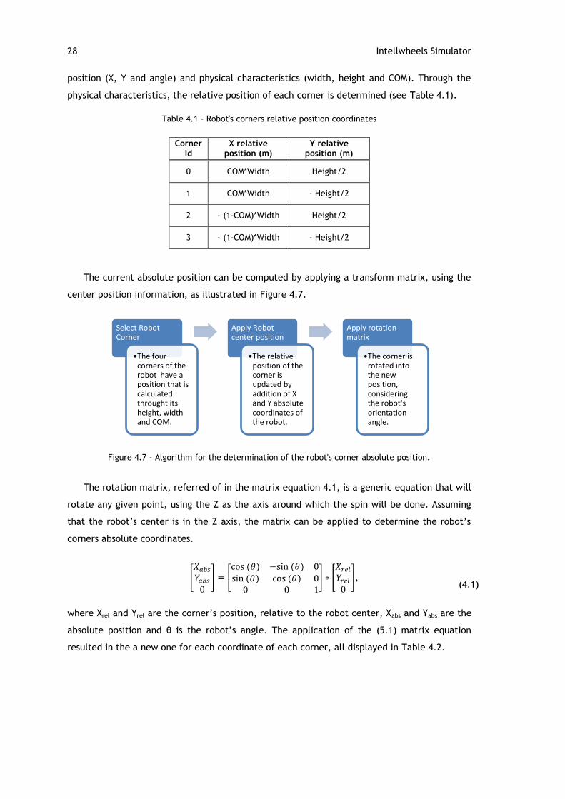
Figure 4.7 - Algorithm for the determination of the robot's corner absolute position. ......... 28
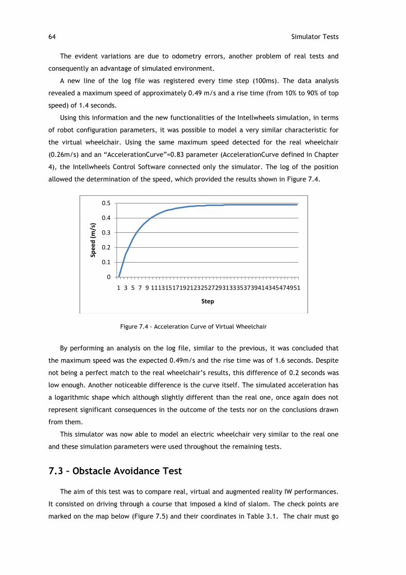
Figure 4.8 - Output charts of a situation where curve=0.2 (on the right) and curve=0.8 (on the left) and both with constant input at 100%. ................................................. 30
Figure 4.9 - Line Intersection Verification .............................................................. 32
Figure 4.10 - Cycle for checking collision on all lines from every robot ........................... 33
Figure 4.11 - UML diagram of the “Determine Intersection” function. ............................ 33
Figure 4.12 - Comparison between the modeled body‟s and sensors of the simulated robots in Ciber-Rato (a) and Intellwheels (b). ................................................... 34
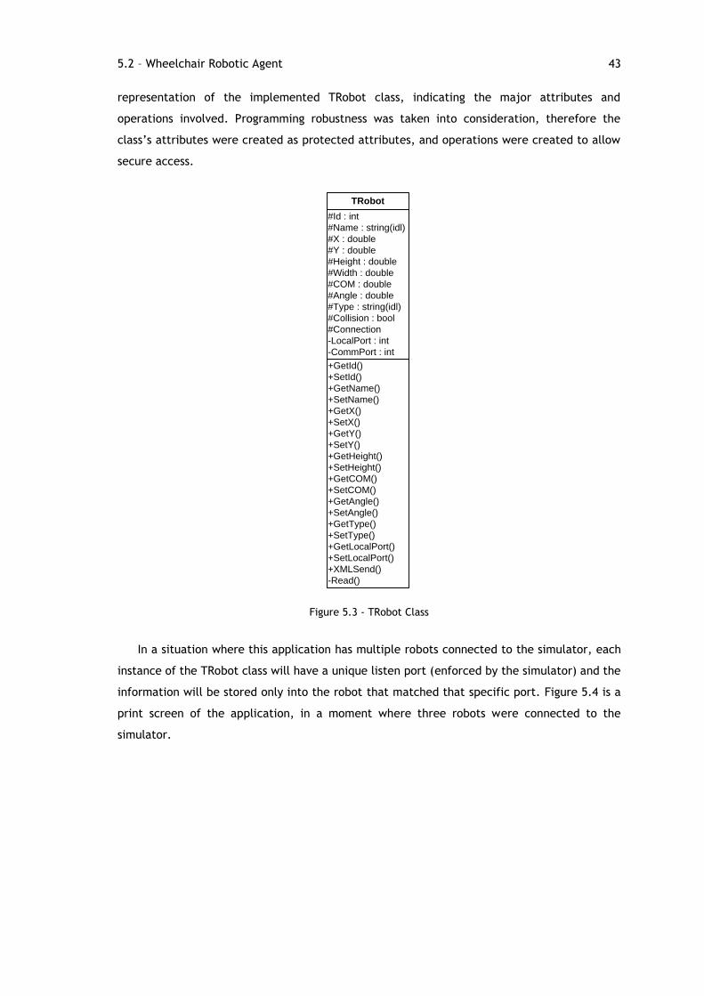
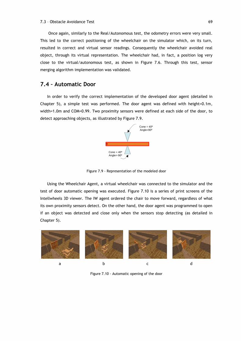
Figure 5.5 – UML stat diagram of the door control algorithm ........................................ 45
Figure 5.6 - Simulation-Ready structures on Intellwheels main application (adapted from [1]) ....................................................................................................... 46
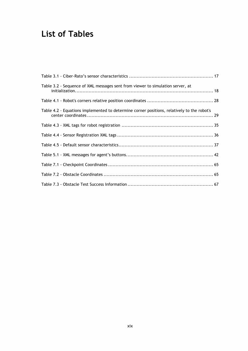
Table 3.2 - Sequence of XML messages sent from viewer to simulation server, at initialization. ........................................................................................... 18
Table 4.1 - Robot's corners relative position coordinates ............................................ 28
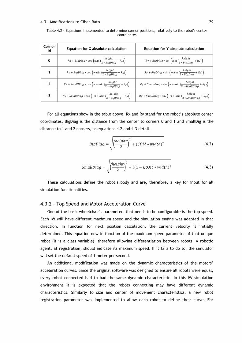
Table 4.2 - Equations implemented to determine corner positions, relatively to the robot's center coordinates .................................................................................... 29
Table 4.3 - XML tags for robot registration ............................................................. 35
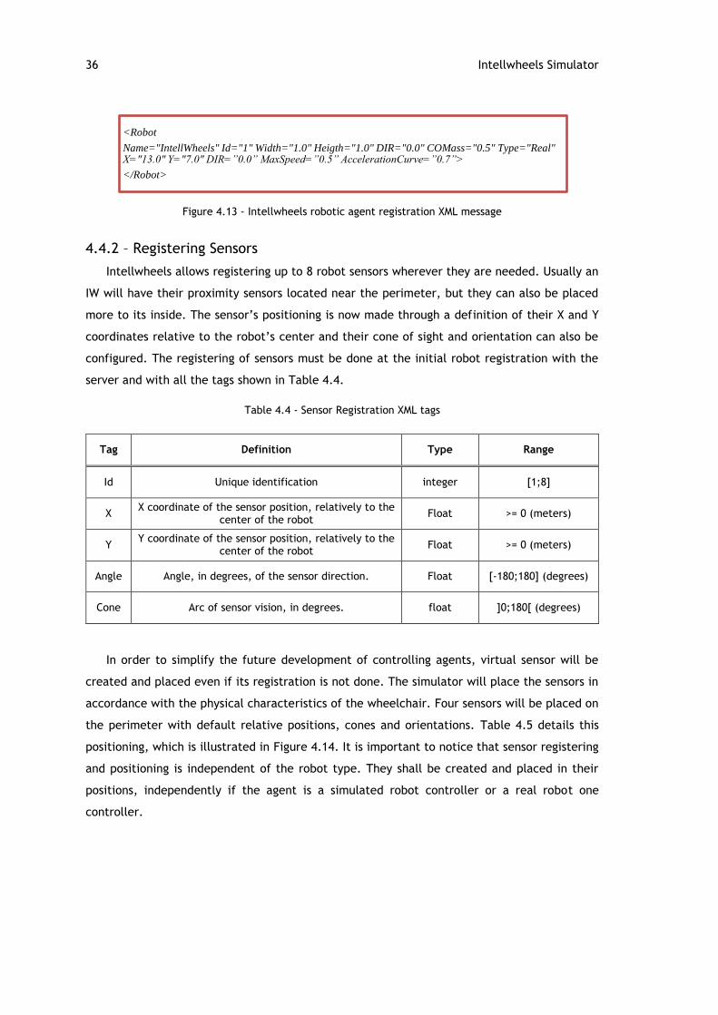
Table 4.4 - Sensor Registration XML tags ................................................................ 36
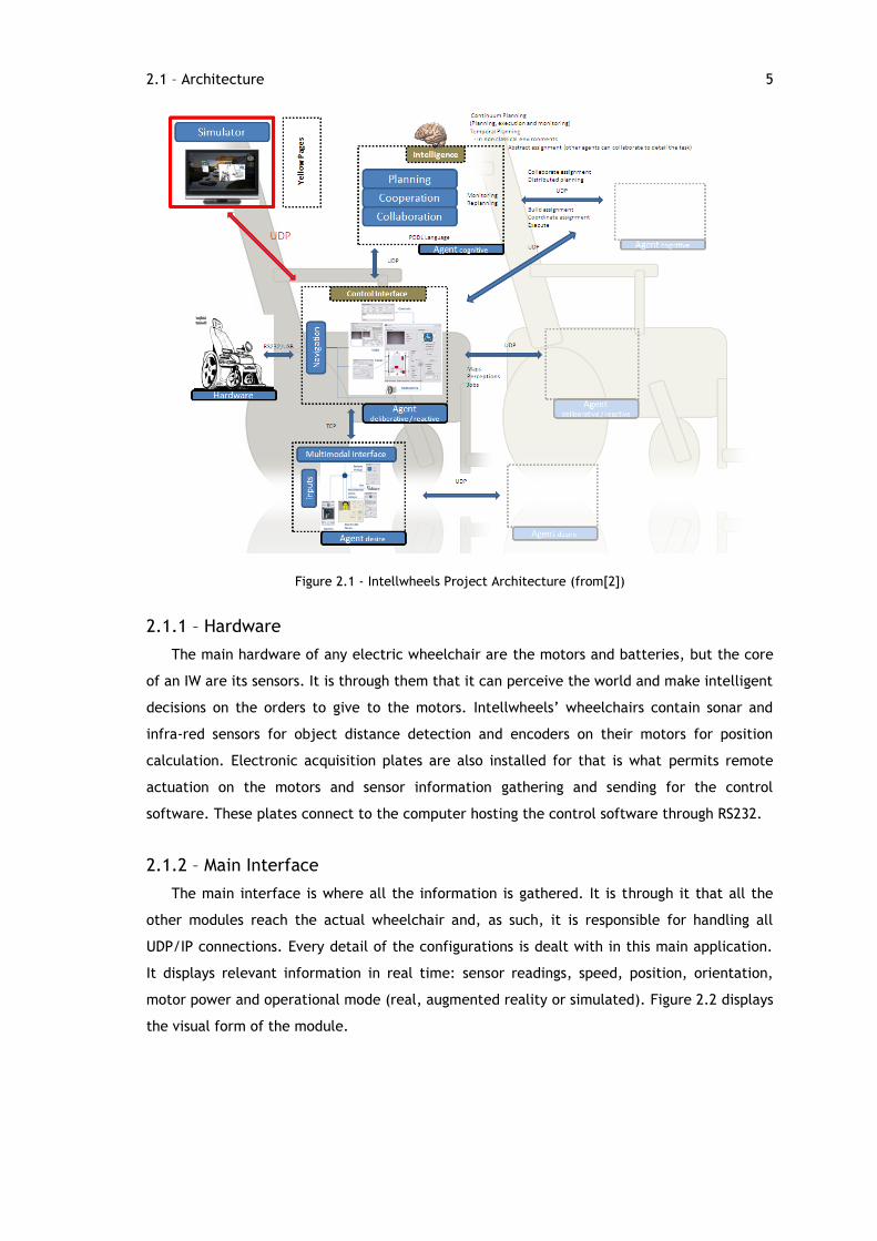
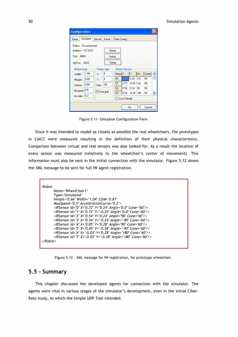
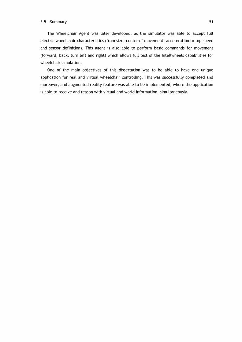
The main hardware of any electric wheelchair are the motors and batteries, but the core
of an IW are its sensors. It is through them that it can perceive the world and make intelligent
decisions on the orders to give to the motors. Intellwheels‟ wheelchairs contain sonar and
infra-red sensors for object distance detection and encoders on their motors for position
calculation. Electronic acquisition plates are also installed for that is what permits remote
actuation on the motors and sensor information gathering and sending for the control
software. These plates connect to the computer hosting the control software through RS232.
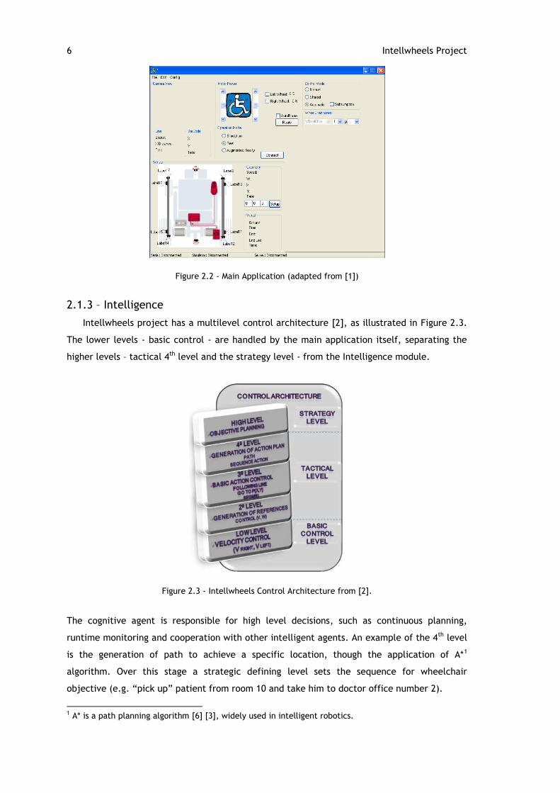
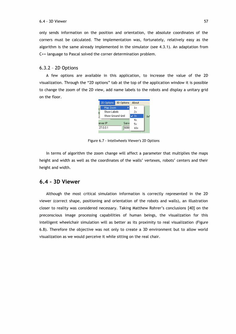
2.1.2 – Main Interface
The main interface is where all the information is gathered. It is through it that all the
other modules reach the actual wheelchair and, as such, it is responsible for handling all
UDP/IP connections. Every detail of the configurations is dealt with in this main application.
It displays relevant information in real time: sensor readings, speed, position, orientation,
motor power and operational mode (real, augmented reality or simulated). Figure 2.2 displays
the visual form of the module.
6 Intellwheels Project
Figure 2.2 - Main Application (adapted from [1])
2.1.3 – Intelligence
Intellwheels project has a multilevel control architecture [2], as illustrated in Figure 2.3.
The lower levels - basic control - are handled by the main application itself, separating the
higher levels – tactical 4th level and the strategy level - from the Intelligence module.
Figure 2.3 - Intellwheels Control Architecture from [2].
The cognitive agent is responsible for high level decisions, such as continuous planning,
runtime monitoring and cooperation with other intelligent agents. An example of the 4th level
is the generation of path to achieve a specific location, though the application of A*1
algorithm. Over this stage a strategic defining level sets the sequence for wheelchair
objective (e.g. “pick up” patient from room 10 and take him to doctor office number 2).
1 A* is a path planning algorithm [6] [3], widely used in intelligent robotics.
2.1 – Architecture 7
The result of this module will be a series of low level instructions to be given to the
wheelchair‟s motors through the main application, independently of details of how those
orders are given.
2.1.4 – Multimodal Interface
Making the wheelchair‟s control correctly and fully understand the user‟s orders is
essential, otherwise the control algorithms and intelligence could work against the patient
instead of working for him. Simultaneously to the development of this dissertation, Marcio
Sousa is developing a project designated “Multimodal Interface for an Intelligent
Wheelchair”. This multimodal interface is where all the possible user inputs are handled and
it has two main objectives:
Recognizing sequences of commands which represent specific high medium level
orders. This functionality works in a very similar form to “combos” in computer
games, where depending on the order of the buttons pressed, the arrow keys could
originate different moves.
Creating the possibility of receiving those orders through as many different inputs as
needed: voice recognition, face recognition, joystick or keyboard.
2.1.5 – Simulator
The simulation module was the main focus of this dissertation and a vital one on the
Intellwheels project.
This module creates a virtual world and its main objective is to test the control
algorithms. In fact, using the real environment every time the control application is modified
is not viable. On the other hand, it is not possible to validate a change without a form of
testing it. The control application may connect to the simulator, instead of the real
wheelchair, and all the consequences of a modification can be verified in a matter of
seconds.
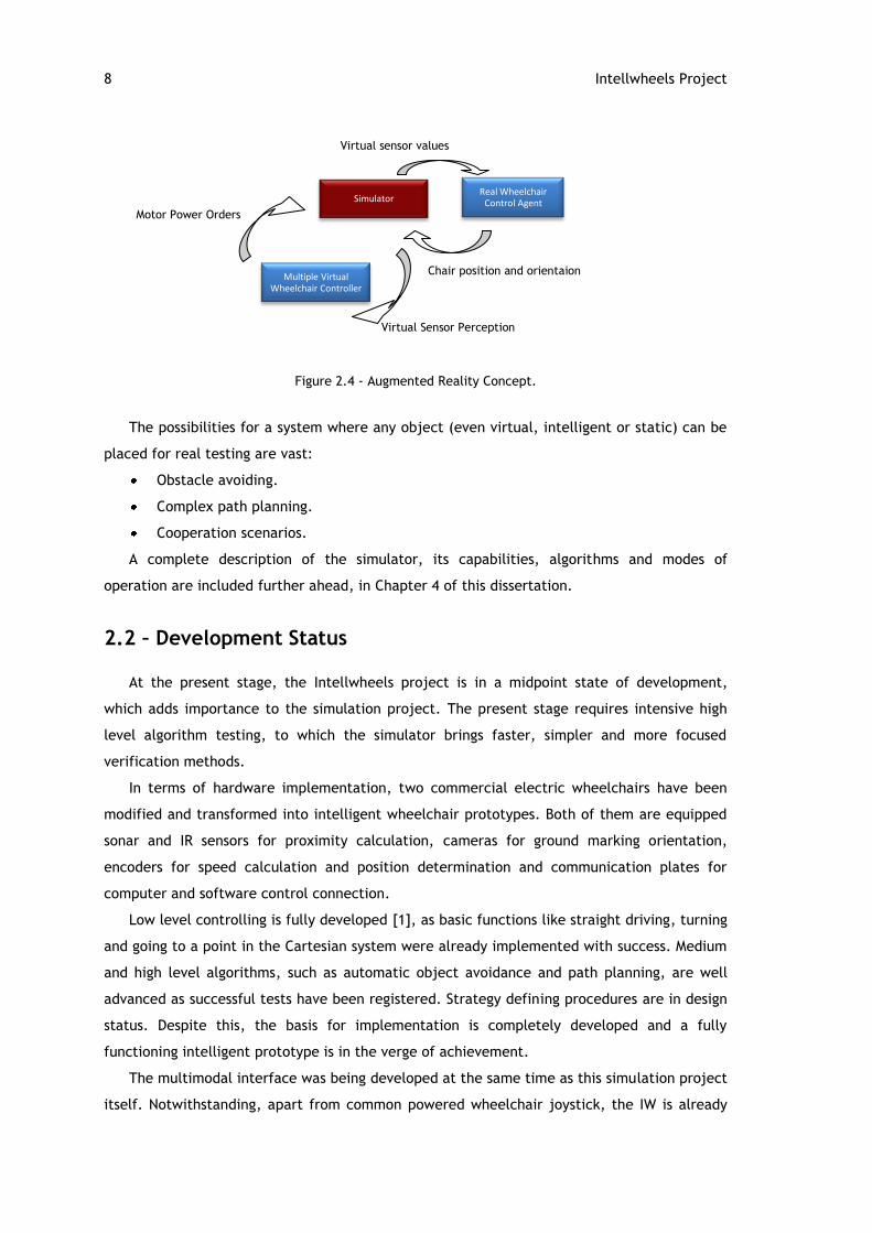
However, the simulator‟s involvement in the IW project is even greater, as the notion of
augmented reality is introduced. An interaction of real wheelchair with virtual ones sets the
tone for a complete new range of possible testing. Large scale cooperative tests (intelligence
module) are possible, no matter how little real IW prototypes are available (Figure 2.4).
8 Intellwheels Project
Virtual sensor values
Figure 2.4 - Augmented Reality Concept.
The possibilities for a system where any object (even virtual, intelligent or static) can be
placed for real testing are vast:
Obstacle avoiding.
Complex path planning.
Cooperation scenarios.
A complete description of the simulator, its capabilities, algorithms and modes of
operation are included further ahead, in Chapter 4 of this dissertation.
2.2 – Development Status
At the present stage, the Intellwheels project is in a midpoint state of development,
which adds importance to the simulation project. The present stage requires intensive high
level algorithm testing, to which the simulator brings faster, simpler and more focused
verification methods.
In terms of hardware implementation, two commercial electric wheelchairs have been
modified and transformed into intelligent wheelchair prototypes. Both of them are equipped
sonar and IR sensors for proximity calculation, cameras for ground marking orientation,
encoders for speed calculation and position determination and communication plates for
computer and software control connection.
Low level controlling is fully developed [1], as basic functions like straight driving, turning
and going to a point in the Cartesian system were already implemented with success. Medium
and high level algorithms, such as automatic object avoidance and path planning, are well
advanced as successful tests have been registered. Strategy defining procedures are in design
status. Despite this, the basis for implementation is completely developed and a fully
functioning intelligent prototype is in the verge of achievement.
The multimodal interface was being developed at the same time as this simulation project
itself. Notwithstanding, apart from common powered wheelchair joystick, the IW is already
Simulator
Multiple Virtual Wheelchair Controller
Real Wheelchair Control Agent
Chair position and orientaion
Motor Power Orders
Virtual Sensor Perception
2.3 – Summary 9
able to accept direct commands (forward, backward and turning) through the WII and
Playstation remote controllers and a virtual keyboard. The camera for face recognition was
developed apart from the Intellwheels project even though it is fully operative, its
integration with the current control application is not yet complete.
The Simulation module was completely achieved and it is now possible to fully test
control algorithms in any type of scenario, with as many virtual or real IW as intended.
Moreover, additional possibilities for its usage, such as full intelligent environment (e.g.
intelligent doors) were proposed which increase value of the module.
2.3 – Summary
This chapter presented the intelligent wheelchair project being developed in LIACC –
Intellwheels Project. It introduced the project‟s architecture, presenting all of its modules:
hardware, main application, intelligence, multimodal interface and simulation. It sums up by
presenting the current stage of development of each one of the modules.
This dissertation‟s main applicability will be on the Intellwheels and its simulator module.
As such, its architecture and the concepts presented on this chapter will be referred to in
every other section ahead. Moreover, the initial step for this thesis was the review of the
state-of-the-art in robotic simulation, which is done in the following chapter.
10 Robotic Simulation
Chapter 3
Robotic Simulation
This Simulation project was started with the decision to use the Ciber-Rato simulator
usage already taken (which is detailed in depth ahead, in section 3.2). The reasons that lead
to this are connected to the proven performance and flexibility of this software, as it has
been used in different applications and adaptations. It has been successfully used for various
competitions: Micro-Rato[11][8][12][13] (2001-2008), CiberMouse@RTSS[14] (2007-2008) and
CiberMouse@DCOSS[15] (2008). It was also previously used at LIACC in several research
projects such as a computational study on emotions and temperament in Multi-Agent
Systems[16][17] and development of cooperative rescue operations[18]. Moreover, previous
work had already been done in the Intellwheels project on Ciber-Rato usage for intelligent
wheelchair simulation, proving the software‟s value and suggesting further development on
the topic[3].
Despite the choice of the base application already dealt with, it was of relevance to study
similar simulation projects in order to incorporate additional concepts into this dissertation.
3.1 - Generic Robotic Simulators
A reference in robotic scientific development is RoboCup. RoboCup is, more than a
competition, a complete initiative with the vision of creating a robotic soccer team to win a
match against a human one [19]. During the meetings organized each year, robotic soccer and
search and rescue competitions are held. They have both simulated and real environment
contests, which have been used as inspiration for other robotic conferences around the world,
such as Micro-Rato[11] itself.
The RoboCup Simulation 2D League has various points in which it touches this IW
simulation project. This competition creates a virtual soccer field and models the two teams,
each with 11 players. In an attempt to closely mimic the real robot competition, the virtual
bodies of the players are circular, with differential virtual motors for movement control and
3.2 – Intelligent Wheelchair Simulators 11
possess sensors to aid decision making. Finally each team has a coach, which is a special
agent that holds unique information concerning the whole simulation. The coach differs from
the player agents in the sense that the data they receive are limited (e.g. by distance) are
have noise variation. Because of the differences between each agent inside a team, the focus
on this competition is on high level cooperation and control algorithms[20]. For visual
simulation following, 2D and 3D viewers are available, although the 3D characteristics are not
modeled by the simulator and only appear for better appeal.
Ciber-Rato follows the concepts of the RoboCup 2D League and, consequently, so does the
Intellwheels Simulator, developed during this dissertation.
A 3D League was later developed, which implemented profound modifications to the 2D
version, especially in terms of world modelling and communications handling, as the SPADES2
platform was introduced. Once again, in an effort to add more realism to the simulation
itself, apart from the full 3D environment, a visual sensor was the main form of perceiving
the world. Furthermore, the robot model evolved from the initial sphere to a humanoid, in
2007.
Other robotic simulators were studied during the initial part of this dissertation, which
include:
Gazebo / Player Project[21][22], a simulator for specific robot models, and is capable
of generating a wide number of robots with sensors in a three dimensional world.
UsarSim[23], a simulator that takes advantage of the realistic graphic and physics
power of the Unreal Engine, developed by Epic Games enterprise. Through TCP
protocol connections, this simulator allows the connection a control application and
provide it with a wide variety of sensors: encoders, touch, proximity, RFID, camera,
sound and motion sensors.
Microsoft released, in 2007, a generic robotic simulation environment called Microsoft
Robotics Studio[24]. Its target destination was not only the academic developers but
commercial ones as well, as the product could simulate a wide range of robotic
hardware. Moreover, visual programming language (VPL) was used, allowing easy
controlling. Rich environments could be set, as it uses the AGEIA PhysX[25] for world
physics calculations. The software rapidly proved its value, as illustrates the 2007
RoboCup[20].
3.2 – Intelligent Wheelchair Simulators
A literature review for other projects focused on intelligent wheelchair simulation was
performed and two projects stood out.
2 System for Parallel Agent and Discrete Event Simulation (SPADES) is an agent focused framework for communication handling, agent-world interaction and physics modeling [46].
12 Robotic Simulation
3.2.1 - Bremen Autonomous Wheelchair
The Bremen Autonomous Wheelchair (BAW)[26], initiated a simulation related project,
motivated by reasons that are shared with this Intellwheels intelligent wheelchair project. As
a consequence of developing new hardware platform, there is no commercial simulator that
can be directly used. Moreover, the final decision on sensory and communication equipment
is not yet defined thus creating the need for a software that is flexible enough to adapt. The
Bremen team started with a basic software, developed in their own university, called
SimRobot[27], and then set a methodology where they would systematically expand the
application each time they would find it necessary. They would submit the real chair to a test
and then apply the same test to the simulator. Afterwards, the results from both of them
were compared and, in case differences were found, they would upgrade the SimRobot
accordingly.
The entire simulation project is, therefore, an enduring evolution towards the equilibrium
between the real environment and the simulated one.
Differences, from the objectives of the Intellwheels project, arise when conceptual
architectures and simulation objectives are compared. While Bremen simulation is based on a
single chair, Intelwheels is multi-agent based, in the sense that a dynamic, more complex
environment with multiple intelligent and collaborative objects is intended. Furthermore,
BAW simulation segregates completely real and virtual worlds, leaving no room for augmented
reality model.
3.2.2 - Vehicule Autonome pour Handicapés Moteurs
An intelligent wheelchair developed in 1998 at the University of Metz, in France -
Vehicule Autonome pour Handicapés Moteurs (VAHM)[28] – was, in 2000, extended with a
simulation project[29]. The objective of this project was to solve a difficulty encountered
during the development: real disabled patient testing. Costly, time wasting and often
physically harmful, these tests became a burden that led to need of a simulator.
The simulator‟s concept was to enable the wheelchair with computer connection abilities
and create a software that would simulate the world perception to the chair. The chair was
to be the same has the real environment only with a breaking system disabling actual
movement, although allowing encoder perception. The patient is then equipped with a virtual
reality helmet with which he would see the virtual world. This blend of real variables with
the virtual world created mixed reality environment is very similar to what Intellwheels
project implements (which will be thoroughly detailed in chapter 4). The chair provides the
simulator with real encoder values and the software, in return, sends measures of virtual
ultrasonic sensors.
3.3 – University of Aveiro‟s Ciber-Rato 13
Overall architecture, on the other hand, is then distinguished from Intelwheels‟. VAHM‟s
simulation project range ends with the single chair test, while Intellwheels interest goes
further into higher level multiple IW collaborative algorithms.
3.3 – University of Aveiro’s Ciber-Rato
Ciber-Rato is a robotic simulation software developed for a competition, held at
University of Aveiro. The reason for its development was to provide a form of integrating
participants whose hardware skills weren‟t sufficient enough for real robot building, for the
older “Micro-Rato” competition. Through “Ciber-Rato” they could concentrate solely on the
control algorithms and software issues, as their robots are purely virtual[8].
The game consists of 3 “mice” (robotic agents that control their robot by sending motor
power inputs to the simulator) finding their way to a beacon. The agents are applications
developed by the contestants, thus separate of the simulator itself. They communicate with
it via UDP protocol and XML messaging. The virtual robots have a circular body and have
differential drive: a simulated motor for each of its two wheels (illustrated in Figure 3.4). At
start, the world is unknown to the agents and they rely on 3 IR sensors, 1 ground sensor, a
bumper sensor and a beacon compass to achieve the objective (in a testing mode, a GPS
sensor can be used for debugging but its usage is not allowed in the actual competition). The
agent that reaches the beacon with the best score (less time and less collisions) wins the
match.
The “Ciber-Rato” Simulator developers also created a modified version for a different
competition, in the 2008 edition of the International Conference on Distributed Computing in
Sensor Systems (DCOSS „08). The goal now is to make a team of 5 agents go to a single beacon
and the main difference, in terms of simulation, is that the robots can send messages to each
other. Their communication is limited by distance and message size, approaching a more
realistic scenario and encouraging development of information exchange algorithms.
3.3.1 – Architecture
Being “Ciber-Rato” itself based on the RoboCup simulation league, it follows the same
basic concepts: a distributed architecture where the simulation engine works as a server for
all other agents (clients) to connect to[8]. Figure 3.1 gives an overview on the system‟s
conceptual design.
14 Robotic Simulation
Figure 3.1 - Architecture of the “Ciber-Rato” robotic simulator system
Since every agent is an external application, they can all be developed in a different
programming language, having only the concern of using the same communication protocol as
the simulator. This possibility is particularly valuable since, in the actual competition, each
contestant can use their own computer and operating system.
3.3.2 – Communications
Information exchange between the agents and the simulator and even between the
simulator and the viewer are made through UDP and IP protocols. This allows not only to run
simulation with different applications for each agent but to run them from different
computers, as long as they are connected through an IP network.
The messages themselves are in XML language. Its usage allows not only an easy
processing by the programs but, on the other hand, it is concise, formal and human-legible
[30]. Figure 3.2 is an example of the XML message that needs to be sent to the simulator
server, to initiate the robot simulation.
Figure 3.2 - XML message for robotic agent registration.
It identifies the main tag has a Robot and defines its name has “IntellWheels” and its Id as
“1”.
In order to initiate a correct simulation, with robotic and visualization agents, a series of
XML messages should be sent to the simulator. A possible sequence is represented in the UML
sequence diagram on Figure 3.3.
Ciber-Rato
Simulator
Robot A Control
Robot B Control
Simulation Viewer
<Robot
Name="IntellWheels"
Id="1">
</Robot>
3.3 – University of Aveiro‟s Ciber-Rato 15
Viewer Simulator Robot
Registration
Confirm Registration
Request Map
Return Map Information
Request Grid
Registration Request
Confirm Registration
World perception
Motor Power Orders
Simulation EndSimulation End
Simulation StartSimulation Start. . . . . .
Figure 3.3 - UML sequence diagram of robotic and viewing agents‟ messaging with the simulator.
3.3.3 – Virtual Robot
The body of all simulated robots is circular, with a radius of 0.5 units. They are
differential robots, i.e., they are modeled with two wheels, as shown in Figure 3.4.
60º
60º
60º 60º
0.5u
Collision
Sensor
Proximity
Sensor
Figure 3.4 - Ciber-Rato‟s robots‟ body and sensors.
16 Robotic Simulation
The center of the circular body is also the center of movement of the robot as the wheels
are located symmetrically. Each wheel has its motor and can be controlled by the agent
through an XML message, containing the power to be applied in each motor.
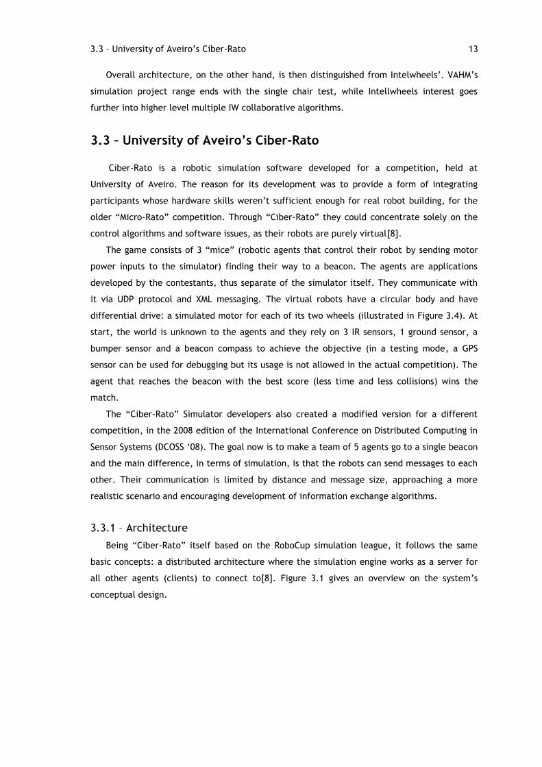
Figure 3.5 - XML message for robot counter-clockwise rotation
As an example, the command represented in Figure 3.5 will set the robot to rotate in its
own center.
By default every robot has their four proximity sensors placed in the perimeter, radially
oriented. The arc cone of the sensor‟s sight is fixed at 60º. On the DCOSS „08 version of
“Ciber-Rato”, the location of the sensors can be set by each robot. An angle, relative to the
robot‟s frontal direction, will define where, in the circle perimeter, will the sensors be
placed [31]. Although not completely configurable, this possibility gives the “Ciber-Rato”
simulator a more general and adaptable software for other uses, such has this intelligent
wheelchair simulation project.
A beacon sensor is also available. Through this sensor, the simulator will send the robot
controlling application a value in degrees (from -180º to 180º), indicating the direction of the
beacon, relatively to the robot‟s current direction. Approaching realistic conditions, if the
beacon if too far or if the obstacle between the robot and the beacon is too high, the
simulator will not send the beacon sensor reading.
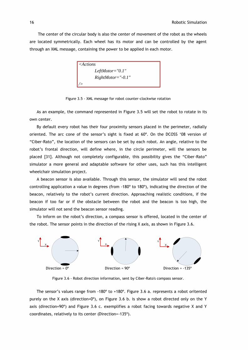
To inform on the robot‟s direction, a compass sensor is offered, located in the center of
the robot. The sensor points in the direction of the rising X axis, as shown in Figure 3.6.
Y
X
Y
X
Y
X
Direction = 0º Direction = 90º Direction = -135º
Figure 3.6 - Robot direction information, sent by Ciber-Rato's compass sensor.
The sensor‟s values range from -180º to +180º. Figure 3.6 a. represents a robot oritented
purely on the X axis (direction=0º), on Figure 3.6 b. is show a robot directed only on the Y
axis (direction=90º) and Figure 3.6 c. exemplifies a robot facing towards negative X and Y
coordinates, relatively to its center (Direction=-135º).
<Actions
LeftMotor="0.1"
RightMotor="-0.1"
/>
3.3 – University of Aveiro‟s Ciber-Rato 17
A GPS sensor is also available, returning information on X and Y positions and, also, on
robot orientation. These values have addictive noise (as exposed on Table 3.1), with different
maximum variations, which confers this sensor a distinct function to the regular compass.
Table 3.1 - Ciber-Rato‟s sensor characteristics
Sensor Range Resolution Noise Type Deviation
Proximity [0.0;100.0] 0.1 adivtive 0.1
Beacon [-180º;+180º] 1 Adivtive 2.0
Compass [-180º;+180º] 1 Adivtive 2.0
GPS (position) N/A 1 Adivtive 0.5
GPS (orientation) [-180º;+180º] 1 adivtive 5.0
Collision N/A
Ground N/A
The last two sensors defined in Table 3.1 – Collision sensor and Ground sensor – have
binary responses. The collision sensor will return “Yes” in case the robot touches any other
robot or a wall. The Ground sensor will return “Yes” if the robot‟s center is over a target
area, defined in the map XML document. In the competition, the target area is a circle with a
radius of 2.0 units.
3.3.4 – Robot-Robot Communication
The DCOSS version of Ciber-Rato was meant to encourage information exchange. To
achieve this, a robot-robot communication feature was implemented, only on this version,
which allows messaging between robots. They are not directly peer to peer. Instead, the
messages are sent via the simulation server (through UDP protocol, similarly to the motor
power orders) and broadcasted to every robot. This feature allows every robot to receive all
the information and decide itself whether to use it or not. To approach real situations, only
robots within 8 units of distance of the emissary robot will receive the message. It is possible
to send a message of a maximum of 100 bytes but, on the other hand, it is possible to receive
a total of 400 bytes at once.
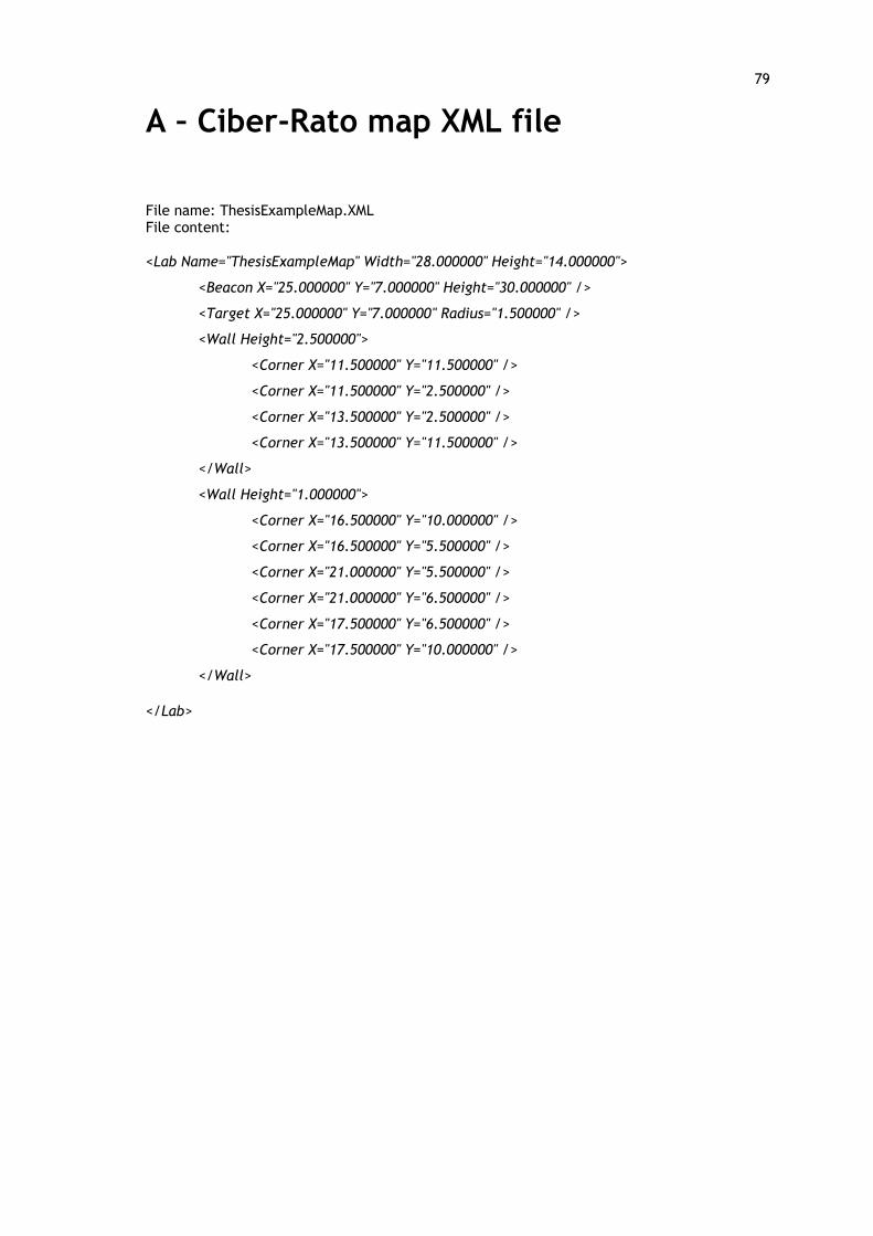
3.3.5 – Map and Wall Modeling
It is possible to load, from an external flat file, the map, in XML language. The map outer
limits are a rectangle which is defined by height and width information. Inside the limits
there can be walls which are defined by the coordinates of their corners and its height. For
competition purposes, a wall can have different heights, which affect the compass sensor of
the robot: if the wall is high the beacon will not be in the robot‟s line of sight, thus disabling
compass sensor readings. An ordered sequence of consecutive corner coordinates (minimum
of three corners) defines a wall and one map can contain any amount of walls (Annex A).
18 Robotic Simulation
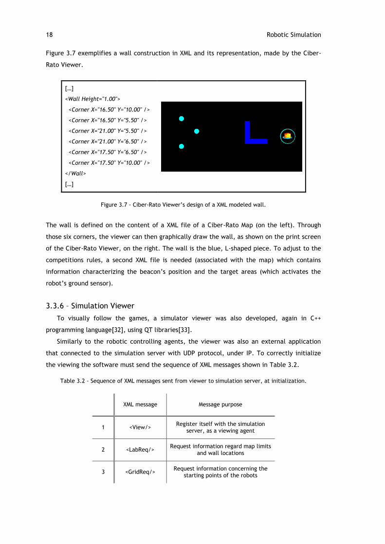
Figure 3.7 exemplifies a wall construction in XML and its representation, made by the Ciber-
Rato Viewer.
[…]
<Wall Height="1.00">
<Corner X="16.50" Y="10.00" />
<Corner X="16.50" Y="5.50" />
<Corner X="21.00" Y="5.50" />
<Corner X="21.00" Y="6.50" />
<Corner X="17.50" Y="6.50" />
<Corner X="17.50" Y="10.00" />
</Wall>
[…]
Figure 3.7 - Ciber-Rato Viewer‟s design of a XML modeled wall.
The wall is defined on the content of a XML file of a Ciber-Rato Map (on the left). Through
those six corners, the viewer can then graphically draw the wall, as shown on the print screen
of the Ciber-Rato Viewer, on the right. The wall is the blue, L-shaped piece. To adjust to the
competitions rules, a second XML file is needed (associated with the map) which contains
information characterizing the beacon‟s position and the target areas (which activates the
robot‟s ground sensor).
3.3.6 – Simulation Viewer
To visually follow the games, a simulator viewer was also developed, again in C++
programming language[32], using QT libraries[33].
Similarly to the robotic controlling agents, the viewer was also an external application
that connected to the simulation server with UDP protocol, under IP. To correctly initialize
the viewing the software must send the sequence of XML messages shown in Table 3.2.
Table 3.2 - Sequence of XML messages sent from viewer to simulation server, at initialization.
XML message Message purpose
1 <View/> Register itself with the simulation
server, as a viewing agent
2 <LabReq/> Request information regard map limits
and wall locations
3 <GridReq/> Request information concerning the
starting points of the robots
3.4 – Summary 19
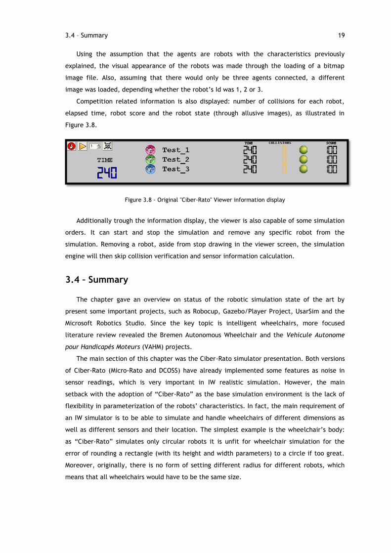
Using the assumption that the agents are robots with the characteristics previously
explained, the visual appearance of the robots was made through the loading of a bitmap
image file. Also, assuming that there would only be three agents connected, a different
image was loaded, depending whether the robot‟s Id was 1, 2 or 3.
Competition related information is also displayed: number of collisions for each robot,
elapsed time, robot score and the robot state (through allusive images), as illustrated in
Figure 3.8.
Figure 3.8 - Original "Ciber-Rato" Viewer information display
Additionally trough the information display, the viewer is also capable of some simulation
orders. It can start and stop the simulation and remove any specific robot from the
simulation. Removing a robot, aside from stop drawing in the viewer screen, the simulation
engine will then skip collision verification and sensor information calculation.
3.4 – Summary
The chapter gave an overview on status of the robotic simulation state of the art by
present some important projects, such as Robocup, Gazebo/Player Project, UsarSim and the
Microsoft Robotics Studio. Since the key topic is intelligent wheelchairs, more focused
literature review revealed the Bremen Autonomous Wheelchair and the Vehicule Autonome
pour Handicapés Moteurs (VAHM) projects.
The main section of this chapter was the Ciber-Rato simulator presentation. Both versions
of Ciber-Rato (Micro-Rato and DCOSS) have already implemented some features as noise in
sensor readings, which is very important in IW realistic simulation. However, the main
setback with the adoption of “Ciber-Rato” as the base simulation environment is the lack of
flexibility in parameterization of the robots‟ characteristics. In fact, the main requirement of
an IW simulator is to be able to simulate and handle wheelchairs of different dimensions as
well as different sensors and their location. The simplest example is the wheelchair‟s body:
as “Ciber-Rato” simulates only circular robots it is unfit for wheelchair simulation for the
error of rounding a rectangle (with its height and width parameters) to a circle if too great.
Moreover, originally, there is no form of setting different radius for different robots, which
means that all wheelchairs would have to be the same size.
20 Robotic Simulation
This scenario justifies the need for an IW-specific simulator that is generic enough to
model a wide variety of IWs and their sensors. In addition, the study revealed that Ciber-Rato
is a good base for the functionalities needed.
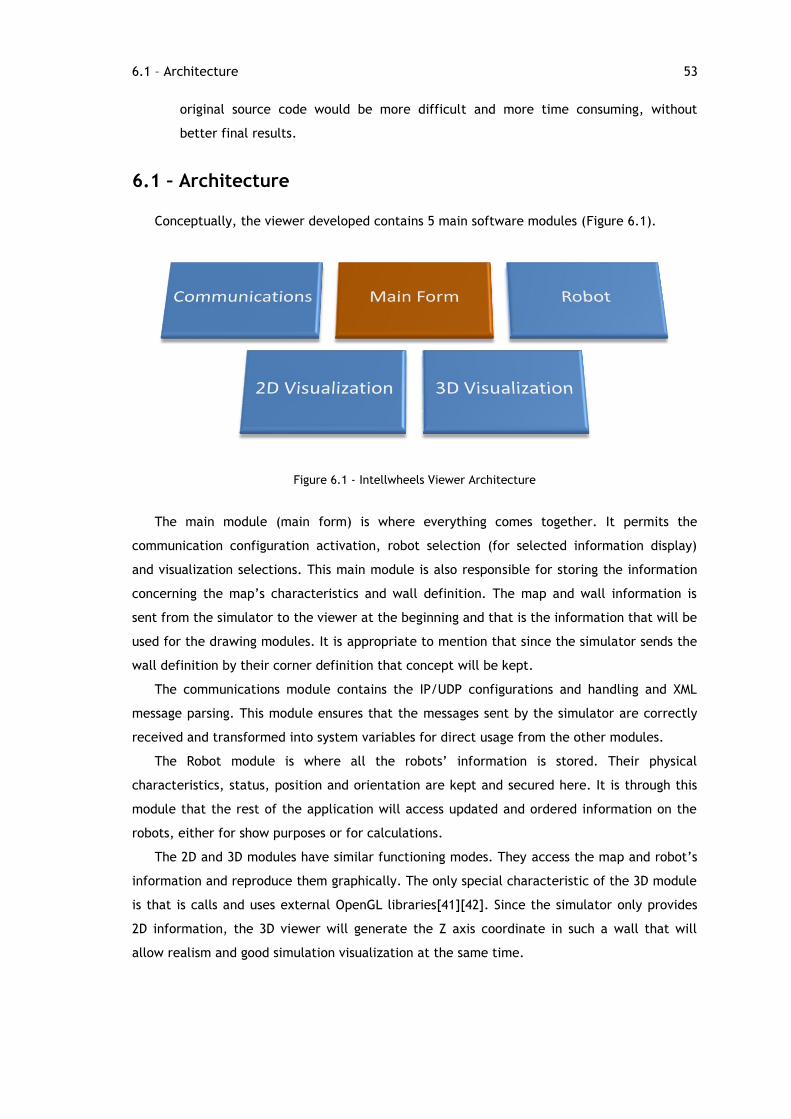
4.1 – Architecture 21
Chapter 4
Intellwheels Simulator
The main objective of this project was to develop simulation software to function as a
test board for control algorithms for intelligent wheelchairs. Converging with the larger
project it is inserted into (described in Chapter 2), the software was designated as
“Intellwheels Simulator”.
As core functions, this application creates a virtual world, complete with map definition,
where robotic agents can connect to. The simulator regulates the connection attempts,
handles the communications and returns to the agents the perception of the world, similarly
to what a real robot would get from the real environment around it, through its sensors.
The robot control software should treat the awareness information not discriminating it
from real or simulated, therefore producing the result independently: it produces orders
every connected actuators, being real or virtual. This scenario leads to the subject of reality
definitions. In fact, the usage of the same software for real situations as for virtual tests,
suggests a leap forward into the augmented reality concept, in which virtual world objects
interact with the real world.
This chapter will go through the simulator‟s conceptual architecture, including how the
support for mixed reality was implemented. It goes through the modifications made to Ciber-
Rato simulation environment and the new algorithms implemented to correctly simulate IWs.
4.1 – Architecture
Being essentially based in the Ciber-Rato source code, the Intellwheels Simulator has its
main basic architecture. Conceptually it is illustrated in Figure 4.1.
In a higher abstraction level, it consists of a central simulation server to which every
agent, independently of its type, will connect to. Furthermore, to have a structure as
modular as possible, the agents are external applications, developed in any kind of language
22 Intellwheels Simulator
and running in any type of operating system, must connect via IP and UDP protocols. Through
this obligation, the spectrum of possibilities for agent development is greatly broadened.
As a final implementation, the Intellwheels Control Software, previously developed in
LIACC, was adapted now allowing operability with the simulator. Through this
implementation, the developed simulator was proven a success. Not less important, the
algorithms already implemented on it could be tested with focus on their purposes. It is now
possible to ensure the functionality of a movement control algorithm (such as the obstacle
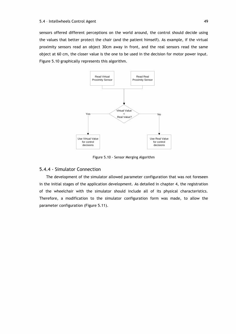
72 Conclusions
avoidance subsumption algorithm), eliminating sensor noise errors, since the virtual sensors
can provide error-free readings.
The simulator is now in use at the present stage of the Intellwheels Project development,
at LIACC, in different modules: “Main application” and “Intelligence” (see Chapter 2) for
control and stratergy algorithm tests and even in “Multimodal interface” for integration and
order validation.
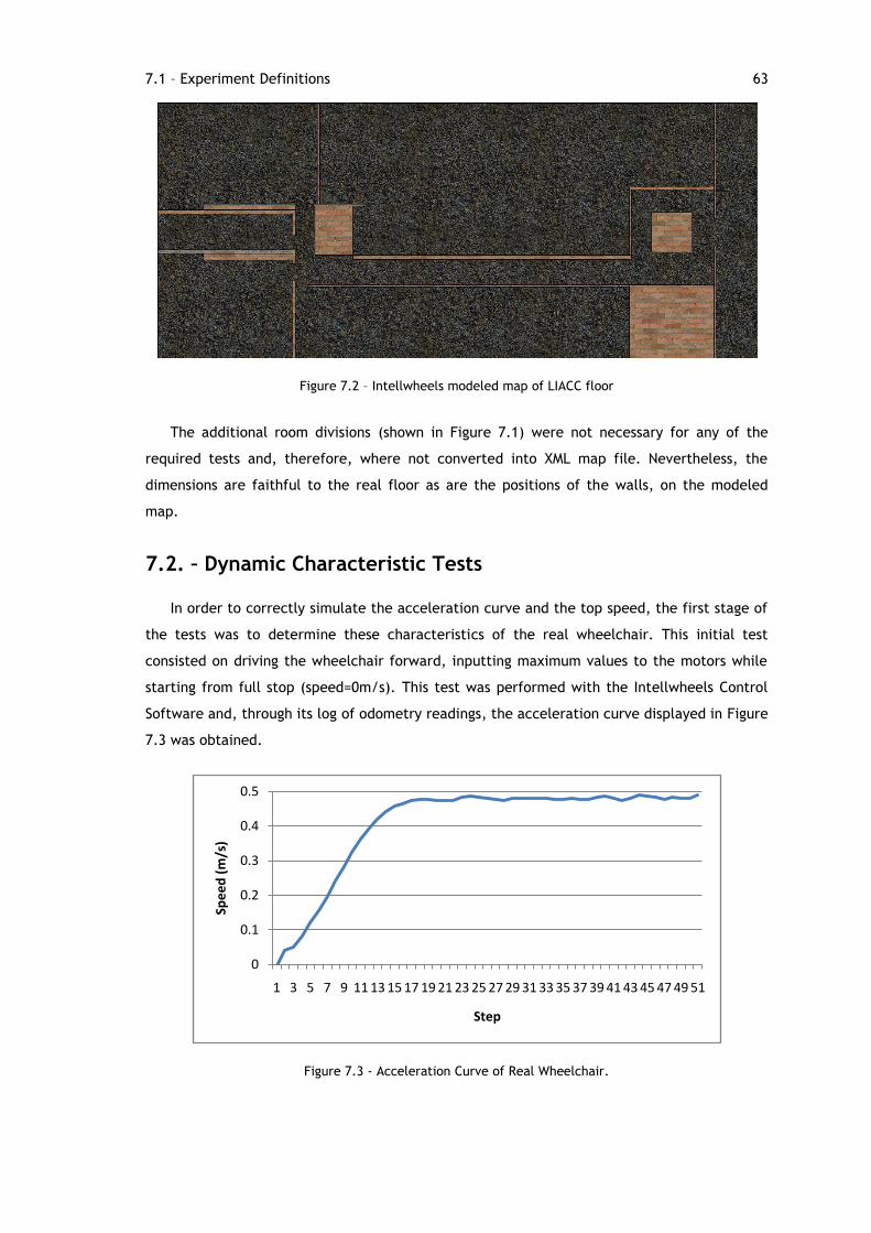
8.2 – Main Results
This simulator was submitted to tests with wheelchairs under manual and autonomous
driving. These tests were able to prove the concept that the simulator is a capable
application when generating all the virtual information that an intelligent agent requires for
autonomous navigation in an unknown environment.
The tests were also able to establish that, in a virtual environment, the IW autonomous
driving, performs better than in the real environment, navigating with encoders for speed and
position calculation and real sonar sensors for autonomous driving. From these results one is
able to infer that additional development is required on noise treatment for these sensors,
rather than holding the control algorithms responsible for failure in autonomous driving.
8.3 – Simulator’s Capabilities
The original intent of this simulator was to aid in the development of IWs and it is indeed
being used in such manner.
The simulator‟s capabilities stretch beyond IW wheelchair simulation, due to its origins
(Ciber-Rato) and to the generalization that was applied to it. In fact, this simulator can now
accept connections from any type of robotic agents, limited only to how the differential robot
modeled is able to move. Car and pedestrian simulation can be performed, not only through
their physical interaction (collisions) but emotional relations as well, since data
communication between agents is available. Having a distributed architecture, Intellwheels
Simulator expects the agents to be external applications that connect through UDP. Because
of this attribute, it is able to involve in a unique simulation a vast number of intelligent
agents, adding the possibility of testing algorithms results in a dynamic, complex
environment.
A limit may be imposed by the visualization software (Intellwheels Viewer), as it does not
yet have the full capability of dynamically loading any type of 3D object. Currently it
possesses a small range of 3D models and they are allocated to the type XML tag of the
object: only doors, tables and wheelchairs have dedicated 3D models, at the current version.
Nevertheless, the current application‟s source code is very flexible and basic shapes are
loaded in case a different type is identified, thus providing the sense of size and volume in
8.4 – Future Work 73
the virtual world‟s space. In fact, since it constructs the modules depending on the physical
characteristics provided by the simulator, the images offered will reflect the occupied space
of the object, independently of its nature.
Due to the origins of Intellwheels Simulator, it accepts robotic agents from the original
Ciber-Rato Simulato, with minor ajustments. The competition orientated mentality of the
agent needs to be modified, as well as sensor registration, but these are not core changes to
a controller software. Furthermore, the Ciber-Rato competition itself may evolve through the
new implemented parameters. The Intellwheels‟ concepts of using intelligent robotic agents
as dynamic scenario and the mixed reality feature (real and virtual environment interaction)
could add value and interest to the University of Aveiro‟s competition.
8.4 – Future Work
Time constraints were severe during the development of this research project. Thus, a
great number of features, that would add value to the simulation project, could not be
implemented in time for the imposed writing and presentation deadlines.
For the simulator itself, the most relevant issues are related with the inclusion of
additional sensors. Although not being presently in use by the Intellwheels Control Software,
a digital camera is physically mounted on the chair. Ground marking localization algorithms,
if implemented, using this camera, will add increased accuracy to the IW‟s awareness of its
position on the world. This action will help in the solution of one of the problems detected
during the tests performed on this dissertation.
Linked to this aspect are the encoder sensors. The real wheelchair uses encoders for
movement calculation but, on the other hand, the simulated robot receives this information
directly, through a virtual GPS. The possibility of encoder based navigation will increase
realism and allow testing navigation algorithms themselves.
A final note on what could be done concerning the sensor simulation concerns the
characteristic curve definition. Although the proximity sensors have configurable parameters,
the output equation itself is not re-definable. Allowing this would approximate the virtual
behavior even more to the real one.
Simulation agent development can still improve immensely, especially intelligent control
for objects (other than wheelchairs). An unexplored, although available, feature is the
communication module. Increased messaging capabilities between agents will allow:
Doors that open by communication orders instead of proximity perception.
Distributed planning: wheelchairs and other devices could jointly create plans to
fulfill some given tasks in a cooperative manner.
Strategy and tactics: wheelchairs could choose, between themselves, which one
would fulfill an order given by an outside entity. A gain in service quality will be
achieved with such an implementation.
74 Conclusions
Complex calculations, such as path planning, could benefit from distributing
computing between connected agents. Threads for the calculations could be spread
among the other agents, allowing a uniform capacity usage.
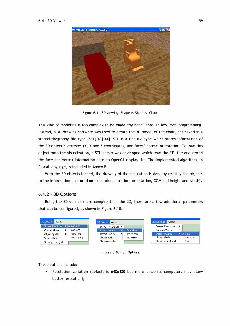
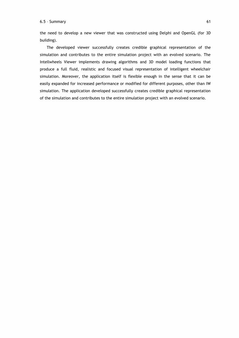
Finally, in respect of the Intellwheels Viewer application, developed for simulation
visualization, the potential is vast for future implementations. The user could use
information, specific for each robotic agent, sent from the simulator to load (or even
dynamically construct) a 3D model of the object. A possible implementation is to analyze the
name of the agent and, through it, guess an object type. With a list of 3D object models, it
would select the most appropriate and load it, through OpenGL, adjusting to the individual
size definitions.
Associated with this topic is the notion of scenario-related object agent integration. A
simulation, in order to be as interactive as possible, could allow direct insertion of objects,
during its run. An intuitive mean to do so is by visualizing the world and space onto which it
will be inserted. If the viewer had the capability of creating and controlling a table, cabinet
or door agents it would greatly simplify the inserting task and converging with the notion of
interaction importance on computer generated graphics [36].
A last functionality, that would increase the flexibility and the applicability of the viewer
application, is to fully integrate the viewer with the Ciber-Rato competition. Having been
designed for XML messaging, at the image of the original competition‟s software, the
additional coding would bring interesting results. A selectable operation mode, choosing from
IW Simulation or Ciber-Rato Simulation, would define how the robots are drawn: wheelchairs
or circular robots. This work would certainly bring added value to the competition and
probably interest more participants.
8.5 – Final Remarks
Having worked with the Ciber-Rato since the first day of this research project, the
following final comments arise. As a matter a fact, the software proved to be very flexible as
the adaptation modifications were implemented with success. Integration of the new
algorithms and functions within the original code itself was good, due to its well structured
characteristic.
This dissertation was made on a short period of time, however the developed applications
have proved to be of value to LIACC‟s Intellwheels Project as conclusions concerning the
previously developed control algorithms have already been taken. These new applications
developed are a very solid base for further work and the possibilities for expansion of agents,
viewer and the simulator itself are vast.
75
Bibliography
[1] M. R. Petry, "Desenvolvimento de um Protótipo e de Metodologias de Controlo de uma Cadeira de Rodas Inteligente," Dissertation for Masters Degree, Departamento de Engenharia Electrotecnica e de Computadores, Faculdade de Engenharia da Universidade do Porto, Porto, 2008.
[2] R. A. M. Braga, M. Petry, A. P. Moreira, and L. P. Reis, "INTELLWHEELS - A Development Platform for Intelligent Wheelchairs for Disabled People," in 5th International Conference on Informatics in Control, Automation and Robotics, vol. I, Funchal, Madeira, Portugal, 2008, pp. 115-121.
[3] R. A. M. Braga, M. Petry, E. Oliveira, and L. P. Reis, "Multi-Level Control Of An Intelligent Wheelchair In a Hospital Environment Using A Cyber-Mouse Simulation System," in 5th International Conference on Informatics in Control, Automation and Robotics, Funchal, Madeira, Portugal, 2008, pp. 179-182.
[4] P. M. Faria, R. A. M. Braga, E. Valgôde, and L. P. Reis, "Platform to Drive an Intelligent Wheelchair using Facial Expressions," in Proceedings 9th International Conference on Enterprise Information Systems - Human-Computer Interaction (ICEIS 2007), Funchal, Madeira, 2007, pp. 164-169.
[5] P. M. Faria, R. A. M. Braga, E. Valgôde, and L. P. Reis, "Interface framework to drive an intelligent wheelchair using facial expressions," in IEEE International Symposium on Industrial Electronics (ISIE 2007), 2007, pp. 1791-1796.
[6] R. A. M. Braga, M. R. Petry, A. P. Moreira, and L. P. Reis, "Platform for intelligent wheelchairs using multi-level control and probabilistic motion model," in 8th Portuguese Conference on Automatic Control, Controlo 2008, Vila Real, Portugal, 2008.
[7] J. Banks, "Introduction to Simulation," in Proceedings of the 2000 Winter Simulation Conference, vol. I, Phoenix, Arizona, United States, 2000, pp. 7-13.
[8] N. Lau, A. Pereira, A. Melo, A. Neves, and J. Figueiredo, "Ciber-Rato: Um Ambiente de Simulação de Robots Móveis e Autónomos," Revista do DETUA, 2002.
[9] N. Lau, A. Pereira, A. Melo, J. Neves, and J. Figueiredo, "Ciber-Rato: Uma Competição Robótica num Ambiente Virtual," Revista do DETUA, vol. 3, no. 7, pp. 647-650, Sep. 2002.
[10] Institute of Electrical and Electronics Engineers. (2008, Apr.) IEEE - The world's leading professional association. [Online]. www.ieee.org
[11] Universidade de Aveiro. (2008, Jun.) Concurso Micro-Rato. [Online]. http://microrato.ua.pt
[12] L. P. Reis, "Ciber-Feup - Ensino de Robótica e Inteligência Artificial através da Participação em Competições Robóticas," Electrónica e Comunicações, vol. 7, no. 3, Sep. 2002.
[13] L. Almeida, P. Fonseca, L. J. Azevedo, and B. Cunha, "The Micro-Rato Contest: Mobile Robotics for All," in CONTROLO 2000, The Portguese Control Conference, Guimarães, Portugal, 2000.
[14] RTSS - Real-Time Systems Symposium. (2008, Jun.) RTSS - Real-Time Systems Symposium. [Online]. http://www.rtss.org/
[16] D. Barteneva, N. Lau, and L. P. Reis, "Implementation of Emotional Behaviors in Multi-Agent System using Fuzzy Logic and Temperamental Decision Mechanism," in Proceedings of EUMAS 2006, Lisbon, Portugal, 2006, pp. 5-15.
[17] D. Barteneva, N. Lau, and L. P. Reis, "Bylayer Agent-Based Model of Social Behavior: How Temperament Influences on Team Performance," in 21st European Conference on Modelling and Simulation – ECMS 2007, Prague, Czech Republic, 2007, pp. 181-187.
[18] L. Lemos, F. Cruz, and L. P. Reis, "Sistema de Resgate e Salvamento Coordenado Utilizando o Simulador Ciber-Rato," in CISTI 2007 - 2ª Conferência Ibérica de Sistemas e Tecnologias de Informação, Novas Perspectivas em Sistemas e Tecnologias de Informação, Porto, Portugal, 2007.
[19] M. Chen, et al. (2002, Aug.) RoboCup Official Site. [Online]. http://www.robocup.org/
[20] N. Lau and L. P. Reis, "FC Portugal - High-level Coordination Methodologies in Soccer Robotics," in Robotic Soccer, Dec. 2007, p. 598.
[21] Gazebo / Player Project. (2008, Mar.) Gazebo / Player Project. [Online]. http://playerstage.sourceforge.net/index.php?src=gazebo
[22] B. Gerkey, R. Vaughan, and A. Howard, "The Player/Stage Project:Tools for Multi-Robot and Distributed Sensor Systems," in International Conference on Advanced Robotics, Coimbra, Portugal, 2003, pp. 317-323.
[23] S. Carpin, M. Lewis, J. Wang, S. Balakirsky, and C. Scrapper, "USARSim: a robot simulator for research and education," in IEEE International Conference onRobotics and Automation, 2007, pp. 1400-1405.
[24] Microsoft. (2008, Mar.) Microsoft Robotics. [Online]. http://msdn.microsoft.com/en-us/robotics/default.aspx
[26] T. Röfer, "Strategies for Using a Simulation in the Development of the Bremen Autonomous Wheelchair," in Proceedings of the 12th European Simulation Multiconference on Simulation - Past, Present and Future, 1998, pp. 460-464.
[27] Universität Bremen. (2008, Apr.) SimRobot - 3D-Robotiksimulator. [Online]. http://www.informatik.uni-bremen.de/simrobot/
[28] G. Bourhis and Y. Agostini, "The Vahm Robotized Wheelchair: System Architecture and Human-Machine Interaction," Journal of Intelligent and Robotic Systems, vol. 22, no. 1, pp. 39-50, May 1998.
[29] H. Niniss and A. Nadif, "Simulation of the behaviour of a powered wheelchair using virtual reality," in Proc. 3rd Intl Conf. Disability, Virtual Reality & Assoc. Tech, Alghero, Italy, 2000.
[30] J. C. Lopes and C. Ribeiro. (2008, Feb.) João Correia Lopes | Homepage. [Online]. http://paginas.fe.up.pt/~jlopes/teach/2007-08/LAPD/lectures/01-XML-intro.pdf
[31] Departamento de Electrónica, Telecomunicações e Informática. (2008, Mar.) CiberMouse at DCOSS08. [Online]. http://www.ieeta.pt/lse/ciberdcoss08/docs/ciberDCOSS08_Rules.pdf
[32] B. Stroustrup, The C++ programming language, 2nd ed.. USA: Addison-Wesley Longman Publishing Co., Inc, 1991.
[33] M. K. Dalheimer, Programming with Qt, 2nd ed.. O'Reilly, 2002.
[34] R. Azuna, et al., "Recent Advances in Augmented Reality," IEEE Computer Graphics and Applications, vol. 21, no. 6, pp. 34-37, Nov. 2001.
[35] P. Milgram and F. Kishino, "A Taxonomy of Mixed Reality Visual Displays," in IEICE Transactions on Information Systems, vol. E77-D, 1994, pp. 1321-1329.
[36] Trolltech. Code Less. Create More. Deploy Everywhere. - Trolltech.
[38] M. Cantù, Mastering Delphi 7, 1st ed.. Sybex, 2003.
[39] D. P. Reed. (1980, Aug.) Internet Engeneering Task Force. [Online]. http://tools.ietf.org/html/rfc768
[40] M. R. Rohrer, "Seeing is Believing: The Importance Of Visualization in Manufacturing Simulation," in Winter Simulation Conference, 2000, pp. 1211-1216.
[41] OpenGL. (2008, May) The Industry's Foundation for High Performance Graphics. [Online]. http://www.opengl.org/
[42] M. Woo, J. Neider, and T. Davis, OpenGL Programming Guide, Third Edition: The Official Guide to Learning OpenGL, Version 1.2. Addison-Wesley, 1999.
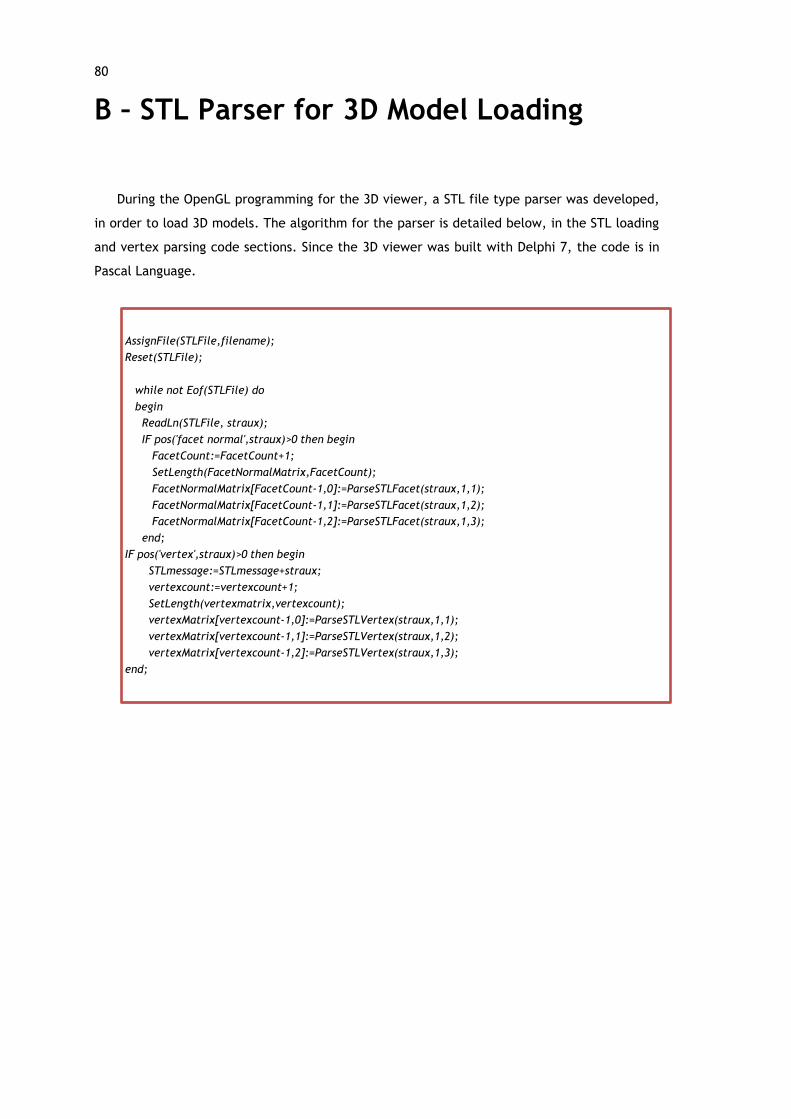
[43] E. Béchet, J. C. Cuilliere, and F. Trochu, "Generation of a finite element MESH from stereolithography (STL) files," Computer-Aided Design, vol. 34, no. 1, pp. 1-17, Jan. 2002.
[44] M. Burns, "The StL Format," in Automated Fabrication. Prentice Hall, 1989, ch. Section 6.5.
[45] A. Neves, J. Figueiredo, N. Lau, A. Pereira, and A. Melo, "O Visualizador do Ambiente de Simulação Ciber-Rato," Revista do DETUA, vol. 3, no. 7, pp. 651-654, Sep. 2002.
[46] P. Riley and G. Riley, "SPADES - a distributed agent simulation environment with software-in-the-loop execution," in Winter Simulation Conference, vol. 1, 2003, pp. 817-825.
[47] T. Bräunl, "The EyeSim Mobile Robot Simulator," Computer Science Department of The University of Auckland, 2000.
[48] B. Martins, E. Valgôde, P. Faria, and L. P. Reis, "Multimedia Interface with an Intelligent Wheelchair," in Proc. of CompImage 2006 –Computational Modelling of Objects Represented in Images: Fundamentals Methods and Applications, Coimbra, Portugal, 2006, pp. 267-274.
[49] M. Burns, "The STL File Format," in Automated Fabrication - Improving Productivity in Manufacturing. Prentice Hall, 1993, ch. Section 6.5.
[50] Faculdade de Engenharia da Universidade do Porto. (2008, Jun.) Faculdade de Engenharia da Universidade do Porto. [Online]. http://www.fe.up.pt/