39
Interactive Simulation and Visualization ~ Tools for Design ~ Curs 11 24.05. 2017

Interactive Simulation
and Visualization
~ Tools for Design ~
Curs 11
24.05. 2017

Mathematical models used in scientific computing are becoming large and complex. In order to handle the size and complexity, the models should be better structured (using object-orientation) and visualized (using advanced user interfaces). Visualization is a difficult task, requiring a great deal of effort from scientific computing specialists. Currently, the visualization of a model is tightly coupled with the structure of the model itself. This has the effect that any changes to the model require that the visualization be redesigned as well. Our vision is to automate the generation of visualizations from mathematical models. In other words, every time the model changes, its visualization is automatically updated without any programming efforts.
Interactive Simulation, and Visualization ~ Tools for Design

The innovation is demonstrating this approach in a number of different situations, e.g. for input and output data, and for two- and three-dimensional visualizations. We show that this approach works best for object-oriented languages (ObjectMath, C++, and Modelica). We describe the design of several programming environments and tools supporting the idea of automatic generation of visualizations. Tools for two-dimensional visualization include an editor for class hierarchies and a tool that generates graphical user interfaces from data structures. The editor for class hierarchies has been designed for the ObjectMath language, an object oriented extension of the Mathematica language, used for scientific computing. Diagrams showing inheritance, part-of relations, and instantiation of classes can be created, edited, or automatically generated from a model structure. A graphical user interface, as well as routines for loading and saving data, can be automatically generated from class declarations in C++ or ObjectMath. This interface can be customized using scripts written in Tcl/Tk.

Mathematica includes highly flexible tools for visualization of models, but their performance is not sufficient, since Mathematica is an interpreted language. We use a novel approach where Mathematica objects are translated to C++, and used both for simulation and for visualization of 3D scenes (including, in particular, plots of parametric functions). Traditional solutions to simulations of CAD models are not customizable and the visualizations are not interactive. Mathematical models for mechanical multi-body simulation can be described in an object-oriented way in Modelica. However, the geometry, visual appearance, and assembly structure of mechanical systems are most conveniently designed using interactive CAD tools. Therefore we have developed a tool that automatically translates CAD models to visual representations and Modelica objects which are then simulated, and the results of the simulations are dynamically visualized.

We have designed a high performance OpenGL-based 3D-visualization environment for assessing the models created in Modelica. These visualizations are interactive (simulation can be controlled by the user) and can be accessed via the Internet, using VRML or Cult3D technology. Two applications (helicopter flight and robot simulation) are discussed in detail and a section on integration of collision detection and collision response with Modelica models in order to enhance the realism of simulations and visualizations. We compared several collision response approaches, and ultimately developed a new penalty-based collision response method, which we then integrated with the Modelica multi-body simulation library and a separate collision detection library. We also present a new method to compress simulation results in order to reuse them for animations or further simulations. This method uses predictive coding and delivers high compression quality for results from ordinary differential equation solvers with varying time step.

An appropriate user interface technology should be used in each phase.
The development and use of software goes through several stages

We use the word visualization in a broad sense. Our interpretation is the representation of data structures and data values on computer displays by means of two and three-dimensional graphical elements using an appropriate level of abstraction. The 3D visualization is a representation of three-dimensional scenes mapped onto a 2D display. Scientific visualization is a special case of visualization which usually means visual presentation of high volumes of numeric data defined over some continuous domain, such as time and/or space. Often computational results of scientific computing are displayed by scientific visualization tools (e.g. AVS, Data Explorer, and Vis5D). The information used in scientific computing falls into two categories: descriptions of mathematical models and descriptions of data. When a mathematical model (at some level of abstraction) is represented graphically as a diagram by some tool it is usually not called visualization,butrather graphical model browsing and/or editing.
Visualization and Editing Tools

We can use a variety of object-oriented languages (ObjectMath, C++, Modelica) as the basis for our tools. Object-oriented models have a number of advantages, mainly for the following reasons: object-orientation imposes concise, hierarchical structures on
models and data; information necessary for graphical user interface design can
be extracted from such structures; object oriented languages provide the means to attach
auxiliary attributes to existing structures. This can be done by specialization through inheritance. Then these attributes can be used for graphical user interface generation. Such attributes do not interfere with the data properties used for normal computation (e.g. simulation).
Models and Graphical User Interfaces

The ObjectMath programming environment is designed to be
easy to use for application engineers, e.g. in mechanical
analysis who are not computer scientists. It is interactive and
includes a graphical browser for viewing and editing
inheritance hierarchies, an application oriented editor for
editing ObjectMath equations and formulae, the Mathematica
computer algebra system for symbolic computation, support
for generation of numerical code from equations, an interface
for calling external functions, and a class library. The
graphical browser is used for viewing and editing ObjectMath
inheritance hierarchies. ObjectMath code is automatically
translated into Mathematica code and symbolic computations
can be done interactively in Mathematica.
The ObjectMath Programming Environment

The environment during a typical session: … T
he O
bjectM
ath P
rog
ramm
ing
En
viro
nm
ent
The displayed tree in the graphical browser window shows the inheritance hierarchy of classes, the text windows show the edited class definition and the Mathematica window for symbolic computations, whereas the visualized object Body1 is instantiated from a specialized Sphere class.

ObjectMath is both a language and a programming environment. The current ObjectMath language has recently been enhanced with features for multiple inheritance and modeling part-of relations between objects. Both of these features has turned out to be important in realistic application models. An early version of the ObjectMath language only supported single inheritance . The ObjectMath language is an hybrid modeling language, combining object-oriented constructs with a language for symbolic computation. This makes ObjectMath a suitable language for implementing complex mathematical models, such as those used in machine element analysis. Formulae and equations can be written with a notation that closely resembles conventional mathematics, while the use of object-oriented modeling makes it possible to structure the model in a natural way.
The ObjectMath Language

When working with a mathematical description that consists of
hundreds of equations and formulae, for instance one describing
a complex machine element, it is highly advantageous to
structure the model.
A natural way to do this is to model machine elements as objects.
Physical bodies, e.g. rolling elements in a bearing, are modeled as
separate objects.
Properties of objects like these might include a surface
description, a normal to the surface, forces and moments on the
body, and a volume. These objects might define operations such
as finding all contacts on the body, computing the forces on or
the displacement of the body, and plotting a three-dimensional
picture of the body.
Object-Oriented Modeling

Abstract concepts can also be modeled as objects. Examples of such concepts are coordinate systems and contacts between bodies. The coordinate system objects included in the ObjectMath class library define methods for transforming points and vectors to other coordinate systems. Equations and formulae describing the interaction between different bodies are often the most complicated part of problems in machine element analysis. This makes it practical to encapsulate these equations in separate contact objects. One advantage of using contact objects is that we can substitute one mathematical contact model for another simply by plugging in a different kind of contact object. The rest of the model remains completely unchanged. When using such a model in practice, one often needs to experiment with different contact models to find one which is exact enough for the intended purpose, yet still as computationally efficient as possible. The ObjectMath class library contains several different contact classes.
… Object-Oriented Modeling

The use of inheritance facilitates reuse of equations and formulae. For example, a cylindrical roller element can inherit basic properties and operations from an existing general cylinder class, refining them or adding other properties and operations as necessary. Inheritance may be viewed not only as a sharing mechanism, but also as a concept specialization mechanism. This provides another powerful mechanism for structuring complex models in a comprehensive way. Iteration cycles in the design process can be simplified by the use of inheritance, as changes in one class affects all objects that inherits from that class. Multiple inheritance facilitates the maintenance and construction of classes which need to combine different orthogonal kinds of functionality. The part-of relation is important for modeling objects which are composed of other objects. This is very common in practice.
… Object-Oriented Modeling

A CLASS declaration declares a class which can be used as a template when creating objects. ObjectMath classes can be parameterized. The ObjectMath INSTANCE declaration is, in a traditional sense both a declaration of class and a declaration of one object (instance) of this class. This makes the declaration of classes with singleton instances compact. An array containing a symbolic number of objects can be created from one INSTANCE declaration by adding an index variable in brackets to the instance name. This allows for the creation of large numbers of nearly identical objects, for example the rolling elements in a rolling bearing. To represent differences between such objects, functions (methods) that are dependent upon the array index of the instance can be used. The implementation makes it possible to do computations with a symbolic number of elements in the array.
ObjectMath Classes and Instances

In addition to classes describing bodies with different geometry depicted in the inheritance hierarchy, there are additional classes which describe interactions between bodies and coordinate systems. Note that the inheritance hierarchy usually is edited graphically so that the user does not have to write the class headers by hand.
Single Inheritance
An inheritance hierarchy of classes for modeling bodies with different geometries such as cylinders and spheres:

Multiple inheritance is useful when combining orthogonal concepts. Multiple inheritance hierarchy of bodies of different materials and geometries:
Multiple Inheritance
The filled lines denote
single inheritance, whereas the dotted lines
denote additional
inheritance, i.e. we have
multiple inheritance.
Since material properties and geometry are orthogonal concepts there are no collisions between inherited definitions .

Single inheritance version of the material-geometry model:
… Multiple Inheritance
The material equations describing elasticity or plasticity have to be repeated twice. This model structure is harder to maintain when changes are introduced into the model.

Another useful case of multiple-inheritance is shown below, where an integration method is inherited into classes from two separate inheritance hierarchies (multiple inheritance of a numerical integration method into two different classes):
… Multiple Inheritance
The entities inherited from class Integration_Method will typically be a combination of entities such as procedural code, transformation rules.
Here to be used for integrating forces
or volumes. One class contains contact equations;
another contains volumes, moments
and equilibrium equations.

The part-of relation is important for modeling objects which are composed of other objects, also noting that this concept is orthogonal to the concept of inheritance which is used to represent specialization. For example, a bicycle contain parts such as wheels, frame, pedals, etc. A rolling bearing contain inner ring, outer ring, rolling elements, lubrication fluid, etc. The ObjectMath syntax for expressing composition using the part-of relation is exemplified below for a Bicycle class:
CLASS Bicycle(C,P) ... PART frontwheel INHERITS Wheel(P); PART rearwheel INHERITS Wheel(P); PART frame INHERITS Body; ...
END Bicycle;
Modeling Part-Of Relations

During the development of complex mathematical models there is often a need to explore different variants of solution strategies and formulations of equations. One would like to experiment with alternative ways of expressing equations and transformations within a certain class and still keep the previous version of the class definition in the model.
Variants of Classes
Each new variant of a
class can of course be tried
out by creating an entirely
new model where all
classes except one are
identical compared to the
previous model.

The ObjectMath environment consisting of a diagram
editor window, a program text window and the start
window:
ObjectMath Inheritance and Composition Diagram Editor

The inheritance relations are numbered because the order of classes in case of multiple inheritance affects the program semantics.
Graphical Representation of ObjectMath Models
The container for global objects (Global container) is used for two purposes. First it contains global variables, functions and equations which do not belong to any particular instance. Second, the icon of Global container is connected to all classes and instances that have no superclasses.
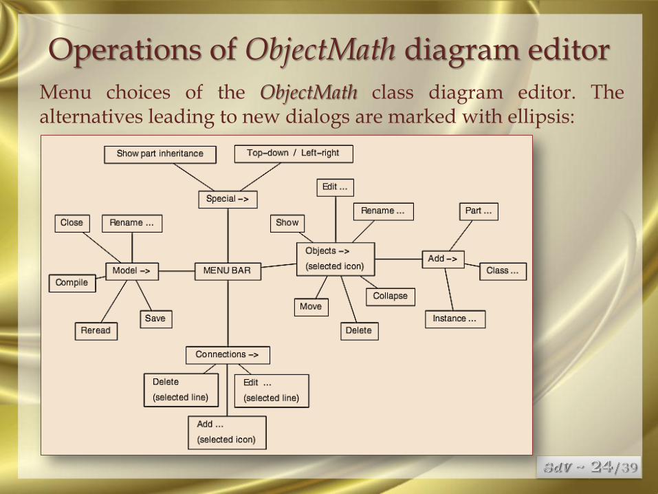
Menu choices of the ObjectMath class diagram editor. The alternatives leading to new dialogs are marked with ellipsis:
Operations of ObjectMath diagram editor

A Mathematica
notebook with
results of a
symbolic
integration, 2D
and 3D plots.
The notebook
cell structure is
made visible via
brackets on the
right side.
USING THE MATHEMATICA ENVIRONMENT FOR GENERATING EFFICIENT 3D GRAPHICS

The screen
shot of the
MAGGIE
tool with
animation
of a
parametric
surface:
… USING THE MATHEMATICA ENVIRONMENT FOR GENERATING EFFICIENT 3D GRAPHICS

Water surface after the stones
fell down and the waves
appeared. The stones are below the
surface and we look at them from below.
This is a screen shot from the
animation sequence.
… USING THE MATHEMATICA ENVIRONMENT FOR GENERATING EFFICIENT 3D GRAPHICS

Design optimization problem. For instance, the optimal size of the balls in bearings is searched in order to minimize friction. The function F simulates movement of some mechanism with a parameter vector x. The function E estimates how good the movement trajectory is. The goal of simulation series is to find such xm that E(F(xm)) achieves its maximum. The function E has many parameters. Therefore engineers use interactive environments and visual aids in order to find the appropriate xm. In applications for mechanical models it is very important to display forces, velocities and accelerations that occur in the simulated world. The simulation is not affected by the user after it starts, and usually the trajectories are analyzed after the results are computed.
Visualization Requirements Induced by Simulation Goals

Control system design. Assume that a robot that finds, grabs, moves and releases a detail should be designed. A control system for this robot should be developed. This control system should operate so that the robot performs the mission in minimum time and with maximum accuracy. The function E is an overall estimation of the quality of robot performance. A simulation function F for the robot includes Fm (a mechanical component) and Fc (a control component). The goal of the simulation is to find an algorithm Fc such that E(F(x)) is maximal. Visualization of such simulations should include display of trajectories of movements and comparison tools for such trajectories. A simulation can be affected by the user after it starts; in particular the user can feed different inputs (mission descriptions) to the control system. If the control system is designed so that it is able to compensate for errors in the movements of the machine elements, the numerical accuracy of computations can be reduced without excessively affecting the overall precision of the simulation.
… Visualization Requirements Induced by Simulation Goals

Simplification problem. Quite often there exists a numerical method to find f(x) which can be used as an approximation of F(x), i.e. f(x)≈F(x), and f(x) can be computed much faster. In particular, linearized results from finite element model computations are often used in order to reduce computation time. It is important to visualize the differences between F(x) and f(x), and to investigate (e.g. using interactive visualization) how these can be reduced.
… Visualization Requirements Induced by Simulation Goals
Presentation. Artistic, emotional and educational side effects of simulation, i.e. evaluation of F(x), is useful in many cases, such as computer games, movie industry, digital art, and human operator training. Numerical accuracy of computations can be reduced unless deviations between the simulated world and the real one can be perceived by the human during the simulation. However, color and texture choice is important in visualization. In order to use simulation interactively fast response time should be achieved. There is a trade-off between response speed, model complexity and accuracy.

Multibody Simulation Tools.
The purpose of multibody simulation tools is to perform
various kinds of static and dynamic analyses of mechanical
systems. Mechanical elements are fetched from libraries of
ready components and their position and orientation is
defined via a CAD-like 3-dimensional user interface. The
connections between the elements are set up interactively
using a CAD-like tool. Such tools are usually tightly coupled
with the simulation tool, and a uniform graphical user
interface and three-dimensional representation of mechanical
parts is used both at the modeling stage and during
visualization of simulation results.
… Visualization Requirements Induced by Simulation Goals

ADAMS. Adams is the world’s most widely used multibody mechanical simulation software. It can be used in different configurations: as a full simulation package (Adams/View, Adams/Solver and other components) or as Adams prototyping capabilities integrated within CAD/CAM environments.
… Visualization Requirements Induced by Simulation Goals
Cooperation
between
simulation
engineer,
Adams/View
and
Adams/Solver:

Four typical ADAMS statements:
… Visualization Requirements Induced by Simulation Goals

The notation provides a relatively high flexibility of Adams models. The same model can be used for three different kinds of simulations: Kinematic simulation: All motions are already prescribed by
the user. The system has zero degrees of freedom. All part positions can be computed from the motions. Forces are ignored.
Static simulation: This simulation re-positions parts so that all forces are balanced. It finds the so called equilibrium configuration.
Dynamic simulation: This simulation computes the combined effect of forces and constraints. It can be used for any number of degrees of freedom. The dynamic simulation package contains four different integrators. The user should tune these integrators by giving appropriate accuracy, integration step minimum and maximum, as well as other tuning parameters.
… Visualization Requirements Induced by Simulation Goals

Visualization. During simulation or after the simulation terminates (in Adams/Solver) the user can see dynamic visualizations of machine elements. Adams has a rich set of constructs helping to run a series of simulations as a batch. In the 3D visualization the results of two (or more) simulations can be displayed and compared.
… Visualization Requirements Induced by Simulation Goals
Cooperation
between a
simulation
engineer
(user), and
Adams plug-
in embedded
in a CAD
application.

Working Model 3D.
Integrated Environments for Computer-Based Animation (3D Studio Max)
… Visualization Requirements Induced by Simulation Goals
Double
pendulum
model
in
Working
Model
3D:

Working Model 3D.
Integrated Environments for Computer-Based Animation (3D Studio Max)
… Visualization Requirements Induced by Simulation Goals
A
pendulum
model
in
3D
Studio
Max:

Working Model 3D.
Integrated Environments for Computer-Based Animation (3D Studio Max)
… Visualization Requirements Induced by Simulation Goals
Hierarchy of
objects in
the model
of a
pendulum in
3D Studio
Max

References
1. Tools for Design, Interactive Simulation, and Visualization of Object-
Oriented Models in Scientific Computing, Vadim Engelson, Linköping
Studies in Science and Technology, Department of Computer and
Information Science, Linköpings universitet, SE-581 83 Linköping,
Sweden;
2. Automatic generation of user interfaces from data structure
specifications and object-oriented application models, Vadim Engelson,
Dag Fritzson and Peter Fritzson, Published in Proceedings of European
Conference on Object-Oriented Programming (ECOOP96), Linz, Austria,
8-12 July 1996, Pierre Cointe (ed.); Lecture Notes in Computer Science,
vol. 1098, Springer-Verlag, pp. 114-141.
3. Tools for Design, Interactive Simulation and Visualization for Dynamic
Analysis of Mechanical Models, Vadim Engelson, PELAB, IDA, Link¨
oping University.
4. 3D Systems, Stereo Lithography Interface Specification, 3D Systems,
Inc., Valencia, CA 91355. Available via
http://www.vr.clemson.edu/credo/rp.html.
5. ADAMS and Mechanical Dynamics Adams, ADAMS and Mechanical
Dynamics, Inc., http://www.adams.com
6. Advanced Visual Systems Inc., AVS/Express. http://www.avs.com


