+ All Categories
Home > Documents > Interchange Distribution Calculator Working Group Agendas... · Attendees1 Yasser Bahbaz, Chair SPP...

Interchange Distribution Calculator Working Group Agendas... · Attendees1 Yasser Bahbaz, Chair SPP...

Date post: 31-Jul-2018
Category:
Upload: vutram
View: 216 times
Download: 0 times
Share this document with a friend
54
Minutes Interchange Distribution Calculator Working Group October 16–17, 2012 Encore Las Vegas 3121 Las Vegas Blvd. South Las Vegas, Nevada The Interchange Distribution Calculator Working Group (IDCWG) met on October 16–17, 2012 in Las Vegas, Nevada. The meeting agenda is affixed as Exhibit A. Chair Yasser Bahbaz presided and Larry Kezele announced that a quorum was present. Attendees 1 Yasser Bahbaz, Chair SPP Hardeep Kandola IESO Mohamad Yassin OATI Hugh Francis* Southern Allan Watson, Vice Chair IESO Larry Kezele NERC Brian Strickland* ICTE David Mahlmann NYISO Marilyn Jayachandran* PJM Mike Colby* PJM Keith Mitchell MISO Ben Taylor TVA Cheryl Mendrala* ISO-NE Carlos Gonzalez-Perez OATI David Lemmons Xcel Energy Raja Thappetaobula MISO Paul Graves FRCC Frank Koza PJM Notice of Public Meeting and Antitrust Compliance Statement Mr. Kezele summarized the Notice of Public Meeting and the NERC Antitrust Compliance Guidelines. Interchange Distribution Calculator Working Group Meeting Minutes The IDCWG approved the minutes of the August 15–16, 2012 meeting (Motion 1) and the minutes of the September 24, 2012 conference call meeting (Motion 2). 1 * Indicates participation by speakerphone.
Transcript

Minutes Interchange Distribution Calculator Working Group October 16–17, 2012 Encore Las Vegas 3121 Las Vegas Blvd. South Las Vegas, Nevada

The Interchange Distribution Calculator Working Group (IDCWG) met on October 16–17, 2012 in Las Vegas, Nevada. The meeting agenda is affixed as Exhibit A. Chair Yasser Bahbaz presided and Larry Kezele announced that a quorum was present. Attendees1

Yasser Bahbaz, Chair

SPP Hardeep Kandola IESO Mohamad Yassin OATI Hugh Francis* Southern Allan Watson, Vice Chair IESO Larry Kezele NERC Brian Strickland* ICTE David Mahlmann NYISO Marilyn Jayachandran* PJM Mike Colby* PJM Keith Mitchell MISO Ben Taylor TVA Cheryl Mendrala* ISO-NE Carlos Gonzalez-Perez OATI David Lemmons Xcel Energy Raja Thappetaobula MISO Paul Graves FRCC Frank Koza PJM Notice of Public Meeting and Antitrust Compliance Statement Mr. Kezele summarized the Notice of Public Meeting and the NERC Antitrust Compliance Guidelines. Interchange Distribution Calculator Working Group Meeting Minutes The IDCWG approved the minutes of the August 15–16, 2012 meeting (Motion 1) and the minutes of the September 24, 2012 conference call meeting (Motion 2).

1 * Indicates participation by speakerphone.

erwinj
Typewritten Text

Interchange Distribution Calculator Working Group Meeting Minutes October 16–17, 2012

2

Future Meetings Meeting/Conf. Call Purpose Date

IDCWG Conference Call Review evaluation of CO-356 and draft IDC Data Requests change order

October 29, 2012 (10:00–11:00 a.m. EDT)

IDCWG Meeting Regular Meeting January 29, 2013 (8:00 a.m.– 5:00 p.m. PST) and January 30, 2013 (8:00 a.m.– 5:00 p.m. PDT) Redwood City, California, hosted by OATI

Review of Agenda Chair Bahbaz reviewed the agenda and prioritized agenda items. The working group will conduct closed sessions as required. IDCWG Roster The working group reviewed and revised the roster. IDCWG Self-directed Work Teams The working group reviewed membership of each of the self-directed work teams:

Project Management Yasser Bahbaz (Team Lead), Allan Watson, Larry Kezele

Market Flow Raja Thappetaobula (Team Lead), Yasser Bahbaz, LaChelle Brooks, Allan Watson, David Mahlmann, Larry Kezele

Documentation LaChelle Brooks (Team Lead), Allan Watson, Cheryl Mendrala, Ben Taylor, Hugh Francis, Wendy Ladd, Larry Kezele

NERC Update Chair Bahbaz reported that the Operating Reliability Subcommittee (ORS) met on September 11–12, 2012. Topics of interest to the working group include:

• Supported TVA RC’s request to implement an IDC change order that addresses IPPs within the TVA reliability coordinator area.

• Reviewed potential IDC requirements to implement the Parallel Flow Visualization project.

• Supported the working group’s investigation of the impact of the IDC model swing bus location on network/native load calculations.

Interchange Distribution Calculator Working Group Meeting Minutes October 16–17, 2012

3

• Discussed FERC Order 764 (Integration of Variable Energy Resources) and 15-minute interchange transaction scheduling. Larry Kezele reported that the Joint Electric Scheduling Subcommittee and the Interchange Subcommittee met by conference call on October 9, 2012 to discuss the implications of implementing the provisions of FERC Order 764. The JESS and IS focused on INT-007-1 (Interchange Confirmation), Requirement 1, and BAL-006-2 (Inadvertent Interchange), Requirement 4. The JESS will further discuss this topic at its October 31–November 1, 2012 meeting. The working group will further discuss if the implementation of CO-328 (Intra-Hour Curtailments) addresses the requirements of FERC Order 764.

NERC/NAESB Coordination Chair Bahbaz reported that the NAESB Business Practices Subcommittee and the IDCWG are meeting jointly on the afternoon of October 17, 2012. He reviewed the list of topics which the BPS would like to discuss with the working group:

• IDC transition to the RC Consortium

• Parallel Test – Development and implementation of change orders for the PFV Project Motions

Motion-1: Moved: David Mahlmann; Action: Passed. Approve the minutes of the August 15–16, 2012 IDCWG meeting.

Motion-2: Moved: David Mahlmann; Action: Passed. Approve the minutes of the September 24, 2012 IDCWG conference call meeting.

Motion-3: Moved: Vice Chair Watson; Action: Passed. Approve Version 2 of CO-350 (Increase the Initial Limit for NNL Relief Provided during TLR Issuance) for development.

Motion-4: Moved: Ben Taylor; Action: Passed. Approve CO-352 (Various Enhancements to the NNL Re-Dispatch Worksheet) for development.

Motion-5: Moved: Vice Chair Watson; Action: Passed. Approve CO-354 (Sending IDC TLR ID to SPP Via webData Interface) for development, contingent upon resolution of a contractual agreement between SPP and NERC regarding funding.

Motion-6: Moved: Raja Thappetaobula; Action: Passed. Approve CO-355 (Make Information Flowgates Selectable in Study TLR Mode) for development.

Motion-7: Moved: Ben Taylor; Action: Passed. Approve CO-356 (TVA RC requires all IPPs to be a Pseudo Balancing Authority in the IDC) for evaluation.

Interchange Distribution Calculator Working Group Meeting Minutes October 16–17, 2012

4

Motion-8: Moved: David Mahlmann; Action: Passed. Approve Version 0 of the IDC User’s Manual.

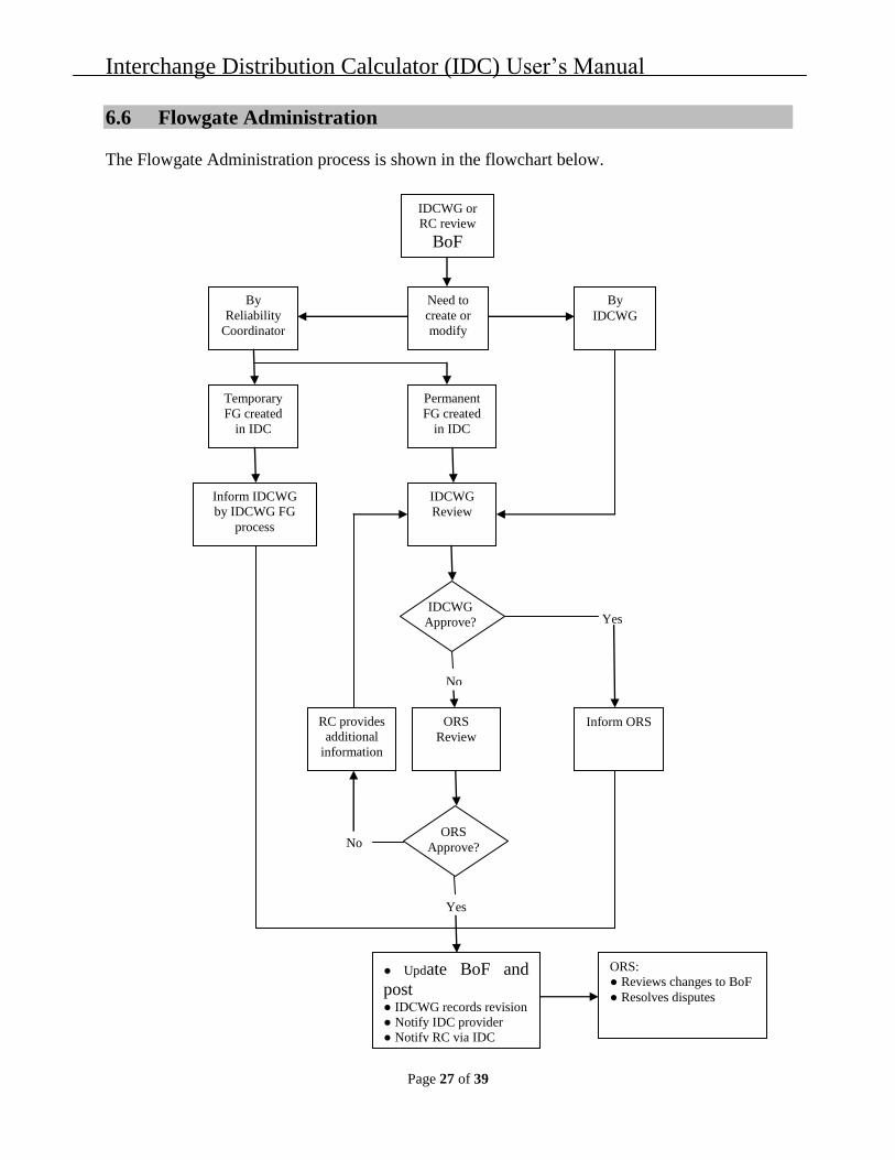
Motion-9: Moved: David Mahlmann; Action: Passed. Approve recommending to the ORS retirement of the Parallel Flow Calculation Procedures, the Flowgate Administration and the Reliability Coordinator Reference Documents. IDC Change Orders (CO)

1. CO-283 Generator-to-Load Reporting Requirements Further action related to CO-283 awaits the completion of the NAESB PFV business practices.

2. CO-322 Generation Priority Submission Chair Bahbaz reported that CO-322 will have to be redrafted based on the current version of the BPS PFV Permanent Solution white paper.

3. CO-326 Parallel Flow Visualization Metrics Chair Bahbaz explained the purpose of CO-326 which is:

As the parallel flow visualization (PFV) project prepares to enter the pilot period, more benchmarking tools are needed to compare the results in both current production IDC logic and the generator-to-load (GTL) calculation logic. The difference between the two logics in the two environments should be justifiable and defensible through the enhancements in visualization of parallel flows in the IDC. The following metrics assume that the methodology for PFV relief assignment has been determined and incorporated into the IDC.

CO-326 will have to be redrafted based on the final version of the BPS PFV Permanent Solution white paper.

4. CO-330 Authorization of OATI Use of IDC Data for DOE Studies Chair Bahbaz explained that OATI contracted with the DOE to perform studies that require use of data from the IDC. Any data provided to the DOE will be in a form which does not specifically identify confidential data taken from the IDC. It is expected that all data presented will be in the form of aggregates and statistical summaries. Carlos Gonzalez-Perez reviewed the development status of CO-330 at the working group’s December 2011 meeting.

The Department of Energy would like to have actual and scheduled flow information on specific Eastern Interconnection interfaces for 2010. OATI can, in most instances, derive the scheduled flow by using e-Tag information. However, deriving the actual flows on the interfaces and the scheduled flows on interfaces within a market is more problematic. OATI continues to gather IDC data to support the DOE Study.

Mohamad Yassin reported that DOE recently requested similar data for 2011 and that OATI would like to keep CO-330 open until the DOE study is completed. Chair Bahbaz expressed his opinion that OATI’s internal response to DOE’s request for 2011 data goes beyond the scope of CO-330. OATI has not yet provided the 2011 data to DOE. If DOE wants to receive 2011 data, a new IDC

Interchange Distribution Calculator Working Group Meeting Minutes October 16–17, 2012

5

change order should be drafted and submitted to the working group for its consideration. Chair Bahbaz will discuss the provision of 2011 data to DOE with the ORS at its November 2012 meeting.

5. CO-336 Changes to IDC Factor Calculation Timing Chair Bahbaz explained that when the regulation status of the Michigan-Ontario PARS is manually changed within the IDC, a factor calculation should be manually initiated. It is understood that if the calculation is already in progress the manual initiation will be started upon completion. This will allow the IDC to effect a change in the TLR process factor calculation within approximately five to eight minutes of the regulation status change of the Michigan-Ontario PARS depending on the status of the current calculation. The “Active TLR” or Main IDC display will indicate that a manual calculation has been completed due to the PARS status change. Currently the only PARS modeled in the IDC are the Michigan - Ontario PARS. However, CO-336 would also apply to all future PARS.

The working group approved CO-336 for development at its December 2011 meeting. OATI anticipates that development of CO-336 will take approximately one month; hence, NERC will not sign the change order until requested to do so by MISO and/or IESO. Vice Chair Watson reported that there is no change in status for this change order.

6. CO-350 Increase the Initial Limit for NNL Relief Provided During TLR Issuance Mohamad Yassin reviewed the evaluation of Version 2 of IDC CO-350 and explained that the current maximum limit for system operator entry of NNL relief provided during TLR issuance is five hundred (500) MW. Version 2 of CO-350 requires an acknowledgment of an NNL relief value above 500 MW and removes the 999 MW NNL limit. Vice Chair Watson moved to approve Version 2 of CO-350 for development (Motion 3). The working group approved the motion.

7. CO-351 Update the Flowgate GLDF Display to Show PJM Historic Control Areas Chair Bahbaz explained that currently, the IDC Flowgate GLDF Display shows PJM marginal zones for the GLDF, GSF, and LSF for a particular flowgate. PJM would like to use the generator mappings from the Book of Flowgates to map the generators for the GLDF, GSF, and LSF to their historic Control Area level instead of the PJM Marginal Zone. The factors calculation should change to calculate the additional factors for the historical PJM Control Areas (AEP, CE, DEOK, DLCO, DPL, FE, PJM, and VAP). This display should be able to support any new Control Areas entering PJM. At its September 24, 2012 conference call meeting the working group moved approved CO-351 for development, contingent upon resolution of a contractual agreement between PJM and NERC regarding funding. Larry Kezele reported that PJM and NERC have not yet entered into a contractual agreement.

8. CO-352 Various Enhancements to the NNL Re-Dispatch Worksheet Chair Bahbaz reviewed the evaluation of CO-352 and explained that there is currently no way to use INC only or DEC only combinations. Therefore, implementation of CO-352 would add a NO GEN selection with a 0% GLDF in each column. This would recognize the possibilities to DEC only and replace with imported power or to INC only and replace with exported power using bilateral agreement transactions. To ensure the balancing authority properly accounts for the path impact

Interchange Distribution Calculator Working Group Meeting Minutes October 16–17, 2012

6

make the import path TDF available in the INC column and the export path TDF available in the DEC column. More specifically, the NNL re-dispatch worksheet will only include generators in the balancing authority email that were re-dispatched in the worksheet. In order to provide all this information to the balancing authorities without IDC access, provide an email button next to the source point in the congestion management report to email the entire INC/DEC list to the balancing authority. This list should also include available source/sink TDFs (i.e., individual TDF not source-to-sink combinations). Ben Taylor moved to approve CO-352 for development (Motion 4). The working group approved the motion.

9. CO-353 PSEC-SOCO Dynamic Tags Chair Bahbaz reviewed the evaluation of CO-353 and explained that Power South Energy Cooperative (PSEC) is registered as a BA, DP, GO, GOP, IA, LSE, PA, PSE, RP, TO, TP, and TOP. PSEC is located in the SERC Southeastern Sub-region Reliability Area. The PSEC load has two components. About 55 percent of the load is located inside the boundaries of their balancing authority. The remaining 45 percent of the load is located inside the Southern balancing authority area in Alabama and Florida. The total load is sent to the IDC through SDX. The load inside the Southern balancing authority is served by two dynamic tags. The result is that the PSEC load in the Southern balancing authority gets curtailed by the tag and curtailed through NNL during a TLR-5. Implementation of CO-353 would exempt tags that have a source of AEC, a sink of SOCO, and contain either AECB01ALA or AECB01FLA in the tag name from TLR curtailment. Hugh Francis stated that Southern is not ready to move forward with development of CO-353. The working group will further review CO-353 at its January 2013 meeting.

10. CO-354 Sending IDC TLR ID to SPP Via webData Interface Chair Bahbaz reviewed the evaluation of CO-354 and explained that currently Southwest Power Pool (SPP) receives all data related to TLRs active within the IDC. The SPP Market System needs the TLR data to ensure it provided any relief obligation the SPP Market may have on any SPP Market coordinated flowgate. To identify any newly issued TLRs that need SPP action, the SPP Systems sort though TLR messages sent by the IDC by flowgate number, effective dates and TLR level. The IDC assigns a unique TLR ID for every new TLR issuance or a TLR re-issuance. Since SPP is in the midst of redesigning its Market Systems and interfaces, it was decided by SPP staff that it is more efficient to sort through TLR messages sent to the Market System using the unique TLR ID. Therefore, SPP requests that the TLR ID, both action and event IDs be added to the messages from IDC to SPP via the webData interface. This change will only be applied to messages sent to SPP. Vice Chair Watson moved to approve CO-354 for development, contingent upon resolution of a contractual agreement between SPP and NERC regarding funding (Motion 5). The working group approved the motion.

11. CO-355 Make Informational Flowgates Selectable in Study TLR Mode Chair Bahbaz reviewed the evaluation of CO-355 and explained that currently a study TLR cannot be run on an Informational Flowgate. Implementation of CO-355 would make informational flowgates available in Study TLR mode and would provide a pop-up window to remind the operator

Interchange Distribution Calculator Working Group Meeting Minutes October 16–17, 2012

7

that “This flowgate is an Informational Flowgate only.” Since TLR cannot be issued on informational flowgates, a temporary flowgate representing the definition of the informational flowgate may need to be built if TLR is needed. Raja Thappetaobula moved to approve CO-355 for development (Motion 6). The working group approved the motion.

12. CO-356 TVA RC requires all IPPs to be a Pseudo Balancing Authority in the IDC Chair Bahbaz reviewed a draft of CO-356, which highlights a known issue with the IDC where the impacts of IPPs within a balancing authority are ignored if they are sinking within the balancing authority in which they reside since it is seen as a balancing authority serving its own load. To address this the TVA RC is requiring all IPPs in their footprint, without a power purchase agreement of 2 years or longer with the balancing authority in which they reside, be represented as a pseudo balancing authority in the IDC in order to properly identify their impacts. TVA is also requesting that this change be made as a base case change to represent the generation of each IPP and a corresponding code change to map tags with specified generators as the source to those pseudo balancing authority area in the base case. This implementation would make it possible to keep the naming up-to-date easier for operator reference as IPP ownership may change. Ben Taylor moved to approve CO-356 for evaluation (Motion 7). The working group approved the motion.

SDX Change Orders (CO) There were no webSDX change orders to consider. WebFactor Change Orders (CO) There were no webFactor change orders to consider. NERC IT Services Change Orders (CO) There were no NERC IT Services change orders to consider. Book of Flowgates Change Orders (CO)

1. CO-16 PSSE Version Change Chair Bahbaz explained that implementation of the CO-16 modifies the BOF PSSE base case file import process to account for file format changes introduced in PSSE version 32. The changes in Version 32 are in the format of the RAWD file and will not impact the structure of the actual data. The working group decided to continue developing IDC base cases using PSSE version 30, since a PSSE version 32 base case can be easily converted into a version 30 base case for use in the IDC. Therefore, the working group decided that the IDC winter base case will be developed using PSSE version 30. The working group considered developing the 2013 IDC summer base case using version 32. CO-16 will remain on hold until the working group’s next meeting.

In addition, Hardeep Kandola reported that PSSE Version 33 is now available and asked if BOF CO-16 should be redrafted to reflect creation of the IDC base cases in Version 33. He also reported that, while the MMWG is not yet creating its base cases in Version 33, it plans to transition to

Interchange Distribution Calculator Working Group Meeting Minutes October 16–17, 2012

8

Version 33 in the near future. The working group decided to proceed with the development of CO-16 as written.

Calendar of Change Order Implementation and Other Related Events

1. August 1, 2012 – IDC Summer Model Update

2. September 5, 2012 – IDC Summer Model Update

3. October 2, 2012

• IDC Summer Model Update

• CO-328 (Intra-Hour Tag Curtailments) implemented

4. November 1, 2012 – IDC Winter Model Upload

5. December 1, 2012 – IDC Winter Model Update

6. January 3, 2013 – IDC Winter Model Update

7. February 1, 2013 – IDC Winter Model Update

8. March 1, 2013 – IDC Winter Model Update

9. April 3, 2013 – IDC Winter Model Update IDCWG Closed Session In closed session, Frank Koza briefed the working group on the transition of the IDC and other reliability software applications to an industry led management group. IDC Operations and Maintenance

1. IDC and SDX User Comments

a. None

2. IDC Event/Incident Reports — Mohamad Yassin reviewed IDC and webSDX help desk calls since the working group’s August 15–16, 2012 meeting. Mr. Yassin highlighted a problem report related to the calculation of GSF and TDF matrices. OATI traced this issue to a RAM overload caused by the number of flowgates for which the matrices need to be calculated. As a stop gap measure, OATI increased the available RAM to the maximum extent possible and restarted the calculation process. In total, the matrices were not being calculated for approximately one hour. The working group decided to perform an analysis of the temporary flowgates currently in the Book of Flowgates to determine if any can be eliminated. The working group will further discuss this topic at its next meeting.

Mr. Yassin also discussed a network outage of its Internet provider that led to an outage of OATInet, which impacted some OATI e-tag customers and market flow imports into the IDC by

Interchange Distribution Calculator Working Group Meeting Minutes October 16–17, 2012

9

some markets. Even though OATInet is a fully redundant fiber network, both fiber circuits were cut at different locations.

New Projects, Issues, and Other IDC/webSDX Matters

1. WebSDX Documentation The working group noted that when the NAESB BPS GTL business practices are finalized, the implementation of IDC CO-322 may require a change to the Balancing Authority webSDX User Guide for Providing Generator Outputs and the webSDX User Administrator Registration Guide.

2. IDC Access to e-Tag Data Cheryl Mendrala inquired as to how the IDC currently gathers e-Tag data. Mohamad Yassin that those e-Tags for which OATI is the tag vendor are automatically uploaded to the IDC. Carlos Gonzalez-Perez reported that for e-Tags that are created by other tag vendors, those tags are uploaded to the IDC through use of the reliability coordinator forwarding URL on the tag.

3. WebRegistry Status Report Mr. Gonzalez-Perez briefed the working group on the current status of the transition from the NERC TSIN to the NAESB Electric Industry Registry (commonly referred to as webRegistry). Beginning on November 6, 2012, TSIN and webRegistry will be frozen for one week to allow for final data validation. WebRegistry is scheduled to replace TSIN on November 13, 2012.

Mr. Gonzalez-Perez discussed the mappings that currently exist in the IDC and/or TSIN that need to be accurately mapped to webRegistry. OATI will be providing the working group with a list of information that is in TSIN that is not yet in webRegistry, especially POR/PODs.

4. Implementation of IDC CO-328 (Intra-Hour Tag Curtailments) Chair Bahbaz discussed an example of how the implementation of CO-328 may be impacted by 15-minute scheduling as outlined in FERC Order 764. Cheryl Mendrala, on behalf of the working group, will brief the JESS and the IS on the FERC Order’s possible implications to current IDC TLR processes.

5. PSSE Bus Numbering Chair Bahbaz informed the working group that SPP submitted data for a “fictitious” bus and MISO submitted bus data for the same bus. However, MISO’s data submittal overwrote the data submitted by SPP, resulting in an erroneous network model being uploaded to the IDC. The working group decided to allocate specific bus ranges to specific reliability coordinators for their use when needing to submit data related to a “fictitious” bus. IESO will investigate if a validation check could be performed to determine if the base case contains any tie-lines that were not formerly in the IDC model.

6. SPP Integrated Market Place Testing Chair Bahbaz explained that SPP is targeting startup of its integrated market in March 2014. At that point the SPP market balancing authorities will become a single SPP market balancing authority much like the MISO market balancing authority. SPP will be conducting testing on the IDC development system and will coordinate this testing with reliability coordinators.

Interchange Distribution Calculator Working Group Meeting Minutes October 16–17, 2012

10

7. Entergy Transition to MISO Raja Thappetaobula informed the working group that Entergy is currently scheduled to transition to the MISO reliability area on December 1, 2012. The working group changed the date of the December IDC model update to December 1, 2012 to reflect this transition. Mohamad Yassin suggested that an IDC change order is not required to facilitate that transition; however, updates are required to webRegistry. In addition, webSDX will automatically change as the Entergy transition is reflected in the Book of Flowgates.

8. IDC Reference Document Hugh Francis reviewed Version 0 of the IDC Reference Document. The working group amended one section of the document and decided to change the document’s title to IDC User’s Manual. Mr. Francis will also change DFWG to IDCWG and RCWG to ORS. David Mahlmann moved to approve Version 0 of the IDC User’s Manual (Exhibit B), (Motion 8). The working group approved the motion.

David Mahlmann moved to approve recommending to the ORS retirement of the Parallel Flow Calculation Procedures, the Flowgate Administration and the Reliability Coordinator Reference Documents (Motion 9). The working group approved the motion. The three reference documents are being replaced by the SDX User’s Manual and the IDC User’s Manual.

9. Location of IDC Model Swing Bus The working group continued its discussion of the impact of the location of the IDC model system swing bus on calculation of GLDFs. Raja Thappetaobula reported that he and Paul Graves analyzed the impact of moving the swing bus to Turkey Point in south Florida on the TDFs and GSFs of 14 flowgates. Mr. Thappetaobula reported there was not any change in the generator to generator impacts; however, there was some minor changes in the GLDFs, especially for those non-load serving balancing authorities. The working group recognized the need to clarification some of the IDC training documents currently posted on the working group’s web site. Chair Bahbaz tasked the Documentation SDWT to clarify the training documents and suggested that the working group further discuss this topic at its next meeting.

10. IDC Data Requests —Raja Thappetaobula drafted a change order related to automated congestion management reports that would allow reliability coordinators to download TLR event data from the IDC for use in compliance audits. The working group discussed using CO-349 as a starting point for a generic IDC data request change order. The working work also discussed adding a market flow report to the change order. Based on the working group’s discussion, Mr. Thappetaobula will redraft the change order for discussion at a future meeting.

Adjournment The meeting was adjourned at 11:30 p.m. PDT on October 17, 2012.

Larry Kezele Larry Kezele Secretary

Agenda Interchange Distribution Calculator Working Group October 16, 2012 | 8:00 a.m.–5:00 p.m. PT October 17, 2012 | 8:00 a.m.–Noon p.m. PT Encore Las Vegas 3121 Las Vegas Blvd. South Las Vegas, Nevada 702.770.7000 Conference: 1-866-740-1260; Passcode: 5247004; Security Code: 214110 Introductions and Chair’s Remarks NERC Antitrust Compliance Guidelines and Public Announcement Agenda

1. Administrative Matters

a. Arrangements – Larry Kezele

b. Announcement of Quorum – Larry Kezele

c. Parliamentary Procedures* – Larry Kezele

d. Approve Agenda – Chair Bahbaz

Closed sessions will be conducted as required.

e. Future Meetings and Conference Calls – Chair Bahbaz

i. Schedule future meetings

Exhibit A

erwinj
Typewritten Text

IDCWG Meeting October 16–17, 2012

2

f. Approval of the IDCWG Meeting Minutes* – Chair Bahbaz

i. August 15–16, 2012 IDCWG Meeting Minutes

ii. September 24, 2012 IDCWG Conference Call Meeting Minutes

g. NERC feedback from Operating Reliability Subcommittee (ORS) – Larry Kezele

The ORS met on September 11–12, 2012. Topics of interest to the working group include:

i. Supported TVA RC’s request to implement an IDC change order that addresses IPPs within the TVA reliability coordinator area.

ii. Reviewed potential IDC requirements to implement the Parallel Flow Visualization project.

iii. Supported the working group’s investigation of the impact of the IDC model swing bus location on network/native load calculations.

iv. Discussed FERC Order 764 (Integration of Variable Energy Resources) and 15-minute transaction scheduling.

h. North American Electric Reliability Corporation/North American Energy Standards Board (NERC/NAESB) coordination update

i. Business Practices Subcommittee – Ed Skiba or Narinder Saini

ii. The IDCWG and the NAESB BPS will meet jointly on October 17, 2012 from 1 p.m. to 5 p.m. PDT

i. Review IDCWG roster* – Larry Kezele

j. Review membership of the IDC self-directed work teams – Chair Bahbaz

Project Management Yasser Bahbaz (Team Lead), Allan Watson, Larry Kezele

Market Flow Raja Thappetaobula (Team Lead), LaChelle Brooks, Yasser Bahbaz, Allan Watson, David Mahlmann, Larry Kezele

Documentation LaChelle Brooks (Team Lead), Cheryl Mendrala, Ben Taylor, Hugh Francis, Wendy Ladd, Allan Watson, Larry Kezele

IDCWG Meeting October 16–17, 2012

3

2. Review of Active Interchange Distribution Calculator (IDC) Change Orders (CO) (Secretary’s Note: The IDC Change Orders for discussion at this meeting are posted in a zip file on the IDCWG web site.)

a. CO-283: Generator-to-Load Reporting Requirement (Status — Accepted as implemented on November 1, 2010) Action:

i. Review outstanding variances and other areas of development

ii. Status of data transmittals

b. CO-322: Generation Priority Submission (Status —Version 2 approved for evaluation) Action: Review evaluation and approve for development.

c. CO-326: Parallel Flow Visualization Metrics (Status — Review draft) Action: Approve for evaluation.

d. CO-330: Authorization of OATI Use of IDC Data for DOE Studies (Status — Approved for development) Action: NERC approved for development, review status of development.

e. CO-336: Changes to IDC Factor Calculation Timing (Status — Approved for development) Action: Review status of development.

f. CO-350: Increase the Initial Limit for NNL Relief Provided During TLR Issuance (Status — Version 2 evaluated) Action: Approve for development.

g. CO-351: Update the Flowgate GLDF Display to Show PJM Historic Control Areas (Status — Approved for development, contingent upon resolution of a contractual agreement between NERC and PJM regarding funding) Action: NERC and PJM have not yet entered into a contractual agreement regarding funding.

h. CO-352: Various Enhancements to the NNL Re-Dispatch Worksheet (Status — Evaluated) Action: Review evaluation and approve for development.

i. CO-353: TLR Acknowledgement/Curtailment Archival (Status — Evaluated) Action: Review evaluation and approve for development.

IDCWG Meeting October 16–17, 2012

4

j. CO-354: Sending IDC ID to SPP Via webData Interface (Status — Evaluated) Action: Review evaluation and approve for development, contingent upon resolution of a contractual agreement between NERC and SPP regarding funding.

k. CO-355: Make Informational Flowgates Selectable in Study TLR Mode (Status — Evaluated) Action: Review evaluation and approve for development.

3. Review of Active webSDX (SDX) Change Orders (CO) (Secretary’s Note: The webSDX Change Orders for discussion at this meeting are posted in a zip file on the IDCWG web site.) There are no webSDX change orders to review at this meeting.

4. Review of Active webFactor (Factor Viewer) Change Orders (CO)

(Secretary’s Note: The Factor Viewer Change Orders for discussion at this meeting are posted in a zip file on the IDCWG web site.) There are no webFactor change orders to review at this meeting.

5. Review of Active NERC IT Services Change Orders (CO) (Secretary’s Note: The NERC IT Services Change Orders for discussion at this meeting are posted in a zip file on the IDCWG web site.) There are no NERC IT Services change orders to review at this meeting.

6. Review of Active Book of Flowgates Change Orders (CO)

(Secretary’s Note: The Book of Flowgates Change Orders for discussion at this meeting are posted in a zip file on the IDCWG web site.)

a. CO-16: PSSE Version Change (Status —Evaluated) Action: Review evaluation and approve for development.

7. IDCWG Calendar of Change Order Implementation and Other IDC-Related Events

a. August 1, 2012 – IDC Summer Model Update

b. September 5, 2012 – IDC Summer Model Update

c. October 2, 2012

i. IDC Summer Model Update

ii. CO-328 (Intra-Hour Tag Curtailments) implemented

d. November 1, 2012 – IDC Winter Model Upload

IDCWG Meeting October 16–17, 2012

5

e. December 4, 2012 – IDC Winter Model Update

f. January 3, 2013 – IDC Winter Model Update

g. February 1, 2013 – IDC Winter Model Update

h. March 1, 2013 – IDC Winter Model Update

i. April 3, 2013 – IDC Winter Model Update

j. May 1, 2013 – IDC Summer Model Upload 8. IDCWG Maintenance

a. IDC operation:

b. Event/incident reports – OATI

i. Review Help Desk calls 9. New Projects, Issues, Other

a. WebSDX Documentation

i. The working group will review Version 1.0 of the Balancing Authority webSDX User Guide for Providing Generator Outputs and Priority and Version 2.3 of the webSDX User Administrator Registration Guide to determine if these documents require revision to support implementation of IDC CO-322.

b. IDC User’s Manual Hugh Francis will review, for working group approval, the IDC User’s Manual.

c. Location of IDC Model Swing Bus The working group will continue its discussion of the impact of the location of the IDC model system swing bus on calculation of GLDFs.

d. IDC Data Requests Vice Chair Watson and Raja Thappetaobula will report on their efforts to develop a proposal that will allow IDC users increased functionality to query the IDC.

* Background materials attached.

Interchange Distribution Calculator (IDC)

User’s Manual

Version 0

Exhibit B

erwinj
Typewritten Text

Interchange Distribution Calculator (IDC) User’s Manual

Page 2 of 39

Table of Contents 1.0 Record of Revisions ............................................................................................................. 4

2.0 General Information ............................................................................................................. 5

2.1 NERC Reliability Standards............................................................................................. 5

2.2 IDC Provider and 24x7 Technical Support ...................................................................... 5

3.0 Transmission Loading Relief Levels ................................................................................... 5

3.1 TLR Levels ....................................................................................................................... 6

3.2 TLR Level 6 ..................................................................................................................... 7

3.3 TLR Matrix ...................................................................................................................... 9

3.4 TLR Sub-Priorities ......................................................................................................... 10

3.5 TLR Reallocation ........................................................................................................... 11

4.0 IDC Factors ........................................................................................................................ 11

4.1 Introduction .................................................................................................................... 11

4.2 Transmission Distribution Factor (TDF)........................................................................ 11

4.3 Generation Shift Factor (GSF) ....................................................................................... 12

4.4 Load Shift Factor (LSF) ................................................................................................. 12

4.5 Generation-to-Load Distribution Factor (GLDF) .......................................................... 13

4.6 How are GSF, TDF, LSF, and GLDF Calculated in the IDC? ...................................... 13

4.7 Generation Ownership Factors ....................................................................................... 15

4.8 Line Outage Distribution Factor (LODF) ...................................................................... 15

4.9 PTDF & OTDF Flowgates ............................................................................................. 15

5.0 Parallel Flow Calculation Procedure ................................................................................. 15

5.1 Introduction .................................................................................................................... 15

5.2 Basic Principles .............................................................................................................. 16

5.3 Calculation Method ........................................................................................................ 17

5.4 Calculation Procedure .................................................................................................... 18

5.5 Sample Calculation ........................................................................................................ 19

6.0 Flowgate Administration ................................................................................................... 22

6.1 General ........................................................................................................................... 22

6.2 Guidelines for Permanent Flowgates ............................................................................. 25

6.3 Guidelines for Temporary Flowgates ............................................................................. 25

6.4 Guidelines for Informational Flowgates ........................................................................ 25

6.5 IDCWG Flowgate Review ............................................................................................. 25

Interchange Distribution Calculator (IDC) User’s Manual

Page 3 of 39

6.6 Flowgate Administration ................................................................................................ 27

7.0 Market Guidelines for the IDC .......................................................................................... 28

7.1 General ........................................................................................................................... 28

7.2 Market Data Inputs ......................................................................................................... 28

7.3 Market Impacts on Flowgates ........................................................................................ 30

7.4 Market TDF Calculations ............................................................................................... 31

7.5 Tag Mapping to Marginal Zones .................................................................................... 31

7.6 Marginal Zone Participation Factors .............................................................................. 32

7.7 Market Pseudo Balancing Areas .................................................................................... 33

7.8 Market Flows.................................................................................................................. 33

7.9 TLR Notifications .......................................................................................................... 33

7.10 Market Relief Responsibility ...................................................................................... 34

7.11 Firm Re-dispatch Credits ............................................................................................ 34

7.12 Market Tag Dump Data .............................................................................................. 35

8.0 Phase Shifters in the IDC ................................................................................................... 35

8.1 Setup and Use of Phase Shifters in IDC ......................................................................... 35

8.2 Modeling Requirements for Phase Shifters .................................................................... 36

8.3 Submittal of e-tags over Phase Shifters.......................................................................... 36

8.4 IDC Use of Phase Shifters in Regulate Mode ................................................................ 37

8.5 IDC Use of Phase Shifters in Non-Regulate Mode ........................................................ 37

8.6 IDC Use of Phase Shifters in Bypass Mode ................................................................... 37

9.0 DC Ties in the IDC ............................................................................................................ 38

9.1 Modeling Requirements for DC Ties ............................................................................. 38

9.2 Submittal of e-tags over DC Ties ................................................................................... 38

9.3 DC Ties IDC Responsibility .......................................................................................... 38

10.0 NERC Tag Dump ............................................................................................................... 38

10.1 NERC Tag Dump Data Format .................................................................................. 38

Interchange Distribution Calculator (IDC) User’s Manual

Page 4 of 39

1.0 Record of Revisions

Revision Number

Date Effective

Description

0 2/27/2012 Created from a collection of existing documents

Interchange Distribution Calculator (IDC) User’s Manual

Page 5 of 39

2.0 General Information

2.1 NERC Reliability Standards The purpose statement of NERC Reliability Standard IRO-006-5 states that, “To ensure

coordinated action between Interconnections when implementing Interconnection-wide

transmission loading relief procedures to prevent or manage potential or actual SOL and IROL

exceedances to maintain reliability of the bulk electric system.” This coordinated action, for the

Eastern Interconnection, is obtained through the Interchange Distribution Calculator (IDC).

The Transmission Loading Relief Procedure used by the Reliability Coordinators in the Eastern

Interconnection is described in NERC Reliability Standard IRO-006-EAST-1.

2.2 IDC Provider and 24x7 Technical Support The IDC program is provided to the Eastern Interconnection by OATI. NERC administers user access.

OATI provides 24x7 support of the IDC system. During normal business hours, the OATI help

desk will be available to answer calls and provide basic system support. During off-hours all

calls to the help desk will be directed to the OATI answering service where calls will be

followed up and trouble tickets will be escalated to the appropriate line of support. Please contact

a NERC System Administrator for assistance in registration matters.

Email: [email protected]

Phone: 763-201-2010

FAX: 763-553-2813

3.0 Transmission Loading Relief Levels

The Interchange Distribution Calculator (IDC) uses TLR levels to define the severity of the

loading on the transmission system as well as actions that will be taken by the IDC to relieve the

overloading. TLRs are issued in levels from 0-6. TLR levels 3 and 5 are also sub-divided as a or

b. These subdivisions define the timing for the start of the TLR.

The NERC Transmission Loading Relief (TLR) procedure utilizes a Pro-Rata curtailment

method for all of the TLR Levels that require MW curtailment. For the Curtailment/Reallocation

calculations during TLR Level 3a, Non-Firm Priority transactions (1NS through 6NN) are

assigned sub-priorities within each individual priority bucket in order to make the curtailment of

Non-Firm transactions more efficient. When the transactions have been assigned to their Service

Priority Bucket each tag is then analyzed a second time to give them a Sub-Priority within their

associated Service Priority bucket such that when it is time to curtail in this bucket the MWs are

curtailed utilizing these priorities.

The Market Flow MWs for a coordinated flowgate (CF) are assigned in three priority levels, ED-

2, ED-6, and ED-7. For the Non-Firm priorities, ED-2 and ED-6, the Market Flow MWs are also

Interchange Distribution Calculator (IDC) User’s Manual

Page 6 of 39

given Sub-priority assignments so that Market Flow can be curtailed along with the transactions

in an equitable manner.

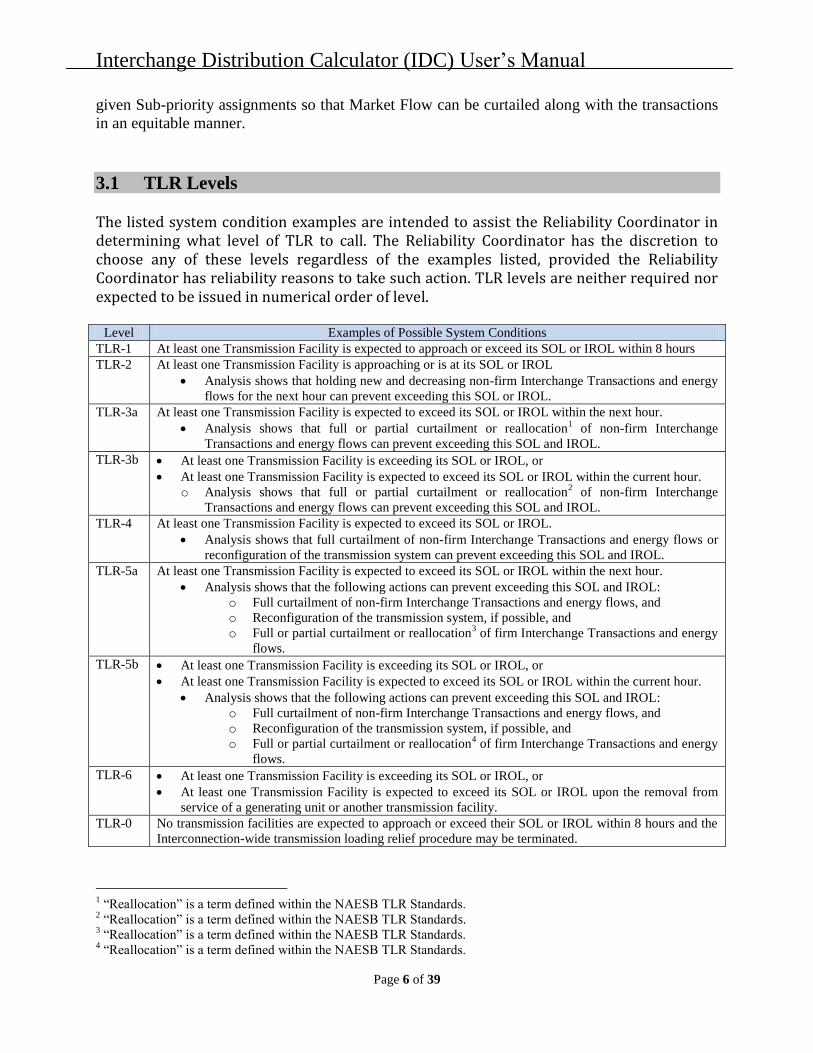
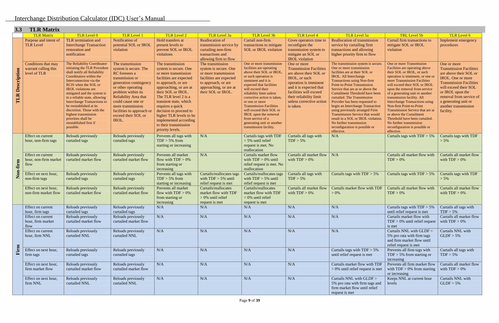
3.1 TLR Levels The listed system condition examples are intended to assist the Reliability Coordinator in determining what level of TLR to call. The Reliability Coordinator has the discretion to choose any of these levels regardless of the examples listed, provided the Reliability Coordinator has reliability reasons to take such action. TLR levels are neither required nor expected to be issued in numerical order of level.

Level Examples of Possible System Conditions

TLR-1 At least one Transmission Facility is expected to approach or exceed its SOL or IROL within 8 hours

TLR-2 At least one Transmission Facility is approaching or is at its SOL or IROL

Analysis shows that holding new and decreasing non-firm Interchange Transactions and energy

flows for the next hour can prevent exceeding this SOL or IROL.

TLR-3a At least one Transmission Facility is expected to exceed its SOL or IROL within the next hour.

Analysis shows that full or partial curtailment or reallocation1 of non-firm Interchange

Transactions and energy flows can prevent exceeding this SOL and IROL.

TLR-3b At least one Transmission Facility is exceeding its SOL or IROL, or

At least one Transmission Facility is expected to exceed its SOL or IROL within the current hour.

o Analysis shows that full or partial curtailment or reallocation2 of non-firm Interchange

Transactions and energy flows can prevent exceeding this SOL and IROL.

TLR-4 At least one Transmission Facility is expected to exceed its SOL or IROL.

Analysis shows that full curtailment of non-firm Interchange Transactions and energy flows or

reconfiguration of the transmission system can prevent exceeding this SOL and IROL.

TLR-5a At least one Transmission Facility is expected to exceed its SOL or IROL within the next hour.

Analysis shows that the following actions can prevent exceeding this SOL and IROL:

o Full curtailment of non-firm Interchange Transactions and energy flows, and

o Reconfiguration of the transmission system, if possible, and

o Full or partial curtailment or reallocation3 of firm Interchange Transactions and energy

flows.

TLR-5b At least one Transmission Facility is exceeding its SOL or IROL, or

At least one Transmission Facility is expected to exceed its SOL or IROL within the current hour.

Analysis shows that the following actions can prevent exceeding this SOL and IROL:

o Full curtailment of non-firm Interchange Transactions and energy flows, and

o Reconfiguration of the transmission system, if possible, and

o Full or partial curtailment or reallocation4 of firm Interchange Transactions and energy

flows.

TLR-6 At least one Transmission Facility is exceeding its SOL or IROL, or

At least one Transmission Facility is expected to exceed its SOL or IROL upon the removal from

service of a generating unit or another transmission facility.

TLR-0 No transmission facilities are expected to approach or exceed their SOL or IROL within 8 hours and the

Interconnection-wide transmission loading relief procedure may be terminated.

1 “Reallocation” is a term defined within the NAESB TLR Standards.

2 “Reallocation” is a term defined within the NAESB TLR Standards.

3 “Reallocation” is a term defined within the NAESB TLR Standards.

4 “Reallocation” is a term defined within the NAESB TLR Standards.

Interchange Distribution Calculator (IDC) User’s Manual

Page 7 of 39

3.2 TLR Level 6

This section describes the functionality that currently exists and options that the reliability

coordinator has when declaring TLR Level 6. This will help ensure the correct action is taken for

the given event.

IDC Treatment of TLR Level 6

When a reliability coordinator issues a TLR Level 6 on a flowgate in the IDC the application will

search the non-firm and firm e-tags that are in the IDC database for those that affect the flowgate

greater than or equal to 5%. It will create two sets of e-tags from this list for the reliability

coordinator to curtail:

1. If the e-tag has an active MW amount in the current hour it will be curtailed to zero MW.

2. If the e-tag is planned to start the next hour it will not be allowed to start and will be

curtailed to zero for the next hour.

Once this report is created and displayed as the congestion management report, the reliability

coordinator will then have three options to move forward with the TLR Level 6:

1. Confirm the curtailment list that contains the non-firm and firm complete

curtailments for the current and next hour.

1.1. This will alert the other reliability coordinators that a TLR Level 6 has been

declared and that there are curtailments that need to be acknowledged for

implementation.

1.2. Once the sinking reliability coordinators acknowledge the curtailments, the IDC

will send a reliability cap of zero MW to the balancing authorities on the e-tags

for curtailment implementation.

2. Exclude some or all of the e-tag curtailments from the IDC congestion management

report before declaring a TLR Level 6.

2.1. This can be done by the issuing reliability coordinator using the “Re-

issue/Exclude” option in the congestion management report.

2.2. This will give the issuing reliability coordinator the option of selecting those

transactions they wish to exclude from the TLR issuance.

2.3. Once the appropriate e-tags are selected the reliability coordinator will re-issue

the TLR and the list of excluded e-tags will appear on the congestion management

report but will not be in the curtailed state. The reliability coordinator will then

have to confirm the TLR to send the TLR Level 6 notification to the other

reliability coordinators.

2.4. Any e-tags that were not chosen for exclusion will be sent out to the other

reliability coordinators for acknowledgement and curtailment.

2.5. This option allows the reliability coordinator to declare a TLR Level 6 without

implementing e-tag curtailments.

Interchange Distribution Calculator (IDC) User’s Manual

Page 8 of 39

3. Disregard some or all of the e-tag curtailments from the congestion management

report while acknowledging the curtailments of a TLR Level 6.

3.1. The sinking reliability coordinator can only do this for each e-tag curtailment after

they receive a TLR Level 6 congestion management report from the issuing

reliability coordinator.

3.2. The sinking reliability coordinator will select the “Disregard” option for the e-tags

they wish not to curtail. This is done in the IDC Acknowledgement screen.

3.3. When the “Disregard” option is chosen and the “Acknowledgement” button

selected the IDC will update the congestion management report to identify to all

reliability coordinators that the sinking reliability coordinator has disregarded the

curtailment and does not plan on implementing it.

3.4. This will prompt the issuing reliability coordinator to initiate a conversation with

the sinking reliability coordinator for further clarification on why the suggested

curtailment will not take place.

Interchange Distribution Calculator (IDC) User’s Manual

Page 9 of 39

3.3 TLR Matrix TLR Matrix TLR Level 0 TLR Level 1 TLR Level 2 TLR Level 3a TLR Level 3b TLR Level 4 TLR Level 5a TRL Level 5b TLR Level 6

TL

R D

escr

ipti

on

Purpose and intent of

TLR Level

TLR termination and

Interchange Transaction

restoration and

notification

Notification of

potential SOL or IROL

violation

Hold transfers at

present levels to

prevent SOL or IROL

violations

Reallocation of

transmission service by

curtailing non-firm

transactions and

allowing firm to flow

Curtail non-firm

transactions to mitigate

SOL or IROL violation

Gives operators time to

reconfigure the

transmission system to

mitigate an SOL or

IROL violation

Reallocation of transmission

service by curtailing firm

transactions and allowing

higher priority firm to flow

Curtail firm transactions to

mitigate SOL or IROL

violation

Implement emergency

procedures

Conditions that may

warrant calling this

level of TLR

The Reliability Coordinator

initiating the TLR Procedure

shall notify all Reliability

Coordinators within the

Interconnection via the

RCIS when the SOL or

IROL violations are

mitigated and the system is

in a reliable state, allowing

Interchange Transactions to

be reestablished at its

discretion. Those with the

highest transmission

priorities shall be

reestablished first if

possible.

The transmission

system is secure. The

RC foresees a

transmission or

generation contingency

or other operating

problem within its

Reliability Area that

could cause one or

more transmission

facilities to approach or

exceed their SOL or

IROL.

The transmission

system is secure. One

or more transmission

facilities are expected

to approach, or are

approaching, or are at

their SOL or IROL.

The TLR level 2 is a

transient state, which

requires a quick

decision to proceed to

higher TLR levels to be

implemented according

to their transmission

priority levels.

The transmission

system is secure. One

or more transmission

facilities are expected

to approach, or are

approaching, or are at

their SOL or IROL.

One or more transmission

facilities are operating

above their SOL or IROL,

or such operation is

imminent and it is

expected that facilities

will exceed their

reliability limit unless

corrective action is taken,

or one or more

Transmission Facilities

will exceed their SOL or

IROL upon the removal

from service of a

generating unit or another

transmission facility.

One or more

Transmission Facilities

are above their SOL or

IROL, or such

operation is imminent

and it is expected that

facilities will exceed

their reliability limit

unless corrective action

is taken.

The transmission system is secure.

One or more transmission

facilities are at their SOL or

IROL. All Interchange

Transactions using Non-firm

Point-to-Point Transmission

Service that are at or above the

Curtailment Threshold have been

curtailed. The Transmission

Provider has been requested to

begin an Interchange Transaction

using previously arranged Firm

Transmission Service that would

result in a SOL or IROL violation.

No further transmission

reconfiguration is possible or

effective.

One or more Transmission

Facilities are operating above

their SOL or IROL, or such

operation is imminent, or one or

more Transmission Facilities

will exceed their SOL or IROL

upon the removal from service

of a generating unit or another

transmission facility. All

Interchange Transactions using

Non-firm Point-to-Point

Transmission Service that are at

or above the Curtailment

Threshold have been curtailed.

No further transmission

reconfiguration is possible or

effective.

One or more

Transmission Facilities

are above their SOL or

IROL. One or more

Transmission Facilities

will exceed their SOL

or IROL upon the

removal from service of

a generating unit or

another transmission

facility.

Non

-fir

m

Effect on current

hour, non-firm tags

Reloads previously

curtailed tags

Reloads previously

curtailed tags

Prevents all tags with

TDF > 5% from

starting or increasing

N/A Curtails tags with TDF

> 5% until relief

request is met. No

reallocation

Curtails all tags with

TDF > 5%

N/A Curtails tags with TDF > 5% Curtails tags with TDF

> 5%

Effect on current

hour, non-firm market

flow

Reloads previously

curtailed market flow

Reloads previously

curtailed market flow

Prevents all market

flow with TDF > 0%

from starting or

increasing

N/A Curtails market flow

with TDF > 0% until

relief request is met. No

reallocation

Curtails all market flow

with TDF > 0%

N/A Curtails all market flow with

TDF > 0%

Curtails all market flow

with TDF > 0%

Effect on next hour,

non-firm tags

Reloads previously

curtailed tags

Reloads previously

curtailed tags

Prevents all tags with

TDF > 5% from

starting or increasing

Curtails/reallocates tags

with TDF > 5% until

relief request is met

Curtails/reallocates tags

with TDF > 5% until

relief request is met

Curtails all tags with

TDF > 5%

Curtails tags with TDF > 5% Curtails tags with TDF > 5% Curtails tags with TDF

> 5%

Effect on next hour,

non-firm market flow

Reloads previously

curtailed market flow

Reloads previously

curtailed market flow

Prevents all market

flow with TDF > 0%

from starting or

increasing

Curtails/reallocates

market flow with TDF

> 0% until relief

request is met

Curtails/reallocates

market flow with TDF

> 0% until relief

request is met

Curtails all market flow

with TDF > 0%

Curtails market flow with TDF

> 0%

Curtails all market flow with

TDF > 0%

Curtails all market flow

with TDF > 0%

Fir

m

Effect on current

hour, firm tags

Reloads previously

curtailed tags

Reloads previously

curtailed tags

N/A N/A N/A N/A N/A Curtails tags with TDF > 5%

until relief request is met

Curtails all tags with

TDF > 5%

Effect on current

hour, firm market

flow

Reloads previously

curtailed market flow

Reloads previously

curtailed market flow

N/A N/A N/A N/A N/A Curtails market flow with

TDF > 0% until relief request

is met

Curtails all market flow

with TDF > 0%

Effect on current

hour, firm NNL

Reloads previously

curtailed NNL

Reloads previously

curtailed NNL

N/A N/A N/A N/A N/A Curtails NNL with GLDF >

5% pro rata with firm tags

and firm market flow until

relief request is met

Curtails NNL with

GLDF > 5%

Effect on next hour,

firm tags

Reloads previously

curtailed tags

Reloads previously

curtailed tags

N/A N/A N/A N/A Curtails tags with TDF > 5%

until relief request is met

Prevents all firm tags with

TDF > 5% from starting or

increasing

Curtails all tags with

TDF > 5%

Effect on next hour,

firm market flow

Reloads previously

curtailed market flow

Reloads previously

curtailed market flow

N/A N/A N/A N/A Curtails market flow with TDF

> 0% until relief request is met

Prevents all firm market flow

with TDF > 0% from starting

or increasing

Curtails all market flow

with TDF > 0%

Effect on next hour,

firm NNL

Reloads previously

curtailed NNL

Reloads previously

curtailed NNL

N/A N/A N/A N/A Curtails NNL with GLDF >

5% pro rata with firm tags and

firm market flow until relief

request is met

Keeps NNL at current hour

levels

Curtails NNL with

GLDF > 5%

Interchange Distribution Calculator (IDC) User’s Manual

Page 10 of 39

3.4 TLR Sub-Priorities

Transactions in a Non-Firm Priority bucket are given an additional Sub-Priority. The table below

gives more details for each Sub-Priority.

S1 – Current Hour Active MWs

S2 – (Current Hour Scheduled MWs) – (Current Hour Active MWs)

S3 – (Next Hour Scheduled MWs) – (Current Hour Scheduled MWs)

S4 – New Tagged MWs

Priority Purpose Explanation and Conditions

S1 To allow a flowing Interchange Transaction to

maintain or reduce its current MW amount in

accordance with its energy profile.

The MW amount is the lowest between currently

flowing MW amount and the next-hour schedule.

The currently flowing MW amount is determined by

the e-tag Energy Profile and Adjust tables. If the

calculated amount is negative, zero is used instead.

S2 To allow a flowing Interchange Transaction

that has been curtailed or halted by TLR to

reload to the lesser of its current-hour MW

amount or next-hour schedule in accordance

with its energy profile.

The Interchange Transaction MW amount used is

determined through the e-tag Energy Profile and

Adjust tables. If the calculated amount is negative,

zero is used instead.

S3 To allow a flowing Transaction to increase

from its current-hour schedule to its next-hour

schedule in accordance with its energy profile.

The MW amounts used in this sub-priority are

determined by the e-tag Energy Profile table. If the

calculated amount is negative, zero is used instead.

S4 To allow a Transaction that had never started

and was submitted to the Tag Authority after

the TLR (level 2 or higher) has been declared

to begin flowing (i.e., the Interchange

Transaction never had an active MW and was

submitted to the IDC after the first TLR

Action of the TLR Event had been declared.)

The Transaction would not be allowed to start until

all other Interchange Transactions submitted prior to

the TLR with the same priority have been

(re)loaded. The MW amount used in the sub-priority

is the next-hour schedule determined by the e-tag

Energy Profile table.

Non-Firm Market Flow Sub-Priority assignments are similar to those used for Transactions.

Market Flows are always present so sub-priority S4 is not applicable.

S1 – Current Hour Market Flow MWs

S2 – (Current Hour Unconstrained MWs) – (Current Hour Active MWs)

S3 – (Next Hour Unconstrained MWs) – (Current Hour Unconstrained MWs)

S4 – Not Applicable for Market Flow

Priority Purpose Explanation and Conditions

S1 To allow Market Flow to maintain or reduce

its current MW amount.

Contains the current market flow contributions.

S2 To allow a Market Flow that has been

curtailed or halted by TLR to reload to the

lesser of its current-hour MW amount or

next-hour schedule.

Contains the difference between the current hour

unconstrained flow contribution and current market

flow contribution. If the current hour unconstrained

flow contribution is not available, the IDC will use the

most recent flow contribution since the time the TLR

was first issued or, if not available, the market flow

contribution at the time the TLR was first issued.

S3 To allow Market Flow to increase from its

current-hour schedule to its next-hour

schedule.

S4 Not Applicable

Interchange Distribution Calculator (IDC) User’s Manual

Page 11 of 39

3.5 TLR Reallocation

When a TLR Level 3B is called, the IDC processes tags and market flow for the current hour.

However, the processing for the TLR Level 3B does not stop with the current hour. The TLR 3B

also initiates a second pass of processing at XX:25 to make adjustments for the next hour. When

a TLR Level 3B is called the IDC in effect performs a TLR 3B for the current hour and a TLR

3A for the next hour.

When an RC requests a TLR 3B calculation for the current hour, the IDC will set up the next

hour calculation (second pass) to perform reallocation identical to a TLR 3A, where the desired

flow on the flowgate will be equal to the current flow on the flowgate at the time the TLR 3B

issuance subtracted by the amount of relief the RC has requested.

When a TLR 3B is issued on or after XX:25, the IDC will perform the current and next hour

calculations simultaneously, and will present the RC with a Congestion Management Report that

includes both the current and next hour solutions.

When a TLR 3B is issued prior to XX:25, the IDC will perform the current hour calculations

immediately, and only perform the next hour reallocation calculations identical to a TLR 3A at

XX:25. The issuing RC will not be required to confirm the next hour calculations, and alarms

will be sent to all impacted RCs if there are tags that need to be acknowledged.

If the RC desires to change the TLR level or modify the amount of relief after XX:25, the RC

will re-issue the TLR at the desired level and for the relief desired using the normal TLR re-

issuing process. The Congestion Management Report will be modified to provide the next hour

information using the new inputs.

4.0 IDC Factors

4.1 Introduction

The IDC calculates several factors that are used in the transmission loading relief process. These factors are:

TDF – Transmission Distribution Factor GSF – Generation Shift Factor LSF – Load Shift Factor GLDF – Generation-to-Load Distribution Factor LODF – Line Outage Distribution Factor PTDF & OTDF Flowgates

4.2 Transmission Distribution Factor (TDF)

Transfer Distribution Factors (TDF’s) represent the impactof an Interchange Transaction

on a given flowgate.

TDF is the measure of responsiveness or change in electrical loading on system facilities

due to a change in electric power transfer from one area to another expressed in per cent

(up to 100%) of the change in power transfer.

Interchange Distribution Calculator (IDC) User’s Manual

Page 12 of 39

TDFs address the question, “What portion of a power transfer shows up on flowgate X?”

How is TDF used in the IDC?

TDFs are used to determine which Interchange Transactions are eligible for TLR

curtailment in the IDC.

Only those Interchange Transactions with a TDF of 5% or greater are subject to TLR

Curtailments.

If a tag indicates a TDF of 8.3% on flowgate X, this means that 8.3% of the transfer

amount on that tag flows on flowgate X.

Use the following formula to calculate the MW impact on a flowgate for a particular

Interchange Transaction:

MW impact = (Interchange transaction MW) x (TDF)

4.3 Generation Shift Factor (GSF)

Generation Shift Factors (GSF) describe a generator’s impact on a flowgate

The Generation Shift Factors (GSF) represent the change in flow on a flowgatedue to an

incremental injection at a generator bus, and a corresponding withdrawal at the swing bus

IDC disregards losses ⇒ the principles of superposition applies.

o GSF between any two generators is the difference between the generators’GSF to

the swing bus

GSFk→m= GSFk→swing – GSFm→swing

How is the GSF used in the IDC?

GSFs are the most basic IDC calculation used in TDF calculations (all TLR levels) and

GLDF calculations (TLR level 5)

GSFs on the Flowgate GSF display in the IDC indicate which generators contribute to or

relieve congestion on a selected flowgate.

If a generator indicates a GSF of 15.2% on flowgate X, this means that 15.2% of the

generator’s output flows on flowgate X, provided the injection is withdrawn at the swing

bus

Use the following formula to calculate the MW impact on a flowgate for a particular

generator:

MW impact = (Gen MW) x (GSF)

4.4 Load Shift Factor (LSF)

Load Shift Factors (LSF) describe how changes in system loading impacts a flowgate.

How is the LSF used in the IDC?

LSFs are used to calculate GLDFs, which are used to determine NNL obligations under a

TLR Level 5.

LSFs are shown along with GSFs on the GLDF displays in the IDC.

The LSFs alone are not used by the IDC –the LSF is a component of the Generation-to-

Load Distribution Factor (GLDF)

Interchange Distribution Calculator (IDC) User’s Manual

Page 13 of 39

4.5 Generation-to-Load Distribution Factor (GLDF)

Generation-to-Load Distribution Factors (GLDF) describe a generator’s impact on a

flowgate while serving load in that generator’s Balancing Authority Area

A GLDF is the difference between GSF and an LSF and determines the total impact of a

generator serving its native Balancing Authority load on an identified transmission

facility or monitored flowgate.

The NNL process allows for comparable treatment of FIRM Point-to-Point (PTP) Transactions

with Native and Network Load Service during TLR Level 5A or 5B events. The Interchange

Distribution Calculator (IDC) assists the Reliability Coordinator (RC) in allocating appropriate

relief of all FIRM PTP, Native Load, and Network Service in order to ensure comparable

curtailment.

How is GLDF used in the IDC?

GLDFs are used to determine NNL obligations under a TLR Level 5.

Only those generators with a GLDF of 5% or greater are subject to NNL redispatch

obligations.

GLDFs are shown in the Flowgate GLDF display and the CA GLDF display in the IDC.

In the Flowgate GLDF display the user selects a flowgate and is shown a list of

generators that contribute to flow as a byproduct of serving their own Balancing

Authority Area load (i.e., the NNL impact).

In the CA GLDF display, the user is shown a listing of flowgates that are impacted by

generators serving their own Balancing Authority Area load. From this list, the user can

drill down and view the generator contribution to flow.

Use the following formula to calculate the NNL MW impact on a flowgate for a

particular generator:

NNL MW impact = (Scaled MW) x (GLDF) x (% ownership)

Scaled MW is calculated according to the following formula:

Scaled MW = (Load / Available Assigned Generation) x (Pmax)

If a generator indicates a GLDF of 9.7% on flowgate X, this means that 9.7% of the

generator’s output flows on flowgate X as a byproduct of serving Balancing Authority

Area native load.

The GLDF is calculated according to the following formula:

GLDF = GSF -LSF

4.6 How are GSF, TDF, LSF, and GLDF Calculated in the IDC?

All factors (GSF, TDF, LSF) are calculated from a master shift factor matrix of each bus

and each flowgate.

This matrix is calculated by simulating an incremental injection in every bus

(individually, one at a time) and a corresponding withdrawal at the swing bus. The term

is loosely called GSF even though it is calculated for every bus, regardless of being

attached to a generator.

The Balancing Authority’s TDFs are calculated as the weighted sum of the GSFs in a

Balancing Authority Area for every in-service generator –the weighting factors are the

Interchange Distribution Calculator (IDC) User’s Manual

Page 14 of 39

generators’ MBASE in the PSSE base case model, adjusted for de-ration as provided via

the SDX

TDF = Σ( GSF x MBASE x DE-RATION ) / Σ( MBASE x DE-RATION )

The Balancing Authority’s LSFs are calculated as the weighted sum of the GSFs in a

Balancing Authority Area for every connected load bus as defined in the PSSE base case

–the weighting factors are the load MW amount on the buses.

LSF = SUM( GSF x LOAD ) / SUM( LOAD )

The TDF between two Balancing Authority Areas is the difference between the TDFs of

the Balancing Authority Areas (principle of superposition):

TDFBA1 –BA2= TDFBA1–TDFBA2

The TDF of a tag is the TDF between the source and sink Control Areas

TDFTag= TDFSourceBA–SinkBA= TDFSourceBA–TDFSinkBA

Tag path:

o Every tag has a defined path:

Source BA –TP1–TP2–…–TPn–Sink BA

o The TDF of a tag is the sum of the TDFs of every segment on a tag –which is

equivalent to the TDF between the source and sink BA:

Segment 1:TDFSourceBA–TP1= TDFSourceBA–TDFTP1

Segment 2:TDFTP1–TP2= TDFTP1–TDFTP2

Last Segment:TDFTPn–SinkBA= TDFTPn–TDFSinkBA

TDFTag = TDFSourceBA – TDFTP1 + TDFTP1 – TDFTP2 + TDFTP2 – TDFTP3 + …+

TDFTPn –TDFSinkBA = TDFSourceBA – TDFSinkBA

Special case –segmented tag, or tags through controlled devices (phase shifters and

DC ties):

o 100% of the tag scheduled MW flows through the controlled device

o TDF of tag is the sum of the TDF between the Source BA and the entry point

to the controlled device, and the TDF between the exit point of the controlled

device and the sink BA.

o Example:

Tag 1 – segmented through DC/phase shifter: TDFTag1= TDFBA1 –P1 +

TDFP2–TDFBA2

Tag 2 – AC tag between BA-1 and BA-2: TDFTag2 = TDFBA1 –TDFBA2

TDFTag1 ≠ TDFTag2

Special case diagram –segmented tag, or tags through controlled devices (phase

shifters and DC ties):

Tag 1 BA-1

DC Tie/Phase Shifter

Shiftershifter

BA-2

Tag 2

Interchange Distribution Calculator (IDC) User’s Manual

Page 15 of 39

4.7 Generation Ownership Factors

The IDC Generation Ownership Factor gives the Reliability Coordinator a mechanism for

designating ownership where a unit has owners in multiple Balancing Areas. Each generator in

the IDC model can be divided by percentage ownership. The total ownership for each generator

in the IDC must equal 100%.

4.8 Line Outage Distribution Factor (LODF)

Line Outage Distribution Factor (LODF) represents the percentage of flow on a

contingent facility that will flow on the monitored elements, if the contingent facility is

outaged–Contingency Analysis

Post-Contingency Flow on Monitored Element = Pre-Contingency Flow on Monitored

Element + (Pre-Contingency Flow on Contingent Element)*LODF

LODFs are not used in IDC TLR calculations – they are only used in assisting the RCs in

filling the TLR NERC Report.

4.9 PTDF & OTDF Flowgates

PTDF – Power Transfer Distribution Factor.

o PTDF Flowgates are Flowgates that do not consider contingencies during

curtailment evaluation. With PTDF Flowgates the monitored branches alone are

considered during curtailment evaluation.

OTDF – Outage Transfer Distribution Factor.

o OTDF Flowgates are Flowgates that take into account a predefined contingency

during curtailment evaluation. With OTDF Flowgates the monitored branches are

considered with a specific facility removed from service during curtailment

evaluation.

A Flowgate can exist as a PTDF Flowgate or an OTDF Flowgate.

A Flowgate defaults to a PTDF Flowgate unless OTDF branch data is specified in the

Flowgate creation process.

5.0 Parallel Flow Calculation Procedure

5.1 Introduction

This procedure explains how to calculate the contribution of Network Integration Transmission

Service and Native Load on a TRANSMISSION CONSTRAINT under TLR Level 5 (5a or 5b).

The provision of Point-to-Point (PTP) transmission service as well as Network Integration (NI)

Transmission Service and service to Native Load (NL) results in parallel flows on the

transmission network of other TRANSMISSION PROVIDERS. When a transmission facility

becomes constrained, NERC Policy 9C, Appendix 9C1, calls for curtailment of

INTERCHANGE TRANSACTIONS to allow INTERCHANGE TRANSACTIONS of higher

priority to be scheduled (a process called “Reallocation”) or to provide transmission loading

relief. An INTERCHANGE TRANSACTION is considered for REALLOCATION or

CURTAILMENT if it’s TRANSFER DISTRIBUTION FACTOR exceeds the TLR

Interchange Distribution Calculator (IDC) User’s Manual

Page 16 of 39

CURTAILMENT THRESHOLD, which is typically 5% for MONITORED TRANSMISSION

FACILITIES. In compliance with the Pro Forma tariffs filed with FERC by TRANSMISSION

PROVIDERS, INTERCHANGE TRANSACTIONS using non-firm Point-to-Point

TRANSMISSION SERVICE are curtailed first (TLR Level 3a or 3b), followed by transmission

reconfiguration (TLR Level 4), and then the curtailment of INTERCHANGE TRANSACTIONS

using Firm Point-to-Point Transmission Service (TLR Level 5a and 5b). The NERC TLR

Procedure requires that the curtailment of Firm Point-to-Point Transmission Service be

accompanied by the comparable curtailment of Network Integration Transmission Service and

service to Native Load to the degree that these three Transmission Services contribute to the

CONSTRAINT.

To ensure the comparable curtailment of these three transmission services as part of TLR Level

5a or 5b, the NERC Parallel Flow Task Force (PFTF) has developed a method that allocates

appropriate relief amounts to all firm PTP and NI/NL services in a comparable manner. A

methodology, called the Per Generator Method Without Counter Flow, or simply the Per

Generator Method, has been devised by the PFTF to calculate the portion of parallel flows on

any CONSTRAINED FACILITY due to NI\NL service of each CONTROL AREA (CA). The

Per Generator Method has been presented to the Reliability Coordinator Working Group (ORS)

and the Market Committee (MC) and both committees have approved the methodology.

The Interchange Distribution Calculator Working Group (IDCWG) has determined that the IDC

tool could not be upgraded by the summer of 2000 to automatically calculate the parallel flow

contribution from NI\NL service. The ORS then directed the Distribution Factor Task Force

(DFTF) to develop an interim procedure to implement the Per Generator Method as an integral

part of TLR Level 5 for the summer of Year 2000. A description of this interim procedure is

summarized below.

5.2 Basic Principles

The basic principles for curtailing Interchange Transactions using Firm Point-to-Point

TRANSMISSION SERVICE curtailments based on NERC Policy 9C, Appendix 9C1, are given

below:

All firm transmission services, including PTP and NI\NL services, that contribute 5% (the

CURTAILMENT THRESHOLD) or more to the flow on any CONSTRAINED FACILITY must

be curtailed on a pro rata basis.

For firm PTP transmission services, the 5% is based on TRANSFER DISTRIBUTION

FACTORS (TDFs). For NI\NL transmission services, the 5% is based on generator-to-load

distribution factors (GLDFs). The GLDF on a specific CONSTRAINED FACILITY for a given

generator within a CONTROL AREA is defined as the generator’s contribution to the flow on

that flowgate when supplying the load of that CONTROL AREA.

The Per Generator Method assigns the amount of CONSTRAINED FACILITY relief that must

be achieved by each CONTROL AREA NI\NL service. It does not specify how the reduction

will be achieved.

The Per Generator Method places an obligation on all CONTROL AREAS in the Eastern

Interconnection to achieve the amount of CONSTRAINED FACILITY relief assigned to them.

Interchange Distribution Calculator (IDC) User’s Manual

Page 17 of 39

The implementation of the Per Generator Method must be based on transmission and generation

information that is readily available.

5.3 Calculation Method

The calculation method is based on the Generation Shift Factors (GSFs) of an area’s assigned

generation and the Load Shift Factors (LSFs) of its native load, relative to the system swing bus.

The GSFs are calculated from a single bus location in the base case. The LSFs are defined as a

general scaling of the native load within each control area. The Generator to Load Distribution

Factor (GLDF) is calculated as the GSF minus the LSF. Using the present NERC

CURTAILMENT THRESHOLD of 5%, the reporting method looks for generation assigned to

native load for which the Generation to Load Distribution Factor (GLDF) is greater than 5%. In

cases where the flowgate is considered limiting in the To → From direction, the sign of the

GLDF is reversed.

Generators are included where the sum of the generator PMAX for a bus is greater than 20 MW,

including off-line units (e.g., three 9MW generators add up to greater than 20 MW on a bus).

Smaller generators that do not meet this criterion are not included. In the calculation process, all

tested generators are listed as in-service and their MVA base is set to the PMAX value. SDX

information is then applied for generator outages and de-ratings as applicable. This process may

adjust the output of generators that are not intended to participate for an area. In such cases, the

generation MVA base value should be adjusted (Percent = 0%) so that those units do not

participate. All participation adjustments should be justifiable upon inquiry.

The original MVA base from the seasonal IDC case is not used because it is zero for many non-

participating generators, such as nuclear units. The unit output in the case (PGEN) is not used

because it may be turned on to a default 1 MW in some instances. The PGEN is not considered a

good indicator of the unit’s capability. The unit maximum capability (PMAX) is considered a

good indicator of the unit’s ability to contribute.

PGEN is equal to PMAX if the MBASE is equal to zero. This allows the IDC to have base load

units always at PMAX rather than scaling their output based on load.5

A set of generation ownership data matches the generators to their Native Load areas. By default,

the generator ownership data lists each unit as being 100% contributing to the Native Load

calculations of the control area in which it is contained. There may be situations where the

ownership would be less than 100%. Examples include: 1) a merchant generator who has tagged

TRANSACTIONS; 2) a generator included multiple times for case modeling situations; or 3) a

jointly owned unit. Jointly owned units may have multiple ownership listings to account for the

multiple assigned areas. The joint ownership should be less than or equal to 100%.

Unit ownership can go beyond CONTROL AREA bus ownership. Units assigned to serve native

load do not need to reside in the native load control area. However, units outside the native load

control area should not be assigned when it is expected that those units will have tags associated

with their transfers. Although the Native Load calculation has the ability to handle these

ownership situations, the CONTROL AREAS and RELIABILITY COORDINATORS must

supply the data or the default ownership will apply.

5 CO-320

Interchange Distribution Calculator (IDC) User’s Manual

Page 18 of 39

For each generator assigned to a CONTROL AREA’S Native Load, the amount of energy

flowing on the CONSTRAINED FACILITY is calculated for the generator-to-Native Load

transfer. The reporting is limited to those units that have a GLDF greater than or equal to 5%.

The amount of transfer is based on the unit’s maximum capability as listed in the base case

(PMAX), and a comparison of Native Load level and the available generation assigned to the

CONTROL AREA. The available assigned generation does not include small units that do not

meet the 20 MW cut off. When the available generation exceeds the load level, it is assumed that

not all of the generation is participating, and therefore, the PMAX values are scaled down by the

load to generation ratio. If available, excess generation that is sold is expected to be tagged. If

available assigned generation is less than the native load level, it is assumed that the area may be

importing, and therefore the affected units are not scaled (scaling = 1.00). Imports are assumed to

be tagged.

Summary

If Available Assigned Generation > Native Load, Then Scale Down Pmax

If Available Assigned Generation < Native Load, Then Do not Scale Down Pmax

The amount of Energy on the Flowgate (EOF) that the native load area is responsible for is given

as:

EOFarea = ∑ EOFgen assigned to area

The Energy on the Flowgate (EOF) for a specific assigned generator with a GLDF > 5% is given

as:

EOFassigned gen = (GLDF)(PMAXadjusted for SDX)(Percentassigned/100)(ScalingArea)

5.4 Calculation Procedure

SDX data

The factor calculation process uses available SDX data to update the current IDC seasonal case.

Daily SDX data for transmission outages, generation outages and de-ratings, and daily load

levels are applied to the calculation process. The SDX case updates are validated against tables

to verify they match the seasonal case branch and generator lists. This is done to avoid process

errors and to prevent the accidental insertion on new case data.

Transmission outages are applied by increasing the impedance to “9999” for out-of-service

branches. The impedance adjustment is considered equivalent to the branch outage method, and

is preferred since it does not create islanding. Open transmission branches can also be placed

back in-service based on SDX data.

Generator outages and de-ratings reported in SDX data are also applied to the case. The IDC

seasonal case is initially adjusted such that the MVA base for all tested units is set to the PMAX

value. By further adjusting the MVA base value, SDX generation data is then applied to the case

to outage or de-rate units.

Interchange Distribution Calculator (IDC) User’s Manual

Page 19 of 39

Daily SDX load levels are applied to the case. This information is used to update each control

area’s scaling factor. When daily load levels are not available through SDX, the seasonal value

will be used as the default. The seasonal value is usually larger than the daily value.

The seasonal case is considered a solvable case. The applied SDX data makes the prepared daily

case unsolvable. However, for factor calculation, a solved case is not required. Only a valid

transmission topology is required.

Phase shifters are modeled as fixed angle. This is judged to be adequate for the present.

However, in the relatively near future (when the MECS-IMO PARs are placed in service), ability

to handle fixed MW operation will be needed.

Posting of Contribution Factors

The factors will be calculated by MAIN on a daily basis. The factors will be calculated sometime

after 13:00 CST (or CDT) and will be posted before 14:00 CST. This time was chosen because

SDX data updates are required by 13:00. The SDX data will be captured for those transmission

and generation listings which cross 14:01 CST.

A morning calculation may be performed to show the preliminary daily results. This run may be

performed about 08:00 CST. Specific midday re-runs may be requested by contacting MAIN. A

message will be sent to the NERC DFTF after any new report postings. All reports will have a

time stamp indicating when they were created. The reports will be posted on the MAIN web site

at http://www.maininc.org/firmcurt/indexm.

This site is password protected for transmission use only. RELIABILITY COORDINATORS are

expected to be given access to the reports via the RCIS system. Contact MAIN staff if access to

the reports is needed. Reports are listed for each reliability flowgate. There is also a summary for

each CONTROL AREA. Depending upon browser settings, the page may need to be reloaded /

refreshed to view updated reports.

5.5 Sample Calculation

An example of calculating firm transaction curtailments is provided in this section, assuming that

the constrained flowgate is #3006 (Eau Claire-Arpin 345 kV circuit). The GLDFs for this

flowgate are presented in Attachment 1. In this example, a total FIRM PTP contribution of

708.85 is assumed to be given by the IDC.

From Attachment 1, the NI\NL contribution of all CONTROL AREAS that impact the

CONSTRAINED FACILITY are listed below:

ALTE = 27.0 MW

ALTW = 41.1 MW

NSP = 33.1 MW

WPS = 26.2 MW

Total NL & NI contribution = 127.4 MW

Total Firm (PTP & NI\NL) contribution = 127.4 MW + 708.85 MW = 836.25 MW

Interchange Distribution Calculator (IDC) User’s Manual

Page 20 of 39

NL & NI portion of total Firm contribution = 127.4/836.25 = 15.2%

PTP portion of total Firm contribution = 708.85/836.25 = 84.47%

Allocation of relief of the CONSTRAINED FACILITY to each CONTROL AREA with

impactive NI\NL contribution is given below:

ALTE = 27.0/127.4x0.152 = 3.2%

ALTW = 41.1/127.4x0.152 = 4.9%

NSP = 33.1/127.4x0.152 = 3.9%

WPS = 26.2/127.4x0.152 = 3.1%

Assume that 50 MW of relief is needed. Then those CONTROL AREAS that impact NI\NL

contribution and Firm PTP service are responsible for the providing the following amounts of

flowgate relief:

Relief provided by removing Firm PTP = 0.845 x 50 = 42.25 MW

Relief provided by removing NL & NS contributions ALTE = 0.032 x 50 = 1.60MW

Relief provided by removing NL & NS contributions ALTW = 0.049 x 50 = 2.45MW

Relief provided by removing NL & NS contributions NSP = 0.039 x 50 = 1.95MW

Relief provided by removing NL & NS contributions WPS = 0.031 x 50 = 1.55MW

Interchange Distribution Calculator (IDC) User’s Manual

Page 21 of 39

Native Load Responsibilities

Flowgate #: 3006 Flowgate Name: EAU CLAIRE – ARPIN 345 KV

Common Name Generator Reference

System

Generator

Shift Factor

(GSF)

Percent

Assigned

GLDF Gen

to Load

Factor

Pmax

(MW)

Energy

on

Flowgate

ALTE #364 Avail Assigned Gen: 1,514

Load Level: 1,796 Scaling: 1.000

ALTE_LD Load Shift

Factor: -0.097

NED G1 13.8—1 CA=ALTE 39000_NED_G1 0.022 100 .1195 113.0 13.5

NED G1 13.8—2 CA=ALTE 39001_NED_G2 0.022 100 .1195 113.0 13.5

Summary 27.0

WPS #366 Avail Assigned Gen: 1,691

Load Level: 1,910 Scaling: 1.000

WPS_LD Load Shift

Factor: -0.193

COL G1 22.0--1 CA=ALTE 39152_COL_G1 -0.094 32 .0993 525.0 16.6

COL G1 22.0--2 CA=ALTE 39153_COL_G2 -0.094 32 .0993 525.0 16.6

EDG G4 22.0--1 CA=ALTE 39207_EDG_G4 -0.118 32 .0752 331.0 7.9

Summary 41.1

NSP #623 Avail Assigned Gen: 8,492

Load Level: 8,484 Scaling: 0.999

NSP_LD Load Shift

Factor: 0.206

WHEATON5 161--1 CA=NSP 61870_WHEATO 0.298 100 .0919 55.0 5.0

WHEATON5 161--2 CA=NSP 61870_WHEATO 0.298 100 .0919 63.0 5.8

WHEATON5 161--3 CA=NSP 61870_WHEATO 0.298 100 .0919 55.0 5.0

WHEATON5 161--4 CA=NSP 61870_WHEATO 0.298 100 .0919 55.0 5.0

WHEATON5 161--5 CA=NSP 61871_WHEATO 0.293 100 .0874 57.0 5.0

WHEATON5 161--6 CA=NSP 61871_WHEATO 0.293 100 .0874 57.0 5.0

WISSOTA69.0--1 CA=NSP 69168_WISSOT 0.266 100 .0601 37.0 2.2

Summary 33.1

ALTW #631 Avail Assigned Gen: 2,337

Load Level: 3,640 Scaling: 1.000

ALTW_LD Load Shift

Factor: 0.065

FOXLK53G113.8--3 CA=ALTW 62016_FOXLK5 0.147 100 .0819 88.5 7.3

LANS5 4G22.0--4 CA=ALTW 62057_LANS5 0.116 100 .0506 277.0 14.0

LANS5 3G22.0--3 CA=ALTW 62058_LANS5 0.116 100 .0505 35.8 1.8

FAIRMONT69.0--3 CA=ALTW 65816_FAIRMO 0.151 100 .0857 5.0 0.4

FAIRMONT69.0--4 CA=ALTW 65816_FAIRMO 0.151 100 .0857 6.0 0.5

FAIRMONT69.0--5 CA=ALTW 65816_FAIRMO 0.151 100 .0857 12.0 1.0

FAIRMONT69.0--6 CA=ALTW 65816_FAIRMO 0.151 100 .0857 7.0 0.6

FAIRMONT69.0--7 CA=ALTW 65816_FAIRMO 0.151 100 .0857 6.5 0.6

Summary 26.2

Total Summary 127.4

Interchange Distribution Calculator (IDC) User’s Manual

Page 22 of 39

6.0 Flowgate Administration

6.1 General

Purpose The Flowgate Administration Reference Document explains how RELIABILITY

COORDINATORS can add, modify, and remove flowgates from the Interchange Distribution

Calculator (IDC). The procedures that follow in this document:

Ensure that the Reliability Coordinators have the flowgate data they need to manage

system reliability.

Ensure that market participants receive timely information about flowgate changes they

need to assess impacts on Interchange Transactions.

Address administrative authorities, criteria, and processes for:

o Adding and deleting “permanent” Reliability Flowgates.

o Modifying Reliability Flowgates in the Book of Flowgates.

o Defining “temporary” Reliability Flowgates

o Expiring “temporary” Reliability Flowgates

o Adding “temporary” Reliability Flowgates to the Book of Flowgates

o Modifying Informational Flowgates

Terms

Flowgate. A single transmission element, or group of transmission elements, intended to model

MW flow impact relating to transmission limitations and transmission service usage. Within the

IDC, Transfer Distribution Factors (see PTDFs and OTDFs as defined below) are calculated to

approximate MW flow impact on the flowgate caused by point-to-point transfers.

Flowgate Categories:

Temporary Flowgate: A flowgate created by a RELIABILITY COORDINATOR within the

IDC to monitor or mitigate a Constraint for which a PERMANENT FLOWGATE has not

been identified. TEMPORARY FLOWGATES expire either at the time of the next model

update, by default, or on the End Date and Time entered in the IDC, not to exceed ninety

days, by the RELIABILITY COORDINATOR who created the TEMPORARY

FLOWGATE.

Permanent Flowgate: A flowgate approved by the Reliability Coordinator Working Group

and listed in the Book of Flowgates. PERMANENT FLOWGATES remain in the IDC unless

removed from the Book of Flowgates and deleted from the IDC.

Flowgate Types: A flowgate may be classified as one or more of the following types.

Informational Flowgate Type: A flowgate the RELIABILITY COORDINATOR can

establish for monitoring purposes only. An INFORMATIONAL FLOWGATE does not

qualify for Transmission Loading Relief (TLR) usage and should be reviewed periodically.

Interchange Distribution Calculator (IDC) User’s Manual

Page 23 of 39

Reliability PTDF Flowgate Type: A RELIABILITY PTDF FLOWGATE is represented by

the PTDF of its defined transmission element(s). The defined transmission element(s) can be

the monitored element(s) or the contingent element(s). This type of flowgate qualifies for

TLR usage under NERC reliability standard IRO-006, “Reliability Coordination –

Transmission Loading Relief.”

Reliability OTDF Flowgate Type: A RELIABILITY OTDF FLOWGATE is another type

of reliability flowgate. It is represented by the OTDF on the Monitored Element(s) with the

simulated outage of the critical contingency. This type of flowgate also qualifies for TLR

usage under NERC reliability standard IRO-006.

Benchmark Flowgate Type: A Benchmark Flowgate is a type identified by the IDCWG for

internal use by the Interchange Distribution Calculator (IDC) as a quality assurance measure.

It is used in monitoring differences in calculated Transfer Distribution Factors (TDFs) by the

IDC. A separate column in the Book of Flowgate (Flowgates page) identifies Benchmark

Flowgates.

Responsibilities and Authorities

The Operating Reliability Subcommittee (ORS) is responsible for:

The ORS has final approval for the basic set of flowgates taking into account

recommendations from the IDCWG.

Reviewing and authorizing all changes to the Book of Flowgates at each of its regularly

scheduled meetings.

Resolving disputes resulting from the implementation of Section B, “Guidelines for

Permanent Flowgates,” or Section C, “Flowgate Administration,” in this reference

document.

Individual Reliability Coordinators are responsible for:

The responsible RELIABILITY COORDINATOR or its IDCWG representative

authorizes changes to PERMANENT FLOWGATES through submittal to the IDCWG.

Authorizing and modeling TEMPORARY FLOWGATES within the IDC.

Recommending conversion of TEMPORARY FLOWGATES to PERMANENT

FLOWGATES.

Reviewing and updating periodically its PERMANENT and INFORMATIONAL

FLOWGATES.

Authorizing the removal of PERMANENT and INFORMATIONAL FLOWGATES.

Determine the need for TEMPORARY FLOWGATES along with the Transmission

Providers they represent. TEMPORARY FLOWGATES can be created directly within

the IDC and may become available for potential TLR use within 20 minutes to one hour

after they are entered into the IDC. TEMPORARY FLOWGATES can be deleted at any

time and expire on the End Date and Time, not to exceed ninety days, entered in the IDC

Interchange Distribution Calculator (IDC) User’s Manual

Page 24 of 39

by the RELIABILITY COORDINATOR who created the TEMPORARY FLOWGATE.

If no End Date and Time is entered for the TEMPORARY FLOWGATE, it will expire

when the IDC base case is updated.

Establish an INFORMATIONAL FLOWGATE to help monitor power flows over certain

interfaces.

The Interchange Distribution Calculator Working Group (IDCWG) is responsible for:

Performing the on-going function of administering the Book of Flowgates under the

direction of the IDCWG. Administration includes but is not limited to the following:

1. Tracking the relationship between TEMPORARY FLOWGATES and PERMANENT

FLOWGATES.

2. Reviewing flowgate data, including the transmission element(s), which define

PERMANENT FLOWGATES.

3. Reviewing flowgate data, including the transmission element(s), which define

TEMPORARY FLOWGATES used for TLR greater than TLR Level 1.

Authorizing Book of Flowgate changes that can be unanimously agreed upon. If the

IDCWG cannot unanimously agree, or if they see reasons for ORS discussions, then the

IDCWG will forward the flowgate review to the ORS with its recommendations.

Provide semi-annual updates to the ORS on Book of Flowgates changes highlighting key

changes in PERMANENT FLOWGATES.

Modeling the basic set of permanent Book of Flowgates changes as approved by ORS.

Maintaining records showing when flowgate changes were made and being the “owner”

of the Book of Flowgates.

Developing a posted flowgate review process for evaluating flowgates.

The NERC staff is responsible for:

Posting the basic set of flowgates on the NERC web site, and posting IDC messages

regarding flowgate changes and TEMPORARY FLOWGATE additions. IDC message

posting is expected to be an automated process.

The IDC Service Provider is responsible for:

Model the flowgate changes after their approval.

Communicate information regarding TEMPORARY FLOWGATE additions,

modifications, or deletions to RELIABILITY COORDINATORS. Whenever a flowgate

is added, deleted, or changed the IDC service provider will send a message to the

IDCWG with a copy to a NERC listserver. NERC staff will publicly post the message on

the NERC crc.nerc.com web page. Permanent Book of Flowgates changes will be posted

separately.

Interchange Distribution Calculator (IDC) User’s Manual

Page 25 of 39

6.2 Guidelines for Permanent Flowgates

A PERMANENT FLOWGATE must meet at least one of the following five requirements to be

in the Book of Flowgates:

1. A TLR has been called on the flowgate at least once during the past two years.

2. A TLR greater than TLR Level 1 has been called on the TEMPORARY FLOWGATE at

least once during the past two years and the TEMPORARY FLOWGATE was created

multiple times during the past two years.

3. The flow on the flowgate has exceeded a reasonably high percentage (i.e. 90%) of its

applicable rating or INTERCONNECTED RELIABILITY OPERATING LIMIT (IROL)

at least once during the past three years.

4. The flow on the flowgate is expected to exceed a reasonably high percentage (i.e. 90%)

of its applicable rating or IROL in the coming year.

5. The IDCWG or ORS has determined that the flowgate should remain in the Book of

Flowgates, or the RELIABILITY COORDINATOR recommends and presents the

rationale to the ORS that a flowgate be included or retained in the Book of Flowgates.

PERMANENT FLOWGATES will not be removed from the Book of Flowgates or the IDC

database unless requested by the responsible RELIABILITY COORDINATOR.

6.3 Guidelines for Temporary Flowgates

1. TEMPORARY FLOWGATES will expire either at the time of the next model update, by

default, or on the End Date and Time entered in the IDC, not to exceed ninety days, by

the RELIABILITY COORDINATOR who created the TEMPORARY FLOWGATE.

IDC base cases are normally updated on a monthly basis. The IDC model updating

process schedule will be posted on the NERC web site as it becomes known.

2. TEMPORARY FLOWGATES, which are used for TLR greater than Level 1, should go

through a IDCWG review. Individual RELIABILITY COORDINATORS may

recommend converting a TEMPORARY FLOWGATE into a PERMANENT

FLOWGATE by following Step 3 in the PERMANENT FLOWGATES section above.

6.4 Guidelines for Informational Flowgates

1. INFORMATIONAL FLOWGATES are included in the Book of Flowgates (BoF) that is

posted on the NERC web site.

2. INFORMATIONAL FLOWGATES may be converted to Reliability Flowgates by going

through the formal recommendation process.

6.5 IDCWG Flowgate Review

RELIABILITY COORDINATORS may request the IDCWG to review and revise the list of

PERMANENT FLOWGATES in accordance with the guidelines detailed in Section B. A

standardized approach should be used for reviewing all flowgates. The Book of Flowgates will

Interchange Distribution Calculator (IDC) User’s Manual

Page 26 of 39

be kept up to date so that it is consistent with the latest IDC base case. The IDCWG will

generally not review TEMPORARY FLOWGATES unless:

They are used for a TLR greater than Level 1.

A flowgate is repeatedly created as a Temporary Flowgate.

A request is made to convert a Temporary Flowgate to a Permanent Flowgate.

INFORMATIONAL FLOWGATES are not to be used for TLR. The review for

INFORMATIONAL FLOWGATES may differ from that of a Reliability Flowgate. IDCWG

review of Reliability Flowgates for thermal purposes may differ from the review of Reliability

Flowgates used for voltage or dynamic stability purposes.

Flowgate review may require the responsible RELIABILITY COORDINATOR to provide

additional flowgate detail as determined by the IDCWG.

Interchange Distribution Calculator (IDC) User’s Manual

Page 27 of 39

6.6 Flowgate Administration The Flowgate Administration process is shown in the flowchart below.

IDCWG or

RC review BoF

By

Reliability

Coordinator

Need to

create or

modify

By

IDCWG

Temporary

FG created

in IDC

Permanent

FG created

in IDC

Inform IDCWG

by IDCWG FG

process

IDCWG

Review

IDCWG

Approve? Yes

No

ORS

Review Inform ORS

ORS

Approve?

Yes

RC provides

additional

information

No

ORS: ● Reviews changes to BoF

● Resolves disputes

● Update BoF and

post ● IDCWG records revision

● Notify IDC provider

● Notify RC via IDC

Interchange Distribution Calculator (IDC) User’s Manual

Page 28 of 39

7.0 Market Guidelines for the IDC

7.1 General

The IDC software was created as a tool to allow a Reliability Coordinator to utilize the NERC

TLR procedure to receive relief on a congested Flowgate. This relief is assigned by evaluating

the submitted real time point-to-point e-tag transactions and Balancing Area generation to load

responsibility based on the generation topology in an area. Market Entities that are configured as

a single Balancing Area are invisible to the IDC for use in a non-Firm TLR issuance. To make

the market visible to the IDC market entities must submit additional data.

7.2 Market Data Inputs

Market Flow data is provided to the IDC in order to address the lack of information regarding

internal network flows that historically would have been tagged as point-to-point transactions.

Since market flows do not require tags and are effectively equivalent to the internal economic

dispatch of a traditional balancing area, a need exists to quantify these flows in order to make

them eligible for equitable curtailment when under TLR. The Market entity will provide this

information by identifying Market Flows and then quantifying them into various transmission

priorities.

Market Transmission Service Priorities

Market service is classified into three priorities:

Economic Dispatch 2 (ED2) – equivalent to Non-Firm Hourly or 2-NH

Economic Dispatch 6 (ED6) – equivalent to Non-Firm Network or 6-NN

NNL – equivalent to Firm Network or 7-FN

Marginal Zone Data

Marginal Zone data is submitted to the IDC to provide a refined representation of the

generation dispatch serving interchange inside the market area. The Market Operator is

responsible for supplying three pieces of information to the IDC regarding Marginal Zones.

Marginal Zone model representation

Generator Mobility Factors

Marginal Zone Participation Factors

Marginal Zone Modeling

The NERC Interchange Distribution Calculator Working Group (IDCWG) has been

charged with monitoring the creation of the Marginal Zones for the IDC base case model.

The group has identified a series of parameters and criteria to determine is a Marginal

Zone size is appropriate in nature or need to be adjusted.

In the IDC PSS/E base case a Marginal Zone is defined as a reasonably sized group of

generators that have similar Flowgate impacts. The Marginal Zone size should be

Interchange Distribution Calculator (IDC) User’s Manual

Page 29 of 39

manageable and consistent within reasonable parameters and computational tools, not too

big or too small.

Generator Mobility Factors

This data will indicate on a per-generator basis the anticipated availability of a generator

to participate in the interchange of the Marginal Zone. It is used to help calculate the TDF

for each of the Marginal Zones.

Marginal Zone Participation Factors

This data is used to help calculate the TDFs for the market area. This data describes how

much each defined zone in the market area is contributing to serving exports/sinking

imports.

Coordinated Flowgate Hourly Day-Ahead NNL Contribution

Market Operator expected impact on flowgates due to the flows associated with native load

being served by designated resources. This data will be provided to the IDC at least once a

day but no more frequent than once an hour.

Coordinated Flowgate Market Contributions

Market Operators will provide the IDC the current and next hour Market Flow contributions

from each service priority (ED2, ED6, and NNL) on every Coordinated Flowgate and the

estimated unconstrained Market Flow contributions on the Coordinated Flowgates to be used

as reload values for these priorities. These Market Flow contributions will be provided bi-

directionally (i.e., in both the forward and reverse direction). This data will be provided to

the IDC at least every 15 minutes and not more often than every 5 minutes.

Marginal Zone Generator Data

Two sets of data will be provided to support the IDC distribution factor calculation.

Individual Generator Mobility Factor (GMF)

This data will indicate on a per-generator basis the anticipated availability of a generator

to participate in interchange in the Marginal Zone. This data will be provided to the IDC

no less than once an hour.

Marginal Zone Participation Factors

This data will describe how much each defined zone within the market area is

contributing to serving exports/sinking imports. This data will be provided to the IDC at

least every 15 minutes but not more often than every 5 minutes.

Load and Interchange Data

Control Zone Daily Forecast Load

This data will be distributed through the IDC Tag Dump for the market areas. Reliability

Coordinators will use this data to perform contingency analysis studies for the next day.

This data will be provided to the IDC once a day.

Control Zone Next Day Hourly Forecast Load

Interchange Distribution Calculator (IDC) User’s Manual

Page 30 of 39

This data will be distributed through the IDC Tag Dump for the market areas. Reliability

Coordinators will use this data to perform contingency analysis studies for the next day.

This data will be provided to the IDC once a day at 12:00 CST. This data will be updated

as more accurate data is available for the next day.

Control Zone Current Day Hourly Forecast Load

This data will be distributed through the IDC Tag Dump for the market areas. Reliability

Coordinators will use this data to perform contingency analysis studies.

Control Zone Current and Next Hour Forecast Load

This data will be distributed through the IDC Tag Dump for the market areas. Reliability

Coordinators will use this data to perform contingency analysis studies. This data will be

provided to the IDC once every hour.

Inter-zone Next Day Interchange

This data will be distributed through the IDC Tag Dump for the market areas. Reliability

Coordinators will use this data to perform contingency analysis studies for the next day.

This data will be provided to the IDC once a day.

Inter-zone Current and Next Hour Interchange

This data will be distributed through the IDC Tag Dump for the market areas. Reliability

Coordinators will use this data to perform contingency analysis studies. This data will be

provided to the IDC once every hour.

Market Area Next Day Net Interchange

This data will be distributed through the IDC Tag Dump for the market areas. Reliability

Coordinators will use this data to perform contingency analysis studies for the next day.

This data will be provided to the IDC once a day at 12:00 CST. This data will be updated

as more accurate data is available for the next day.

Market Area Current Day Net Interchange

This data will be distributed through the IDC Tag Dump for the market areas. Reliability

Coordinators will use this data to perform contingency analysis studies.

7.3 Market Impacts on Flowgates

The Market Operator conducts sensitivity studies to determine which flowgates are significantly

impacted by its Market Flows.

Coordinated Flowgates

All flowgates in the Book of Flowgates (BoF) are to be included in the sensitivity studies.

As new flowgates are defined and added to the BoF sensitivity studies will be performed

to determine whether or not Market Flows have a significant impact on the defined

elements. A flowgate found to have significant impact by Market Flows will be

considered a Coordinated Flowgate (CF). A Coordinated Flowgate may be internal or

external to a Market Operator’s footprint.

Interchange Distribution Calculator (IDC) User’s Manual

Page 31 of 39

There are two types of sensitivity studies that are conducted to determine the Coordinated

Flowgates for an entity.

Any flowgate in the BoF that is impacted by any generator within the market area

by a Generator to Load impact of +/- 5% or greater will be considered a

Coordinated Flowgate.

Any flowgate in the BoF that is impacted by the simulated transfer between

Marginal Zones by +/- 5% or greater will be considered a Coordinated Flowgate.

Reciprocal Flowgates

Reciprocal Flowgates are defined as flowgates that are common to more than one

Coordinated Flowgate list. Designating a flowgate as reciprocal does not have an impact

on the IDC operation, but does impact other reliability coordination between some

Eastern Interconnection entities.

Temporary Flowgates

Flowgates can be created as Temporary Flowgates to assist the Reliability Coordinator in

managing congestion on transmission elements where congestion was not anticipated.

The creator is required to notify entities with Coordinated Flowgate lists if the Temporary

Flowgate might meet the requirements of a Coordinated Flowgate.

Once notified of the new Flowgate, the entity(s) will conduct sensitivity analysis studies

to determine if the Temporary Flowgate should be included on their Coordinated

Flowgate list. If so, the Market Operator will begin reporting Market Flow data within

two business days.

Until the studies can be completed the Temporary Flowgate will be treated as any other

flowgate that is not a Coordinated Flowgate and will not require the Market Flow impacts

to be submitted to the IDC by the market based entities.

7.4 Market TDF Calculations

The IDC uses real-time Marginal Zone Participation Factors and Generation Mobility Factors to

calculate two separate TDF values for each Market Area. One is based on the Import capabilities

of the area and the other will be based on the export capabilities of the area. The TDFs are used

to identify the impacts of the transactions Sourcing or Sinking in the Market Area, and to provide

a more detailed representation of the generating units that are affected by the curtailment of

tagged transactions.

The Market Operator will provide the Marginal Zone Weighting Factors and the Generation

Mobility Factors to the IDC every 15 minutes. The IDC will update the TDF matrices associated

with the Market Areas when it receives updated factors; thus providing and more accurate

representation of the market response to TLR actions. Balancing Areas that are not part of a

market will not provide this additional real-time data to the IDC.

7.5 Tag Mapping to Marginal Zones

The Marginal Zone concept is used in order to more accurately identify the set of generators

whose schedules change in response to point-to-point curtailments. The Market Operator will

provide the IDC with sets of export and import Marginal Zone weighting factors. The Export

Interchange Distribution Calculator (IDC) User’s Manual

Page 32 of 39

factors will be utilized to assess the impact of transaction that source in the market area. The

Import factors will be utilized to assess the impact of transaction that sink in the market area.

These weighting factors will be used by the IDC to weight and scale the Market’s zonal TDFs

and calculates the Market TDF.

It is possible that a transaction can appear to be skewed by these calculations. If all of the

marginal import generation and all of the marginal export generation is located in a single

Marginal Zone, the IDC will treat the tag as transferring energy inside of a Control Zone. This

tag will have a 0% effect on all flowgates and never be curtailed. To address this situation, the

tags that model energy transfers in this way use the historical Balancing Area TDFs.

7.6 Marginal Zone Participation Factors

While individual generator dispatch is not specifically provided, the relative dispatch of the

Marginal Zones results in a finer granularity of impact calculations for the market area.

For the IDC to properly account for tagged transactions, a Market Operator needs to send data

describing the locations of the marginal generators that are either supplying generation to exports

or are having energy replaced by imports.

The Market Operator is required to define a set of zones that can each be easily aggregated into a

common distribution factor that is representative of the zone. This information must be shared

and coordinated with the Interchange Distribution Calculator. The Market Operator must then

send the IDC the participation factors for those zones (percentages that indicate on a real-time

basis how those zones are providing or would provide marginal megawatts). Two sets of data are

required:

An Import set, which indicates the next marginal units to supply replacement energy

should the import transactions be curtailed.

An Export set, which indicates the last marginal units used to supply the energy exported

to other areas.

These Marginal Zone sets are used to determine more granular Transfer Distribution Factors in

the IDC for use in analyzing Imports and Exports. Essentially, imports are replacing energy that

would have been generated by the next marginal units while exports are being served by the last

marginal units. The Market Operator determines these marginal units by developing three

different dispatch solutions based on forecast load, an optimistic (reduced) load, and a

pessimistic (inflated) load. These solutions are then compared to identify the changes in dispatch

that signal which units are marginal units. By comparing these numbers, it can be determined

which Marginal Zones will move to accommodate changes in load. These numbers can then be

abstracted into the percentage each zone will contribute to the movement. By utilizing these

abstract percentages, changes in imports and exports can be assigned to source and sink from

various zones as appropriate.

Marginal Zone Definition

Marginal Zones are determined through the collaboration of a Market Operator and the

NERC Interchange Distribution Calculator Working Group (IDCWG). Marginal Zones

should be comprised of generators that have electrically similar characteristics from a

distribution factor point of view.

Interchange Distribution Calculator (IDC) User’s Manual

Page 33 of 39

Participation Factor Calculation

Raw Marginal Zone Participation Factors are determined relatively simply. The Market will

examine the constraints and pricing and/or cost information for the footprint and determine

the percentage of generation output in each zone that represents the next marginal megawatts

and the last marginal megawatts. These will establish, for imports and exports, a set of

participation factors that, when summed, will equal 100%.

7.7 Market Pseudo Balancing Areas

Certain schedules may always come from a specific generator. To the extent that these sources

are known, the Market Operator may elect to request that these sources be modeled as Pseudo

Balancing Areas. For each of these Pseudo Balancing Areas, a specific TDF will be generated to

ensure transaction impact is modeled appropriately. Pseudo Balancing Areas must be approved

by the NERC ORS before implementation.

7.8 Market Flows

This section describes the basic methodology a Market Operator will use to determine the flow

impacts of its market operations. The Market Operator should begin by looking at the output of

all generators in its footprint. This will serve as the primary input into the Market Flow

calculation. However, these values must be adjusted based on Dynamic Schedule exports and

other tagged export transactions.

Dynamic Schedules

Specific Dynamic Schedule exports will be tagged with a specific source. To prevent double

counting, if a unit is associated with a Dynamic Schedule, its output will be reduced by that

amount before estimating its Market Flow effect.

Other Tagged Exports

Other tagged exports should be processed using the Marginal Zones. Tagged transactions

sourcing from the market area should be allocated appropriately to each Marginal Zone based on

the Marginal Zone participation factors uploaded to the IDC. When the transaction is allocated, it

will reduce the output of all generators in the appropriate zones. The generation output will be

reduced to ensure no double counting of energy flows.

The final step in the process is to multiply the Adjusted Generator Output by the appropriate

Generator-to-Load Distribution Factors for each coordinated flowgate. Aggregating these results

by flowgate will provide a total impact of all generators operating within the market on that

specific flowgate.

7.9 TLR Notifications

The IDC will send a message to the Market Operator when a TLR is initiated or when the level

of the TLR changes. This will be used by the Market Operator to respond proactively to

congestion as appropriate.

Interchange Distribution Calculator (IDC) User’s Manual

Page 34 of 39

7.10 Market Relief Responsibility

When the appropriate TLR level is called, the IDC will send a relief request to the Market

Operator. The relief request will contain the necessary information for the Market Operator to

curtail Market Flow on the impacted flowgate to the requested limits. This data will be sent on

demand as TLR events occur and relief on a flowgate is necessary.

How Markets Provide Relief

The Market Operator may be uploading various data sets to the IDC intra-hour and processes to

provide relief may occur on a non-synchronized schedule. The Market Operator may not appear

to respond instantaneously to relief requests.

A Market Operator is uploading real-time Market Flow information every 15 minutes on the

quarter, and next-hour Market Flow information every hour on the XX:20. Depending on when a

TLR is called and what level of TLR is called, the Market’s ability to provide relief may vary.

The Market Operator will respond to all TLRs, and in most cases, the Market Operator’s actions

will produce relief in the manner expected. However, due to the fact that the Market Operator

uploads information quicker than the tagging timelines require, TLR levels 3A and 3B may

appear to provide results in conflict with expectations.

Any time a real-time TLR (3B or 5B) is called and a Market Operator is requested to provide

relief, the Market Operator may upload Market Flow data prior to the relief actually being

provided. For example, if a TLR 3B is called at 12:27, it is unlikely that the Market Operator will

have had the opportunity to generate a new market solution that provides relief by 12:30.

Therefore, the 12:30 upload will not reflect the desired relief amount.

However, the Market Operator will have determined its relief obligation based on the flows

reported at 12:15. As such, its 12:45 upload will represent a dispatch constrained by the limit

established as of 12:27 not 12:30. In other words, the Market Operator will ensure that its new

Market Flows on the flowgate are equivalent to the 12:15 Market Flows less the relief obligation.

7.11 Firm Re-dispatch Credits

The IDC provides a mechanism for Market Balancing Areas to obtain credit for proactive re-

dispatch when the market flow is impacting a flowgate in a TLR Level 5. This is similar to the

credit functionality provided to entities with NNL obligations.

When a Reliability Coordinator issues a TLR-5a the RC may indicate that a Market may already

be providing FIRM relief to the flowgate in TLR, prior to the TLR request. The issuing RC will

request a change in the flow on the flowgate from the current flow.

IDC Calculations

The IDC calculates the next-hour relief request with the following steps:

1. The IDC calculates the total next-hour schedule flow (NHS) as the sum of the four

components:

a. Sum of all tag (scheduled amounts) impacts on the flowgate.

b. Sum of the unconstrained market flows on the flowgate.

c. Sum of the pre-TLR NNL relief provided by the balancing areas.

d. Sum of the market firm credits

Interchange Distribution Calculator (IDC) User’s Manual

Page 35 of 39

2. The IDC calculates the current flow (CHA) on the flowgate as the sum of two

components:

a. Sum of all tag (current flowing amounts) impacts on the flowgate.

b. Sum of the current market flows on the flowgate.

3. The IDC calculates the next-hour target flow (NHT) on the flowgate as NHT = CHA +

MF, where MF is positive when the RC requests an increment in flow, or negative if the

RC requests a decrement in flow.

4. The IDC calculates the next-hour relief requests (NHRR) as the difference between the

next-hour schedule flow (NHS) and the next-hour target flow (NHT); NHRR = NHS –

NHT.

The IDC relief calculation curtails all impacting non-firm schedules and non-firm market flows

to zero. The non-firm relief (NFR) is calculated by the sum of the impact of all curtailed

schedules and non-firm market flows. If NFR is greater than or equal to NHRR, there is no need

for additional curtailment from firm schedules, firm market flows, and NNL is needed.

However, if the NFR is less than the NHRR, the difference between these two values is the relief

the IDC needs to be provided from firm schedules, firm market flows, and NNL. The IDC

assigns the total relief from firm schedules, firm market flows, and NNL proportionally, based

on the available relief from each of these components, where:

The available relief from firm schedules is the sum of the impacts of all firm schedules

that contribute more than the 5% threshold on the flowgate.

The available relief from market flows is the sum of the adjusted unconstrained market

flows, calculated as the sum of the unconstrained market flows provided by the markets

and the markets’ firm credit assigned by the issuing RC.

The available relief from NNL is the sum of the Balancing Areas’ NNL available for re-

dispatch (GLDF >= 5%).

The firm schedules are curtailed pro-rata; the firm market flows are curtailed proportionally to

their adjusted unconstrained market flows; and the NNL are curtailed proportionally to their

Balancing Areas’ total NNL.

7.12 Market Tag Dump Data

When a Balancing Area or Market Area expands, tags are eliminated between areas that have

become part of the same footprint. As a result, the Tag Dump data cannot be used to determine

interchange between these areas. Each entity that expands its Balancing Area or Market Area

boundary is responsible to provide a Net Interchange and Load value for the areas that are no

longer visible in the Tag Dump. These values will be uploaded to the IDC at least hourly to be

included in the Tag Dump.

8.0 Phase Shifters in the IDC

8.1 Setup and Use of Phase Shifters in IDC

This section describes how the settings selected for the phase shifters impact the modeling within

the IDC. The different settings will impact how the schedules are modeled and impacted by

TLRs. There are two scenarios possible to describe interfaces containing phase shifters. The first

Interchange Distribution Calculator (IDC) User’s Manual

Page 36 of 39

scenario is that all tie lines on that interface contain phase shifters. The second scenario is that

there is a mix of phase shifters and normal AC tie lines. While some description is provided for

the second scenario, this would be a complex implementation and should be considered further

before implemented in the IDC.

Phase Shifters in the IDC can operate in one of three modes; Regulate, Non-Regulate, and

Bypass. The operating mode of the defines how the segment of the tag across the phase shifter is

modeled in the IDC.

8.2 Modeling Requirements for Phase Shifters

Specific modeling is required in the IDC to identify phase shifters. There is also a set of data that

is required to be entered in the Book of Flowgates (BoF) to support the IDC modeling. Pseudo

control areas are created on each side of each phase shifter, each with a generator, then one more

for the total on each side. The tag is broken up based on this layout.

When the correct POR/POD is selected the IDC knows to use this modeling. If the tag is not

submitted with the specific POR/POD identifying the phase shifter, that transaction will continue

to be modeled normally, flowing on the AC system not being modeled on the segments

representing the phase shifter. When the phase shifter is not regulating the submittal format on

the e-tag is irrelevant, the same result will occur whether the e-tag references the phase shifter or

not.

8.3 Submittal of e-tags over Phase Shifters

The manner in which a customer submits an e-tag over an interface that contains phase shifters

will determine how the TDF on the transaction is determined in the IDC. To accurately capture

the phase shifter path, there should be a specific POR/POD available to indicate that the

customer wants to flow energy over the phase shifters. If there are multiple phase shifters on an

interface, it is not expected that the customer could select which specific phase shifter would be

utilized for the flow.

If a customer submits an e-tag on a path that contains a phase shifter and does not select the

POR/POD associated with the phase shifter, the tag is assumed to flow over the AC network and

will be modeled as all other e-tags in the IDC.

If the customer submits an e-tag on a path that contains a phase shifter and does select the

POR/POD associated with the phase shifter, the IDC will know that the tag will flow over the

phase shifter and will break the tag into three segments prior to any internal calculation

processing for a TLR. If any of the segments of the tag are impacted by a TLR, the entire tag is

curtailed accordingly. The three segments are:

1) From the Source to the Phase Shifter

2) Across the Phase Shifter

3) From the Phase Shifter to the Sink

Interchange Distribution Calculator (IDC) User’s Manual

Page 37 of 39

8.4 IDC Use of Phase Shifters in Regulate Mode

In Regulate Mode, the IDC models tags that can impact the phase shifter interface in two

different ways, depending on how the e-tags are created by the customer.

1. An e-tag not using the phase shifter POR/POD

The IDC will see the phase shifter as an open circuit and will distribute 100% of

the flow across the rest of the network model.

2. An e-tag using the phase shifter POR/POD

The IDC will distribute the flow across the phase shifter. The percentage of flow

that will be directly modeled over the phase shifter is based on the selected

Distribution Factor. The Distribution Factor indicates what the percentage of the

submitted e-tag is targeted to flow on each separate phase shifter on the interface.

The sum of the distribution factors for an interface that is fully regulated by the

phase shifters should be 100%. Under this condition virtually no distribution from

these transactions will be seen on other flowgates. Their TDFs on other flowgates

become very close to zero. Under this condition these transactions will not be

subject to TLR curtailment by the IDC.

8.5 IDC Use of Phase Shifters in Non-Regulate Mode

In Non-Regulate Mode, the Distribution Factors for the phase shifters do not apply. The IDC

calculates the TDFs based on the impedance of the current tap position. Note that the impedance

is lowest at neutral tap and increases as the taps move up or down away from neutral. When a

phase shifter is in non-regulate mode, all transactions are subject to all TLR curtailments. In this

case, even if the transaction is identified as flowing over the phase shifter POR/POD path, it is

subject to all TLR curtailments. The TDFs will accurately represent the current tap position.

Relatively speaking the impedance change from the various tap positions has a very small impact

on the distribution calculations. The results will be very close to those seen with the PAR model

removed from the IDC model.

8.6 IDC Use of Phase Shifters in Bypass Mode

Because SDX does not currently send the status of bypass disconnects, it is up to the user to

select this status in the IDC. With bypass selected, the model uses the impedance at the neutral

tap setting for the transformer. That means that the IDC ignores all of the following; the ISN tap

positions, the manual tap positions, and the SDX data for the transformer.

While the phase shifter is set to bypass mode in the IDC, an SDX branch outage of the phase

shifter will not take effect. The IDC model will still “see” the phase shifter as in service and on

bypass. If a user wants an SDX outage of the transformer to be reflected in the IDC, the phase

shifter should be left in non-regulate mode.

Interchange Distribution Calculator (IDC) User’s Manual

Page 38 of 39

9.0 DC Ties in the IDC

9.1 Modeling Requirements for DC Ties

The methodology used in the IDC to model transactions that cross phase shifters is also utilized

to reflect transactions that flow on DC ties such that the TDF on the DC tie is zero. The DC tie

could be radial where only one end of the tie is located in the Eastern Interconnection or the DC

tie can be located fully within the Eastern Interconnection.

Specific modeling is required within the PSS/E model to represent the DC ties to allow this

methodology to be applied. A Change Order is required to establish the initial modeling process

for a new DC tie. Every subsequent PSS/E model build will include the required modifications

for all DC ties.

For a DC tie that has only one side in the Eastern Interconnection, the PSS/E model is modified

to contain a pseudo balancing area for the end of each DC tie that is not located in the Eastern

Interconnection. The ‘location’ of the source/sink for the DC ties are mapped within the IDC to

these pseudo balancing areas based on the data provided on the e-tag.

For a DC tie that is wholly in the Eastern Interconnection, the PSS/E model is modified to

contain two pseudo balancing areas, one to represent each end of the DC tie.

9.2 Submittal of e-tags over DC Ties When an e-tag is submitted over a DC tie where there is defined mapping for that tie the

transaction is broken into segments similar to the process described for phase shifters. The TDF

for each segment is totaled to provide the overall TDF for that transaction.

If a transaction is impacted by a TLR, the user can view the TDF of the individual segments by

selecting the tag on the Congestion Management Report. This can also be viewed using the

Whole Transaction List.

9.3 DC Ties IDC Responsibility When an e-tag is submitted over a DC tie line that leaves the Eastern Interconnection is impacted

by a TLR the RC located in the Eastern Interconnection will acknowledge the TLR. It is the RC

located in the Eastern Interconnection responsibility to manage the TLR process for any DC tie

lines leaving the Interconnection.

10.0 NERC Tag Dump

The IDC creates a text file each hour containing all of the e-tags in the IDC database. This file,

called the NERC Tag Dump, is posted to a NERC FTP site and is used by several reliability

entities in the Eastern Interconnection for system studies and reliability analysis.

10.1 NERC Tag Dump Data Format The NERC Tag Dump uses the following format:

Interchange Distribution Calculator (IDC) User’s Manual

Page 39 of 39

LINE 1

“TAG [TAG_NAME] START”

LINE 2

“TAG START DATE/TIME”, “TAG END DATE/TIME”, “SOURCE SC”, “SINK SC”, “SOURCE CA”,

“SINK CA”, “SOURCE”, “SINK”

LINE 3

“[TRANSMISSION]”, “TRANSMISSION START DATE/TIME”, “TRANSMISSION END DATE/TIME”,

“TP NAME”, “PRIORITY”, “TRANSMISSION PRODUCT”, “OASIS RESERVATION”, “MW”, “POR”,

“POD”,

There will be a separate line for each priority level of service.

LINE 4

“[ENERGY]”, “ENERGY START DATE/TIME”, “ENERGY END DATE/TIME”, “SCHEDULE MW”,

“ACTIVE MW”

There will be a separate line for each change in the ENERGY Profile for each tag. This will include

curtailments that are done, etc.

LINE 5

“TAG [TAG_NAME] END”

LINE 6

“CONTROL ZONE [Control Zone Name] START”

The Control Zone Name will be validated against the current NERC BoF for accuracy. Each Control Zone

will have an assigned Reliability Coordinator that will be allowed to submit this data.

LINE 7

“LOAD/INTERCHANGE START DATE/TIME”, “LOAD INTERCHANGE END DATE/TIME”, “LOAD

MW”, “NET INTERCHANGE MW”

There will be a separate line for each hour identified

“LOAD MW” will be a positive value.

“NET INTERCHANGE MW” can be a positive or negative value

LINE 8

“CONTROL ZONE [Control Zone Name] END”

The Control Zone Name will be validated against the current BoF for accuracy. Each Control Zone will

have an assigned Reliability Coordinator that will be allowed to submit this data.


Recommended