91
Interconnecting Cisco Networking Devices Part 1 (ICND1) Course 01 - Building a Simple Network

Interconnecting Cisco Networking
Devices Part 1 (ICND1)
Course 01 - Building a Simple
Network

Slide 1
Lesson 1
Networking Functions
_____________________________________________________________________________________
_____________________________________________________________________________________
_____________________________________________________________________________________
_____________________________________________________________________________________
_____________________________________________________________________________________
_____________________________________________________________________________________
_____________________________________________________________________________________
_____________________________________________________________________________________
_____________________________________________________________________________________
_____________________________________________________________________________________

Slide 2
Network Connections
_____________________________________________________________________________________
_____________________________________________________________________________________
_____________________________________________________________________________________
_____________________________________________________________________________________
_____________________________________________________________________________________
_____________________________________________________________________________________
_____________________________________________________________________________________
_____________________________________________________________________________________
_____________________________________________________________________________________
_____________________________________________________________________________________

Slide 3
Components of a Network
_____________________________________________________________________________________
_____________________________________________________________________________________
_____________________________________________________________________________________
_____________________________________________________________________________________
_____________________________________________________________________________________
_____________________________________________________________________________________
_____________________________________________________________________________________
_____________________________________________________________________________________
_____________________________________________________________________________________
_____________________________________________________________________________________
Slide 4
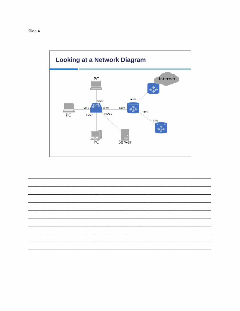
Looking at a Network Diagram
_____________________________________________________________________________________
_____________________________________________________________________________________
_____________________________________________________________________________________
_____________________________________________________________________________________
_____________________________________________________________________________________
_____________________________________________________________________________________
_____________________________________________________________________________________
_____________________________________________________________________________________
_____________________________________________________________________________________
_____________________________________________________________________________________

Slide 5
Applications Found on the Network
Batch types of applications FTP, TFTP, Batch Reports, Inventory Updates
Usually run at scheduled times
Bandwidth is important, but not critical to the application
Interactive Applications: Database queries or updates
User to machine interactions
Users look for quick response times, although important to the users experience, not that critical
Real-time Applications: VoIP, video streams and conferencing
Usually this is user to user interaction
Latency must be avoided, real-time communications require very low latency on the network; this is critical for the application to work properly
_____________________________________________________________________________________
_____________________________________________________________________________________
_____________________________________________________________________________________
_____________________________________________________________________________________
_____________________________________________________________________________________
_____________________________________________________________________________________
_____________________________________________________________________________________
_____________________________________________________________________________________
_____________________________________________________________________________________
_____________________________________________________________________________________

Slide 6
Design Issues of a Network
Topology
Cost
Speed
Security
Availability
Scalability
Reliability
_____________________________________________________________________________________
_____________________________________________________________________________________
_____________________________________________________________________________________
_____________________________________________________________________________________
_____________________________________________________________________________________
_____________________________________________________________________________________
_____________________________________________________________________________________
_____________________________________________________________________________________
_____________________________________________________________________________________
_____________________________________________________________________________________

Slide 7
Physical Topology Types
“Physical Topology” refers to how the network devices are
connected together
The three basic categories are:
Bus
Star
Mesh
_____________________________________________________________________________________
_____________________________________________________________________________________
_____________________________________________________________________________________
_____________________________________________________________________________________
_____________________________________________________________________________________
_____________________________________________________________________________________
_____________________________________________________________________________________
_____________________________________________________________________________________
_____________________________________________________________________________________
_____________________________________________________________________________________

Slide 8
Logical Topologies
A logical topology is the
path through the network
for communications
_____________________________________________________________________________________
_____________________________________________________________________________________
_____________________________________________________________________________________
_____________________________________________________________________________________
_____________________________________________________________________________________
_____________________________________________________________________________________
_____________________________________________________________________________________
_____________________________________________________________________________________
_____________________________________________________________________________________
_____________________________________________________________________________________

Slide 9
Lesson 2
Understanding the Host-to-Host
Communications Model
_____________________________________________________________________________________
_____________________________________________________________________________________
_____________________________________________________________________________________
_____________________________________________________________________________________
_____________________________________________________________________________________
_____________________________________________________________________________________
_____________________________________________________________________________________
_____________________________________________________________________________________
_____________________________________________________________________________________
_____________________________________________________________________________________

Slide 10
Examples of Host-to-Host Communications
There are two different types of Host-to-Host
Communications.
The initial (older) model was:
Usually proprietary (like Novell IPX/SPX)
A 3rd party application using communications software they
developed
Open Standards Model:
OSI or TCP/IP stack both using a layered approach
Multivendor software
_____________________________________________________________________________________
_____________________________________________________________________________________
_____________________________________________________________________________________
_____________________________________________________________________________________
_____________________________________________________________________________________
_____________________________________________________________________________________
_____________________________________________________________________________________
_____________________________________________________________________________________
_____________________________________________________________________________________
_____________________________________________________________________________________

Slide 11
OSI Reference Model
Layer
Number
Name or
Reference
7 Application
6 Presentation
5 Session
4 Transport
3 Network
2 Data Link
1 Physical
_____________________________________________________________________________________
_____________________________________________________________________________________
_____________________________________________________________________________________
_____________________________________________________________________________________
_____________________________________________________________________________________
_____________________________________________________________________________________
_____________________________________________________________________________________
_____________________________________________________________________________________
_____________________________________________________________________________________
_____________________________________________________________________________________
Slide 12
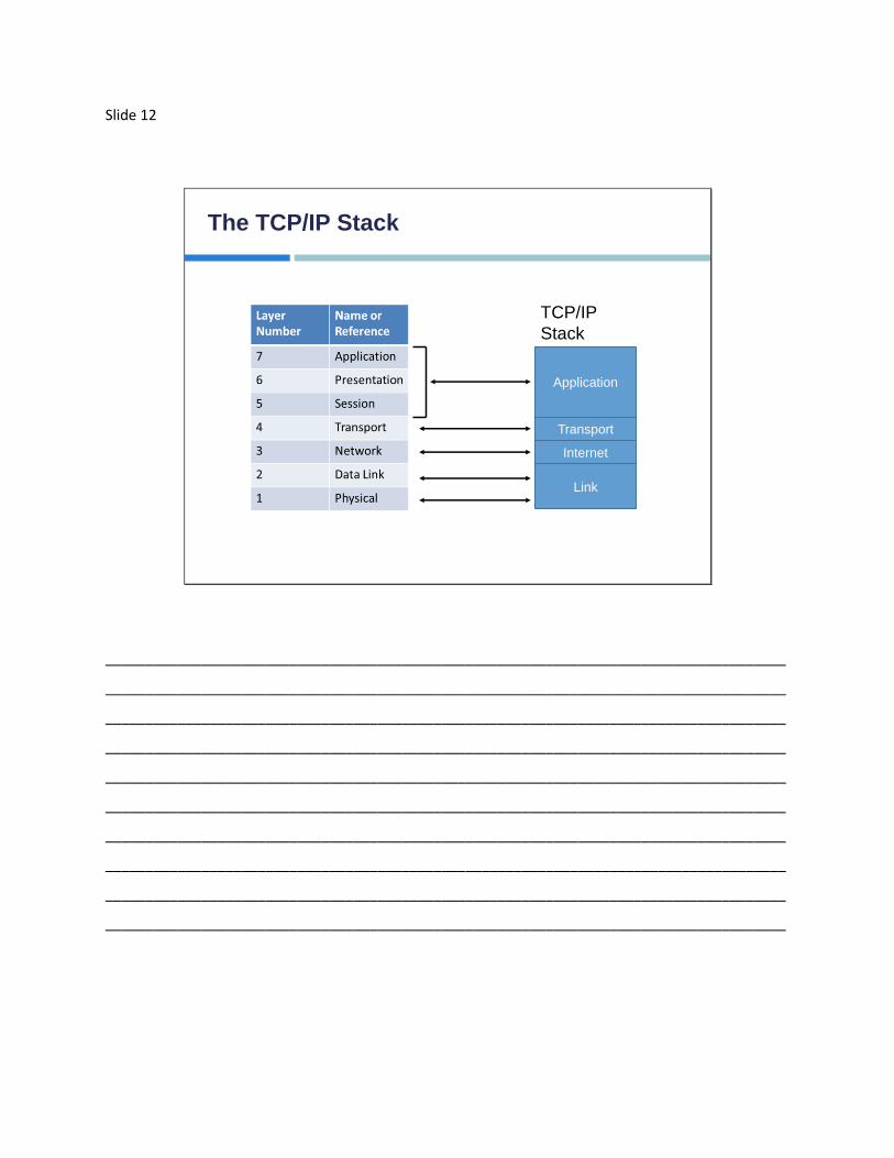
The TCP/IP Stack
Application
Transport
Internet
Link
TCP/IP
Stack
_____________________________________________________________________________________
_____________________________________________________________________________________
_____________________________________________________________________________________
_____________________________________________________________________________________
_____________________________________________________________________________________
_____________________________________________________________________________________
_____________________________________________________________________________________
_____________________________________________________________________________________
_____________________________________________________________________________________
_____________________________________________________________________________________

Slide 13
The Encapsulation Process
Application
Transport
Internet
Network Access
L7-Data
L7-Data
L7-Data
L7-Data
Other HDR
Other HDR
Other HDR
L4
HDRL4
HDRL4
HDR
L3
HDRL3
HDR
L2
HDRFCS
HDR = Header
Sender
_____________________________________________________________________________________
_____________________________________________________________________________________
_____________________________________________________________________________________
_____________________________________________________________________________________
_____________________________________________________________________________________
_____________________________________________________________________________________
_____________________________________________________________________________________
_____________________________________________________________________________________
_____________________________________________________________________________________
_____________________________________________________________________________________

Slide 14
Data De-Encapsulation
Application
Transport
Internet
Network Access
L7-Data
L7-Data
L7-Data
L7-Data
Other HDR
Other HDR
Other HDR
L4
HDRL4
HDRL4
HDR
L3
HDRL3
HDR
L2
HDRFCS
HDR = Header
Receiver
_____________________________________________________________________________________
_____________________________________________________________________________________
_____________________________________________________________________________________
_____________________________________________________________________________________
_____________________________________________________________________________________
_____________________________________________________________________________________
_____________________________________________________________________________________
_____________________________________________________________________________________
_____________________________________________________________________________________
_____________________________________________________________________________________

Slide 15
Communicating Peer-to-Peer
Application
Transport
Network
Link
Application
Transport
Network
Link
Data
Segment
Packet
Frame
PDUs
Sender Receiver
_____________________________________________________________________________________
_____________________________________________________________________________________
_____________________________________________________________________________________
_____________________________________________________________________________________
_____________________________________________________________________________________
_____________________________________________________________________________________
_____________________________________________________________________________________
_____________________________________________________________________________________
_____________________________________________________________________________________
_____________________________________________________________________________________

Slide 16
Lesson 3
Introducing LANs
_____________________________________________________________________________________
_____________________________________________________________________________________
_____________________________________________________________________________________
_____________________________________________________________________________________
_____________________________________________________________________________________
_____________________________________________________________________________________
_____________________________________________________________________________________
_____________________________________________________________________________________
_____________________________________________________________________________________
_____________________________________________________________________________________

Slide 17
Describing the LAN
A Local Area Network (LAN) is usually described
as:
Equipment under your management
High speed data connections
Relatively close (geographically) connected devices
_____________________________________________________________________________________
_____________________________________________________________________________________
_____________________________________________________________________________________
_____________________________________________________________________________________
_____________________________________________________________________________________
_____________________________________________________________________________________
_____________________________________________________________________________________
_____________________________________________________________________________________
_____________________________________________________________________________________
_____________________________________________________________________________________

Slide 18
Components of the LAN
User Devices PCs
Servers
Infrastructure Network Cards
Physical Media
Switches
Routers
Protocols Ethernet
IP
ARP
DHCP
_____________________________________________________________________________________
_____________________________________________________________________________________
_____________________________________________________________________________________
_____________________________________________________________________________________
_____________________________________________________________________________________
_____________________________________________________________________________________
_____________________________________________________________________________________
_____________________________________________________________________________________
_____________________________________________________________________________________
_____________________________________________________________________________________
Slide 19
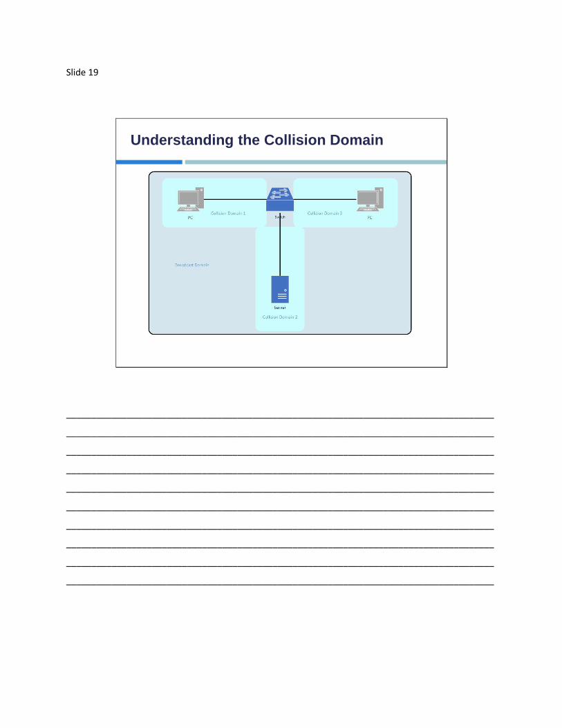
Understanding the Collision Domain
_____________________________________________________________________________________
_____________________________________________________________________________________
_____________________________________________________________________________________
_____________________________________________________________________________________
_____________________________________________________________________________________
_____________________________________________________________________________________
_____________________________________________________________________________________
_____________________________________________________________________________________
_____________________________________________________________________________________
_____________________________________________________________________________________

Slide 20
Understanding the Collision Domain (Cont.)
The Layer 2 Switch should support the following
functions:
Operate at Layer 2 of the OSI and TCP/IP stack
Ethernet Switches will either Forward, Flood, or Filter
frames based on destination MAC Addresses
Support Full-Duplex on its switchports
Operate at high speeds, usually based on an ASIC
architecture
Auto sense speed and duplex settings
_____________________________________________________________________________________
_____________________________________________________________________________________
_____________________________________________________________________________________
_____________________________________________________________________________________
_____________________________________________________________________________________
_____________________________________________________________________________________
_____________________________________________________________________________________
_____________________________________________________________________________________
_____________________________________________________________________________________
_____________________________________________________________________________________

Slide 21
About the Switch
Most Ethernet Switches have the following
characteristics:
High Port Density (compared to a router)
Large frame buffers
Auto sensing speed and duplex per port
Fast internal switching
Average a low cost per port
_____________________________________________________________________________________
_____________________________________________________________________________________
_____________________________________________________________________________________
_____________________________________________________________________________________
_____________________________________________________________________________________
_____________________________________________________________________________________
_____________________________________________________________________________________
_____________________________________________________________________________________
_____________________________________________________________________________________
_____________________________________________________________________________________

Slide 22
Lesson 4
Introduction to the IOS
_____________________________________________________________________________________
_____________________________________________________________________________________
_____________________________________________________________________________________
_____________________________________________________________________________________
_____________________________________________________________________________________
_____________________________________________________________________________________
_____________________________________________________________________________________
_____________________________________________________________________________________
_____________________________________________________________________________________
_____________________________________________________________________________________

Slide 23
Why the IOS
The following are some of the features and
functions of Cisco IOS:
Connectivity to maintain high-speed traffic between
devices
Controlling access and unauthorized use
Allowing for addition of interfaces and capability for
network growth (scalability)
Ensuring access to networked resources
Consistency in user experience from one device to
another
_____________________________________________________________________________________
_____________________________________________________________________________________
_____________________________________________________________________________________
_____________________________________________________________________________________
_____________________________________________________________________________________
_____________________________________________________________________________________
_____________________________________________________________________________________
_____________________________________________________________________________________
_____________________________________________________________________________________
_____________________________________________________________________________________

Slide 24
Basic Functions of the IOS
The IOS is referred to as the CLI (Command Line Interface). Its purpose is to enter commands from the user.
Operations, functions, and features can vary from one type of device to another
Copy and Paste is available to the console/terminal window
The “Enter-key” or “Carriage Return” instructs the IOS to parse and execute the typed command
There are different modes of CLI operation, the EXEC and Configuration Modes
Two default EXEC modes: User and Privileged
_____________________________________________________________________________________
_____________________________________________________________________________________
_____________________________________________________________________________________
_____________________________________________________________________________________
_____________________________________________________________________________________
_____________________________________________________________________________________
_____________________________________________________________________________________
_____________________________________________________________________________________
_____________________________________________________________________________________
_____________________________________________________________________________________

Slide 25
The User EXEC Mode
This is the default mode available when a user
first connects to a switch or router (assuming
not password-protected)
The command prompt will consist of the device “host
name” followed by the greater than (>) sign
_____________________________________________________________________________________
_____________________________________________________________________________________
_____________________________________________________________________________________
_____________________________________________________________________________________
_____________________________________________________________________________________
_____________________________________________________________________________________
_____________________________________________________________________________________
_____________________________________________________________________________________
_____________________________________________________________________________________
_____________________________________________________________________________________

Slide 26
Privileged Exec Mode
Often called “Admin” mode, and allows detailed
examination of how a switch or router is
operating
This is the gateway to configuration mode
Enables configuration and debugging
To move from User Exec to Privileged Exec you must
simply enter the command “enable”
_____________________________________________________________________________________
_____________________________________________________________________________________
_____________________________________________________________________________________
_____________________________________________________________________________________
_____________________________________________________________________________________
_____________________________________________________________________________________
_____________________________________________________________________________________
_____________________________________________________________________________________
_____________________________________________________________________________________
_____________________________________________________________________________________

Slide 27
Privileged EXEC Mode (Cont.)
After switching to Privilege EXEC mode, the
prompt will change to the hostname followed by
a pound (#) sign: hostname#
_____________________________________________________________________________________
_____________________________________________________________________________________
_____________________________________________________________________________________
_____________________________________________________________________________________
_____________________________________________________________________________________
_____________________________________________________________________________________
_____________________________________________________________________________________
_____________________________________________________________________________________
_____________________________________________________________________________________
_____________________________________________________________________________________

Slide 28
Getting CLI Help
CLI Help Options Description
Context-Sensitive Help (using a ?) Lists all available commands and/or
their supported arguments and
parameters for that command
Console Error Messages Identifies if there is a problem with a
command, to help the user identify
how the command must be used or
changed
_____________________________________________________________________________________
_____________________________________________________________________________________
_____________________________________________________________________________________
_____________________________________________________________________________________
_____________________________________________________________________________________
_____________________________________________________________________________________
_____________________________________________________________________________________
_____________________________________________________________________________________
_____________________________________________________________________________________
_____________________________________________________________________________________

Slide 29
Example of Using Context-Sensitive Help
This sequence is showing how the “?” can
provide context sensitive help:
_____________________________________________________________________________________
_____________________________________________________________________________________
_____________________________________________________________________________________
_____________________________________________________________________________________
_____________________________________________________________________________________
_____________________________________________________________________________________
_____________________________________________________________________________________
_____________________________________________________________________________________
_____________________________________________________________________________________
_____________________________________________________________________________________

Slide 30
Example Error Messages
Ambiguous – Not enough of a command was entered
Incomplete – More arguments/parameters are needed
The caret “^” means that character was the first
character that was not recognized as a valid command
_____________________________________________________________________________________
_____________________________________________________________________________________
_____________________________________________________________________________________
_____________________________________________________________________________________
_____________________________________________________________________________________
_____________________________________________________________________________________
_____________________________________________________________________________________
_____________________________________________________________________________________
_____________________________________________________________________________________
_____________________________________________________________________________________

Slide 31
Managing IOS Configurations
Two general types of configurations:
Startup Config: This is the last saved copy of the running configuration, which is
generally loaded on device startup
Absence of this file on a Router will launch the setup mode when the Router
first powers on
Running Config: The current configuration of the device.
Configuration Configuration
RAM NVRAMRunning Configuration Startup Configuration
_____________________________________________________________________________________
_____________________________________________________________________________________
_____________________________________________________________________________________
_____________________________________________________________________________________
_____________________________________________________________________________________
_____________________________________________________________________________________
_____________________________________________________________________________________
_____________________________________________________________________________________
_____________________________________________________________________________________
_____________________________________________________________________________________

Slide 32
Viewing the Running-Config
Using the “show” command, you can easily view the current running-configuration,
but only if you’re in the Privileged EXEC mode
_____________________________________________________________________________________
_____________________________________________________________________________________
_____________________________________________________________________________________
_____________________________________________________________________________________
_____________________________________________________________________________________
_____________________________________________________________________________________
_____________________________________________________________________________________
_____________________________________________________________________________________
_____________________________________________________________________________________
_____________________________________________________________________________________
Slide 33
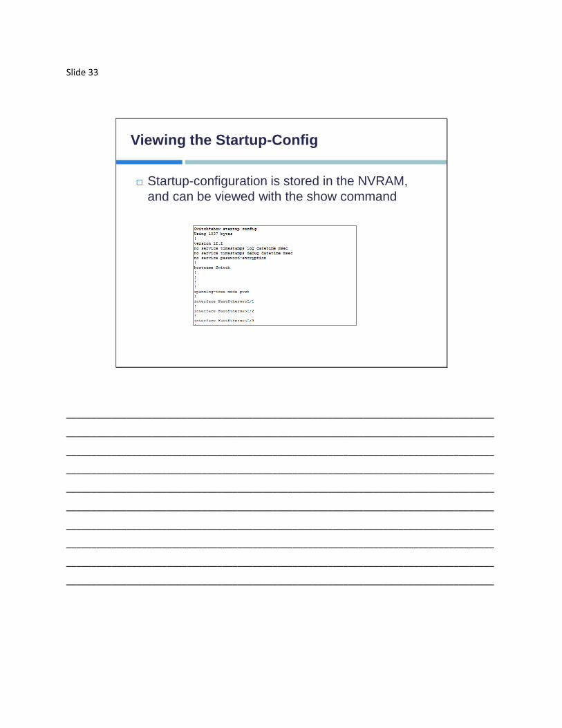
Viewing the Startup-Config
Startup-configuration is stored in the NVRAM,
and can be viewed with the show command
_____________________________________________________________________________________
_____________________________________________________________________________________
_____________________________________________________________________________________
_____________________________________________________________________________________
_____________________________________________________________________________________
_____________________________________________________________________________________
_____________________________________________________________________________________
_____________________________________________________________________________________
_____________________________________________________________________________________
_____________________________________________________________________________________

Slide 34
Managing Cisco IOS Configuration
tftp
ftp
scp
http
…
External Server
_____________________________________________________________________________________
_____________________________________________________________________________________
_____________________________________________________________________________________
_____________________________________________________________________________________
_____________________________________________________________________________________
_____________________________________________________________________________________
_____________________________________________________________________________________
_____________________________________________________________________________________
_____________________________________________________________________________________
_____________________________________________________________________________________

Slide 35
Managing the IOS Configuration
Configuration Configuration
RAM NVRAMRunning Configuration Startup Configuration
Copy running startup
Copy startup running
Configure Terminal (merge)
Copy tftp: running (merge)
Copy run tftp:
Copy tftp: start
Copy start tftp
TFTP Server
blank
Erase start
_____________________________________________________________________________________
_____________________________________________________________________________________
_____________________________________________________________________________________
_____________________________________________________________________________________
_____________________________________________________________________________________
_____________________________________________________________________________________
_____________________________________________________________________________________
_____________________________________________________________________________________
_____________________________________________________________________________________
_____________________________________________________________________________________

Slide 36
Copy Options
Saving the running-config to NVRAM
Backup the running-config to a TFTP Server
_____________________________________________________________________________________
_____________________________________________________________________________________
_____________________________________________________________________________________
_____________________________________________________________________________________
_____________________________________________________________________________________
_____________________________________________________________________________________
_____________________________________________________________________________________
_____________________________________________________________________________________
_____________________________________________________________________________________
_____________________________________________________________________________________

Slide 37
E-MACS
EMAC Command Description
Tab Completes the typing of a command
Ctrl-A Moves to the beginning of a command
Ctrl-E Moves to the end of a command
Backspace Removes one character to the left of the cursor
Ctrl-U Erases a line
Ctrl-Shift-6 (same
time)
Aborts an IOS process such as ping or traceroute
Ctrl-C Aborts the current command and exits the
configuration mode
Ctrl-Z Returns you to Privileged EXEC from Configuration
Mode
_____________________________________________________________________________________
_____________________________________________________________________________________
_____________________________________________________________________________________
_____________________________________________________________________________________
_____________________________________________________________________________________
_____________________________________________________________________________________
_____________________________________________________________________________________
_____________________________________________________________________________________
_____________________________________________________________________________________
_____________________________________________________________________________________

Slide 38
Improving the Use of the CLI
You can utilize the previous command function to the last 10
commands. You can increase this with the terminal history size
option.
The show history command will show you the last X commands
you’ve entered.
_____________________________________________________________________________________
_____________________________________________________________________________________
_____________________________________________________________________________________
_____________________________________________________________________________________
_____________________________________________________________________________________
_____________________________________________________________________________________
_____________________________________________________________________________________
_____________________________________________________________________________________
_____________________________________________________________________________________
_____________________________________________________________________________________

Slide 39
Improving the Use of the CLI (Cont.)
If the content of a show command is long, you’ll see the output
pause, and a –More– option listed at the bottom of the display
Pressing “Enter” will show you the next line of the output
Pressing “spacebar” will show you the next page
This setting can be adjusted as follows:
_____________________________________________________________________________________
_____________________________________________________________________________________
_____________________________________________________________________________________
_____________________________________________________________________________________
_____________________________________________________________________________________
_____________________________________________________________________________________
_____________________________________________________________________________________
_____________________________________________________________________________________
_____________________________________________________________________________________
_____________________________________________________________________________________

Slide 40
Improving the Use of the CLI (Cont.)
You can filter the output of a show command
through the use of pipes (|)
Common filters would be the include or the section
options
_____________________________________________________________________________________
_____________________________________________________________________________________
_____________________________________________________________________________________
_____________________________________________________________________________________
_____________________________________________________________________________________
_____________________________________________________________________________________
_____________________________________________________________________________________
_____________________________________________________________________________________
_____________________________________________________________________________________
_____________________________________________________________________________________

Slide 41
Lesson 5
Starting a Switch
_____________________________________________________________________________________
_____________________________________________________________________________________
_____________________________________________________________________________________
_____________________________________________________________________________________
_____________________________________________________________________________________
_____________________________________________________________________________________
_____________________________________________________________________________________
_____________________________________________________________________________________
_____________________________________________________________________________________
_____________________________________________________________________________________

Slide 42
Installing the Switch
Prior to installation, verify the environment is ready
(Power and/or Cooling)
Physically install the switch
Rack/Wall Mounts
Table/Shelf mount
Verify the cabling is correct
Plug the switch in, then power it on
System will go through normal startup processes such
as POST and Bootstrap
_____________________________________________________________________________________
_____________________________________________________________________________________
_____________________________________________________________________________________
_____________________________________________________________________________________
_____________________________________________________________________________________
_____________________________________________________________________________________
_____________________________________________________________________________________
_____________________________________________________________________________________
_____________________________________________________________________________________
_____________________________________________________________________________________

Slide 43
Understanding the LED Indicators
The following are the LED Indicators
1: System LED
2: Remote Power Supply LED
3-6: Port Mode LEDs
7: Mode Button
8: Port Status LED
_____________________________________________________________________________________
_____________________________________________________________________________________
_____________________________________________________________________________________
_____________________________________________________________________________________
_____________________________________________________________________________________
_____________________________________________________________________________________
_____________________________________________________________________________________
_____________________________________________________________________________________
_____________________________________________________________________________________
_____________________________________________________________________________________

Slide 44
Initial Console Connection
To make the initial connection you will need:
To find the console port
A console cable
(Optionally) a USB-to-Serial port adapter
_____________________________________________________________________________________
_____________________________________________________________________________________
_____________________________________________________________________________________
_____________________________________________________________________________________
_____________________________________________________________________________________
_____________________________________________________________________________________
_____________________________________________________________________________________
_____________________________________________________________________________________
_____________________________________________________________________________________
_____________________________________________________________________________________

Slide 45
Configuration Basics
From privileged EXEC mode, you would need to enter configuration
mode using the command configure terminal
For more specific configuration options, you must navigate to that
configuration hierarchy, for instance to an interface configuration
mode if you wanted to change the interface configuration
_____________________________________________________________________________________
_____________________________________________________________________________________
_____________________________________________________________________________________
_____________________________________________________________________________________
_____________________________________________________________________________________
_____________________________________________________________________________________
_____________________________________________________________________________________
_____________________________________________________________________________________
_____________________________________________________________________________________
_____________________________________________________________________________________
Slide 46
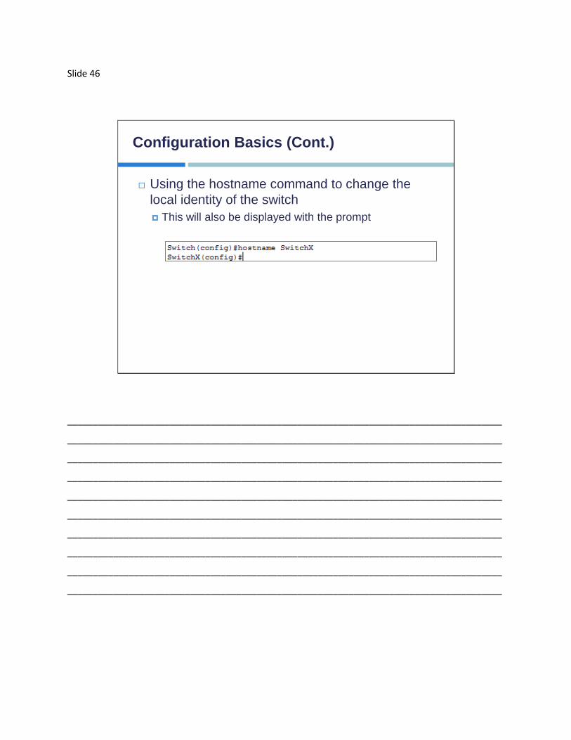
Configuration Basics (Cont.)
Using the hostname command to change the
local identity of the switch
This will also be displayed with the prompt
_____________________________________________________________________________________
_____________________________________________________________________________________
_____________________________________________________________________________________
_____________________________________________________________________________________
_____________________________________________________________________________________
_____________________________________________________________________________________
_____________________________________________________________________________________
_____________________________________________________________________________________
_____________________________________________________________________________________
_____________________________________________________________________________________

Slide 47
Configuration Basics (Cont.)
Assign the default management IP address, including
subnet mask for a switch
You may still have to issue the no shutdown
command even though the VLAN 1 interface is virtual
_____________________________________________________________________________________
_____________________________________________________________________________________
_____________________________________________________________________________________
_____________________________________________________________________________________
_____________________________________________________________________________________
_____________________________________________________________________________________
_____________________________________________________________________________________
_____________________________________________________________________________________
_____________________________________________________________________________________
_____________________________________________________________________________________

Slide 48
Viewing the Initial Startup Status
The show version command is useful to see the system hardware, software
version, serial numbers, and boot images in use
_____________________________________________________________________________________
_____________________________________________________________________________________
_____________________________________________________________________________________
_____________________________________________________________________________________
_____________________________________________________________________________________
_____________________________________________________________________________________
_____________________________________________________________________________________
_____________________________________________________________________________________
_____________________________________________________________________________________
_____________________________________________________________________________________

Slide 49
Viewing the Initial Startup Status (Cont.)
You can verify interface statistics by using the
show interface command
_____________________________________________________________________________________
_____________________________________________________________________________________
_____________________________________________________________________________________
_____________________________________________________________________________________
_____________________________________________________________________________________
_____________________________________________________________________________________
_____________________________________________________________________________________
_____________________________________________________________________________________
_____________________________________________________________________________________
_____________________________________________________________________________________

Slide 50
Viewing the Initial Startup Status (Cont.)
Viewing the active (running) configuration on the switch
_____________________________________________________________________________________
_____________________________________________________________________________________
_____________________________________________________________________________________
_____________________________________________________________________________________
_____________________________________________________________________________________
_____________________________________________________________________________________
_____________________________________________________________________________________
_____________________________________________________________________________________
_____________________________________________________________________________________
_____________________________________________________________________________________

Slide 51
Lesson 6
Understanding Ethernet and Switch Operation
_____________________________________________________________________________________
_____________________________________________________________________________________
_____________________________________________________________________________________
_____________________________________________________________________________________
_____________________________________________________________________________________
_____________________________________________________________________________________
_____________________________________________________________________________________
_____________________________________________________________________________________
_____________________________________________________________________________________
_____________________________________________________________________________________

Slide 52
Media for Ethernet
All transmissions consist of some method to
transmit binary 1’s and 0’s. The mechanics of
how that works depends on the physical media
type.
Coaxial (no longer used in the Enterprise)
Copper (such as twisted pair)
Fiber-optic
Ethernet is a means of encoding information for
transmission, most often for sharing files and other
types of communication
_____________________________________________________________________________________
_____________________________________________________________________________________
_____________________________________________________________________________________
_____________________________________________________________________________________
_____________________________________________________________________________________
_____________________________________________________________________________________
_____________________________________________________________________________________
_____________________________________________________________________________________
_____________________________________________________________________________________
_____________________________________________________________________________________
Slide 53
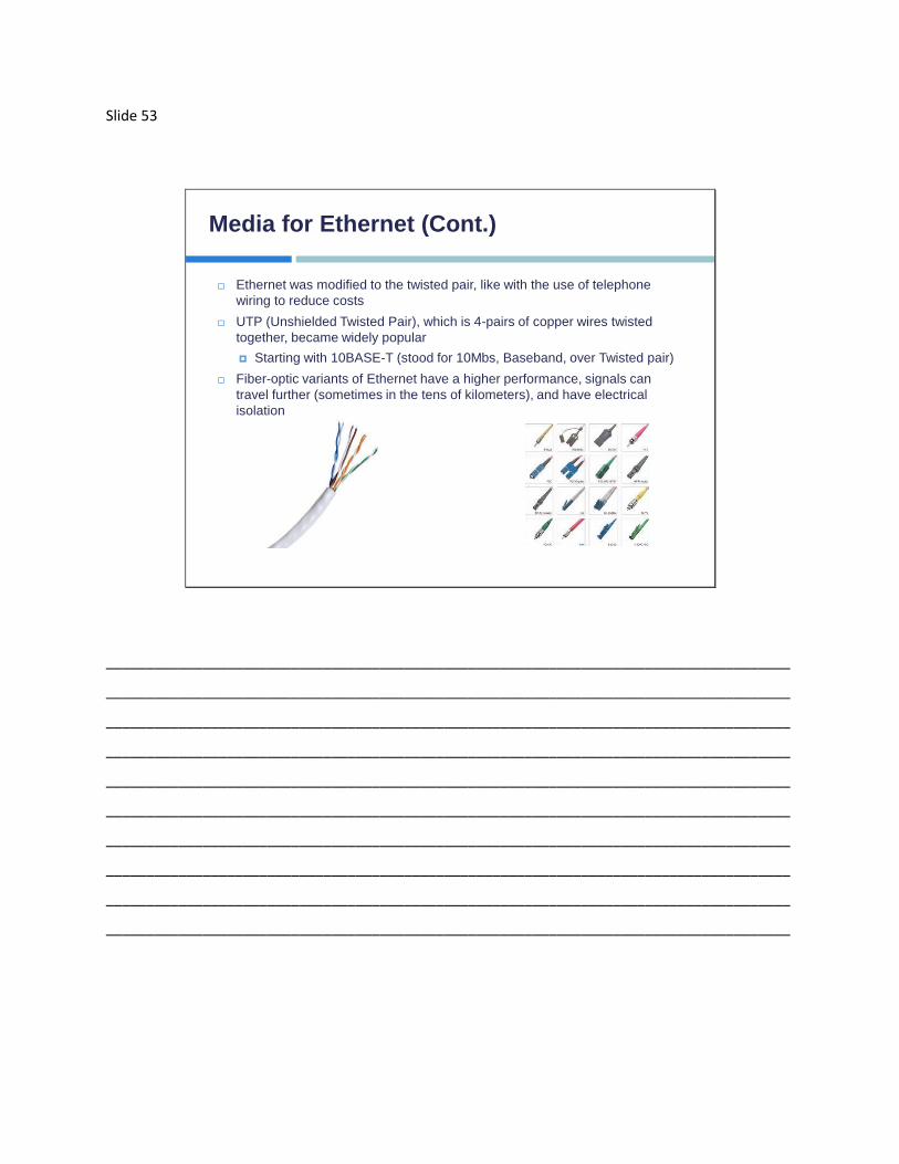
Media for Ethernet (Cont.)
Ethernet was modified to the twisted pair, like with the use of telephone
wiring to reduce costs
UTP (Unshielded Twisted Pair), which is 4-pairs of copper wires twisted
together, became widely popular
Starting with 10BASE-T (stood for 10Mbs, Baseband, over Twisted pair)
Fiber-optic variants of Ethernet have a higher performance, signals can
travel further (sometimes in the tens of kilometers), and have electrical
isolation
_____________________________________________________________________________________
_____________________________________________________________________________________
_____________________________________________________________________________________
_____________________________________________________________________________________
_____________________________________________________________________________________
_____________________________________________________________________________________
_____________________________________________________________________________________
_____________________________________________________________________________________
_____________________________________________________________________________________
_____________________________________________________________________________________

Slide 54
Media for Ethernet (Cont.)
The most popular media for the small enterprise
is the UTP option
Characteristic Value
Speed or Bandwidth Between 10Mb/s to 10 Gb/s
Price Least Expensive Option
Media and connector
size
Small
Maximum cable run Varies on Bandwidth and CAT
Type
Outer Jacket
Color Coded Plastic Insulation
RJ-45 Connector
_____________________________________________________________________________________
_____________________________________________________________________________________
_____________________________________________________________________________________
_____________________________________________________________________________________
_____________________________________________________________________________________
_____________________________________________________________________________________
_____________________________________________________________________________________
_____________________________________________________________________________________
_____________________________________________________________________________________
_____________________________________________________________________________________

Slide 55
Media for Ethernet (Cont.)
RJ-45 Connector and the RJ-45 Jack
_____________________________________________________________________________________
_____________________________________________________________________________________
_____________________________________________________________________________________
_____________________________________________________________________________________
_____________________________________________________________________________________
_____________________________________________________________________________________
_____________________________________________________________________________________
_____________________________________________________________________________________
_____________________________________________________________________________________
_____________________________________________________________________________________

Slide 56
Media for Ethernet (Cont.)
Single Mode Optical Fiber Example
_____________________________________________________________________________________
_____________________________________________________________________________________
_____________________________________________________________________________________
_____________________________________________________________________________________
_____________________________________________________________________________________
_____________________________________________________________________________________
_____________________________________________________________________________________
_____________________________________________________________________________________
_____________________________________________________________________________________
_____________________________________________________________________________________

Slide 57
Media for Ethernet (Cont.)
_____________________________________________________________________________________
_____________________________________________________________________________________
_____________________________________________________________________________________
_____________________________________________________________________________________
_____________________________________________________________________________________
_____________________________________________________________________________________
_____________________________________________________________________________________
_____________________________________________________________________________________
_____________________________________________________________________________________
_____________________________________________________________________________________

Slide 58
Media for Ethernet (Cont.)
Types of Fiber Cable Connectors
_____________________________________________________________________________________
_____________________________________________________________________________________
_____________________________________________________________________________________
_____________________________________________________________________________________
_____________________________________________________________________________________
_____________________________________________________________________________________
_____________________________________________________________________________________
_____________________________________________________________________________________
_____________________________________________________________________________________
_____________________________________________________________________________________

Slide 59
Ethernet Frames
The Ethernet Frame
Size in
Bytes
8 6 6 2 46-1500 4
Content Preamble Destination
MAC
Source
MAC
Ether-
Type
Data Frame
Check
Sequence
_____________________________________________________________________________________
_____________________________________________________________________________________
_____________________________________________________________________________________
_____________________________________________________________________________________
_____________________________________________________________________________________
_____________________________________________________________________________________
_____________________________________________________________________________________
_____________________________________________________________________________________
_____________________________________________________________________________________
_____________________________________________________________________________________

Slide 60
Communication Types
Unicast
Broadcast
Multicast
Example of a Client Group
_____________________________________________________________________________________
_____________________________________________________________________________________
_____________________________________________________________________________________
_____________________________________________________________________________________
_____________________________________________________________________________________
_____________________________________________________________________________________
_____________________________________________________________________________________
_____________________________________________________________________________________
_____________________________________________________________________________________
_____________________________________________________________________________________

Slide 61
Introducing the MAC Address
The Ethernet MAC Address is 48bits in size (6 bytes)
The first 24bits (3 bytes) is the OUI
The last 24bits (3 bytes) is Vendor Assigned
OUI – 24 bitsVendor Assigned
24 bits
_____________________________________________________________________________________
_____________________________________________________________________________________
_____________________________________________________________________________________
_____________________________________________________________________________________
_____________________________________________________________________________________
_____________________________________________________________________________________
_____________________________________________________________________________________
_____________________________________________________________________________________
_____________________________________________________________________________________
_____________________________________________________________________________________

Slide 62
Introducing the MAC Address (Cont.)
Depending on the vendor’s software, the MAC
Address may be displayed in different formats
This is still a hexadecimal value, it’s only the display
that looks different
0000.0c43.2e08 (dots separation)
00:00:0c:43:2e:08 (colon between each 8 bits)
00-00-0c-43-2e-08 (hyphen separating each 8 bits)
_____________________________________________________________________________________
_____________________________________________________________________________________
_____________________________________________________________________________________
_____________________________________________________________________________________
_____________________________________________________________________________________
_____________________________________________________________________________________
_____________________________________________________________________________________
_____________________________________________________________________________________
_____________________________________________________________________________________
_____________________________________________________________________________________

Slide 63
How the Switch Works
frame
1
1
2
3
2
3
fram
e
frame
MAC Table
Port 1: MAC – A
Port 2: Empty
Port 3: Empty
MAC Table
Port 1: MAC – A
Port 2: Empty
Port 3: Empty
_____________________________________________________________________________________
_____________________________________________________________________________________
_____________________________________________________________________________________
_____________________________________________________________________________________
_____________________________________________________________________________________
_____________________________________________________________________________________
_____________________________________________________________________________________
_____________________________________________________________________________________
_____________________________________________________________________________________
_____________________________________________________________________________________

Slide 64
How the Switch Works (Cont.)
frame
1
1
2
3
2
3
frame
MAC Table
Port 1: MAC – A
Port 2: Empty
Port 3: MAC - B
MAC Table
Port 1: MAC – A
Port 2: Empty
Port 3: MAC - B
_____________________________________________________________________________________
_____________________________________________________________________________________
_____________________________________________________________________________________
_____________________________________________________________________________________
_____________________________________________________________________________________
_____________________________________________________________________________________
_____________________________________________________________________________________
_____________________________________________________________________________________
_____________________________________________________________________________________
_____________________________________________________________________________________

Slide 65
Understanding Duplex
Half-Duplex means:
You can transmit or receive, but
not at the same time
This is unidirectional communications
Older technology
_____________________________________________________________________________________
_____________________________________________________________________________________
_____________________________________________________________________________________
_____________________________________________________________________________________
_____________________________________________________________________________________
_____________________________________________________________________________________
_____________________________________________________________________________________
_____________________________________________________________________________________
_____________________________________________________________________________________
_____________________________________________________________________________________

Slide 66
Understanding Duplex (Cont.)
Full-Duplex operation:
Point to Point only,
no shared media
Both ends must support
full-duplex
_____________________________________________________________________________________
_____________________________________________________________________________________
_____________________________________________________________________________________
_____________________________________________________________________________________
_____________________________________________________________________________________
_____________________________________________________________________________________
_____________________________________________________________________________________
_____________________________________________________________________________________
_____________________________________________________________________________________
_____________________________________________________________________________________

Slide 67
Configuring Duplex and Speed
This example shows you how to manually configure speed and
duplex for interface FastEthernet 0/1
The next part of that configuration shows you how to set auto-
duplex and auto-speed on interface FastEthernet 0/5
_____________________________________________________________________________________
_____________________________________________________________________________________
_____________________________________________________________________________________
_____________________________________________________________________________________
_____________________________________________________________________________________
_____________________________________________________________________________________
_____________________________________________________________________________________
_____________________________________________________________________________________
_____________________________________________________________________________________
_____________________________________________________________________________________

Slide 68
Results of Duplex Settings
Duplex Setting Half Full Auto
Half Half Mismatch Half
Full Mismatch Full Full
Auto Half Full Full
_____________________________________________________________________________________
_____________________________________________________________________________________
_____________________________________________________________________________________
_____________________________________________________________________________________
_____________________________________________________________________________________
_____________________________________________________________________________________
_____________________________________________________________________________________
_____________________________________________________________________________________
_____________________________________________________________________________________
_____________________________________________________________________________________

Slide 69
Results of Duplex/Speed Settings
The Show Interface command will allow you to view the current
duplex and speed on an interface
_____________________________________________________________________________________
_____________________________________________________________________________________
_____________________________________________________________________________________
_____________________________________________________________________________________
_____________________________________________________________________________________
_____________________________________________________________________________________
_____________________________________________________________________________________
_____________________________________________________________________________________
_____________________________________________________________________________________
_____________________________________________________________________________________

Slide 70
Lesson 7
Troubleshooting Common Switch Media Issues
_____________________________________________________________________________________
_____________________________________________________________________________________
_____________________________________________________________________________________
_____________________________________________________________________________________
_____________________________________________________________________________________
_____________________________________________________________________________________
_____________________________________________________________________________________
_____________________________________________________________________________________
_____________________________________________________________________________________
_____________________________________________________________________________________

Slide 71
Troubleshooting Tools
Using PING to test connectivity
_____________________________________________________________________________________
_____________________________________________________________________________________
_____________________________________________________________________________________
_____________________________________________________________________________________
_____________________________________________________________________________________
_____________________________________________________________________________________
_____________________________________________________________________________________
_____________________________________________________________________________________
_____________________________________________________________________________________
_____________________________________________________________________________________
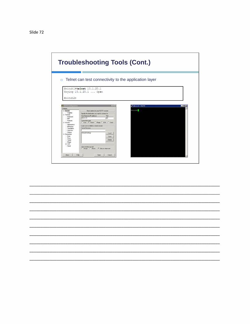
Slide 72
Troubleshooting Tools (Cont.)
Telnet can test connectivity to the application layer
_____________________________________________________________________________________
_____________________________________________________________________________________
_____________________________________________________________________________________
_____________________________________________________________________________________
_____________________________________________________________________________________
_____________________________________________________________________________________
_____________________________________________________________________________________
_____________________________________________________________________________________
_____________________________________________________________________________________
_____________________________________________________________________________________

Slide 73
Problems with Media
Copper media can have several issues that
cause problems:
EMI sources causing noise
Damage to the cable itself
Change in traffic flow causing congestion
Installation of new equipment
_____________________________________________________________________________________
_____________________________________________________________________________________
_____________________________________________________________________________________
_____________________________________________________________________________________
_____________________________________________________________________________________
_____________________________________________________________________________________
_____________________________________________________________________________________
_____________________________________________________________________________________
_____________________________________________________________________________________
_____________________________________________________________________________________

Slide 74
Problems with Media (Cont.)
Fiber can also have issues that affect communications:
Macrobend losses:
Fiber can’t be bent into too small a radius or light can escape
This means that the light does not reflect correctly off of the cladding,
which could lead to loss of light
Improper splicing also causes loss of light
Radius greater than
25-30mm = No Loss
_____________________________________________________________________________________
_____________________________________________________________________________________
_____________________________________________________________________________________
_____________________________________________________________________________________
_____________________________________________________________________________________
_____________________________________________________________________________________
_____________________________________________________________________________________
_____________________________________________________________________________________
_____________________________________________________________________________________
_____________________________________________________________________________________

Slide 75
Troubleshooting Flow Chart
_____________________________________________________________________________________
_____________________________________________________________________________________
_____________________________________________________________________________________
_____________________________________________________________________________________
_____________________________________________________________________________________
_____________________________________________________________________________________
_____________________________________________________________________________________
_____________________________________________________________________________________
_____________________________________________________________________________________
_____________________________________________________________________________________

Slide 76
Understanding Interface Status
Using show interface command
Interface Status Line Protocol
Status
Link State
Up Up Operational
Up Down Connection issue
Down Down (not
connected)
Cable unplugged, or other
side is disconnected or shut
down
Down Down Interface problem
Administratively
Down
Down Disabled
_____________________________________________________________________________________
_____________________________________________________________________________________
_____________________________________________________________________________________
_____________________________________________________________________________________
_____________________________________________________________________________________
_____________________________________________________________________________________
_____________________________________________________________________________________
_____________________________________________________________________________________
_____________________________________________________________________________________
_____________________________________________________________________________________

Slide 77
Understanding Interface Statistics
Excessive collisions:
This naturally occurs with half-duplex
Try to change to full-duplex
Change both sides to have the same duplex settings
Excessive late collisions:
Usually a duplex mismatch
Configure the link to use full-duplex
Change both sides to have the same duplex settings
Excessive Noise:
Usually indicated by too many CRC errors
Check cable for damage or excessive length
There may also be another source of noise, such as electrical devices too close
_____________________________________________________________________________________
_____________________________________________________________________________________
_____________________________________________________________________________________
_____________________________________________________________________________________
_____________________________________________________________________________________
_____________________________________________________________________________________
_____________________________________________________________________________________
_____________________________________________________________________________________
_____________________________________________________________________________________
_____________________________________________________________________________________

Slide 78
Interface Statistics
Interface
Statistics
_____________________________________________________________________________________
_____________________________________________________________________________________
_____________________________________________________________________________________
_____________________________________________________________________________________
_____________________________________________________________________________________
_____________________________________________________________________________________
_____________________________________________________________________________________
_____________________________________________________________________________________
_____________________________________________________________________________________
_____________________________________________________________________________________

Slide 79
Port Problems
Most common port problems can be associated
with duplex and speed mismatches
Verify the duplex settings match on both ends of the
cable
Verify the speed settings match on both ends of the
cable
_____________________________________________________________________________________
_____________________________________________________________________________________
_____________________________________________________________________________________
_____________________________________________________________________________________
_____________________________________________________________________________________
_____________________________________________________________________________________
_____________________________________________________________________________________
_____________________________________________________________________________________
_____________________________________________________________________________________
_____________________________________________________________________________________

Slide 80
Port Problems (Cont.)
Some examples of the duplex mismatches are:
One end set to half, the other end set to full
One end set to full, the other set to auto
If Auto-Negotiation fails, it will default to half
One end set to half, the other set to auto
If Auto-Negotiation fails, it will default to half
No mismatch would then occur
_____________________________________________________________________________________
_____________________________________________________________________________________
_____________________________________________________________________________________
_____________________________________________________________________________________
_____________________________________________________________________________________
_____________________________________________________________________________________
_____________________________________________________________________________________
_____________________________________________________________________________________
_____________________________________________________________________________________
_____________________________________________________________________________________

Slide 81
Port Problems (Cont.)
Other duplex examples are:
Autonegotiation is set on both ends:
One side fails to full duplex, and the other end fails to half
duplex
A Gigabit Ethernet interface defaults to full duplex, while a
10/100 defaults to half duplex
Autonegotiation is set on both ends:
If both sides fail to half, then there is no mismatch
Autonegotiation fails on both ends, and they both revert to half
duplex
_____________________________________________________________________________________
_____________________________________________________________________________________
_____________________________________________________________________________________
_____________________________________________________________________________________
_____________________________________________________________________________________
_____________________________________________________________________________________
_____________________________________________________________________________________
_____________________________________________________________________________________
_____________________________________________________________________________________
_____________________________________________________________________________________

Slide 82
Port Problems (Cont.)
Here are some of the issues relating to speed settings:
Each end is set to a different speed then a mismatch
occurs
One side set to a specific speed, the other side set to
auto
If auto-negotiation fails, switch will sense what the other side is
using to revert to the best speed
Auto is set on both ends
Auto fails on both sides, they then revert to their slowest speed
and then there would be no mismatch
_____________________________________________________________________________________
_____________________________________________________________________________________
_____________________________________________________________________________________
_____________________________________________________________________________________
_____________________________________________________________________________________
_____________________________________________________________________________________
_____________________________________________________________________________________
_____________________________________________________________________________________
_____________________________________________________________________________________
_____________________________________________________________________________________

Slide 83
Troubleshooting Flow Chart
Follow this flow chart for troubleshooting port setting
issues:
_____________________________________________________________________________________
_____________________________________________________________________________________
_____________________________________________________________________________________
_____________________________________________________________________________________
_____________________________________________________________________________________
_____________________________________________________________________________________
_____________________________________________________________________________________
_____________________________________________________________________________________
_____________________________________________________________________________________
_____________________________________________________________________________________

Slide 84
Troubleshooting Port Issues
Display the duplex and speed settings with the show interface
command
_____________________________________________________________________________________
_____________________________________________________________________________________
_____________________________________________________________________________________
_____________________________________________________________________________________
_____________________________________________________________________________________
_____________________________________________________________________________________
_____________________________________________________________________________________
_____________________________________________________________________________________
_____________________________________________________________________________________
_____________________________________________________________________________________


Review Questions:
1. You download a file from an FTP site on the Internet. What is the highest layer in
the OSI model used in this FTP operation?
A. Application
B. Presentation
C. Session
D. Transport
2. A host computer has been correctly configured with a static IP address, but the
default gateway is incorrectly set. Which layer of the OSI model will be first
affected by this configuration error?
A. Layer 1
B. Layer 2
C. Layer 3
D. Layer 4
3. Which layer of the OSI reference model is responsible for ensuring reliable end-
to-end delivery of data?
A. Application
B. Presentation
C. Session
D. Transport
4. In the communications industry, what are the features and benefits of using the
layered OSI model?
A. It encourages industry standardization by defining what functions occur at
each layer of the model
B. It necessitates changes in functionality in one layer to other layers
C. It enables equipment efficiency from different vendors to use the same
electronic components
D. It divides the network communication process into smaller and simpler
components, thus aiding component development, design, and
troubleshooting
E. A & B
F. C & D
G. A & D

5. At which layer of the OSI model is the optimal path to a network destination
determined at?
A. Data Link
B. Session
C. Physical
D. Network
6. Which OSI layer header contains the address of a destination host that is another
network?
A. Application
B. Presentation
C. Network
D. Transport
7. A network device connects to the network through an interface for the
corresponding media type. This device is known as a NIC; what does NIC stand
for?
A. Next Interchange Connection
B. Network Interface Card
C. Now In Charge
D. Network Independent Charge
8. A kilobyte is how many bytes?
A. 1,000
B. 1,000,000
C. 100
D. 10,000
9. When moving from the upper layers of the OSI model to the lower layers, the
information for each layer is added on as headers, and this process is known as
what?
A. De-encapsulation
B. Packet Padding
C. Encapsulation
D. Compression

10. What layer of the OSI model do the protocols Ethernet, PPP, and frame-relay
operate on?
A. Layer 4
B. Layer 3
C. Layer 2
D. Layer 1

Answer Key:
1. A
The highest layer in the OSI model is layer 7, the Application layer. This layer
describes the use of end-user applications, such as Microsoft Office applications,
Internet browsers, Telnet, and FTP.
2. C
IP Addressing and IP Routing reside on the OSI Network layer, which is layer 3.
3. D
A key function of the Transport layer is to provide connection services for the
protocols and applications that run at the levels above it. Transport layer
protocols are given intelligence in the form of algorithms that ensure reliable and
efficient communication between devices. This encompasses several related
jobs, including lost transmission detection and handling, and managing the
rate at which data is sent, to ensure that the receiving device is not
overwhelmed.
4. G
The OSI (Open System Interconnection) reference model was created as a
reference point for communications devices. A layered approach is used to
segment the entire telecommunications process into a series of smaller steps. A
is correct because it encourages a level of standardization by encouraging that
functions be compared to known layers. D is also correct because it allows
engineers to focus on the development, refining, and perfection of simpler
components.
5. D
The Network layer (Internet layer in the TCP/IP model) provides logical
addressing and routing through an internetwork. The Network layer is layer 3 of
the OSI model.
6. C
Only network address contains this information. To transmit the packets, the
sender uses network address and data link address. But the layer 2 address
represents just the address of the next hop device on the way to the sender,
and is changed on each hop. Network address remains the same.

7. B
This is an interface to the appropriate network media, hence the name Network
Interface Card.
8. A
This is 1,000 bytes; kilo stands for 1000. Technically, this is really 2 to the power
of 10, which is really 1024 bytes, but in practice, we round this down to 1000
based on the prefix of KILO.
9. C
Encapsulation describes the method of putting these headers around the original
data as the data moves down the stack.
10. C
These are all layer 2 encapsulation protocols.


