Interconnection Feasibility Study Report GIP-IR577-FEAS-R1 Generator Interconnection Request 577 150 MW Wind Generating Facility Cumberland County, NS 2021-03-04 Control Centre Operations Nova Scotia Power Inc.
Transcript
Interconnection Feasibility Study Report
GIP-IR577-FEAS-R1
Generator Interconnection Request 577
150 MW Wind Generating Facility
Cumberland County, NS
2021-03-04
Control Centre Operations Nova Scotia Power Inc.
Control Centre Operations – Interconnection Feasibility Study Report
ii
Executive Summary The Interconnection Customer (IC) submitted an Interconnection Request (IR#577) for Network Resource Interconnection Service (NRIS) for a proposed 150 MW wind generation facility
interconnected to the NSPI transmission system, with a Commercial Operation Date of 2022-12-31. The Point of Interconnection (POI) requested by the customer is the 138kV bus at 1N-Onslow. The IC proposes to build a spur line from their Higgins Mountain site to tap into the surplus line L-6513 approximately 20km north of the Debert substation. L-6513 runs between 1N-Onslow and
74N-Springhill although it was disconnected from the system at both ends when it was replaced by line L-6613. Line L-6613 uses the 138kV bus nodes and breakers that were previously utilized by L-6513, and it is routed in the same ROW as line L-6513.
There are five transmission and four distribution Interconnection Requests currently in the Advanced Stage Transmission and Distribution Queue that must be included in the study models for IR#577. In addition, there is one long-term firm transmission service reservation in the amount of 800 MW from New Brunswick to Nova Scotia (TSR-411), and one 500MW long-term firm
transmission service request from Newfoundland to Nova Scotia (TSR-412) that also must be accounted for. The two transmission service requests are expected to be in service in 2025 and system studies are currently underway to determine the associated upgrades to the Nova Scotia transmission system. These upgrades are expected to materially alter the configuration of the
transmission system in Nova Scotia. As a result, the following notice has been posted to the OASIS site at https://www.nspower.ca/oasis/generation-interconnection-procedures:
Effective January 19th, 2021, please be advised that the completion of advanced-stage
Interconnection Studies under the Standard Generator Interconnection Procedures (GIP) may be delayed pending the outcome of the Transmission Service Request (TSR) 411 and 412 System Impact Studies, which are expected to identify significant changes to the NSPI transmission system. The expected completion date for these studies is December 31, 2021.
Feasibility Studies initiated prior to the completion of these TSR System Impact Studies will be performed based on the current system configuration.
This study identified transmission contingencies inside Nova Scotia which would violate thermal
loading criteria and estimated the cost of necessary upgrades to allow for full NRIS operation. In particular, the addition of 100-150MVAR of fixed capacitor banks will be required at either 67N-Onslow or 103H-Lakeside to maintain system voltage in cases where IR#577 generation raises flows on the Onslow South transfer corridor above the present limit of 975 MW.
The assessment of the POI on the 138 kV line L-6513 indicated that upgrades would be necessary to deliver 150 MW without exceeding emergency thermal ratings of equipment. The sections of L-6513 between the POI in 1N-Onslow and the line extension tap point are limited by the conductor thermal rating and operating temperature. The line rating must be upgraded to 70°C to
accommodate the full 150MW proposed in IR#577. Line L-6613 utilized the termination facilities that had been associated with L-6513 when it entered service. As such, a new 138kV breaker, related switchgear, and line terminal will be
required at 1N-Onslow to reconnect L-6513 to the 138kV bus.
Control Centre Operations – Interconnection Feasibility Study Report
iii
Data provided by the IC indicates that IR#577 may be able to meet reactive requirements without additional reactive support. Based on the provided rated power factor of the GE 3.8-130 wind turbines and the provided impedances of the transformers, supplementary reactive support may be
sufficient to meet the net power factor of +0.95 to -0.95 at the Interconnection Facility 138kV bus. As specific details of the collector circuits were not available at this time, the need for supplemental reactive power support will be further investigated in the System Impact Study.
No concern regarding high short-circuit level or voltage flicker was found for this project on its own, provided that the project design meets NSPI requirements for low-voltage ride-through, reactive power range and voltage control system. Harmonics must meet the Total Harmonics Distortion provisions of IEEE 519. Short Circuit Ratio may be an issue for inverter-based
generation controls. The minimum short circuit level at the Interconnection Facility 138kV bus is 556 MVA with all lines in service, and 538 MVA with L-6613 out of service. The 1N-Onslow POI for IR#577 is part of the Nova Scotia Bulk Power System. As such,
protections at 1N-Onslow must comply with NPCC Directory 4 requirements. The IR#577 Interconnection Customer substation at Higgins Mountain is not part of the Bulk Power System, and therefore protection systems at that site do not need to meet NPCC BPS criteria. The 1N-Onslow substation is also classified as part of the NERC Bulk Electric System (BES), subject to
the applicable NERC Reliability Criteria. As IR#577 has dispersed generation totalling more than 75MVA, each generator will be classified as a BES element, as will the 138kV bus at Higgins Mountain. The collector systems will not be BES, nor will each of the three 138kV-34.5kV site transformers as individually they carry < 75MVA of aggregate generation.
The preliminary value for the unit loss factor is calculated as 3.93% at the POI at 1N-Onslow. The preliminary non-binding cost estimate for interconnecting 150 MW to the 1N-Onslow 138kV
bus, including the cost of the fixed capacitors and the new spur line is $16,967,5001. The cost estimate includes a contingency of 10%, and this estimate will be further refined in the System Impact Study and the Facility Study. $11,220,000 of this amount represents Transmission Provider’s Interconnection Facilities costs, which are fully funded by the customer. The remaining
$5,747,500 represents Network Upgrade costs, which are funded by the customer but which are eligible for refund under the terms of the GIP. The estimated time to construct the Transmission Providers Interconnection Facilities is 18-24 months after receipt of funds and cleared right of way from the customer.
1 The Feasibility study analysis was based on a 15km spur line. The cost estimate was revised to show a 10km spur line at the customer’s request
Control Centre Operations – Interconnection Feasibility Study Report
1 Introduction The Interconnection Customer (IC) submitted an Interconnection Request (IR#577) for Network Resource Interconnection Service (NRIS) for a proposed 150 MW wind
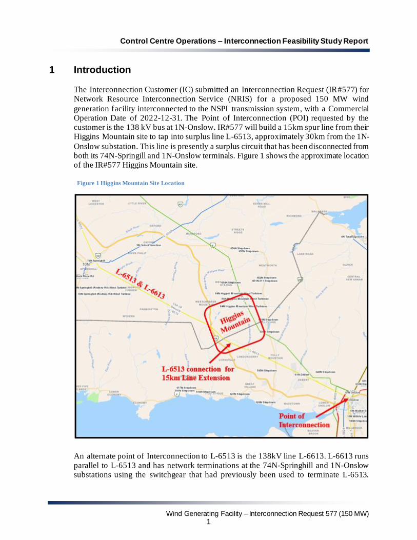
generation facility interconnected to the NSPI transmission system, with a Commercial Operation Date of 2022-12-31. The Point of Interconnection (POI) requested by the customer is the 138 kV bus at 1N-Onslow. IR#577 will build a 15km spur line from their Higgins Mountain site to tap into surplus line L-6513, approximately 30km from the 1N-
Onslow substation. This line is presently a surplus circuit that has been disconnected from both its 74N-Springill and 1N-Onslow terminals. Figure 1 shows the approximate location of the IR#577 Higgins Mountain site.
Figure 1 Higgins Mountain Site Location
An alternate point of Interconnection to L-6513 is the 138kV line L-6613. L-6613 runs parallel to L-6513 and has network terminations at the 74N-Springhill and 1N-Onslow substations using the switchgear that had previously been used to terminate L-6513.
Control Centre Operations – Interconnection Feasibility Study Report
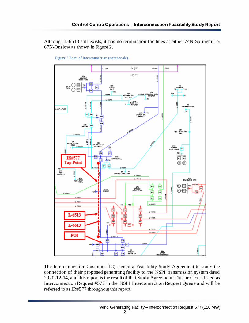
Although L-6513 still exists, it has no termination facilities at either 74N-Springhill or 67N-Onslow as shown in Figure 2.
Figure 2 Point of Interconnection (not to scale)
The Interconnection Customer (IC) signed a Feasibility Study Agreement to study the connection of their proposed generating facility to the NSPI transmission system dated 2020-12-14, and this report is the result of that Study Agreement. This project is listed as Interconnection Request #577 in the NSPI Interconnection Request Queue and will be
referred to as IR#577 throughout this report.
Control Centre Operations – Interconnection Feasibility Study Report
2 Scope The objective of this Interconnection Feasibility Study (FEAS) is to provide a preliminary evaluation of system impacts from interconnecting the proposed generation facility to the
NSPI transmission system at the requested location. The assessment will identify potential impacts on transmission element loading, which must remain within their thermal limits. Any potential violations of voltage criteria will be identified and addressed. If the proposed generation increases the short-circuit duty of any circuit breakers beyond their rated
capacity, the circuit breakers must be upgraded. Single contingency criteria are applied. The scope of the FEAS includes the modelling of the power system in normal state (with all transmission elements in service) under anticipated load and generation dispatch
conditions. A power flow and short circuit analysis will be performed to provide the following information: • Preliminary identification of any circuit breaker short circuit capability limits exceeded
as a result of the interconnection, and any network upgrades necessary to address the short circuit issues associated with the IR.
• Preliminary identification of any thermal overload or voltage limit violations resulting
from the interconnection and identification of the necessary network upgrades to allow full output of the proposed facility.
• Preliminary description and high-level non-binding estimated cost and time to
construct the facilities required to interconnect the generating facility to the transmission system.
This FEAS is based on a power flow and short circuit analysis and does not include a
complete determination of facility changes/additions required to increase the system transfer capabilities that may be required to meet the design and operating criteria established by NSPI, the Northeast Power Coordinating Council (NPCC), and the North American Electric Reliability Corporation (NERC). These requirements will be determined
by a more detailed analysis in the subsequent interconnection System Impact Study (SIS). An Interconnection Facilities Study (FAC) follows the SIS to ascertain the final cost estimate to the interconnect the generating facility.
3 Assumptions
This FEAS is based on the technical information provided by the Interconnection Customer. The Point of Interconnection (POI) and configuration is studied as follows:
1. Network Resource Interconnection Service (NRIS) type per section 3.2 of the Generator Interconnection procedures (GIP).
Control Centre Operations – Interconnection Feasibility Study Report
3. The Interconnection Facility consists of up to 50 GE130, 3.8MW, Type 3 DFAG
(Double Fed Asynchronous Generators) units, capped at a total of 150MW, connected to six collector circuits via three 30/40/53 MVA generator step up transformers.
4. The POI is located at the 138kV bus at the 1N-Onslow substation. The IC has indicated
on their system 1-line diagram that the Interconnection Facility will be connected to the POI via a new 15km spur line built to 138 kV standards using 795 kcmil Drake conductor, plus the first 30km of NSPI’s surplus 138kV line L-6513.
5. The generation technology used must meet NSPI requirements for reactive power capability of at least 0.95 capacitive to 0.95 inductive at the HV terminals of the IC Substation Step Up transformer. It is also required to have high-speed Automatic Voltage Regulation to maintain constant voltage at the designated voltage control point
during and following system disturbances as determined in the subsequent System Impact Study. The designated voltage control point will either be the low voltage terminals of the wind farm transformer, or if the high voltage terminals are used, equipped with droop compensation controls. It is assumed that the generating units are
not de-rated in their MW capability when delivering the required reactive power to the system.
6. Preliminary data was provided by the IC for the IC substation step-up transformers.
Modeling for the primary interconnection point was conducted with three 138 kV - 34.5 kV transformers each rated 30/40/53 MVA. An equivalent Interconnection Facility transformer was modeled with a positive sequence impedance of 8.33% and an assumed X/R ratio of 34. The IC indicated that this Interconnection Facility step-up
transformer has a grounded wye-delta-wye winding configuration with +/-10% on-load tap changer in 32 steps. The impedance of each generator step-up transformer was given as 8.5% on 4.8 MVA with an assumed X/R ratio of 7.5.
7. Detailed collector circuit data was not provided, so typical data was assumed with the understanding that the net real and reactive power output of the plant will be impacted by losses through transformers and collector circuits.
8. The FEAS analysis is based on the assumption that IR's higher in the Generation Interconnection Queue and OATT Transmission Service Queue that have completed a System Impact Study, or that have a System Impact Study in progress will proceed, as listed in Section 4 below.
9. It is assumed that the wind turbines are equipped with a “cold weather option” suitable
for delivering full power under expected Nova Scotia winter environmental conditions. The data provided for the GE 3.8-130 generators indicates that operation at -30°C is optional.
Control Centre Operations – Interconnection Feasibility Study Report
10. Planning criteria meeting NERC Standard TPL-001-4 Transmission System Planning Performance Requirements and NPCC Directory 1 Design and Operation of the Bulk Power System as approved for use in Nova Scotia by the Utility and Review Board, are
used in evaluation of the impact of any facility on the Bulk Electric System. 11. The rating of Lines L-6513 and L-6613 as follows:
Table 1 Local Transmission Element Limits Line Conductor Design
Temperature Limiting Element
Summer Rating Normal/Emergency
Winter Rating Normal/Emergency
L-6513 556.5 Dove 50°C Conductor 110/121 165/181
L-6613 1113
Beaumont
100°C Switchgear 287/316 287/316
4 Projects with Higher Queue Positions
All in-service generation is included in the FEAS.
As of 2021/01/19, the following projects are higher queued in the Advanced Stage Interconnection Request Queue and are committed to the study base cases:
• IR426: GIA executed
• IR516: GIA executed
• IR540: GIA executed
• IR542: GIA executed
• IR557: SIS complete
• IR569: GIA executed
• IR568: GIA executed
• IR566: GIA executed
• IR574: SIS in Progress
The following projects have been submitted to the Transmission Service Request (TSR) Queue:
• TSR411: Accepted Application
• TSR412: Accepted Application
Preceding IR#577 are four transmission and three distribution Interconnection Requests with GIA’s executed; one transmission and one distribution interconnection request at the SIS stage; a long-term firm transmission service reservation in the amount of 800 MW from New Brunswick to Nova Scotia (TSR-411); and a 500MW long-term firm
transmission service request from Newfoundland to Nova Scotia (TSR-412). The two transmission service requests are expected to be in service in 2025 and system studies are currently underway to determine the required upgrades to the Nova Scotia transmission
Control Centre Operations – Interconnection Feasibility Study Report
system. As a result, the following notice has been posted to the OASIS site at https://www.nspower.ca/oasis/generation-interconnection-procedures:
Effective January 19th, 2021, please be advised that the completion of advanced-stage Interconnection Studies under the Standard Generator Interconnection Procedures (GIP) may be delayed pending the outcome of the Transmission Service Request (TSR) 411 and 412 System Impact Studies, which are expected to identify
significant changes to the NSPI transmission system. The expected completion date for these studies is December 31, 2021. Feasibility Studies initiated prior to the completion of these TSR System Impact Studies will be performed based on the current system configuration.
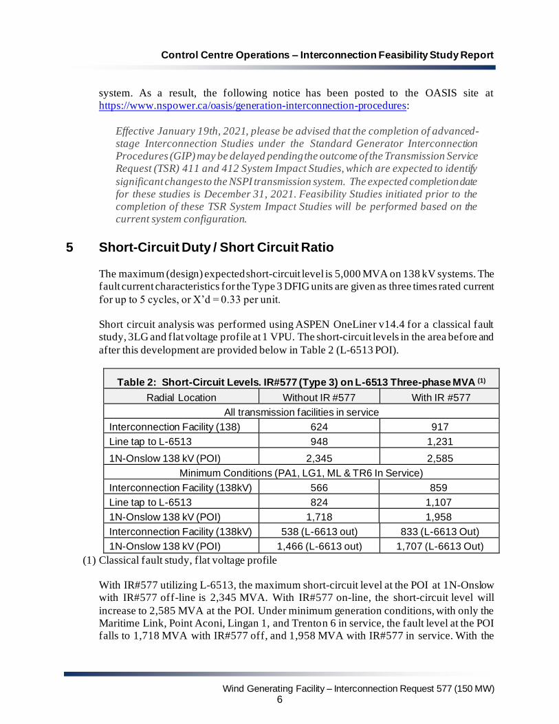
5 Short-Circuit Duty / Short Circuit Ratio
The maximum (design) expected short-circuit level is 5,000 MVA on 138 kV systems. The fault current characteristics for the Type 3 DFIG units are given as three times rated current
for up to 5 cycles, or X’d = 0.33 per unit. Short circuit analysis was performed using ASPEN OneLiner v14.4 for a classical fault study, 3LG and flat voltage profile at 1 VPU. The short-circuit levels in the area before and
after this development are provided below in Table 2 (L-6513 POI).
(1) Classical fault study, flat voltage profile With IR#577 utilizing L-6513, the maximum short-circuit level at the POI at 1N-Onslow with IR#577 off-line is 2,345 MVA. With IR#577 on-line, the short-circuit level will
increase to 2,585 MVA at the POI. Under minimum generation conditions, with only the Maritime Link, Point Aconi, Lingan 1, and Trenton 6 in service, the fault level at the POI falls to 1,718 MVA with IR#577 off, and 1,958 MVA with IR#577 in service. With the
further contingency loss of L-6613 between Onslow and Springhill, the fault level at the POI falls to 1,466 MVA with IR#577 off, and 1,707 MVA with IR#577 in service.
The interrupting capability of the 138 kV circuit breakers at 1N-Onslow is at least 3,500 MVA. As such, the interrupting ratings at this substation will not be exceeded by this development on its own. Therefore IR#577 will not impact the circuit breakers at 1N-Onslow.
Wind generation installations often have a minimum Short Circuit Ratio for proper operation of converters and control circuits. Based on the calculated short circuit levels; the use of L-6513; a POI at 1N-Onslow; and a 150 MW installation consisting of 40 units
each 4.256 MVA, the short circuit ratio would be 3.32 at the HV terminals of the IR#577 substation with all lines in service and IR#577 off line. This falls to 3.16 with L-6613 out of service. If 50 units are installed, these values drop to 2.66 and 2.53 respectively. This information should be provided to GE for design specification.
6 Voltage Flicker and Harmonics
Due to the lack of flicker coefficient information on the GE 3.8-130 Wind Turbines, this study assumed the same flicker data as for the GE 1.6 machine (flicker co-efficient 3.31 at
average wind speed of 7.5m/s and impedance angle of 60 degrees; apparent power of each turbine 4.256MVA). Under these conditions, Pst was calculated to be 0.16, well below the maximum permitted level of 0.35.
Type 3 wind turbines are not expected to result in appreciable voltage flicker at minimum generation conditions. Voltage flicker will be further examined when data for the 3.8MW GE machine is made available for the SIS.
The generator is expected to meet IEEE Standard 519-2014 limiting voltage Total Harmonic Distortion (all frequencies) to a maximum of 1.5%, with no individual harmonic exceeding 1.5% on 138 kV.
7 Thermal Limits
The load flow analysis was completed for generation dispatches under system light load, summer peak load, and winter peak load conditions. Generation dispatch was also chosen to represent import and export scenarios that take into account expected flows from the
existing transmission service reservation associated with the Maritime Link. Transmission connected wind generation facilities were typically dispatched at approximately 40%, with some low and high wind scenarios included. The cases and dispatch scenarios considered are shown in Table 3.
Control Centre Operations – Interconnection Feasibility Study Report
For NRIS analysis, this FEAS added IR#577 and displaced generation south of Onslow,
increasing Onslow South (ONS) transfers. For ERIS analysis, this FEAS displaced generation east of Onslow. This resulted in lower Onslow Import and Cape Breton Export transfers and had no impact on ONS transfer levels. Single contingencies were applied at the 345 kV, 230 kV, and 138 kV voltage levels for the above system conditions with
IR#577 interconnected to the 138kV bus at 1N-Onslow via line L-6513 As previously noted, L-6513 is a 138kV line that runs adjacent to L-6613 between Onslow and Springhill that is no longer in service. L-6513 was built to 138kV standards utilizing
556.5 kcmil ACSR Dove conductor with a design conductor temperature of 50°C. Although the conductor has a thermal design rating of 110 MVA in summer and 165 MVA in winter2, its last Lidar survey indicated that ground clearance had deteriorated over time, and it would need to be upgraded to meet the original design rating of 110 MVA. To
provide capability for 150 MW, it must be further uprated to 70°C.
2Summer rating is based on an ambient temperature of 25°C; winter rating is based on ambient temperature of 5°C.
When ambient temperature exceeds these assumed ambient temperatures, transmission lines may be de-rated.
Control Centre Operations – Interconnection Feasibility Study Report
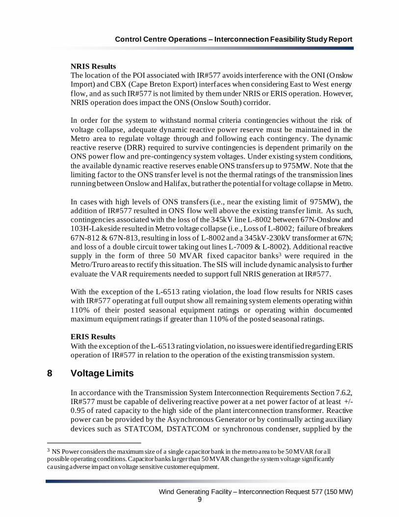
The location of the POI associated with IR#577 avoids interference with the ONI (Onslow Import) and CBX (Cape Breton Export) interfaces when considering East to West energy
flow, and as such IR#577 is not limited by them under NRIS or ERIS operation. However, NRIS operation does impact the ONS (Onslow South) corridor. In order for the system to withstand normal criteria contingencies without the risk of
voltage collapse, adequate dynamic reactive power reserve must be maintained in the Metro area to regulate voltage through and following each contingency. The dynamic reactive reserve (DRR) required to survive contingencies is dependent primarily on the ONS power flow and pre-contingency system voltages. Under existing system conditions,
the available dynamic reactive reserves enable ONS transfers up to 975MW. Note that the limiting factor to the ONS transfer level is not the thermal ratings of the transmission lines running between Onslow and Halifax, but rather the potential for voltage collapse in Metro.
In cases with high levels of ONS transfers (i.e., near the existing limit of 975MW), the addition of IR#577 resulted in ONS flow well above the existing transfer limit. As such, contingencies associated with the loss of the 345kV line L-8002 between 67N-Onslow and 103H-Lakeside resulted in Metro voltage collapse (i.e., Loss of L-8002; failure of breakers
67N-812 & 67N-813, resulting in loss of L-8002 and a 345kV-230kV transformer at 67N; and loss of a double circuit tower taking out lines L-7009 & L-8002). Additional reactive supply in the form of three 50 MVAR fixed capacitor banks3 were required in the Metro/Truro areas to rectify this situation. The SIS will include dynamic analysis to further
evaluate the VAR requirements needed to support full NRIS generation at IR#577. With the exception of the L-6513 rating violation, the load flow results for NRIS cases with IR#577 operating at full output show all remaining system elements operating within
110% of their posted seasonal equipment ratings or operating within documented maximum equipment ratings if greater than 110% of the posted seasonal ratings. ERIS Results
With the exception of the L-6513 rating violation, no issues were identified regarding ERIS operation of IR#577 in relation to the operation of the existing transmission system.
8 Voltage Limits
In accordance with the Transmission System Interconnection Requirements Section 7.6.2, IR#577 must be capable of delivering reactive power at a net power factor of at least +/- 0.95 of rated capacity to the high side of the plant interconnection transformer. Reactive power can be provided by the Asynchronous Generator or by continually acting auxiliary
devices such as STATCOM, DSTATCOM or synchronous condenser, supplied by the
3 NS Power considers the maximum size of a single capacitor bank in the metro area to be 50 MVAR for all possible operating conditions. Capacitor banks larger than 50 MVAR change the system voltage significantly
causing adverse impact on voltage sensitive customer equipment.
Control Centre Operations – Interconnection Feasibility Study Report
Interconnection Customer. Rated reactive power shall be available through the full range of real power output of the Generating Facility, from zero to full power. This translates into a reactive capability of 49 Mvar leading and lagging.
Data provided by the IC indicates that IR#577 may be able to meet this requirement without additional reactive support. The information provided indicated that the GE 3.8-130 WECS have a rated power factor of 0.90 lagging to 0.90 leading at the machine terminals.
However, depending on the characteristics of the collector circuits and given the impedances of the transformers, supplementary reactive support may be needed at the low voltage terminals of the Interconnection Transformer. This will be further investigated in the System Impact Study.
A centralized controller will be required which continuously adjusts individual generator reactive power output within the plant capability limits and regulates the voltage at the 34.5 kV bus voltage. The voltage controls must be responsive to voltage deviations at the terminals of the Interconnection Facility substation; be equipped with a voltage set-point
control; and also have the ability to slowly adjust the set-point over several (5-10) minutes to maintain reactive power within the individual generators capabilities. The details of the specific control features, control strategy and settings will be reviewed and addressed in the SIS, as will the dynamic performance of the generator and its excitation . Line drop
compensation, voltage droop, control of separate switched capacitor banks must be provided. The NSPI System Operator must have manual and remote control of the voltage set-point
and the reactive set-point of this facility to coordinate reactive power dispatch requirements. This facility must also have low voltage ride-through capability as per Appendix G of the
Standard Generator Interconnection and Operating Agreement (GIA). The SIS will state specific options, controls and additional facilities that are required to achieve this.
GE offers an optional WindFree Reactive Power mode feature which provides reactive
power and voltage control down to zero real power operation (low wind). It is recommended that the IC obtain an optional quote for this feature, as it may help to support system voltage and stability during high power transf er levels. The need for this feature will be further examined in the SIS.
9 System Security / Bulk Power Analysis
The 138kV bus at the 1N-Onslow Substation is already part of the Nova Scotia Bulk Power System (BPS). As such, all protection systems associated with the new 138kV breaker
supplying the radial line to Higgins Mountain must comply with NPCC Directory 4 System Protection Criteria.
Control Centre Operations – Interconnection Feasibility Study Report
The 1N-Onslow substation is also currently classified as part of the NERC Bulk Electric System (BES), subject to the applicable NERC Reliability Criteria. As IR#577 has dispersed generation totalling more than 75MVA, Inclusion I4 of the NERC BES
Definition would apply and each generator would be classified as a BES element. The collector systems would not be BES, as only those parts of the IR#577 facility where the aggregation of dispersed generation resources is > 75MVA would be designated as BES. The IR#577 138kV bus would be classified as a BES element, but transformers T61, T62,
and T63 would not as individually they carry < 75MVA of aggregate generation. If the 34.5kV switches between LV bus sections are normally closed, the 34.5kV bus would also be classified as BES.
10 Expected Facilities Required for Interconnection
The following facility changes will be required to connect IR#577 to the NSPI transmission system at 1N-Onslow:
10.1 NRIS:
a. Required Network Upgrades
• Modification of NSPI protection systems at 1N-Onslow.
• Installation of three 50 MVAR fixed capacitor banks in the Metro/Truro areas.
b. Required Transmission Provider’s Interconnection Facilities (TPIF):
• Uprate 30km of transmission line L-6513 between 1N-Onslow and the new 15km line extension to Higgins Mountain to a conductor operating temperature of 70°C.
• Add one new 138kV circuit breaker, associated switches, and 138kV line termination at 1N-Onslow.
• Add control and communications between the wind farm and NSPI SCADA system (to be specified).
• Disconnect the remaining 30km section of L-6513 between the IR#577 tap point and the 74N-Springhill substation.
c. Required Interconnection Customer’s Interconnection Facilities (ICIF)
• The Interconnection Substation will be located at Higgins Mountain, and therefore
a new radial branch line utilizing the first 30km of L-6513 and 15 km of new 138kV, 795 drake transmission line is required. The branch line would be designed for 138 kV and would be shielded for 1 km out of the Interconnection Substation. The branch line would be connected to L-6513 at a point approximately 30km
Control Centre Operations – Interconnection Feasibility Study Report
from 1N-Onslow. The Interconnection Substation would require a main disconnect switch and circuit breakers at high side of each of the customer power transformers and protection as acceptable to NSPI. A Remote Terminal Unit
(RTU) to interface with NSPI’s SCADA, with telemetry and controls as required by NSPI.
• Facilities to provide 0.95 leading and lagging power factor when delivering rated output at the HV terminals of the IC Substation Step Up Transformer when the voltage at that point is operating between 95 and 105 % of nominal. The functionality of the WindFree Reactive Power mode should be considered.
• Centralized controls. These will provide centralized voltage set-point controls and are known as Farm Control Units (FCU). The FCU will control the 34.5 kV bus
voltage and the reactive output of the machines. Responsive (fast-acting) controls are required. The controls will also include a curtailment scheme which will limit or reduce total output from the facility, upon receipt of a telemetered signal from NSPI’s SCADA system.
• NSPI will have control and monitoring of reactive output of this facility, via the
centralized controller. This will permit the NSPI Operator to raise or lower the voltage set-point remotely.
• Low voltage ride-through capability per Section 7.4.1 of the Nova Scotia Power Transmission System Interconnection Requirements (TSIR) document. The TSIR is posted on the NS Power OASIS site at https://www.nspower.ca/oasis/standards-codes.
• Real-time monitoring (including an RTU) of the interconnection facilities. Local wind speed and direction, MW and MVAR, as well as bus voltages are required.
• Facilities for NSPI to execute high speed rejection of generation (transfer trip) if determined in SIS. The plant may be incorporated into SPS run-back schemes.
• Synthesized inertial response controls as offered by GE.
• Automatic Generation Control to assist with tie-line regulation.
• Operation at ambient temperature of -30°C.
10.2 ERIS:
a. ERIS: Required Network Upgrades
1. For ERIS generation, modification of NSPI protection systems at 1N-Onslow
The preliminary non-binding cost estimate for interconnecting 150 MW at the POI at 1N-Onslow under NRIS is $16,967,500 including a contingency of 10% and assuming that NSPI builds the 138 kV spur line. This does not include TBD costs to address any stability
issues identified at the SIS stage based on dynamic analysis.
The preliminary non-binding cost estimate for interconnecting 150 MW at the POI at 1N-Onslow under ERIS is $11,467,500 including a contingency of 10% and assuming that
NSPI builds the 138 kV spur line. This does not include TBD costs to address any stability issues identified at the SIS stage based on dynamic analysis. The estimated time to construct the Transmission providers Interconnection Facilities is
18-24 months after receipt of funds and cleared right of way from the IC.
12 Loss Factor
Loss factor is calculated by running the winter peak load flow case with and without the
new facility in service while keeping 91H-Tufts Cove as the Nova Scotia Area Interchange bus. This methodology reflects the load centre in and around 91H. Without IR#577 in service, losses in the winter peak case total 86.2 MW. With IR#577 in
service displacing generation at 91H, and not including losses associated with the IR#577 Generation Facilities or TPIF Interconnection Facilities, system losses total 92.1 MW, an increase of 5.9 MW. As such, the loss factor for IR#577 is as follows:
5.9 MW / 150 MW x 100% = +3.93%.
13 Issues to be addressed in SIS
The following provides a preliminary scope of work for the subsequent SIS for IR#577.
The SIS will include a more comprehensive assessment of the technical issues and requirements to interconnect generation as requested. It will include contingency analysis, system stability, ride through, and operation following a contingency (N-1 operation). The SIS must determine the facilities required to operate this facility at full capacity, withstand
any contingencies (as defined by the criteria appropriate to the location) and identify any restrictions that must be placed on the system following a first contingency loss. The SIS will confirm the options and ancillary equipment that the customer must install to control flicker, voltage, frequency response, active power and ensure that the facility has the
required ride-through capability. The SIS will be conducted in accordance with the GIP with the assumption that all appropriate higher-queued projects will proceed and the facilities associated with those projects are installed. The following outline provides the minimum scope that must be complete in order to assess
the impacts. It is recognized the actual scope may deviate, to achieve the primary objectives.
Control Centre Operations – Interconnection Feasibility Study Report
Any changes to SPS schemes required for operation of this generating facility, in addition to existing generation and facilities that can proceed before this project, will be determined by the SIS as well as any required additional transmission facilities. The determination will
be based on NERC4 and NPCC5 criteria as well as NSPI guidelines and good utility practice. The SIS will also determine the contingencies for which this facility must be curtailed.
Nova Scotia Power Transmission System Operations 2021-03-04
4 NPCC criteria are set forth in its Reliability Reference Directory #1 Design and Operation of the Bulk Power System 5 NERC transmission criteria are set forth in NERC Reliability Standard TPL-001-4