HNF-3395 Revision 5 Interface Control Document between the 242-A Evaporator Facility and the Liquid Effluent Retention Facility Prepared for the U.S. Department of Energy Assistant Secretary for Environmental Management Contractor for the U.S. Department of Energy under Contract DE-AC06-08RL1 4788 0 C*42MVHILL -4400 Plateau Remediation Company P.O. Box 1600 Richland, Washington 99352 Approved tor Public Release; Further Dissemination Unfirifted
Transcript
HNF-3395Revision 5
Interface ControlDocument between the242-A Evaporator Facilityand the Liquid EffluentRetention Facility
Prepared for the U.S. Department of EnergyAssistant Secretary for Environmental ManagementContractor for the U.S. Department of Energyunder Contract DE-AC06-08RL1 4788
0 C*42MVHILL-4400 Plateau Remediation Company
P.O. Box 1600Richland, Washington 99352
Approved tor Public Release;Further Dissemination Unfirifted
HNF-3395Revision 5
EDO #: ECR-1 0-001701
Interface Control Document betweenthe 242-A Evaporator Facility and theLiquid Effluent Retention Facility
Document Type: lCD Program/Project: WVFMP
J. L. PennockCH2MV HILL Plateau Remediation Company
Date Published
November 2010
Prepared for the U.S. Department of EnergyAssistant Secretary for Environmental ManagementContractor for the U.S. Department of Energyunder Contract DE-ACO6-08RL1 4788
*CH42MVHILLSPlateau Remediation Company
RO. Box 1600Richland, Washington
FDAT (HANFORDOLD
STA. ID:AG
Rfieae Approval DaeRelease Stamp
Approved for Public Release;Further Dissemination Unlimrited
HNF-3395Revision 5
TRADEMARK DISCLAIMERReference herein to any specific commercial product, process,or service by trade name, trademark, manufacturer, orotherwise, does not necessarily constitute or imply itsendorsement, recommendation, or favoring by the UnitedStates Government or any agency thereof or its contractors orsubcontractors.
This report has been reproduced from the best available copy.
Printed in the United States of America
Total Pages: /
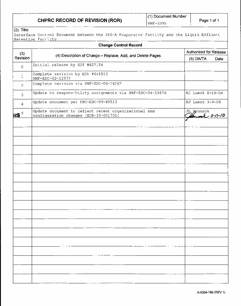
CHPRC RECORD OF REVISION (ROR) (1)Docmen Nube Page 1 of 1
(2) TitleInterface Control Document between the 242-A Evaporator Facility and the Liquid EffluentRetention Facility
Change Control Record
(3) (4 ecito fCag elcAd n eeePgsAuthorized for ReleaseRevision (4 ecito fCag elcAd n eeePgs(5) DA/TA Date
0 Initial release by EDT #627154
1 Complete revision by ECN #6445131 HNF-EDC-02-12572
2 Complete revision via HNF-EDC-03-16267
3 Update to responsibility assignments via HNF-EDC-04-19876 KJ Lueck 8-19-04
4 Update document per PRC-EDC-09-40513 KJ Lueck 3-9-09
RS Update document to reflect recent organizational and JL ? nnockconfiguration changes (ECR-10-001701) 11-17-ID
A-6004-786 (REV 1)
HNF-3395 Rev 5
INTERFACE CONTROL DOCUMENT BETWEENTHE 242-A EVAPORATOR FACILITY AND THE
LIQUID EFFLUENT RETENTION FACILITY
Approved by:
BJ-l. Von Bargen, 242-A Facility Manager Date
Dunning, W0 P ject Contract Manager Date
__ __2_ __ _ ___L_ _ Ic (p/V.L. Wagner, 242-A Opirations STA Date
R.N. Dale, 242-A Engineering Date
_ _ _ _ _ _ _ _/__X_6 //0
D.B. Cartmell, V.P, Business Services and Project Controls Date
1. 1 SYSTEM PURPOSE............................................................................................................. 11.2 SYSTEM OVERVIEW........................................................................................................... 1
Figure 1. Interfaces Responsibilities Between the 242-A Evaporator Facility and LERF......................... 2
HNF-3395 Rev 5
TERMS
CHPRC CH2M HILL Plateau Remediation CompanyDOE U. S. Department of EnergyDST double-shell tankETF Effluent Treatment FacilityICD Interface Control DocumentLDR land disposal restrictionLERF Liquid Effluent Retention FacilityLWFS Liquid Waste and Fuels StorageMOA Memorandum of AgreementORP Office of River ProtectionPC process condensatePCB polychlorinated biphenylsRL Richland Operations OfficeSOM [ETF] Shift Operations ManagerSSC structures, systems and componentsSSM [WRPS] Senior Shift ManagerTSR Technical Safety RequirementsUSQ Unreviewed Safety QuestionWRPS Washington River Protection Solutions, LLCWTP Waste Treatment Plant
HNF-3395 Rev 5
1.0 SCOPE
1.1 SYSTEM PURPOSE
This Interface Control Document (ICD) provides the physical and technical requirements forinterfacing the 242-A Evaporator Facility and the Liquid Effluent Retention Facility (LERF) (seeFigure 1). The 242-A Evaporator is a Hazard Category 2 Nuclear Facility and LERF is a belowHazard Category 3 Nuclear Facility. The ICD identifies requirements and responsibilities,applicable references, acceptance standards, subsystem requirements, and other relevantinformation. The objective of this interface control is to ensure that the technical integrity ofstructures, systems, and components (SSC) at the physical and fuinctional boundaries sharedjointly by two Department of Energy (DOE) Contractors are properly managed.
This ICD has been written in accordance with Washington River Protection Solutions, LLC(WRPS) procedure TFC-BSM-CP-CPR-C- 17, Interface Management, with guidance fromCH2M HILL Plateau Remediation Company (CHPRC) procedure PRC-PRO-MS- 10472,Interface Management. This ICD shall be part of the technical baseline for the 242-AEvaporator Facility and LERF. It is the responsibility of WRPS and CHPRC to ensure that theirrespective sides of the interface are controlled through the identification, preservation, andaccurate dissemination of interface information within their implementing documentation.
This ICD provides the interface requirements for normal process condensate (PC) flows from the242-A Evaporator to LERF and does not encompass accident scenarios. Modifications to thephysical interface of SSCs between WRPS and CHPRC are maintained under configurationcontrol as discussed in this ICD. The nonradioactive, nonhazardous wastewater discharges fromthe 242-A Evaporator facilities to the 200 Area Treated Effluent Disposal Facility are coveredunder a separate ICD (HNF-SD-W049H-ICD-00 1).
1.2 SYSTEM OVERVIEW
The 242-A Evaporator is operated by WRPS for the DOE, Office of River Protection (ORP); theapplicable oversight organization being Base Operations. CHPRC operates the LERF for theDOE, Richland Operations Office (RL); the applicable oversight organization being the LiquidWaste and Fuels Storage (LWFS) organization. The 242-A Evaporator concentrates liquid wastefrom the Double Shell Tanks (DST) and returns the concentrated slurry back to the DSTs. PCfrom the 242-A Evaporator discharges to LERF.
H-NF-3395 Rev 5
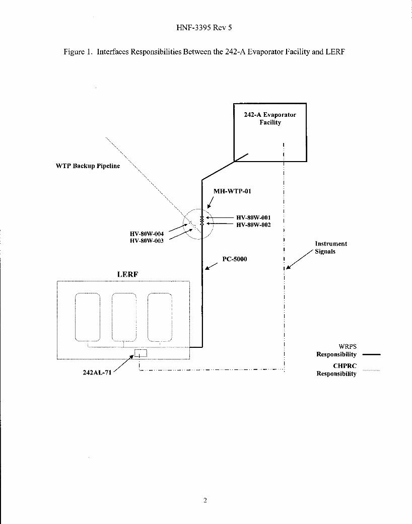
Figure 1. Interfaces Responsibilities Between the 242-A Evaporator Facility and LERF
242-A EvaporatorFacility
WTP Backup Pipeline
MH-WTP-01
.- .......... O.4- HV-80W-002
IIV-80W-0042
HV-80-003InstrumentISignals
PC-5000I
LERF
I Responsibility -
CHPRC242AL-71 Responsibility
2
HNF-3395 Rev 5
2.0 RESPONSIBILITIES/REQUIREMENTS
The 242-A Evaporator is a Hazard Category 2 Nuclear Facility and LERF is a below HazardCategory 3 Nuclear Facility. They present substantial responsibilities to the operatingcontractors, and because of their physical interface there is ample opportunity for one system toadversely impact the safe and efficient operation of the other. The responsibilities andrequirements for each contractor to ensure that the 242-A Evaporator and LERF are operated andmaintained within their safety bases are provided in Sections 3.2 through 3.4.
This lCD is subordinate to the current respective Prime Contracts and the Memorandum ofAgreement (MOA) Number MOA-WRPS-CHPRC-2009, Rev. 2, Memorandum ofAgreementfor the Performance and Payment of Services, between WRPS and CHPRC. The terms andconditions contained in the prime contracts and other agreements applicable to the respectiveparties shall prevail over any conflicts and conflicting termns and conditions herein.
Receipt, storage and treatment of 242-A Evaporator PC at the LERF and Effluent TreatmentFacility (ETF) are provided by CHPRC to WRPS at no cost as delineated in Attachment J-3,Hanford Site Services and Interface Requirements Matrix, contained in the WRPS TankOperations Contract, Number DE-AC27-08RV14800, and the CHPRC Plateau RemediationContract, Number DE-A C06-O8RLJ 4788.
3.0 INTERFACE INFORMATION
3.1 PHYSICAL INTERFACES
The interfaces between the 242-A Evaporator Facility and LERF are defined as follows (seeFigure 1):
LERF consists of three lined surface impoundments, or basins. The LERF receives PC fromthe 242-A Evaporator through a dedicated pipeline, PC-5000. The interface point of thePC-5000 pipeline is the LERF fence line. WRPS is responsible for the PC-5000 pipelineup to the LERF fence, including isolation valves HV-80W-OO1 and HV-80W-002.WRPS will also be responsible for the entire electronic leak detection system (leaksensors, cabling, leak detection module, and collection tank 60M-TK-1) on this PC-5000pipeline. CHPRC will be responsible for the wiring between the PC-5000 leak detectionmodule and the LERF control system. WRPS is responsible to maintain hardware,software and controls at the 242-A Evaporator necessary to prevent the accidentaldischarge of material to LERF. CHPRC is responsible to maintain instruments,hardware, and software in the LERF control system to communicate necessary LERFsignals and PC-5000 electronic leak detection signals to the 242-A Evaporator.
Waste Treatment Plant (WTP) backup line to the LERF ties into the PC-5000 pipeline atmanhole MH-WTP-O 1. The WTP backup line and Manhole MH-WTP-O 1 will remainthe responsibility of CHPRC, along with isolation valves HV-80W-003 and HV-80W-004. Physical access control to the isolation valves is described in Section 3.2. 1.
3.2 ADMINISTRATIVE INTERFACES
To ensure effective communication, single points of contact have been established. For WRPSthe single point of contact with the LERF is the ETF Shift Operations Manager (SOM). For
3
HNF-3395 Rev 5
CHPRC, the single point of contact with the 242-A Evaporator is the 242-A Evaporator SeniorShift Manager (SSM), or designated alternate.
3.2.1 Work Control
L WFS
1 . Notify 242-A Control Room Operator upon entering and exiting the 242-A EvaporatorFacility.
2. Notify 242-A Control Room Operator when accessing manhole MH-WTP-Ol.
3. Notify 242-A Evaporator SSM and obtain approval of any operation or maintenancework having the potential to impact 242-A Evaporator equipment or systems one workingday in advance.
- Perform energy control (i.e., lock and tag) as follows: LWFS Operations performns"first on/last off' lock and tag of all equipment inside the LERF fence, regardless ofequipment ownership or work initiator. Base Operations may choose to overtag oruse administrative locks on the equipment after notifying the ETF SOM. All LWFSlock and tags performed in the LERF must comply with DOE-03 36, Hanford SiteLockout/Tagout.
- LWFS notifies 242-A Evaporator SSM if performing lock and tag on equipment inthe 242-A Evaporator Facility or isolation valves in MH-WTP-Ol. Any potentialimpacts to 242-A Evaporator equipment or processes shall be evaluated andunderstood, prior to lock and tag of equipment, between the Base OperationsEngineering and LWFS Engineering. All lock and tags performned in the 242-AEvaporator Facility must comply with DOE-03 36, Hanford Site Lockout/Tagout.
- 242-A Evaporator Operations performs "first on/last off' lock and tag of all 242-AEvaporator equipment, including isolation valves HV-80W-OO1 and HV-80W-002.LWFS Operations may choose to overtag the equipment after notifying 242-AEvaporator SSM with either a Controlling Organization lock and tag or by anAuthorized workers lock.
Base Operations
1 . Obtain ETF Control Room approval before accessing manhole MH-WTP-0l and before
entry within the LERF fence.
2. Perform maintenance work on PC-5000 equipment up to the LERF fence and any BaseOperations equipment inside the LERF fence.
3. Receive permission from ETF SOM before performing maintenance work on 242-AEvaporator System equipment located inside the LERF fence. Provide documentation toETF SOM of work that has been released.
4. Perform energy control (i.e., lock and tag) as described under LWFS responsibilitiesabove. All Base Operations Controlling Organization lock and tag will be administeredin accordance with the current revision of DOE-03 3 6, Hanford Site Lockout/Tagout.
4
HNF-3 395 Rev 5
3.2.2 Communications
The 242-A PC often contains constituents which exceed their land disposal restriction (LDR)levels in 40 CFR 268. Surface impoundments such as LERF cannot accept such wastes withoutan exemption that requires annual removal of wastes which exceed LDR treatment standards.To address the conditions of this exemption, LWFS: 1) prohibits solids from transferring toLERF and 2) removes basin supernate (i.e., liquid component) provided the basin inventory stillexceeds LDR treatment standards.
Base Operations shall identify on the waste profile sheet (Section 3.3.2) constituents andtreatment standards applicable to the PC prior to a campaign with confirmatory samplingperformed during the campaign. To ensure no solids are sent to LERF, PC shall be filteredthrough a 5-micron (nominal) filter, as required by the LWFS waste acceptance criteria (1-NF-3172) or sampled weekly to verify no suspended solids are present (95-LEP-0 1 5)(Section 3.4).
Coordination is required to allow LWFS to comply with the annual removal requirement of theLERF exemption. Typically, PC is segregated from other wastewaters in LERF because itcontains ammonia. At this time, only one basin is available to receive PC. If the basin receivingPC must be emptied because it exceeds an LDR treatment standard, WRPS must shutdowntransfers to LERF for a minimum of 60 days annually so that LWFS can process that basin downto the 3 -foot level. These 60 days can be in one window or two 30 day windows.
L WFS
I. Provide an annual forecast of ETF campaigns and LERF activities which would affecttransfers of PC to LERF, with monthly updates.
2. Contact the 242-A Evaporator SSM for day-to-day issues (coordinating outages, etc.).Requests for operational support should be made 24 hours in advance, if possible, toensure adequate coverage could be made available.
3. Notify 242-A Evaporator SSM of any change in physical connections to or valveconfiguration of the PC-5000 pipeline.
Base Operations
1 . Provide annual forecast of 242-A Evaporator campaigns including both scheduledcampaign date and projected volume, with monthly updates.
2. Communicate directly with the ETF SOM for status of operations during evaporatorcampaigns. Report to the ETF Control Room daily volume transfer of PC to LERF duringcampaigns.
3. Communicate directly with ETF SOM for day-to-day issues requiring interface with 242-A Evaporator Facility and LERF.
4. Notify ETF SOM of any physical modification to the 242-A Evaporator PC dischargesystem.
HNF-3395 Rev 5
3.2.3 Alarm Response
L WFS
1 . All LERE related alarms at ETF also alarm at 242-A, so no CHPRC specific actions arerequired to notify WRPS of these alarms.
2. Notify the Base Operations at least one day prior to performing scheduled upgrades ormaintenance work activities that could potentially activate LERF alarms in the 242-AEvaporator Facility and/or adversely impact scheduled evaporator operations.
3. Provide access to the LERF Basins for troubleshooting of the electronic PC-5000 leakdetection system/alarms and/or alternative electronic PC-5 000 leak detection monitoring.
Base Operations
1. Maintain electronic leak detection on PC-5 000 pipeline or implement approvedequivalent leak detection monitoring. Respond to alarms per facility Alarm ResponseProcedure and notify ETF Control Room of alarm.
3.2.4 Safety Basis
L WFS
The LERF is designated as a below Hazard Category 3 Nuclear Facility. The PC-5000 pipelineis currently in the scope of the LERF safety basis and is included in the 242-A EvaporatorDocumented Safety Analysis (HNF-1475 5). The 242-A Evaporator PC accepted at LERF willbe controlled so that the wastewater dose consequence does not exceed that of the maximumbounding radiological source term evaluated in the Liquid Effluent Retention Facility FinalHazard Category Determination (HNF-SD-WM-SAD-040). The LERF is also designated as acriticality exempt facility and must stay below 15 grams of total fissile material. Theradiological source term and criticality requirements are addressed in the LWFS wasteacceptance criteria (HNF-3 172). LWFS uses the data from the waste profile provided by BaseOperations (Section 3.3.2) to confirm compliance.
Base Operations
Base Operations has procedures (TFC-ENG-SB-C-0 1, Safety Basis Issuance and Maintenance,and TFC-ENG-SB-C-03, Unreviewed Safety Question Process) in place to evaluate proposedchanges and discoveries with respect to potential impact to the Safety Basis. The 242-AEvaporator Documented Safety Analysis requires that the Evaporator Technical SafetyRequirements (TSR) remain compatible with the TSRs of interfacing facilities. The UnreviewedSafety Question (USQ) processes at the 242-A Evaporator and this LCD will be used to ensurecontinued compatibility of safety bases. A modification to an interfacing structure, system,and/or component between WRPS and CHPRC is not allowed without USQ evaluation inaccordance with WRPS procedure TFC-ENG-SB-C-03.
The safety basis for the 242-A Evaporator is documented in:
1. LWFS does not have any sampling and sample delivery responsibilities within the scopeof this ICD.
Base Operations
1 . Sample and analyze 242-A Evaporator discharges to LERF during a 242-A Evaporatorcampaign per the LWFS waste acceptance criteria (H-NF-3 172). In addition, the PC mustbe sampled for polychlorinated biphenyls (PCBs).
2. Ensure hard and electronic copies of the summary data package for 242-A Evaporatordischarges are provided to LWFS within 45 days of campaign completion.
3.3.2 Waste Acceptance
Discharges to LERF must meet the LWFS waste acceptance criteria (I-NF-3 172).
L WFS
1. Perform a waste acceptance assessment for authorization of 242-A Evaporator dischargesto LERF. The waste acceptance assessment shall be completed within 14 days of receiptof certified waste profile sheet submitted by WRPS.
Base Operations
1 . Submit a certified waste profile per the LWFS waste acceptance criteria (HNF-3 172) for242-A Evaporator discharges to LERF, 30 days prior to the start of a 242-A Evaporatorcampaign. The waste profile must include calculated PC concentrations and a list ofconstituents which may exceed LDR treatment standards. A projection based on BaseOperations feed tank data can be used for the required PC waste profile.
3.4 TRANSFERS
LWFS must manage LERF volumes to minimize impact to customers that transfer wastewater toLERF, allow time for ETF to process wastewater stored in LERF, and meet requirements forLERF clean-out and contingency space. To do this, WRPS must provide LWFS with updatedannual forecasts of PC volumes and scheduled dates of 242-A Evaporator campaigns. LWFSwill use the forecasts to communicate to WRPS the LERF volume available to for PC, based onprioritizing the need of all LWFS customers.
L WFS
1. Maintain capability for receiving 242-A Evaporator PC, as described above, except underthose conditions addressed in Section 3.2.2, at a nominal flow rate of 50 gallons perminute.
7
HNF-3395 Rev 5
Base Operations
1. Obtain approval from LWFS to discharge 242-A Evaporator effluent to LERE.
2. Ensure all PC and other solutions sent to LERF contain no solids by either transferringthem through a 5-micron (nominal) filter or performing weekly sampling and analyses toconfirm no total suspended solids are present.
4.0 CONFIGURATION MANAGEMENT
This ICD will be maintained under configuration control. The signatures on the cover page ofthis document indicate agreement between WRPS and CHPRC that this document reflects thecurrent technical baseline for each system and that the responsibilities and requirementscontained in this document will not be revised without the agreement of all parties.
Approved and released implementing design documentation that includes the physical interfaceof SSCs between WRPS and CHPRC is maintained under configuration control. Modificationsmade by CHPRC for change approval by WRPS on interfacing SSCs shall be documented usingthe CHPRC Facility Modification Package Process, PRC-PRO-EN-2001. Modification made byWRPS for change approval by CHPRC on interfacing SSCs shall be documented using a formatsimilar to the "Interface Change" form (Site Form #A-6002-985). CHPRC shall contact the 242-A Evaporator SSM for request of WRPS approval on modification and conversely, WRPS shallcontact the ETF SOM for approval on modifications. The Contractor requesting approval formodification of SSCs shall allow for a two-week turnaround, unless a shorter duration is agreedupon.
5.0 ISSUES
This section includes items that require resolution for either of the parties to meet theirresponsibilities.
5.1 OPEN ISSUES
This section contains only current issues and does not carry over issues from previous revisionsthat no longer apply.
5. 1.1 Waste Treatment Plant Backup Line
The WTP backup line to the LERF ties into PC-5000 pipeline at manhole MH-WTP-01 (seeFigure 1), however, this line is currently capped and WTP has yet to make their connection to theCHPRC portion of the WTP backup line. Once the tie-in has been completed CHPRC andWRPS will need to update ICD 24590-WTP-ICD-MG-O1, ICD-06 - Interface Control Documentfor Radioactive, Dangerous Waste Liquid Effluent, and coordinate the use of the backup line forthe hydrotest.
6.0 ACCEPTANCE METHODS AND STANDARDS
See Sections 3.3.1 through 3.4 for operational acceptance criteria for waste streams.
8
HNF-3395 Rev 5
7.0 REFERENCES
24590-WTP-TCD-MG- 1 -006, lCD 06 - Interface Control Document for Radioactive,Dangerous Liquid Effluents, Rev. 4, River Protection Project, Richland, Washington.
95-LEP-0O15, letter dated 04/25/95, Liquid Effluent Retention Facility (LERF) TreatmentExemption, T.K. Teynor (DOE-RI) to D.R. Sherwood (EPA), U.S. Department ofEnergy, Richland Operations Office, Richiland, Washington.
DOE-0336, Hanford Site Lockout/Tagout, as amended, U.S. Department of Energy, Richland,Washington.