INVESTIGACI ´ ON REVISTA MEXICANA DE F ´ ISICA 51 (6) 591–595 DICIEMBRE 2005 Interferometric sinograms of transparent objects with stepping wise shifted Ronchi ruling for optical tomography C. Meneses-Fabian and G. Rodriguez-Zurita Benem´ erita Universidad Aut´ onoma de Puebla, Facultad de Ciencias F´ ısico-Matem´ aticas, Apartado Postal 1152, Puebla, PUE 72000, M´ exico V. Arriz´ on Instituto Nacional de Astrof´ ısica, ´ Optica y Electr ´ onica, Apartado Postal 51 y 216, Tonantzintla, Puebla PUE 72000, M´ exico Recibido el 21 de enero de 2005; aceptado el 28 de septiembre de 2005 An experimental set-up to achieve tomographic images of slices belonging to transparent objects is presented. The proposed system is based on an interferometer which employs two windows in the object plane and a translating absorptive grating (Ronchi ruling) in the frequency plane. In the image plane, replicated windows can be brought to superposition by proper adjustment of the windows’ spacing and the grating period. After adaptation of this interferometer to tomographic measurements, the phase of the projections result encoded as interference fringes, thereby forming a composite interference pattern in the plane of the corresponding sinogram (interfero-sinograms). Using phase-stepping techniques, four phase-shifted interfero-sinograms are found after proper translation of the grating. Then wrapped a and unwrapped phase is extracted as a conventional interferogram to obtain a sinogram to be subjected to a filtered backprojection algorithm for reconstruction. As experimental results, the reconstructions of some transparent samples are presented. Keywords: Image reconstruction; tomography; interferometers; Fourier optics. Se presenta un arreglo experimental interferom´ etrico para obtener im´ agenes tomogr´ aficas de cortes en objetos transparentes. El sistema propuesto se basa en un interfer´ ometro que emplea dos ventanas en el plano objeto y una rejilla de absorci´ on (rejilla de Ronchi) en el plano de las frecuencias espaciales, capaz de ser trasladada transversalmente. En el plano de la imagen, las ventanas reproducidas en copia pueden superponerse si se elige adecuadamente su espaciamiento respecto al per´ ıodo de la rejilla. Tras adaptar este interfer´ ometro para realizar mediciones tomogr´ aficas, la fase de las proyecciones resulta codificada en franjas de interferencia, formando un interferograma en el plano del senograma (interfero-senograma). Usando t´ ecnicas de corrimiento de fase aplicadas a interfero-senogramas con corrimientos de fase inducidos por translaciones de la rejilla realizados por etapas, las fases envuelta y desenvuelta pueden ser extra´ ıdas para formar un senograma convencional. Este senograma se utiliza para reconstruir la secci´ on mediante un algoritmo estandarizado de retroproyecci´ on filtrada. Se muestran algunas reconstrucciones de varias muestras transparentes. Descriptores: Reconstrucci´ on de im´ agenes; tomograf´ ıa; interferometr´ ıa; ´ optica de Fourier. PACS: 42.30.Wb; 07.60.Ly; 42.30.Kq 1. Introduction A description of the image-formation process of a novel common-path interferometer has been recently presented, us- ing a grating as a spatial filter and two windows at the object plane. In the image plane, superposition of replicated win- dows and their interference can be achieved by the proper choice of the spacing between windows with respect to the grating period. Furthermore, grating displacement enables the introduction of phase values into diffraction orders as de- sired, thereby offering the possibility of shifting interference patterns [1]. This device has resemblances with well-known phase-shift methods using grating displacements [2,3], which have been used as phase shifters in phase-shifting interfer- ometers [2]. In fact, a phase-shifting Schlieren technique us- ing a sinusoidal grating has been reported recently [4]. In this type of grating interferometers, a grating is placed as a spatial filter and the phase changes needed for phase-shifting interferometry can be easily performed with the help of an actuator or with a programmable wave modulator such as a liquid crystal display. Because this kind of interferometers seems to have some practical advantages (such as good sta- bility and a relative ease in introducing phase steps), it might be worthwhile to use them in an optical tomographic sys- tem for imaging phase distributions. In optical tomography, on the other hand, the phase changes which an optical beam accumulates along its path across a given object has to be measured in order to obtain the phase distribution of a cer- tain object slice by reconstruction techniques [5]. Parallel projection tomography for phase objects in the visible range has been reported using liquid gates to attain low refraction conditions [6]. In this communication, we report experimen- tal tomographic reconstructions of some transparent samples using the implementation of a tomographic system equipped with an interferometer which follows as a variant of the one described in Ref. 1. 2. Overlapping of replicated images with a Ronchi ruling For a Ronchi ruling of spatial period d = λf/X 0 , with light bar spatial width given by A w = λfa w and displaced by an amount u 0 = λfμ 0 (1/X 0 , a w , and μ 0 are conjugate vari- ables of d, A w and u 0 in an optical Fourier system, respec-
Transcript
INVESTIGACION REVISTA MEXICANA DE FISICA 51 (6) 591–595 DICIEMBRE 2005
Interferometric sinograms of transparent objects with stepping wise shiftedRonchi ruling for optical tomography
C. Meneses-Fabian and G. Rodriguez-ZuritaBenemerita Universidad Autonoma de Puebla, Facultad de Ciencias Fısico-Matematicas,
Apartado Postal 1152, Puebla, PUE 72000, Mexico
V. ArrizonInstituto Nacional de Astrofısica,Optica y Electronica,
Apartado Postal 51 y 216, Tonantzintla, Puebla PUE 72000, Mexico
Recibido el 21 de enero de 2005; aceptado el 28 de septiembre de 2005
An experimental set-up to achieve tomographic images of slices belonging to transparent objects is presented. The proposed system isbased on an interferometer which employs two windows in the object plane and a translating absorptive grating (Ronchi ruling) in thefrequency plane. In the image plane, replicated windows can be brought to superposition by proper adjustment of the windows’ spacingand the grating period. After adaptation of this interferometer to tomographic measurements, the phase of the projections result encodedas interference fringes, thereby forming a composite interference pattern in the plane of the corresponding sinogram (interfero-sinograms).Using phase-stepping techniques, four phase-shifted interfero-sinograms are found after proper translation of the grating. Then wrapped aand unwrapped phase is extracted as a conventional interferogram to obtain a sinogram to be subjected to a filtered backprojection algorithmfor reconstruction. As experimental results, the reconstructions of some transparent samples are presented.
Se presenta un arreglo experimental interferometrico para obtener imagenes tomograficas de cortes en objetos transparentes. El sistemapropuesto se basa en un interferometro que emplea dos ventanas en el plano objeto y una rejilla de absorcion (rejilla de Ronchi) en elplano de las frecuencias espaciales, capaz de ser trasladada transversalmente. En el plano de la imagen, las ventanas reproducidas en copiapueden superponerse si se elige adecuadamente su espaciamiento respecto al perıodo de la rejilla. Tras adaptar este interferometro pararealizar mediciones tomograficas, la fase de las proyecciones resulta codificada en franjas de interferencia, formando un interferograma enel plano del senograma (interfero-senograma). Usando tecnicas de corrimiento de fase aplicadas a interfero-senogramas con corrimientosde fase inducidos por translaciones de la rejilla realizados por etapas, las fases envuelta y desenvuelta pueden ser extraıdas para formarun senograma convencional. Este senograma se utiliza para reconstruir la seccion mediante un algoritmo estandarizado de retroproyeccionfiltrada. Se muestran algunas reconstrucciones de varias muestras transparentes.
Descriptores:Reconstruccion de imagenes; tomografıa; interferometrıa; optica de Fourier.
PACS: 42.30.Wb; 07.60.Ly; 42.30.Kq
1. Introduction
A description of the image-formation process of a novelcommon-path interferometer has been recently presented, us-ing a grating as a spatial filter and two windows at the objectplane. In the image plane, superposition of replicated win-dows and their interference can be achieved by the properchoice of the spacing between windows with respect to thegrating period. Furthermore, grating displacement enablesthe introduction of phase values into diffraction orders as de-sired, thereby offering the possibility of shifting interferencepatterns [1]. This device has resemblances with well-knownphase-shift methods using grating displacements [2,3], whichhave been used as phase shifters in phase-shifting interfer-ometers [2]. In fact, a phase-shifting Schlieren technique us-ing a sinusoidal grating has been reported recently [4]. Inthis type of grating interferometers, a grating is placed as aspatial filter and the phase changes needed for phase-shiftinginterferometry can be easily performed with the help of anactuator or with a programmable wave modulator such as aliquid crystal display. Because this kind of interferometersseems to have some practical advantages (such as good sta-
bility and a relative ease in introducing phase steps), it mightbe worthwhile to use them in an optical tomographic sys-tem for imaging phase distributions. In optical tomography,on the other hand, the phase changes which an optical beamaccumulates along its path across a given object has to bemeasured in order to obtain the phase distribution of a cer-tain object slice by reconstruction techniques [5]. Parallelprojection tomography for phase objects in the visible rangehas been reported using liquid gates to attain low refractionconditions [6]. In this communication, we report experimen-tal tomographic reconstructions of some transparent samplesusing the implementation of a tomographic system equippedwith an interferometer which follows as a variant of the onedescribed in Ref. 1.
2. Overlapping of replicated images with aRonchi ruling
For a Ronchi ruling of spatial periodd = λf/X0, with lightbar spatial width given byAw = λfaw and displaced by anamountu0 = λfµ0 (1/X0, aw, andµ0 are conjugate vari-ables ofd, Aw andu0 in an optical Fourier system, respec-
592 C. MENESES-FABIAN, G. RODRIGUEZ-ZURITA, AND V. ARRIZON
tively) its transmittance can be written in terms of spatial fre-quencies coordinates as
F (µ, ζ) = rect
(µ
aw
)∗
∞∑n=−∞
δ (µ− µ0 − n/X0), (1)
whereµ = u/λf, ζ = ν/λf , with u, v the actual coordinatesof the Fourier plane,λ the wavelength of the illuminating op-tical beam,f the focal length of each Fourier transform lensof the telecentric system, and the symbol∗ denoting convolu-tion. If the imaging system has the Ronchi ruling as its pupilfunction, the corresponding impulse response can be writtenas the following:
F (x, y) = =−1{F (µ, ζ)} = aw ·X0sinc(awx)
· exp {i2πµ0x}∞∑
n=−∞δ(x− nX0, y). (2)
This expression reduces to
F (x, y) = aw ·X0
∞∑n=−∞
exp {i2π · nµ0X0}
·sinc(nawX0) · δ(x− nX0, y) (3)
for the case of a ruling with equal widths in clear and darkbars,aw = 1/(2X0) and there will be no even diffractionorders (missing orders of order 2). Because the ruling usedin the experiments had not exactly equal widths in light anddark bars, there are no missing orders. The transmittance oftwo windows separated from each other byx0 in the objectplane (Fig. 1a) is given by
t(x, y) = w(x +12x0, y) + w(x− 1
2x0, y)
· exp[iϕ(x− 1
2x0, y)
], (4)
wherew (x, y) = rect (x/a) rect (y/b) is the input windowsystem, andϕ (x, y) is the phase term associated with theprobe wave window, so that the corresponding amplitude inthe image plane can be determined by
tf (x, y) = t(x, y) ∗ F (x, y),
which gives
tf (x, y) = awX0
∞∑n=−∞
exp {i2π · nµ0X0}
· sinc(nawX0) · [w(x +12x0 − nX0, y)
+ w(x− 12x0 − nX0, y)
· exp{iϕ(x− 12x0 − nX0, y)}] (5)
FIGURE 1. Experimental set-up. a) Windows pair.
Thus, in the image plane there are two symmetrically dis-placed ruling with diffraction orders replicating either onewindow or the other. The condition for overlapping ordersn andn + N is NX0 = x0, whereN is an integer. A usefulcase of overlapping replicated windows is the caseN = 2,as shown in Ref. 1 for cosinusoidal absorptive gratings andphase gratings: overlapping occurs for terms with ordersn = +1 andn = −1. Another case of interest isN = 1,in which overlapping occurs for the terms withn = ±1 andn = 0. In this case, each term adopts the following formrespectively:
t0f (x, y) = awx0 · [w(x +12x0, y)
+ w(x− 12x0, y) · exp{iϕ(x− 1
2x0, y)}], (6)
t+1f (x, y) = awx0 exp{i2π · µ0x0} · sinc(awx0)
· [w(x− 12x0, y) + w(x− 3
2x0, y)
· exp{iϕ(x− 32x0, y)}], (7)
and
t−1f (x, y) = awx0 exp{−i2π · µ0x0} · sinc(awx0)
·[w(x +32x0, y) + w(x +
12x0, y)
· exp{iϕ(x +12x0, y)}]. (8)
Then, there are overlapping of contributions of replicatedwindows at each diffraction order. Considering the overlap-ping of the pair of orders 0,1 or 0,-1 without the further con-tribution of replicated windows of a higher order, there wouldbe two-beam interference patterns at points(±x0/2, 0).
Rev. Mex. Fıs. 51 (6) (2005) 591–595
INTERFEROMETRIC SINOGRAMS OF TRANSPARENT OBJECTS WITH STEPPING WISE SHIFTED RONCHI RULING. . . 593
Within the window region of widthw (x− x0/2, y), the ir-radiance for orders 0 and +1 to be consider can be expressedonly as|t0f (x, y) + t+1f (x, y)|2, and more explicitly, it canbe given by
I01 (x, y) = 1 + sinc2 (awx0) + 2sinc(awx0)
× cos [ϕ (x, y) + 2πµ0x0] (9)
and similarly for 0 and -1. The introduction of a phase stepcan be performed with the displacement of an amountµ0.The fringe visibility of these patterns is not unity. It is givenby the following function ofaw
V01 (aw) =2 · sinc(awx0)
1 + sinc2 (awx0), (10)
whose value for the superposition of orders 0 and 1, when
aw = 1/(2x0),
is about 0.91. Under experimental conditions, a fringe con-trast good enough for measurements was found.
3. Experimental set-up
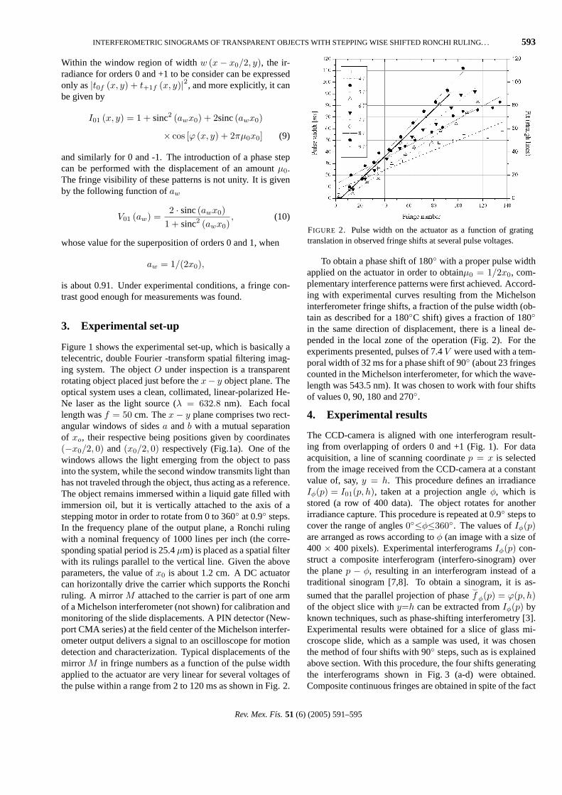
Figure 1 shows the experimental set-up, which is basically atelecentric, double Fourier -transform spatial filtering imag-ing system. The objectO under inspection is a transparentrotating object placed just before thex− y object plane. Theoptical system uses a clean, collimated, linear-polarized He-Ne laser as the light source (λ = 632.8 nm). Each focallength wasf = 50 cm. Thex− y plane comprises two rect-angular windows of sidesa andb with a mutual separationof xo, their respective being positions given by coordinates(−x0/2, 0) and (x0/2, 0) respectively (Fig.1a). One of thewindows allows the light emerging from the object to passinto the system, while the second window transmits light thanhas not traveled through the object, thus acting as a reference.The object remains immersed within a liquid gate filled withimmersion oil, but it is vertically attached to the axis of astepping motor in order to rotate from 0 to 360◦ at 0.9◦ steps.In the frequency plane of the output plane, a Ronchi rulingwith a nominal frequency of 1000 lines per inch (the corre-sponding spatial period is 25.4µm) is placed as a spatial filterwith its rulings parallel to the vertical line. Given the aboveparameters, the value ofx0 is about 1.2 cm. A DC actuatorcan horizontally drive the carrier which supports the Ronchiruling. A mirror M attached to the carrier is part of one armof a Michelson interferometer (not shown) for calibration andmonitoring of the slide displacements. A PIN detector (New-port CMA series) at the field center of the Michelson interfer-ometer output delivers a signal to an oscilloscope for motiondetection and characterization. Typical displacements of themirror M in fringe numbers as a function of the pulse widthapplied to the actuator are very linear for several voltages ofthe pulse within a range from 2 to 120 ms as shown in Fig. 2.
FIGURE 2. Pulse width on the actuator as a function of gratingtranslation in observed fringe shifts at several pulse voltages.
To obtain a phase shift of 180◦ with a proper pulse widthapplied on the actuator in order to obtainµ0 = 1/2x0, com-plementary interference patterns were first achieved. Accord-ing with experimental curves resulting from the Michelsoninterferometer fringe shifts, a fraction of the pulse width (ob-tain as described for a 180◦C shift) gives a fraction of 180◦
in the same direction of displacement, there is a lineal de-pended in the local zone of the operation (Fig. 2). For theexperiments presented, pulses of 7.4V were used with a tem-poral width of 32 ms for a phase shift of 90◦ (about 23 fringescounted in the Michelson interferometer, for which the wave-length was 543.5 nm). It was chosen to work with four shiftsof values 0, 90, 180 and 270◦.
4. Experimental results
The CCD-camera is aligned with one interferogram result-ing from overlapping of orders 0 and +1 (Fig. 1). For dataacquisition, a line of scanning coordinatep = x is selectedfrom the image received from the CCD-camera at a constantvalue of, say,y = h. This procedure defines an irradianceIφ(p) = I01(p, h), taken at a projection angleφ, which isstored (a row of 400 data). The object rotates for anotherirradiance capture. This procedure is repeated at 0.9◦ steps tocover the range of angles0◦≤φ≤360◦. The values ofIφ(p)are arranged as rows according toφ (an image with a size of400× 400 pixels). Experimental interferogramsIφ(p) con-struct a composite interferogram (interfero-sinogram) overthe planep − φ, resulting in an interferogram instead of atraditional sinogram [7,8]. To obtain a sinogram, it is as-
sumed that the parallel projection of phase^
f φ(p) = ϕ(p, h)of the object slice withy=h can be extracted fromIφ(p) byknown techniques, such as phase-shifting interferometry [3].Experimental results were obtained for a slice of glass mi-croscope slide, which as a sample was used, it was chosenthe method of four shifts with 90◦ steps, such as is explainedabove section. With this procedure, the four shifts generatingthe interferograms shown in Fig. 3 (a-d) were obtained.Composite continuous fringes are obtained in spite of the fact
Rev. Mex. Fıs. 51 (6) (2005) 591–595
594 C. MENESES-FABIAN, G. RODRIGUEZ-ZURITA, AND V. ARRIZON
FIGURE 3. (a)-(d)Iφ (p) = I01 (p, h) as functions ofp (horizontalaxis) andφ (vertical axis) as constructed from phase-shifted inter-ferograms. They are referred to as interfero-sinograms. The objectis a microscope slice. (e) Wrapped phase, (f) unwrapped phase, onthe samep-φ plane. (g) and (h) reconstructed object, level gray andthree-dimensional plots, respectively.
that each row has been taken separately. Note that the sym-metry aboutφ = 180◦ is to be recognized with enough ap-proximation. There are also continuous fringes of low fre-quency even in the background. Also, the induced phase stepshifts the fringes in the sinogram plane as a whole. For eachphase-shift, a complete turn of the object had to be made, butthe uncertainty in the reproducibility of the zero position ofthe stepping motor after a complete turn does not appreciablyaffect the composite interferograms. The interference-fringefrequencies change on a very wide range. In particular, theborders of the object generate the highest frequency fringevalues.
In the lower row of Fig. 3, the wrapped phase is firstshown as obtained with a standard phase-stepping routine,plot (e). The unwrapped phase in a three-dimensional plot (f),which is to be taken as an estimation of the sinogram^
f φ(p) = <{f(xh, zh)}, is then subject to a standard filteredbackprojection routine [7,8] to give the object slice recon-structionf(xh, zh). < denotes the Radon transform [7] whilef(xh, zh) is the unknown phase slice distribution at levelhusing some coordinatesxh, zh to describe the slice plane.The corresponding reconstruction is shown in Fig. 3g-h, as agray tone plot (g) and as a three-dimensional plot (h). Thisparticular reconstruction is calculated with all of the projec-tions within the range [0, 360◦]. The dimensions of the objectslice are 1 and 8 mm. The geometric proportions of the re-sulting slice are as expected, and the proportional factor (8between its sides) can be approximately verifiable.
Further results of using the samples shown in Fig. 4 (glassplate, curved acetate foil, folded acetate foil) are shown inFig. 5. Acetate foils were cut into small pieces and folded toobtain arbitrary shapes as shown in Fig. 4. Although the gen-eral slice form can be identified, there is some loss in borders.This could be due to the high frequencies of the associatedfringes, which not only fall outside of the resolution range ofthe CCD-camera which was used, but also are too high forthe phase shifting technique employed.
FIGURE 4. Transparent samples for experimental tomographic in-spection.
FIGURE 5. Interfero-sinograms (p, horizontal axis andφ, verticalaxis) at a given phase shift (left column) and reconstructions (mid-dle column: gray tone images, right column: three-dimensionalplot) of some sections of the samples of Fig. 4. From above: glassblock, foil with “L”-shaped section, and two different sections ofthe third sample.
5. Final remarks
A common-path interferometer using two windows and ashifting grating was proposed for data acquisition in orderto perform tomographic reconstruction of transparent objectsin the visible range. In spite of the loss of aperture size andhomogeneity in illumination, this system performs with reli-ability. It shows also good stability.
Rev. Mex. Fıs. 51 (6) (2005) 591–595
INTERFEROMETRIC SINOGRAMS OF TRANSPARENT OBJECTS WITH STEPPING WISE SHIFTED RONCHI RULING. . . 595
Acknowledgements
The authors from BUAP wish to thank two graduate stu-dents from CINVESTAV-IPN for their valuable help in data
acquisition during their summer visit to the facilities wherethis work was done. This work was partially supported byCONACyT (Grant 41704).
1. V. Arrizon and D. Sanchez-de-la-Llave,Opt. Lett.29 (2004)141.
2. J. Schwider, R. Burow, K.-E. Elssner, J. Grzanna, and R. Spo-laczyk,Appl. Opt.25 (1986) 1117.
3. K. Creath, “Phase-measurement interferometry techniques”, inProgress in Optics XXVI, E. Wolf, eds. (ELSEVIER SciencePublishers, 1998) p. 349.
4. L. Joannes, F. Dubois, and J.-C. Legros,Appl. Opt.42 (2003)5046.
5. C.M. Vest and P.T. Radulovic, “Measurement of three-
dimensional temperature fields by holographic interferometry,”in Applications of Holography and Optical Data Processing,E. Marcom, A. A. Friesem, and E. Wiener-Avnear, eds. (Perga-mon, Oxford 1977), p. 241.
6. C. Meneses-Fabian, G. Rodrıguez-Zurita, R. Rodrıguez-Vera,and J. F. Vazquez-Castillo,Opt. Commun.228(2003) 201.
7. S.R. Dean,The Radon transform and some of its applications(Wiley, New York, 1983) p.42, 128.
8. A.C. Kak and M. Slaney,Principles of computarized tomo-graphic imaging(IEEE Press, New York, 1987).