Interleaved Boost Converters with Active Clamping As Power Supply for Artifi cial OzonatorG. Udhaya kumar* Rashmi M.R** and Suresh A***
Abstract : High voltage gain dc/dc converters are required to interface low voltage PV cell to high voltage appliances. Many topologies have been developed for PV applications. Mainly non-isolated converters are used for connecting loads to PV system due to many advantages such as: less number of conversion stages and high performance. An interleaved boost converter with active clamping is proposed as power supply converter for artifi cial ozone generator in this paper. The artifi cial ozone generator requires a peak voltage above 4 kV for converting oxygen to ozone. The proposed circuit has coupled inductor in the input side and voltage multiplier at the output side for improving the voltage gain of the system. The active clamp circuit is used to reduce the voltage stress and achieve soft switching of all power switches. The MPPT technique is used to get maximum power from solar cells. The parallel resonant inverter has less current harmonics in the primary current and it is almost sinusoidal. The simulation results indicating the benefi t of proposed topology are presented in this paper.Keywords : Interleaved boost converter, active clamp, soft switching, parallel resonant inverter and ozone generator.
1. INTRODUCTION
PV cell, fuel cell and other renewable sources have low voltage which may not be suffi cient to drive a pump or directly connect to the domestic appliances. As a result, high voltage gain dc-dc converters are required to convert low voltage to high voltage from renewable energy sources [1-2]. The basic step-up dc/dc converter was used for this purpose. But this step up converter has some limitations such as: diode reverse recovery problem, high voltage stress with large duty cycle. Many single switch based boost converter confi gurations were developed for high voltage applications [3-5]. Cascaded boost converter was developed for high voltage gain with minimum duty cycle [6]. But in this topology, conduction losses were more and voltage stress across main switches was also more. Based on multistage, diode and capacitor combinations were developed for high step up applications. Though these converters offer higher voltage gain, the controlling them is complex and losses were more. Fly-back based boost converter with tapped inductor gives better voltage gain by varying the transformer turns ratio [5-6], but it requires large size transformer and has leakage inductance problem.
To achieve high voltage gain, interleaved boost converter topology was proposed [7-8]. Interleaved boost converter with coupled inductors and output side voltage doubler rectifi er gives high voltage gain
* Research Scholar, St. Peter’s University, Chennai, India.*** Department of Electrical and Electronics Engineering, Amrita School of Engineering, Bengaluru Amrita Vishwa Vidyapeetham,
Amrita University, India.*** Professor, SA Engineering College, Chennai, India.
602 G. Udhaya kumar, Rashmi M.R and Suresh A
and less input current ripple. Many topologies were derived from interleaved concept. An input-parallel, output-series boost converter with voltage multiplier for high step up applications was proposed in [10]. This topology has many advantages such as high step up ratio and less output voltage ripple. In addition, the active switches are turned on ZCS to avoid reverse recovery problem. Further to improve the effi ciency and decrease the voltage stress of the switch, the active clamp circuit was included. The artifi cial ozonator requires high voltage supply. Many confi gurations were proposed in [11-13] to increase the yield of ozone. To improve the effi ciency of converter further and increase the ozone production, an interleaved boost converter based parallel resonant inverter as power supply unit is proposed in this converter. Section II and III gives description, modes of operation and design of the power converter unit, the simulation results are presented in section IV. Section V gives brief conclusion.
2. CONVENTIONAL CIRCUIT The interleaved boost converter circuit diagram is shown in Figure 1. Input side has dual coupled inductors and output side has voltage multiplier cell. Input side inductors store the energy in parallel, output side capacitor deliver the energy in series. As a result this converter has more voltage gain compared to other interleaved topologies.
Figure 1: Interleaved Boost Converter
603Interleaved Boost Converters with Active Clamping As Power Supply for Artifi cial Ozonator
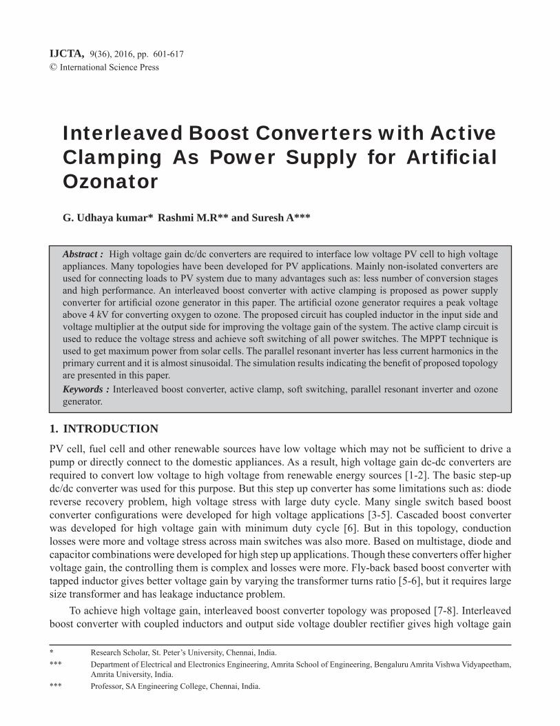
3. PROPOSED CONVERTER DESCRIPTION
The proposed active clamped interleaved boost converter is shown in Figure 2. This converter consists of dual coupled inductor with active clamp circuit and voltage multiplier cell. The active clamp circuit is used to reduce the voltage stress and achieve soft switching of main switches. The voltage gain is enhanced due to coupled inductor and voltage multiplier cell. The operation of converter is divided into eight modes which are described below.
Figure 2: Active Clamped Interleaved Boost Converter
Mode 1
During this mode switch S2 is turned on and the switch S1 remains in ON state. Inductors Lm1 and Lm2 store energy during this mode. The current fl ow is shown in Figure 3.(a). The capacitor C1 and C2 supply load during this mode.
Mode 2
During this mode S1 is turned off and S2 is still ON condition. The inductors get charged continuously. The output capacitor C1 and C2 supply the load as shown in Figure 3.(b)
Mode 3
During this mode as shown in Figure 3.(c), inductor Lm1 discharges the energy to the load and also charge the capacitor C1 through D1and S2. Capacitor C4 voltage is recycled though clamp switch Sc1.
604 G. Udhaya kumar, Rashmi M.R and Suresh A
Figure 3: (a) Mode-1 Operation
Figure 3: (b) Mode 2 Operation
605Interleaved Boost Converters with Active Clamping As Power Supply for Artifi cial Ozonator
Figure 3: (c) Mode 3 Operation
Figure 3: (d) Mode 4 Operation
606 G. Udhaya kumar, Rashmi M.R and Suresh A
Mode 4During this mode, the D1 turns off. The Lm1 deliver the energy directly to the load through coupled inductor and D3 as shown in Figure 3.(d). Inductor Lm2 starts storing energy through the switch S2.
Mode 5
During this mode both the switches S1 and S2 are ON as shown in Figure 3.(e). The current through diode Dr is controlled by the leakage inductances Lk2 and Lk1. Therefore the diode reverse recovery problem is resolved. During this mode, inductor Lm1 starts charging again. This mode ends when the current through the diode Dr ceases to fl ow.
Mode 6
During this mode, Diode D2 is reversed biased. Energy due to leakage inductance Lk2 will charge the capacitor C2. Hence the diode D2 is not affected subjected to reverse recovery problem. This mode is shown in Figure 3.(f). Magnetizing inductance Lm2 still transfers energy to the secondary side charging the capacitor Cr via diode Dr. The S1 current sum of currents of magnetizing inductances Lm1 and Lm2.
Figure 3: (e) Mode 5 Operation
607Interleaved Boost Converters with Active Clamping As Power Supply for Artifi cial Ozonator
Figure 3: (f) Mode 6 Operation
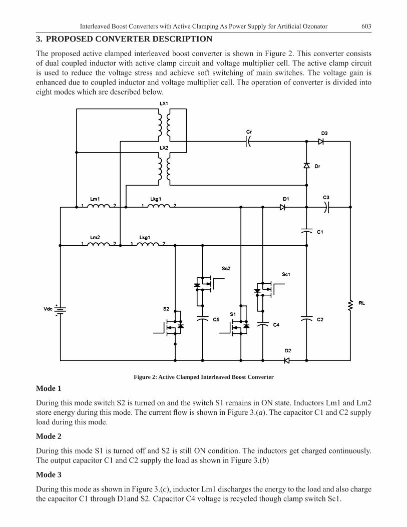
Mode 7
During this mode switch S2 is in off condition. Switch S1 and clamp switch Sc2 are ON. Inductor Lm2 discharges to the load. Capacitors C2 and C3 starts charging in this mode as indicates in Figure 3.(g). Capacitor C5 voltage is recycled though Clamp switch Sc2.
Mode 8
Diode D2 is reverse biased in this mode because of the leakage inductance Lk1 emf.. Magnetizing inductance Lm1 transfers the energy to the secondary side through coupled inductor and diode D3 as shown in Figure 3.(h).
Design Calculation
The converter output voltage is given by
V0 = in0
2(N 1) * V(1 – D )
(1)
608 G. Udhaya kumar, Rashmi M.R and Suresh A
Figure 3: (g) Mode 7 Operation
Figure 3: (h) Mode 8 Operation
609Interleaved Boost Converters with Active Clamping As Power Supply for Artifi cial Ozonator
Where N – Coupled inductor turns ratio = 1.2 D0 – Duty cycle = 0.55 Vin – Input voltage = 25 VSubsuite all input parameters into equation–1
V0 = 2(1.2 1) * 25(1 – 0.55)
V0 = 244V
The output current is given by I0 = 0VR
Where R = 133.3 I0 = 1.83AThe output power is given by Po = V0 * I0
Cr = 100fThe magnetizing inductance value is given by
Lm1 = Lm2 = Lm = 0
*(4 * I )
s
l
vdc tl
(5)
Lm = 120uH
5. SIMULATION RESULTS
The interleaved boost converter without active clamping and parallel resonant inverter is shown in Figure 4. This setup is used to provide supply to electrodes of ozonator. This circuit consist PV cells, interleaved boost converter, parallel resonant inverter, step-up transformer and electrode load. The MPPT technique is used to get maximum power from PV cells. The interleaved concept is used for getting high voltage gain and less output ripple. The parallel resonant inverter is used for converting DC to high frequency AC with less current harmonics. The step-up transformer is used to step-up primary voltage 300 V AC to 5 kV.
610 G. Udhaya kumar, Rashmi M.R and Suresh A
Figure 5 and 6 shows the gating pulse, current through and voltage across switch S1 and S2 of the interleaved boost converter respectively. Figure 7 shows the output voltage of interleaved boost converter. Figure 8 and 9 shows the gate pulse, current through and voltage across inverter switches S3, S6 and S4, S5 respectively. Figure 10 shows the output voltage and current.
Figure 4: Interleaved Boost Converter - Parallel Resonant Inverter Power Supply for Ozonator
Figure 5: Gate Pulse, Current and Voltage of Switch S1
611Interleaved Boost Converters with Active Clamping As Power Supply for Artifi cial Ozonator
Figure 6: Gate Pulse, Current and Voltage of Switch S2
Figure 7: Interleaved Boost Converter Output Voltage
Figure 8: Gate Pulse, Current and Voltage of Switch S3 & S6
612 G. Udhaya kumar, Rashmi M.R and Suresh A
Figure 9: Gate Pulse, Current and Voltage of Switch S4 & S5
As observed from Figures 5 and 6, the switch voltages and currents of boost converters are distorted which can be overcome by using clamping devices across the switches of interleaved boost converter.
Figure 10: Output Voltage and Load Current
The interleaved boost converter with active clamp fed parallel resonant inverter based power supply for Ozone generator system is as shown in Figure 11. The active clamp circuit is used to reduce the switch voltage stress and achieve soft switching of boost converter switches. The parallel resonant inverter is used for converting DC to high frequency AC with less current harmonics. The step-up transformer is used to step-up primary voltage 300 V to 5 kV.
613Interleaved Boost Converters with Active Clamping As Power Supply for Artifi cial Ozonator
Figure 11: Interleaved boost converter with active clamp circuit and parallel resonant inverter for ozonator
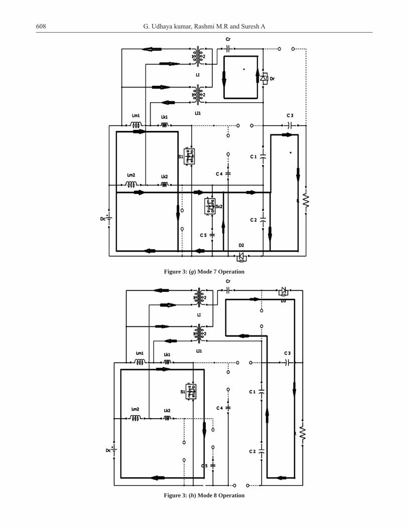
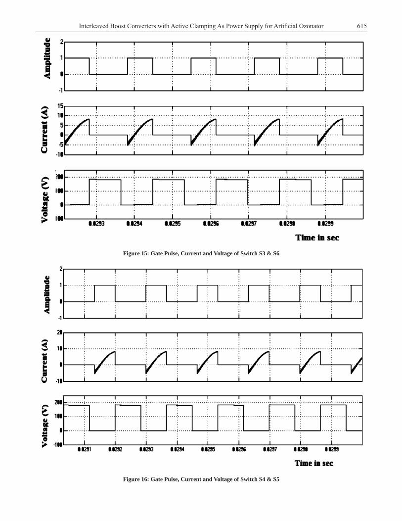
Figure 12 and 13 shows the gate pulse, current through and voltage of switch S1 and S2 of the interleaved boost converter. The switch voltage and currents have less distortion compared to the previous confi guration. Figure 14 shows the output voltage of interleaved boost converter. Figure 15 and 16 shows the gate pulse, current through and voltage across inverter switches S3, S6 and S4, S5 respectively. Figure 17 shows the output voltage and current.
Figure 12: Gate Pulse, Current and Voltage of Switch S1
614 G. Udhaya kumar, Rashmi M.R and Suresh A
Figure 13: Gate Pulse, Current and Voltage of Switch S2
Figure 14: Interleaved Boost Converter Output Voltage
The comparative analysis for interleaved boost converter with and without active clamping is given in Table-1
Table 1Comparative analysis
Parameters Without Active clamping circuit With Active clamping circuit
Input voltage (V) 25 25
DC link voltage (V) 246 271
Output power (W) 384 468.7
Effi ciency (%) 84.21 86
Output voltage peak amplitude 5640 6237
615Interleaved Boost Converters with Active Clamping As Power Supply for Artifi cial Ozonator
Figure 15: Gate Pulse, Current and Voltage of Switch S3 & S6
Figure 16: Gate Pulse, Current and Voltage of Switch S4 & S5
616 G. Udhaya kumar, Rashmi M.R and Suresh A
Figure 17: Output Voltage and Load Current
6. CONCLUSION
An actively clamped interleaved boost converter with parallel resonant inverter was proposed, designed and simulated. This circuit The proposed circuit and conventional circuit are simulated. Thus the proposed power supply for ozone generator system gives better performance in terms of less voltage stress, high voltage gain and high effi ciency 86%.
7. REFERENCES 1. F. Crescimbini, A. Lidozzi, G. L. Calzo, and L. Solero, “High-speed electric drive for exhaust gas energy recovery
applications,” IEEE Transactions on Industrial Electronics, vol. 61, no. 6, pp. 2998–3011, Jun. 2014.
2. Q. Zhao and F. C. Lee, “High-effi ciency, high step-up DC–DC converters,” IEEE Transactions on Power Electron-ics., vol. 18, no. 1, pp. 65–73, Jan. 2003.
3. G. Spiazzi, P. Mattavelli, and A. Costabeber, “High step-up ratio fl y back converter with active clamp and voltage multiplier,” IEEE Transactions on Power Electronics., vol. 26, no. 11, pp. 3205–3214, Nov. 2011.
4. F. Zhang, L. Du, F. Z. Peng, and Z. Qian, “A new design method for high-power high-effi ciency switched-capacitor DC–DC converters,” IEEE Transactions on Power Electronics., vol. 23, no. 2, pp. 832–840, Mar. 2008.
5. Y.-P. Hsieh, J.-F. Chen, T.-J. Liang, and L.-S. Yang, “Novel high step-up DC–DC converter with coupled-inductor and switched-capacitor techniques,” IEEE Transactions on Industrial Electronics., vol. 59, no. 2, pp. 998–1007, Feb. 2012
6. M. Muhammad, M. Armstrong, and M. Elgendy, “Non-isolated DC– DC converter for high step-up ratio applica-tions,” in Proc. 17th Eur. Conf. Power Electron. Appl. (EPE ECCE-Europe), Geneva, Switzerland, Sep. 2015, pp. 1–10.
7. W. Li, Y. Zhao, J. Wu, and X. He, “Interleaved high step-up converter with winding-cross-coupled inductors and voltage multiplier cells,” IEEE Transactions on Power Electronics., vol. 27, no. 1, pp. 133–143, Jan. 2012.
8. P. Vinoth Kumar, Dr.Suresh A. and Dr. Rashmi M.R. “Optimum Design of Single Stage Interleaved DC-DC Convert-er with Reduced Inductor Volume”, Australian Journal of Basic and Applied Sciences,Vol. 9, issue 1, pp. 258-264, January 2015.
617Interleaved Boost Converters with Active Clamping As Power Supply for Artifi cial Ozonator
9. Y. Zhao, W. Li, Y. Deng, and X. He, “Analysis, design, and experimentation of an isolated ZVT boost converter with coupled inductors,” IEEE Transactions on Power Electronics., vol. 26, no. 2, pp. 541–550, Feb. 2011.
10. Automatic detection of lung cancer nodules by employing intelligent fuzzy cmeans and support vector machine “,Biomedical Research
11. Marcos Alonso J, Jorge García,” Analysis, Design, “Experimentation of a High-Voltage Power Supply for Ozone Generation Based on Current- Fed Parallel-Resonant Push–Pull Inverter.” IEEE transactions on industry applica-tions, 2005; 41:no. 5.
12. Amjad, M. ; Univ. Teknol. Malaysia, Skudai, Malaysia ; Salam, Z. ; Facta, M. ; Mekhilef, S. “Analysis and Imple-mentation of Transformer less LCL Resonant Power Supply for Ozone Generation”, Power Electronics, IEEE Trans-actions , 2013 ;Volume:28 ; Issue: 2 : pp. 650 – 660.
13. G. Udhayakumar, Rashmi M R, K. Patel, G.P . Ramesh and Suresh A., (June 2015) “Supply Power Factor Improve-ment in Ozone Generator System Using Active Power Factor Correction Converter”, International Journal of Power Electronics and Drive Systems, Vol. 6, No. 2, , pp. 326-336
14. Udhayakumar, Rashmi M R, K. Patel and Suresh A.,(Feb 2016) “ High effi ciency Power Supply for Ozone Gener-ator with Input Power Factor Correction”, Springer series on Advances in Intelligent Systems and Computing , Vol. 394, pp.1215-1226