This is a repository copy of Internal corrosion of carbon steel pipelines for dense phase CO transport in Carbon Capture and Storage (CCS) - A review₂ .
White Rose Research Online URL for this paper:http://eprints.whiterose.ac.uk/99011/
Version: Accepted Version
Article:
Barker, R orcid.org/0000-0002-5106-6929, Hua, Y and Neville, A orcid.org/0000-0002-6479-1871 (2016) Internal corrosion of carbon steel pipelines for dense phase CO transport in Carbon Capture and Storage (CCS) - A review. International₂
Materials Reviews, 62 (1). pp. 1-31. ISSN 0950-6608
Items deposited in White Rose Research Online are protected by copyright, with all rights reserved unless indicated otherwise. They may be downloaded and/or printed for private study, or other acts as permitted by national copyright laws. The publisher or other rights holders may allow further reproduction and re-use of the full text version. This is indicated by the licence information on the White Rose Research Online record for the item.
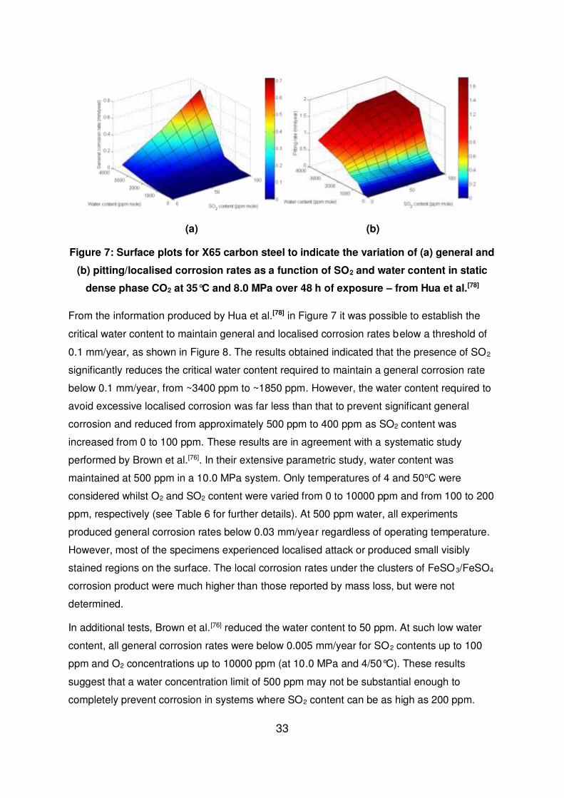
Takedown
If you consider content in White Rose Research Online to be in breach of UK law, please notify us by emailing [email protected] including the URL of the record and the reason for the withdrawal request.
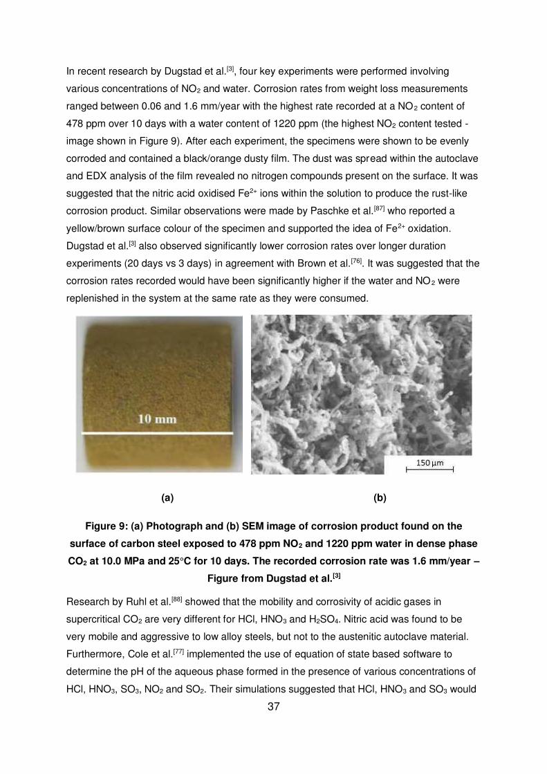
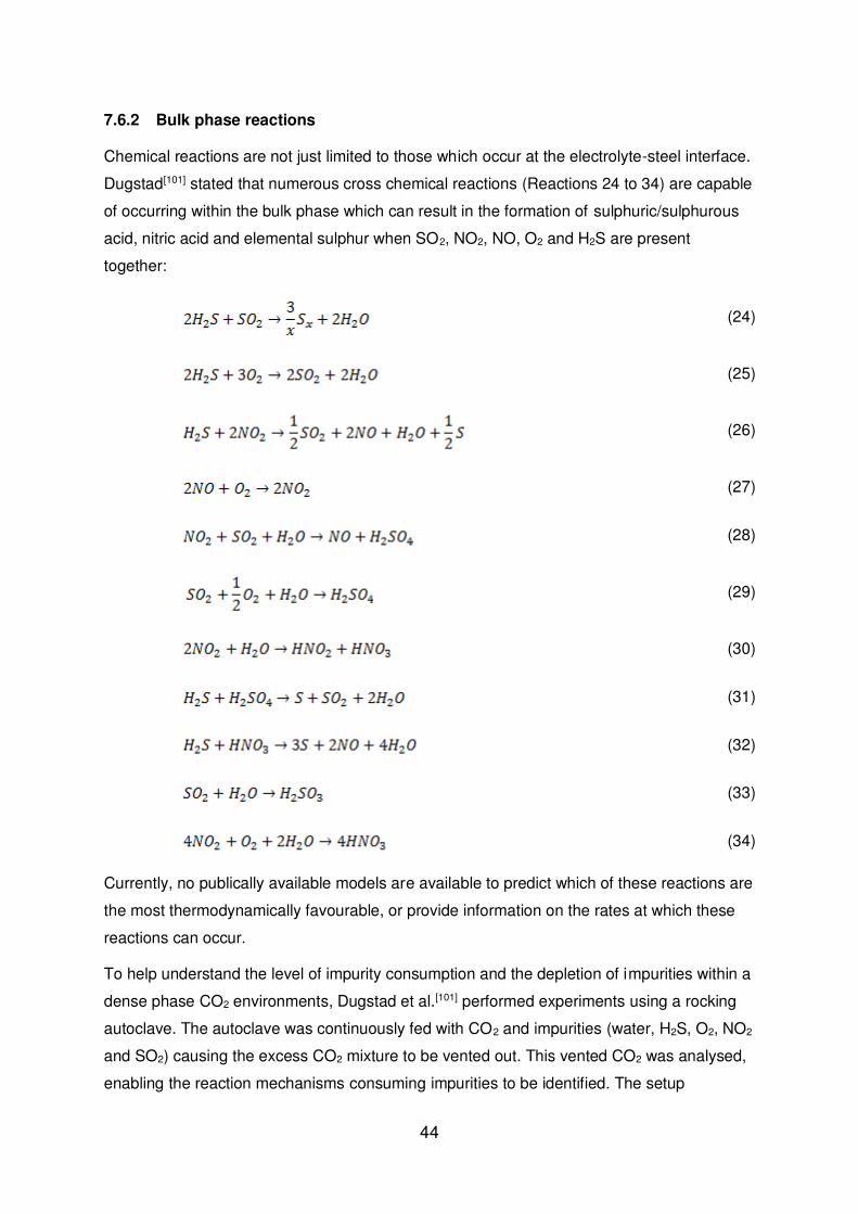
The initial research conducted by Dugstad et al[101] provides an interesting insight into the
numerous reactions capable within complex mixtures of impure dense phase CO2. This is
even without considering any of the reaction processes which occur on the steel surface.
The implementation of such a technique and an understanding of the likely reactions and
their kinetics is pivotal to be able to determine the change in CO2 stream chemistry along the
length of pipelines and whether this increases or decreases the risk of corrosion.
7.7 Depressurisation, accumulation of impurities and fracture
When dense phase CO2 is depressurised within a pipeline below the critical temperature, a
two-phase gas/liquid system will form. Within this system, compounds will partition between
the two phases and the concentration of impurities such as water, SO2 and NO2 will become
more concentrated in the remaining liquid phase.[26] When the water solubility in a particular
phase in exceeded, a third phase can also form. The accumulation of such impurities can
increase the corrosivity of the liquid phase significantly.[102]
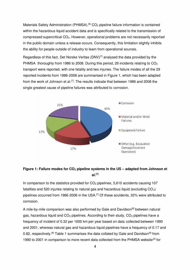
Very few experiments within the literature, other than the work of Dugstad et al.[102], focus on
the level of corrosion potentially encountered as a result of depressurisaton and
accumulation of impurities. Their research involved depressurisation experiments at 4 and
25°C in which autoclaves were vented via the gas phase. In order to ensure the corrosive
phase reached the carbon steel test material, thin carbon steel foils were placed in the
bottom of the autoclave to contact the sinking corrosive phase during depressurisation.
Dugstad and colleagues[102] found that when the system contained CO2 and water only (488
and 1222 ppm), the corrosion rate recorded was below 0.1 mm/year. The introduction of 138
ppm SO2 increased corrosion rates to just over 0.1 mm/year and covered the samples in a
black deposit. Perhaps most interesting was that the experiment in the presence of 191 ppm
NO2 produced corrosion rates reaching 0.9 mm/year. It is important to note that these tests
were closed system experiments and that the corrosion rate of the sample will have
inevitably reduced over time as the impurities were consumed on the steel surface.
Consequently, it could be argued that the value of 0.9 mm/year in the presence of NO2 may
have been substantially lower that the true corrosion rate for such a scenario.
In addition to the partitioning of phases, the expansion of CO2 from a region of high pressure
to a region of low pressure causes a decrease in system pressure due to the Joule-Thomson
effect. A sudden accidental release from a CO2 pipeline would cause rapid cooling and
potential embrittlement of the steel structure.[103] This process can lead to fracture of the
48
steel and the resulting cracks can then propagate along the pipeline. The problem is
exacerbated further by the fact CO2 exists as a two-phase mixture over a range of velocities,
meaning that the pressure at the crack tip is maintained at a high level during
propagation.[103] It is necessary to ensure that any propagating cracks are arrested.
7.8 Solid product formation
Various authors have reported the formation of solid products (believed to be elemental
sulphur) in the bottom of autoclaves when performing experiments with complex mixtures of
impurities.[76, 101] The formation mechanism for elemental sulphur is currently uncertain,
although the formed acids within the system can potentially take part in the generation of
elemental sulphur as shown previously in Reactions (31) and (32) with the Claus process
(Reaction (24)) also becoming important. However, Brown et al.[76] also suggested that the
H2S-O2 reaction has the potential to form elemental sulphur at very low H2S and O2
concentrations i.e. in the ppb range:
(35)
Currently, no information relating to Reaction (35) in dense phase CO2 has been found.
However, Brown et al.[76] stated that conversion of 100 ppm H2S would produce in excess of
100 tons of sulphur per year for a 20’’ pipeline at a flow velocity of 1.5 m/s. Consequently,
understanding sulphur formation and its associated mechanisms is crucial to ensure efficient
and safe CO2 transport.
Furthermore, in terms of the build-up of solid compounds, the presence of corrosion
products on the pipe wall can also pose an issue and requires consideration. A 0.1 mm thick
FeCO3 corrosion product on a 100 km long 20’’ line would produce approximately 50 tons of
solids[76], whilst FeSO3/FeSO4 would produce approximately 58 to 66 tons for the same
thickness. A degree of understanding of the tenacity of the corrosion product to the inner
wall may be required to understand the risks associated with corrosion product formation
and build-up.
8 Stress corrosion cracking
Currently, corrosion research in CO2 transport has focused on identifying corrosion rates
during CO2 transport. The risk of Stress Corrosion Cracking (SCC) has not been extensively
investigated. A recent conference paper by Sandana et al. [104] explores the possibility of SCC
in CO2 transportation lines. The paper also highlights gaps in the current knowledge and
provides some preliminary test results that indicate that SCC may be of concern. A summary
49
of this review is provided here for completeness, but the reader is referred to the paper in
question for a detailed discussion of the risk of SCC in CO2 pipelines.
8.1 Effect of Carbon Monoxide
The presence of carbon monoxide (CO) is likely under pre-combustion processes. Sandana
et al.[104] stated that cracking of carbon steels was observed in wet CO2-CO environments in
the 1970's. The interest generated in this area led to the first studies by Brown et al. [105] and
Kowaka and Nagata[106] into SCC in CO2-CO-H2O systems. The aforementioned research
indicated that the presence of water is critical for the incidence of cracking and that CO can
promote trans-granular cracking in carbon steels. Brown et al. [105] showed that an increase in
CO activity promoted faster crack growth and reduced the minimum initial stress required for
SCC to occur. Interestingly, the results also indicated that the introduction of O2 into the
system resulted in an increase in SCC susceptibility. Unfortunately, the majority of this data
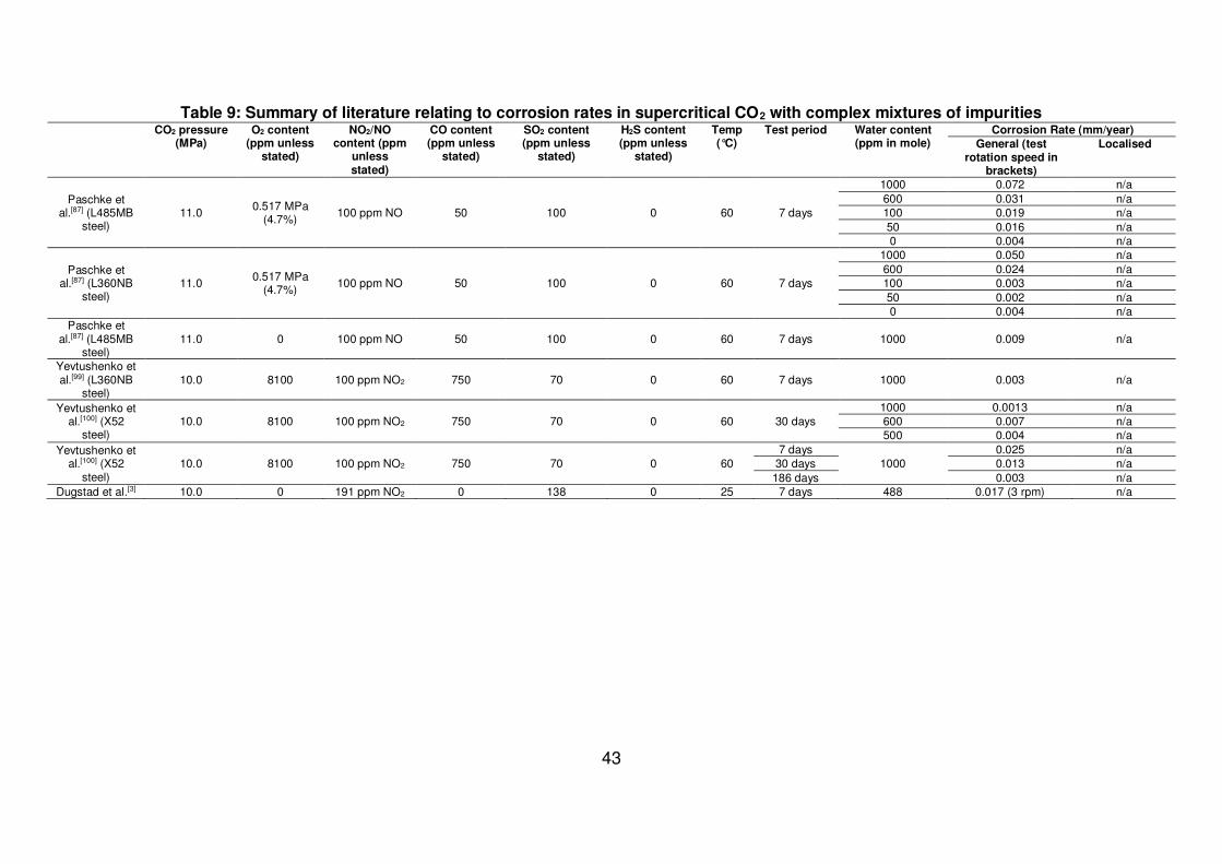
is limited to partial pressures of CO2 below 2.0 MPa, so the conditions are not particularly
reflective of those likely to be encountered during CO2 transport. Consequently, there is a
requirement to explore the likelihood of SCC occurring in high pressure CO2-CO-H2O
environments during upset conditions under which the dehydration process might fail,
resulting in significant water presence in the pipeline.
8.2 Effect of Hydrogen Sulphide
Even though supercritical CO2 lines have been in operation for approximately 40 years,
there are few standards which relate to their design or construction.[107] ASME B31.4 is the
standard which describes the design and construction requirements of supercritical CO2
pipelines, although there is no mention of H2S in the CO2 or any requirement to consider the
potential for cracking from H2S.[107]
H2S can be present as an impurity in both anthropogenic and natural sources of CO2 and
can result in both Sulphide Stress Corrosion Cracking (SSCC) and Hydrogen Induced
Cracking (HIC). Although these threats and their associated mitigation techniques have been
covered extensively by the oil and gas industry by ANSI/NACE MR0175/ISO 15156[108], CO2
pipelines are not specifically covered by these standards and the threat of SSCC and HIC
needs to be considered, particularly where the CO2 source contains H2S.[107]
8.3 Effect of bicarbonates, sulphates and nitrates
The risk of bicarbonate/carbonate internal SCC is unlikely given that there is no surface
electrochemical polarisation to drive internal pipeline surface steel potential into the SCC
critical range for initiation.[104] Furthermore, the intergranular SCC of low alloyed steels in
50
bicarbonate/carbonate systems is usually referred to as high-pH SCC since it readily occurs
in solution of pH 9-10.[104] The typically low pH encountered in the aqueous phase is
expected to reduce the likelihood of SCC. It is also expected that relatively low
concentrations of bicarbonates would be present in the aqueous phase, also minimising the
risk of SCC.
In terms of SOx and NOx, it is important to consider the potential effects these impurities may
have on the SCC mechanisms in CO2 pipelines. The presence of nitrates, sulphates and
even sulphide films may have the ability to promote SCC.
Nitrates are known to cause SCC of carbon steel on their own, with the susceptibility to
cracking increasing with the concentration of nitrates and temperature. [104] The occurrence of
SCC becomes significant at temperatures above 70°C due to the rapid formation of an
Fe3O4 film[104]. Whether this process is capable of occurring at lower temperatures is
unknown, but the risk is thought to be low.[104]
8.4 Quantifying the risk of SCC and HIC in supercritical CO2 pipelines
From an extensive review of the literature, it appears that there are no studies relating to
SCC or HIC of pipeline steels when exposed to supercritical CO2 containing H2S.
Clarification is required as to whether SCC or HIC can even occur under these conditions
and whether the threshold conditions established for H2S to avoid cracking in oil and gas
service would be applicable to supercritical CO2 pipelines.[107]
The risk of HIC and SCC are dependent upon the presence of an aqueous phase within the
pipeline. In the presence of such a phase, SCC is obviously a potential risk. When H2S and
other impurities are present in the CO2 stream, the rapid and catastrophic nature of SCC
makes its consideration essential. In contrast, HIC is generally a much slower cracking
mechanisms, but still requires attention.
Although there are currently no regulatory requirements to design and construct dense
phase CO2 pipelines to resist SCC and HIC, it is essential to mitigate their risk of
occurrence. Furthermore, because these processes are reliant upon the presence of a
significant aqueous phase (which would only effectively be present during upset conditions
i.e. failure of the dehydration system) it is perhaps prudent to determine the requirement for
SCC and HIC resistance based on the frequency and duration of upset conditions as well as
how these materials behave during long term exposure to an aqueous phase.[104]
Until SCC and HIC tests are performed in supercritical CO2 in the presence of impurities
such as NOx, SOx and H2S, it is impossible to be confident that SCC and/or HIC are not
potential risks for dense phase CO2 pipelines.
51
As a final note, the expected low pH (~pH of 3 without impurities in CO2 stream) of the
aqueous phase within the pipeline has the potential to cause significant hydrogen adsorption
and permeation. Although CO2 is less aggressive than H2S in enhancing the adsorption of
hydrogen in steels, it still contributes to the adsorption process.[107] There is also the
possibility for hydrogen to accumulate within traps and remain after water has been
removed. Therefore, periodic upsets could result in significant accumulation of hydrogen,
leading to HIC at a later stage.[107]
9 Issues associated with closed system laboratory
experiments, replicating field conditions and
defining a safe operating window
Currently, no reliable prediction models are available for anthropogenic dense phase CO2
transport.[103] Although numerous corrosion prediction models for CO2 corrosion in oil and
gas environments exist, extending the models to pressures and conditions typical of CCS
could pose challenging. The models would be unable to account for the additional
anthropogenic impurities expected from flue gases such as NOx and SO2.
One model has recently been proposed within the literature for supercritical CO2-SO2-O2-
H2O environments.[109] The details of the model by Xiang et al.[109] are beyond the scope of
this review, however it was established using a combination of standard CO2 models and an
atmospheric corrosion model and is yet to be correlated or verified by field data.
In order to develop a reliable and uniformly acceptable corrosion model, researcher and
stakeholders must develop a standardised methodology for the evaluation of materials in
dense phase CO2 transport environments. Currently, no standards exist in relation to
performing laboratory experiments to replicate the conditions encountered in the field. The
absence of a standard methodology for performing laboratory corrosion experiments has
produced results which may be of limited use in terms of selecting materials or identifying
safe conditions for CO2 transport.[103] There are a number of issues and/or limitations
associated with performing laboratory experiments which represent field conditions and the
following main aspects are discussed within this section:
replicating dynamic conditions
addition of impurities prior to pressurisation
consumption of impurities during testing
application of electrochemical techniques in dense phase CO2
52
9.1 Replicating dynamic conditions
It has been suggested in literature that the presence of flow within the system is capable of
reducing the extent of water condensing onto the steel surface and subsequently minimising
the level of corrosion.[81, 83]
In terms of supporting the theory, the work of Farelas et al. [83] demonstrated that the
presence of flow (1000 rpm sample rotation speed) reduced corrosion rates of X65 steel by
around an order of magnitude in specific dense phase CO2 environments. Farelas et al.[83]
performed tests at 8.0 MPa in both liquid (25°C) and supercritical (50°C) conditions with the
addition of 650 ppm water and 0.008 MPa (0.1 %) SO2. General corrosion rates reduced as
a result of the transition from static to dynamic from 0.03 to 0.02 mm/year in supercritical
conditions and from 0.1 to 0.01 mm/year in liquid CO2.
9.2 Addition of impurities prior to pressurisation
Numerous studies have been conducted in autoclaves where water is introduced into the
autoclave followed by SOx, NOx, H2S etc. before pressurisation.[3, 23, 70-72, 78, 81, 110] It is
theoretically possible for the water to initially react with SOx and NOx to produce sulphuric
and nitric acid before the system is pressurised. It could be argued that such an approach
does not produce an accurate representation of CO2 transport conditions.
9.3 Consumption of impurities
Perhaps the main issue associated with closed loop/system testing is the depletion of
impurities within the system over the course of the experiment. The rate of consumption of
impurities is dependent upon the corrosion rate of the sample, the steel surface area to fluid
volume ratio and the bulk/surface corrosion mechanisms.[76] The actual level of consumption
by corrosion in NO2/SO2 experiments was measured by the Institute for Energy (IFE).[76]
They found that the level of impurity consumption was much greater than that expected from
solely the corrosion rate of the sample. A large part of the impurities were reported to
become ‘non-active’ in the system. This was believed to be a combination of immobilisation
of the corrosive phase and reactions in the bulk fluid.[76]
With only a small part of the impurity consumption being attributed to corrosion, it could be
questioned whether the corrosion rates recorded in such systems reflect a worst case
scenario. These results support the requirement for a dynamic tests system whereby the
impurity levels are continuously monitored and dosed precisely to maintain a constant
stream composition.
53
9.4 Application of electrochemical techniques in dense phase CO2
Real-time in-situ measurements of corrosion rates of materials exposed in impure dense
phase CO2 would enable instantaneous measurements of corrosion rates which can be
linked to the formation of protective corrosion products, increased sensitivity for low
corrosion rates and potentially an understanding for how depletion in impurities related to the
observed decline in steel corrosion rate.[111] The issue associated with performing
electrochemical measurements in dense phase CO2 are its low conductivity, even when
saturated with water vapour.
Previous attempts to perform electrochemical measurements in dense phase CO2 where
conducted by Thodla et al.[23] and Ayello et al..[110] A flush mounted probe was used with the
electrodes mounted in an electrically insulated material with the cross-section exposed as
the active surface. When the probe was polished, a flat surface was presented for
condensation to occur on. A probe of this design, however, requires a certain degree of
surface wetting, to enable conductivity between all electrodes (in this case, a three-electrode
cell was implemented). Such a process can be intermittent and unreliable during long term
testing. To overcome this issue, Thodla et al. [23] and Ayello et al.[110] administered water
droplets to the steel surface in-situ at high pressure to maintain conductivity. However, such
a thick water film may not be wholly representative of the films encountered in a CO2
pipeline.
Recently, however, Beck et al.[111] produced a novel design involving the use of a three
electrode flush mounted probe coated with an ion conducting polymer. Wetting of the
polymer by moisture in the dense phase CO2 enables sufficient electrolyte conductivity to
perform electrochemical measurements without administering water directly onto the steel
surface.
10 Material selection for CO2 transport
Information pertaining to the assessment of the corrosion behaviour of corrosion resistant
alloys (CRAs) in conditions similar to those encountered in CO2 transport (i.e. dense phase
CO2) is relatively sparse in the literature. It is the opinion of some authors that the use of
CRAs (stainless steels) may be capable of mitigating the corrosion risk during dense phase
CO2 transport.[112, 113] Although this is most likely impractical from an economic perspective
for long distance pipelines, caution still needs to be exercised if these materials are
considered as the pH of the aqueous phase could potentially become low enough to
dissolve the passive film on some of these materials, causing extensive pitting corrosion or
localised attack. This statement is supported by the work of Yevtushenko et al.[99, 100] who
evaluated the performance of X20Cr13 and X46Cr13 in a circulating impure dense phase
54
CO2 system. Corrosion experiments performed at 10.0 MPa and 60°C in the presence of
1000 ppm water, 70 ppm SO2, 100 ppm NOx, 750 ppm CO and 8100 ppm O2 produced
severe pitting corrosion of X20Cr13 and slight pitting of X46Cr13.
Choi et al.[4] also reviewed the corrosion behaviour of X65 steel in comparison to 13Cr in
water-saturated CO2 in 24 hour experiments at 8.0 MPa CO2 and 50°C in the presence of
1% SO2 and 4% O2. They recorded a corrosion rate of 7 mm/year for both X65 and 13Cr,
indicating that the CRA produced no beneficial effect in the form of corrosion mitigation.
To reinforce these observations, experiments performed by Dugstad et al.[101] at 10.0 MPa
and 25°C in the presence of 300 ppm water, 100 ppm NO2, 100 ppm SO2, 350 ppm O2 and
100 ppm H2S for 147 hours produced signs of corrosion attack on the Hastelloy autoclave
used for the corrosion experiment, indicating the level of corrosivity of the aqueous phase
which can be produced in such systems.
In light of the previous paragraphs, it must be noted that the effectiveness of CRAs will be
heavily dependent upon the level and type of contaminants within the system and how they
influence the pH of the aqueous phase formed on the pipe wall. For example, if ‘appreciable’
levels of nitric acid were to be present in the aqueous phase, it is unlikely that CRAs will offer
any significant benefit in terms of mitigating corrosion as the protective passive film will not
be stable under the conditions in the aqueous phase due to the low pH. However, if the
impurity is H2S or O2, or a purely CO2-H2O system is considered with a high water content,
then CRAs may be able to mitigate the effects of corrosion. The question then becomes
whether the construction of pipelines using CRAs is economically feasible, and this is
unlikely to be the case.
In summary, it is possible that CRAs and low Cr-bearing steels could offer superior corrosion
protection compared to carbon steels for pipeline or downhole tubing materials whilst still
remaining an economic alternative. However, this will be heavily dependent upon the type
and level of impurities in the system and the conditions of the aqueous phase. The results of
Yevtushenko et al.[99, 100], Choi et al.[4] and Dugstad et al.[101] all demonstrate that
considerable corrosion can take place even on CRAs if specific impurities are present at
high enough concentrations (namely SO2 and NO2). However, in contrast, other research by
Choi et al.[97] has suggested that under the correct environmental conditions (CO2-H2O-H2S),
even 1Cr and 3Cr bearing steel are capable of reducing corrosion rates to acceptable levels
when carbon steel is unable to perform, enabling a wider tolerance on impurity contents. The
decision to move to a more ‘corrosion resistant’ material is one that should not be taken
lightly and should be supported by experimental work under appropriate conditions to
determine the level of effectiveness.
55
11 Corrosion inhibition in CO2 transport
11.1 Potential of neutralising amines
It is evident that sufficient drying of the dense phase CO2 is capable of preventing the
breakout of free water and excessive corrosion rates. However, this contributes towards an
increase in handling costs, particularly for offshore installations. Although the application of
CRAs such as 13Cr are an option, they are expensive and appear to have little corrosion
resistance to SO2/NO2 environments.[103] Therefore, the use of corrosion inhibitors may be
the most appropriate corrosion mitigation technique for such instances.
Neutralising amines, in particular, offer themselves as a potential option to help prevent the
corrosion caused by strong acids in systems where water condenses onto a metallic surface.
Regrettably, the selection of an appropriate neutralising amine usually involves making
compromising choices amongst their properties. For example, each amine possesses
unique properties which dictate their ability to evaporate, to form liquid/solid salts, along with
how quickly/readily they partition into the first drops of water, which condense onto a steel
surface.[114] There is no one amine which exhibits all the desirable properties required,
meaning that the compounds need to be carefully selected to perform the best form of
corrosion inhibition. A number of properties require consideration when selecting an
appropriate amine corrosion inhibitor. These include boiling point, the effect of excess
amine, the vapour-liquid equilibrium, the base strength and potential salt formation.
A review of corrosion inhibitors would not be appropriate in this article given that no one
inhibitor is universally applicable and usually a cocktail of chemicals are administered to
control degradation of metals. Furthermore, although corrosion inhibitors have been
reviewed extensively for oil and gas environments, there is a significant difference between
the operating conditions, the dominant phase and the level and type of contaminants
compared to CO2 transport. Limited research exists in which inhibitors have been reviewed
in dense-phase CO2 with low water contents and this difference in operating conditions and
environment may render an inhibitor ineffective for such an application, even if it performs
well in a system where the aqueous phase dominates. Exceptions include the work of
Turgoose[115] and a recent presentation by Dugstad at a National Association of Corrosion
Engineers Technology Exchange Group Session[116], although the inhibitor chemistries were
not disclosed in these publications.
Currently, little or no information exists on chemical inhibitors which have been evaluated in
environments containing flue gas impurities. If inhibitors are to be developed for CO2
transport upset conditions, it is imperative they are evaluated in conditions which reflect
56
those which they will be used in as accurately as possible to ensure they are compatible with
any anticipated impurities.
11.2 Environmental concerns in corrosion inhibition
One of the additional concerns with the application of corrosion inhibition for CO2 pipeline
materials is that any impurities or components added to the CO2 stream will be injected into
the chosen storage site if left untreated. Consequently, it is imperative that any unsuitable
components are removed from the stream prior to injection, or that the residual
concentration and environmental properties of the chemical are such that they do not
adversely affect the environment where they are injected.
As well as providing sufficient levels of chemical inhibition, any components chosen should
be non-toxic with high biodegradability and reduced bioaccumulation.[117] Whether a
chemical is environmentally acceptable or not is usually determined by the national
regulations of a particular country. In terms of the North Sea where numerous potential
sequestration sites exist, this location is well regarded as having stringent criteria regarding
chemical requirements compared with the rest of the world.
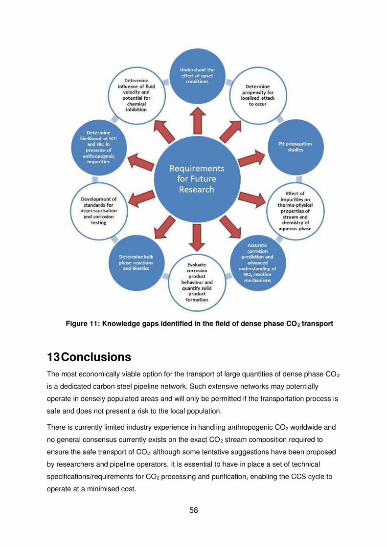
12 Knowledge gaps
Reflecting on the previous Chapters within this review, it is evident that knowledge gaps still
exist in the literature which if left unaddressed, will cast ambiguity over the long term safety
and efficiency of dense phase CO2 transport via carbon steel pipelines. Figure 11 highlights
the different areas where research attention should be directed based on this review. In the
opinion of the authors, there are four key areas from Figure 11 which require significant
attention. These are listed below and outlined in the following section:
i. Predicting the thermo-physical properties of the CO2 stream
ii. Understanding the mechanisms of localised corrosion
iii. Understanding upset conditions and elucidating NOx reaction mechanisms
iv. Determining bulk phase reactions and kinetics
It is important to stress that other areas exist in addition to the aforementioned, however, the
four listed here are regarded as priority areas.
12.1 Predicting the thermo-physical properties of the CO2 stream
One of the key requirements for safe transport is to understand the thermo-physical
properties of the process fluid being transported and how this is influenced by the presence
of impurities. In addition is important to understand how the impurities within the system
segregate into the aqueous phase, so that the chemistry can be accurately related to the
57
extent of degradation observed within the system. Accurately determining the role of
impurities in influencing the physical properties of the CO2 stream (density, viscosity), the
solubility of water in impure CO2 and the conditions in the aqueous phase is essential if the
corrosion processes are to be understood and if accurate prediction of corrosion rates is to
be made possible.
12.2 Understanding the mechanisms of localised corrosion
Understanding the relationship between the species present in the CO2 stream, the
corrosion products formed on the steel surface and how this is related to the ability of pits to
initiate and propagate is important to determine whether localised corrosion is a true threat
to pipeline integrity. Most importantly it is essential to establish a robust
methodology/standard for simulating dense phase CO2 transport in laboratory experiments
and to overcome the issues previously identified in this review (depletion of impurities and
change in bulk phase chemistry with time in particular).
12.3 Understanding upset conditions and elucidating NOx reaction mechanisms
One aspect which has resulted in failures in past CO2 lines was caused by free standing
water in the system. It is important to understand the effects of ‘upset’ conditions within the
system which can cause extremely high degradation rates. This will enable operators to
understand the potential risk and extent of damage cause in the event of water ingress into
the system. Furthermore, the limited number of experiments with NOx (even under normal
service conditions) have shown that this particular component has the ability to be
particularly aggressive, resulting in very fast corrosion kinetics. Further study of this
component and its potentially synergistic behaviour with other compounds in the CO2 stream
(particularly through the lead chamber effect) is required to understand the corrosion
processes and define the safe stream compositions for transport.
12.4 Determining bulk phase reactions and kinetics
Studies have indicated that in multi-impurity systems, the bulk phase composition can
change over time and consequently, along the length of a pipeline. A better understanding of
potential bulk phase reactions is required to determine whether the CO2 stream exhibits any
change in its corrosive nature along the length of a pipeline. This is an important area of
research as will impact the corrosion management strategy significantly in long distance
pipelines.
58
Figure 11: Knowledge gaps identified in the field of dense phase CO2 transport
13 Conclusions
The most economically viable option for the transport of large quantities of dense phase CO 2
is a dedicated carbon steel pipeline network. Such extensive networks may potentially
operate in densely populated areas and will only be permitted if the transportation process is
safe and does not present a risk to the local population.
There is currently limited industry experience in handling anthropogenic CO2 worldwide and
no general consensus currently exists on the exact CO2 stream composition required to
ensure the safe transport of CO2, although some tentative suggestions have been proposed
by researchers and pipeline operators. It is essential to have in place a set of technical
specifications/requirements for CO2 processing and purification, enabling the CCS cycle to
operate at a minimised cost.
59
Although tentative guidelines exist in the literature for the CO2 stream quality, experiments
have confirmed that reactions between impurities can occur at ppm level and that multi -
impurity systems with impurity concentrations less than the recommended concentrations
suggested by DYNAMIS, Alstom, IPCC etc. are corrosive towards carbon steel and result in
the formation of nitric/sulphuric acids which are able to lower the critical water content at
which general and localised corrosion is initially observed.
The distinct lack of corrosion data from both laboratory experiments and the field where
anthropogenic CO2 is transported makes accurate corrosion prediction challenging. This is
particularly true for impurities such as NOx and H2S, for which there is a lack of
understanding in the general/localised corrosion behaviour, mechanisms and corrosion
product formation in dense phase systems. Furthermore, chemical reactions are not just
limited to those which occur at the electrolyte-steel interface. Numerous reactions are
capable in the bulk phase between H2S, NO, NO2, SO2, O2 and water. To better understand
the corrosion rates in pipelines, there is a requirement to fully understand these reaction
processes, the formation of separate corrosive phases and how these influence material
degradation to define the safe operating window for CO2 transport.
The risk of SCC and HIC to occur is dependent upon the presence of an aqueous phase.
Although there are no regulatory requirements to construct dense phase CO2 pipelines to
resist SCC or HIC, it is essential to prevent such mechanisms from occurring. Until SCC and
HIC tests are performed in supercritical CO2 in the presence of impurities such as NOx, SOx
and H2S, it is impossible to be confident that SCC and/or HIC are not potential risks for
dense phase CO2 pipelines.
Various experimental challenges exist in replicating the conditions encountered during CO2
transport, particularly for closed system tests with ppm-range concentrations. These include
depletion of impurities through reactions with the steel surface, but also reactions in the bulk
fluid resulting in the formation of acid phases, or solid products such as elemental sulphur.
Furthermore, no standards exist for corrosion experiments in dense phase impure CO2. An
ideal laboratory experiment would involve a dynamic tests system whereby the impurity
levels are continuously monitored and dosed/vented precisely to maintain a constant stream
composition.
Based on the literature relating to material selection, alternate materials other than carbon
steels (such as corrosion resistant alloys) for long-distance dense phase CO2 pipelines are
unlikely given their associated costs. Furthermore, research suggests that the corrosivity of
the aqueous phase is too severe even for these materials when impurities such as SO2 and
NO2 are present in appreciable concentrations.
60
The application of corrosion inhibitors through continuous injection is an alternative option to
CRAs for long distance dense phase CO2 pipelines. It is also possible that inhibitors could
be applied exclusively in the event of ‘upset’ conditions (i.e. failure of dehydration system) to
mitigate significant levels of corrosion. However, in such instances the environmental
properties of the chemical used needs to be carefully considered if there is no intention to
remove the inhibitor prior to injection.
14 Acknowledgements Dr Barker would like to express his thanks to the National Association of Corrosion
Engineers (NACE) and their technical committee for their financial support which provided
him with the opportunity to contribute towards the research field of corrosion in CO2
transportation pipelines and also enabled him to write this review article.
15 References
1. M.E. Boot-Handford, J.C. Abanades, E.J. Anthony, M.J. Blunt, S. Brandani, N. Mac Dowell, J.R. Fernandez, M.-C. Ferrari, R. Gross, J.P. Hallett, R.S. Haszeldine, P. Heptonstall, A. Lyngfelt, Z. Makuch, E. Mangano, R.T.J. Porter, M. Pourkashanian, G.T. Rochelle, N. Shah, J.G. Yao, and P.S. Fennell, "Carbon capture and storage update", Energy & Environmental Science, 7, 1 (2014): p. 130-189.
2. OECD Publishing and International Energy Agency, Energy Technology Perspectives 2010: Scenarios and Strategies to 2050. (2010): Organisation for Economic Co-operation and Development.
3. A. Dugstad, M. Halseid, and B. Morland, "Effect of SO2 and NO2 on corrosion and solid formation in dense phase CO2 pipelines", Energy Procedia, 37, (2013): p. 2877-2887.
4. Y.-S. Choi, S. Nešić, and D. Young, "Effect of impurities on the corrosion behavior of CO2 transmission pipeline steel in supercritical CO2−water environments", Environmental Science & Technology, 44, 23 (2010): p. 9233-9238.
5. J. Watt, "Carbon dioxide transport infrastructure - key learning and critical issues", Journal of Pipeline Engineering, 9, (2010): p. 213-222.
6. Office of Pipeline Safety (OPS) within the U.S. Department of Transportation, Pipeline and Hazardous Materials Safety Administration, ''Pipeline Incident 20 Year Trends", [Online], Available at: http://www.phmsa.dot.gov/pipeline/library/datastatistics/pipelineincidenttrends, Accessed on: 11th March 2015.
7. K. Johnson, H. Holt, K. Helle, and O.K. Sollie, "Mapping of potential HSE issues related to large-scale capture, transport and storage of CO2 (Det Norsk Veritas, Horvik. Norway)", (2008).
8. J. Gale and J. Davison, "Transmission of CO2 - safety and economic considerations", Energy, 29, 9–10 (2004): p. 1319-1328.
9. J.M. West. "Design and operation of a supercritical CO2 pipeline - Compression system SACROC unit, Scurry County, Texas", SPE Permian Basin Oil Recovery Conference, (Midland, Texas 1974).
10. F.W. Schremp and G.R. Roberson, "Effect of supercritical carbon dioxide (CO2) on construction materials", SPE, 15, 3 (1975): p. 227-233.
11. T.E. Gill. "Ten years of handling CO2 for SACROC unit", SPE Annual Technical Conference and Exhibition, (New Orleans, Louisiana 1982).
12. L.E. Newton, Jr. and R.A. McClay. "Corrosion and operational problems, CO2 project, SACROC unit", SPE Permian Basin Oil and Gas Recovery Conference, (Midland, Texas 1977).
13. A. Oosterkamp and J. Ramsen, "State-of-the-art overview of CO2 pipeline transport with relevance to offshore pipelines", Polytech Report No: POL-O-2007-138-A, (2008).
14. Kinder Morgan, "CO2 Transportation pipelines", [Online], Available at: http://www.kindermorgan.com/business/co2/transport.cfm. Accessed on 11th March 2015.
15. D.E. McCollough and R.L. Stiles. "Operation of the Central Basin CO2 pipeline system", SPE California Regional Meeting, (Ventura, California, 1987).
16. E. de Visser, C. Hendriks, M. Barrio, M.J. Mølnvik, G. de Koeijer, S. Liljemark, and Y. Le Gallo, "Dynamis CO2 quality recommendations", International Journal of Greenhouse Gas Control, 2, 4 (2008): p. 478-484.
17. T. Maldal and I. Tappel, "CO2 underground storage for Snøhvit gas field development", Energy, 29, 9 (2004): p. 1403-1411.
18. S. Walspurger and H.A.J.v. Dijk, "EDGAR CO2 purity: type and quantities of impurities related to CO2 point source and capture technology: a literature study", ECN-E-12-054, (2012).
19. A. Prelipceanu, H. Kaballo, and U. Kerestecioglu. "Linde rectisol wash process", 2nd International Freiberg Conference on IGCC & XtL Technologies, (Freiberg, Germany, 2007).
20. European Communities Report: Implementation of directive 2009/31/EC on the geological storage of carbon dioxide, ISBN-13 978-92-79-19834-2, (2011): p. 66.
21. A. Aspelund and K. Jordal, "Gas conditioning - The interface between CO2 capture and transport", International Journal of Greenhouse Gas Control, 1, 3 (2007): p. 343-354.
22. G. Pipitone and O. Bolland, "Power generation with CO2 capture: Technology for CO2 purification", International Journal of Greenhouse Gas Control, 3, 5 (2009): p. 528-534.
23. R. Thodla, A. Francois, and N. Sridhar. "Materials performance in supercritical CO2 environments", CORROSION 2009, (Atlanta, GA: NACE, 2009).
24. K.R. Kanimozhi, S. Papavinasam, R. Shyamala, and J. Li. "Effect of monoethanolamine (MEA) on the corrosion rates of carbon steels and stainless steels in CO2 saturated NaCl solutions", CORROSION 2014, (San Antonio: TX: NACE).
25. A. Dugstad, S. Clausen, and B. Morland. "Transport of dense phase CO2 in C-steel pipelines - when is corrosion an issue?", CORROSION 2011, (Houston, TX:NACE, 2011).
26. M. Halseid, A. Dugstad, and B. Morland, "Corrosion and bulk phase reactions in CO2 transport pipelines with impurities: Review of recent published studies", Energy Procedia, 63, (2014): p. 2557-2569.
27. Y.-S. Choi and S. Nešić. "Effect of water content on the corrosion behavior of carbon steel in supercritical CO2 phase with impurities", CORROSION 2011, (Houston, TX:NACE, 2011).
28. I.S. Cole, P. Corrigan, S. Sim, and N. Birbilis, "Corrosion of pipelines used for CO2 transport in CCS: Is it a real problem?", International Journal of Greenhouse Gas Control, 5, 4 (2011): p. 749-756.
29. T. Lazic, E. Oko, and M. Wang, "Case study on CO2 transport pipeline network design for Humber region in the UK", Proceedings of the Institution of Mechanical Engineers, Part E: Journal of Process Mechanical Engineering, 228, 3 (2013): p. 210-225.
30. P.N. Seevam, J.M. Race, M.J. Downie, and P. Hopkins. "Transporting the next generation of CO2 for carbon, capture and storage: the impact of impurities on supercritical CO2 pipelines", 7th International Pipeline Conference, (Calgary, Alberta, Canada: American Society of Mechanical Engineers, 2008).
31. H. Li and J. Yan. "Impact of impurities in CO2-fluids on CO2 transport process", ASME Turbo Expo 2006: Power for Land, Sea, and Air, (Barcelona, Spain: American Society of Mechanical Engineers, 2006).
32. S. Foltran, M.E. Vosper, N.B. Suleiman, A. Wriglesworth, J. Ke, T.C. Drage, M. Poliakoff, and M.W. George, "Understanding the solubility of water in carbon capture and storage mixtures: An FTIR spectroscopic study of H2O + CO2 + N2 ternary mixtures", International Journal of Greenhouse Gas Control, 35, (2015): p. 131-137.
33. S. Sim, I.S. Cole, F. Bocher, P. Corrigan, R.P. Gamage, N. Ukwattage, and N. Birbilis, "Investigating the effect of salt and acid impurities in supercritical CO2 as relevant to the corrosion of carbon capture and storage pipelines", International Journal of Greenhouse Gas Control, 17, (2013): p. 534-541.
34. A.S. Ruhl and A. Kranzmann, "Investigation of corrosive effects of sulphur dioxide, oxygen and water vapour on pipeline steels", International Journal of Greenhouse Gas Control, 13, 0 (2013): p. 9-16.
35. A.S. Ruhl, A. Goebel, and A. Kranzmann, "Corrosion Behavior of Various Steels for Compression, Transport and Injection for Carbon Capture and Storage", Energy Procedia, 23, 0 (2012): p. 216-225.
36. A.S. Ruhl and A. Kranzmann, "Corrosion behavior of various steels in a continuous flow of carbon dioxide containing impurities", International Journal of Greenhouse Gas Control, 9, 0 (2012): p. 85-90.
37. F. Pessu, R. Barker, and A. Neville. "The influence of pH on localized corrosion behavior of X65 carbon steel in CO-saturated brines", CORROSION 2015, (San Antonio, TX:NACE, 2015).
38. R. Barker, X. Hu, A. Neville, and S. Cushnaghan, "Empirical Prediction of Carbon-Steel Degradation Rates on an Offshore Oil and Gas Facility: Predicting CO2 Erosion-Corrosion Pipeline Failures Before They Occur", Society of Petroleum Engineers, 19, 03 (2014): p. 425-436.
39. R. Barker, X. Hu, A. Neville, and S. Cushnaghan, "Inhibition of Flow-Induced Corrosion and Erosion-Corrosion for Carbon Steel Pipe Work from an Offshore Oil and Gas Facility", Corrosion, 69, 2 (2012): p. 193-203.
40. M. Nordsveen, S. Nešic, R. Nyborg, and A. Stangeland, "A mechanistic model for carbon dioxide corrosion of mild steel in the presence of protective iron carbonate films-Part 1: Theory and verification", Corrosion, 59, 5 (2003): p. 443-456.
63
41. S. Nešić, J. Postlethwaite, and S. Olsen, "An electrochemical model for prediction of corrosion of mild steel in aqueous carbon dioxide solutions", Corrosion, 52, 4 (1996): p. 280-294.
42. M. Kermani and A. Morshed, "Carbon Dioxide Corrosion in Oil and Gas Production - A Compendium", Corrosion, 59, 8 (2003): p. 659-683.
43. F. Pessu, R. Barker, and A. Neville. "Early stages of pitting corrosion of UNS K03014 carbon steel in sour corrosion environments: The influence of CO2, H2S and temperature", CORROSION 2015, (San Antonio, TX:NACE: NACE International, 2015).
44. Y.-S. Choi, D. Young, S. Nešić, and L.G.S. Gray, "Wellbore integrity and corrosion of carbon steel in CO2 geologic storage environments: A literature review", International Journal of Greenhouse Gas Control, 16, (2013): p. 70-77.
45. Z. Cui, S. Wu, S. Zhu, and X. Yang, "Study on corrosion properties of pipelines in simulated produced water saturated with supercritical CO2", Applied Surface Science, 252, 6 (2006): p. 2368-2374.
46. B.R. Linter and G.T. Burstein, "Reactions of Pipeline Steels in Carbon Dioxide Solutions", Corrosion Science, 41, 1 (1999): p. 117-139.
47. S. Nesic, "Effects of Multiphase Flow on Internal CO2 Corrosion of Mild Steel Pipelines", Energy & Fuels, 26, 7 (2012): p. 4098-4111.
48. C. deWaard and D.E. Milliams, "Carbonic Acid Corrosion of Steel", Corrosion Science, 31, 5 (1975): p. 131-135.
49. T. Tran, B. Brown, and S. Nesic. "Corrosion of mild steel in an aqueous CO2
50. M. Singer, L. Chong, A. Mohsen, and A. Jenkins. "Top of line corrosion - Part 1: Review of the mechanism and laboratory experience", CORROSION 2014, (San Antonio, TX:NACE, 2014).
51. S. Nesic, "Key Issues Related to Modelling of Internal Corrosion of Oil and Gas Pipelines - A Review", Corrosion Science, 49, 12 (2007): p. 4308-4338.
52. J. Garside. "Advances in the characterization of crystal growth", AIChE symposium series: American institute of chemical engineers, 1984).
53. A. Dugstad. "Fundamental Aspects of CO2 Metal Loss Corrosion - Part 1: Mechanism", CORROSION 2006, (San Diego, CA:NACE, 2006).
54. W. Sun, S. Nešić, and R.C. Woollam, "The effect of temperature and ionic strength on iron carbonate (FeCO3) solubility limit", Corrosion Science, 51, 6 (2009): p. 1273-1276.
55. N.R. Rosli, Y.-S. Choi, and D. Young. "Impact of oxygen ingress in CO2 corrosion of mild steel", CORROSION 2014, (San Antonio, TX: NACE, 2014).
56. F. Farelas, B. Brown, and S. Nešić. "Iron Carbide and its Influence on the Formation of Protective Iron Carbonate in CO2 Corrosion of Mild Steel", CORROSION 2013, (Orlando, FL:NACE, 2013).
57. J.E. Wong and N. Park. "Further investigation on the effect of corrosion inhibitor actives on the formation of iron carbonate on carbon steel", CORROSION 2009, (Atlanta, GA:NACE, 2009).
58. J.E. Wong and N. Park. "Effect of corrosion inhibitor active components on the growth of iron carbonate scale under CO2 conditions", CORROSION 2008, (New Orleans, LA:NACE, 2008).
64
59. W. Sun and S. Nešic, "Kinetics of corrosion layer formation: Part 1-Iron carbonate layers in carbon dioxide corrosion", Corrosion, 64, 4 (2008): p. 334-346.
60. W. Sun and S. Nešić. "Basics revisited: kinetics of iron carbonate scale precipitation in CO2 corrosion", CORROSION 2006, (San Diego, CA: NACE, 2006).
61. W. Sun, Kinetics of iron carbonate and iron sulfide scale formation in CO2/H2S corrosion, 2006, PhD Thesis, Ohio University.
62. O. Nafday and S. Nesic. "Iron carbonate scale formation and CO2 corrosion in the presence of acetic acid", CORROSION 2005, (Houston, TX:NACE, 2005).
63. A. Dugstad, H. Hemmer, and M. Seiersten, "Effect of steel microstructure on corrosion rate and protective iron carbonate film formation", Corrosion, 57, 4 (2001): p. 369-378.
64. M. Johnson and M. Tomson. "Ferrous carbonate precipitation kinetics and its impact CO2 corrosion", CORROSION 91, (Houston, NACE:TX, 1991).
65. M.L. Johnson, Ferrous carbonate precipitation kinetics - A temperature ramped approach, 1991, PhD Thesis, Rice University.
66. M.B. Tomson and M.L. Johnson. "How ferrous carbonate kinetics impacts oilfield corrosion", SPE, (Anaheim, California: Society of Petroleum Engineers, 1991).
67. J. Greenberg, High temperature kinetics of precipitation and dissolution of ferrous-carbonate, 1987, Masters Thesis, Rice University. .
68. Y.-S. Choi and S. Nešić, "Determining the corrosive potential of CO2 transport pipeline in high pCO2–water environments", International Journal of Greenhouse Gas Control, 5, 4 (2011): p. 788-797.
69. S. Sim, F. Bocher, I.S. Cole, X.B. Chen, and N. Birbilis, "Investigating the effect of water content in supercritical CO2 as relevant to the corrosion of carbon capture and storage pipelines", Corrosion, 70, 2 (2014): p. 185-195.
70. Y. Hua, R. Barker, and A. Neville, "Relating iron carbonate morphology to corrosion characteristics for water-saturated supercritical CO2 systems", The Journal Of Supercritical Fluids, 98, (2015).
71. Y. Hua, R. Barker, and A. Neville, "Effect of temperature on the critical water content for general and localised corrosion of X65 carbon steel in the transport of supercritical CO2", International Journal of Greenhouse Gas Control, 31, (2014): p. 48-60.
72. Y. Hua, R. Barker, and A. Neville, "Comparison of corrosion behaviour for X-65 carbon steel in supercritical CO2-saturated water and water-saturated/unsaturated supercritical CO2", The Journal Of Supercritical Fluids, 97, (2015): p. 224-237.
73. Y. Hua, R. Barker, and A. Neville, "The effect of O2 content on the corrosion behaviour of X65 and 5Cr in water-containing supercritical CO2 environments", Applied Surface Science, 356, (2015): p. 499-511.
74. G. Schmitt. "Fundamental aspects of CO2 metal loss corrosion. Part II: Influence of different parameters on CO2 corrosion mechanism", CORROSION 2015, (Dallas TX:NACE: NACE International, 2015).
75. A. Dugstad, B. Morland, and S. Clausen, "Corrosion of transport pipelines for CO2 - Effect of water ingress", Energy Procedia, 4, (2011): p. 3063-3070.
76. J. Brown, B. Graver, E. Gulbrandsen, A. Dugstad, and B. Morland, "Update of DNV Recommended Practice RP-J202 with focus on CO2 corrosion with impurities", Energy Procedia, 63, (2014): p. 2432-2441.
65
77. I.S. Cole, D.A. Paterson, P. Corrigan, S. Sim, and N. Birbilis, "State of the aqueous phase in liquid and supercritical CO2 as relevant to CCS pipelines", International Journal of Greenhouse Gas Control, 7, 0 (2012): p. 82-88.
78. Y. Hua, R. Barker, and A. Neville, "The influence of SO2 on the tolerbale water content to avoid pipeline corrosion during the transportation of supercritical CO2", International Journal of Greenhouse Gas Control, 37, (2015): p. 412-423.
79. Y. Xiang, Z. Wang, X. Yang, Z. Li, and W. Ni, "The upper limit of moisture content for supercritical CO2 pipeline transport", The Journal of Supercritical Fluids, 67, (2012): p. 14-21.
80. Y. Xiang, Z. Wang, C. Xu, C. Zhou, Z. Li, and W. Ni, "Impact of SO2 concentration on the corrosion rate of X70 steel and iron in water-saturated supercritical CO2 mixed with SO2", The Journal of Supercritical Fluids, 58, 2 (2011): p. 286-294.
81. Y. Hua, R. Barker, and A. Neville, "Understanding the influence of SO2 and O2 on the corrosion of carbon steel in water-saturated supercritical CO2", Corrosion, 71, 5 (2014): p. 667-683.
82. A.S. Ruhl and A. Kranzmann, "Investigation of Pipeline Corrosion in Pressurized CO2 Containing Impurities", Energy Procedia, 37, (2013): p. 3131-3136.
83. F. Farelas, Y.S. Choi, and S. Nešić. "Effects of CO2 phase change, SO2 content and flow on the corrosion of CO2 transmission pipeline steel", CORROSION 2012, (Salt Lake City, UT:NACE, 2012).
84. Y. Xiang, Z. Wang, Z. Li, and W. Ni, "Effect of temperature on corrosion behaviour of X70 steel in high pressure CO2/SO2/O2/H2O environments", Corrosion Engineering, Science and Technology, 48, 2 (2013): p. 121-129.
85. Y. Xiang, Z. Wang, Z. Li, and W.D. Ni, "Effect of Exposure Time on the Corrosion Rates of X70 Steel in Supercritical CO2/SO2/O2/H2O Environments", Corrosion, 69, 3 (2012): p. 251-258.
86. F. Farelas, Y.S. Choi, and S. Nešić, "Corrosion Behavior of API 5L X65 Carbon Steel under Supercritical and Liquid Carbon Dioxide Phases in the Presence of Water and Sulfur Dioxide", Corrosion, 69, 3 (2012): p. 243-250.
87. B. Paschke and A. Kather, "Corrosion of pipeline and compressor materials due to impurities in separated CO2 from fossil-fuelled power plants", Energy Procedia, 23, (2012): p. 207-215.
88. A.S. Ruhl and A. Kranzmann, "Corrosion in supercritical CO2 by diffusion of flue gas acids and water", The Journal of Supercritical Fluids, 68, (2012): p. 81-86.
89. B. Brown, S.R. Parakala, and S. Nešić. "CO2 corrosion in the presence of trace amounts of H2S", CORROSION 2004, (New Orleans, LA: NACE, 2004).
90. K. Videm and J. Kvarekvål, "Corrosion of Carbon Steel in Carbon Dioxide-Saturated Solutions Containing Small Amounts of Hydrogen Sulfide", Corrosion, 51, 4 (1995): p. 260-269.
91. Y. Zheng, J. Ning, B. Brown, and S. Nešić, "Electrochemical model of mild steel in a mixed H2S/CO2 aqueous environment in the absence of protective corrosion product layers", Corrosion, 71, 3 (2015): p. 316-325.
92. H. Ma, X. Cheng, G. Li, S. Chen, Z. Quan, S. Zhao, and L. Niu, "The influence of hydrogen sulfide on corrosion of iron under different conditions", Corrosion science, 42, 10 (2000): p. 1669-1683.
66
93. D.W. Shoesmith, P. Taylor, M.G. Bailey, and D.G. Owen, "The formation of ferrous monosulfide polymorphs during the corrosion of iron by aqueous hydrogen sulfide at 21 C", Journal of the Electrochemical Society, 127, 5 (1980): p. 1007-1015.
94. W. Sun and S. Nešic, "A mechanistic model of uniform hydrogen sulfide/carbon dioxide corrosion of mild steel", Corrosion, 65, 5 (2009): p. 291-307.
95. S.N. Smith and E.J. Wright. "Prediction of minimum H2S levels required for slightly sour corrosion", CORROSION 94, (Houston, TX: NACE, 1994).
96. P. Marcus and E. Protopopoff, "PotentialǦpH diagrams for adsorbed species application to sulfur adsorbed on iron in water at 25° and 300°C", Journal of The Electrochemical Society, 137, 9 (1990): p. 2709-2712.
97. Y.-S. Choi, S. Hassani, T.N. Vu, and S. Nesic. "Effect of H2S on the corroison behavior of pipeline steels in supercritical and liquid CO2 environments", CORROSION 2015, (Dallas, TX: NACE, 2015).
98. F. Corvo, J. Reyes, T. Pérez, and A. Castañeda, "Role of NOx in materials corrosion and degradation", Revista CENIC. Ciencias Químicas, 41, (2010): p. 1-10.
99. O. Yevtushenko, R. Bäßler, and I. Carrillo-Salgado. "Corrosion stability of piping steels in a circulating supercritical impure CO2 environment", CORROSION 2013, (Orlando, FL: NACE, 2013).
100. O. Yevtushenko and R. ler. "Water impact on corrosion resistance of pipeline steels in circulating supercritical CO2 with SO2 and NO2 impurities", CORROSION 2014, (San Antonio, TX: NACE 2014).
101. A. Dugstad, M. Halseid, and B. Morland, "Testing of CO2 specifications with respect to corrosion and bulk phase reactions", Energy Procedia, 63, (2014): p. 2547-2556.
102. A. Dugstad, M. Halseid, B. Morland, and A.O. Sivertsen, "Corrosion in dense phase CO2 – the impact of depressurisation and accumulation of impurities", Energy Procedia, 37, 0 (2013): p. 3057-3067.
103. G.A. Jacobson, S. Kerman, Y.-S. Choi, A. Dugstad, S. Nesic, and S. Papavinasam, "Pipeline Corrosion Issues Related to Carbon Capture, Transportation, and Storage", Materials Performance, (2014): p. 24-31.
104. D. Sandana, M. Dale, E. Charles, and J. Race. "Transport of gaseous and dense carbon dioxide in pipelines: Is there an internal stress corrosion cracking risk?", CORROSION 2013, (Orlando, FL: NACE, 2013).
105. A. Brown, J. Harrison, and R. Wilkins, "Electrochemical Investigations of Stress Corrosion Cracking of Plain Carbon Steel in Carbon Dioxide--Carbon Monoxide--Water System", Stress Corrosion Cracking and Hydrogen Embrittlement of Iron Base Alloys, (1973): p. 686-695.
106. M. Kowaka and S. Nagata, "Stress corrosion cracking of mild and low alloy steels in CO-CO2-H2O environments", Corrosion, 32, 10 (1976): p. 395-401.
107. B. Craig, "Materials Selection & Design: Should Supercritical CO2 Pipelines Comply With ANSI/ NACE MR0175/ISO 15156? ", Materials Performance, 53, 12 (2014): p. 60-62.
108. ANSI/NACE MR0175/ISO 15156. Petroleum and natural gas industries - materials for use in H2S-containing environments in oil and gas production. NACE: Houston, TX, 2009.
109. Y. Xiang, Z. Wang, M. Xu, Z. Li, and W. Ni, "A mechanistic model for pipeline steel corrosion in supercritical CO2–SO2–O2–H2O environments", The Journal of Supercritical Fluids, 82, (2013): p. 1-12.
67
110. F. Ayello, K. Evans, R. Thodla, and N. Sridhar. "Effect of impurities on corrosion of steel in supercritical CO2", CORROSION 2010, (San Antonio, TX:NACE, 2010).
111. J. Beck, M. Fedkin, and S.N. Lvov, "Electrochemical corrosion measurements in supercritical carbon dioxide-water systems with and without membrane coating", ECS Transactions, 50, 31 (2013): p. 315-334.
112. B. Metz, O. Davidson, H. De Coninck, M. Loos, and L. Meyer, "IPCC, 2005: IPCC special report on carbon dioxide capture and storage. Prepared by Working Group III of the Intergovernmental Panel on Climate Change", Cambridge, United Kingdom and New York, NY, USA, 442 pp, (2005).
113. S. Sim, I.S. Cole, Y.S. Choi, and N. Birbilis, "A review of the protection strategies against internal corrosion for the safe transport of supercritical CO2 via steel pipelines for CCS purposes", International Journal of Greenhouse Gas Control, 29, 0 (2014): p. 185-199.
114. P.R. Petersen, S.A. Lordo, and G.R. McAteer, "Choosing a neutralising amine corrosion inhibitor", Petroleum Technology Quarterly 9, (2004): p. 121-128.
115. S. Turgoose, G. John, M. Flynn, A.A. Kadir, G. Economopoulos, and G. Dicken. "Corrosion inhibition in supercritical carbon dioxide systems containing water", CORROSION 2014, (San Antonio, TX: NACE, 2014).
116. A. Dugstad, "Corrosion inhibition in dense phase CO2 transport ", PowerPoint presentation, Presented at the Technology Exchange Group 094X session on state-of-the-art research on corrosion inhibitors in March 2014 in San Antonio, TX., (2014).
117. M. Finšgar and J. Jackson, "Application of corrosion inhibitors for steels in acidic media for the oil and gas industry: A review", Corrosion Science, 86, (2014): p. 17-41.