MACHINE READABLE TRAVEL DOCUMENTS TECHNICAL REPORT DURABILITY OF MACHINE READABLE PASSPORTS Version: 3.2 Date: 2006-08-30 Published by authority of the Secretary General INTERNATIONAL CIVIL AVIATION ORGANIZATION File: WG3TF4_N0232_CurrentDraftTestingSpecificationMRTDs V3.2.doc Author: ISO/IEC/JTC1/SC17/WG3/TF4 for ICAO-NTWG TF4 Doc: N0232
Transcript
MACHINE READABLE TRAVEL DOCUMENTS
TECHNICAL REPORT
DURABILITY OF MACHINE READABLE PASSPORTS
Version: 3.2 Date: 2006-08-30
Published by authority of the Secretary General
INTERNATIONAL CIVIL AVIATION ORGANIZATION
File: WG3TF4_N0232_CurrentDraftTestingSpecificationMRTDs V3.2.doc Author: ISO/IEC/JTC1/SC17/WG3/TF4 for ICAO-NTWG
This document is based on decisions taken at WG3 Meeting Singapore, October 6 - 8, 2003. As a consequence, new taskforces were created, one of these dealing with the test methods and requirements for MRTDs with contactless integrated circuits. The initial discussion in this taskforce resulted in a proposal to create a strawman draft specification using the work done by another team of experts as presented to the ICAO TAG-MRTD during its 14th session as Working Paper 22.
WP/22 is composed of TF documents WG3TF4_N0003_TAGMRTD.14.WP.022.App.en.doc and WG3TF4_N0002_TAGMRTD.14.WP.022.en.rtf
The original TF proposal is described in TF document WG3TF4_N0008_eMail_Otto_Rationale_ ePassportTest.pdf
At ICAO/TAG 16, Montreal, Canada, September 26-28, 2005, WG3/TF4 presented working paper 14 (TF4 document WG3TF4_N0116_TAG16 WP Durability NTWG V2.DOC). This document asked the TAG to acknowledge the work already accomplished by WG3/TF4 and to endorse the continued development of a minimum durability specification – in the form of a Technical Report.
Editorial Explanatory note
Italic style is used for explanatory comments in the drafting stage and is not meant to remain in the final text. The color of text used is not of significance. Color is used in some instances to better visualize insertions and definitions, etc.
Table of Contents 1 Introduction ....................................................................................................................................... 6
1.1 Scope and Purpose .................................................................................................................... 6 1.2 Future Considerations ................................................................................................................ 6 1.3 Other Uses for this Document .................................................................................................... 6 1.4 Terminology................................................................................................................................ 7 1.5 Abbreviations .............................................................................................................................. 7 1.6 Terms and Definitions................................................................................................................. 7 1.7 References ................................................................................................................................. 9
2 Methodology.................................................................................................................................... 10 3 Guidance to the Tester.................................................................................................................... 12
3.1 Number of Samples.................................................................................................................. 12 3.2 Preparation ............................................................................................................................... 12 3.3 Sampling................................................................................................................................... 12 3.4 Storage ..................................................................................................................................... 12
8 Test plans........................................................................................................................................ 57
8.1 General ..................................................................................................................................... 57 8.2 Minimum Level Test Plan ......................................................................................................... 58
ICAO Doc. 9303, [R7], provides the basic functional specification for Machine Readable Travel Documents (MRTDs) and, together with the Supplement, [R10], which is published from time to time, describes all relevant properties of MRTD’s. Machine Readable Passports (MRP’s) are a subset of all MRTD’s. The publication of the Part 1 of the 6th edition of Doc 9303 introduces the contactless integrated circuit to the MRP. Such a passport containing a contactless integrated circuit is commonly referred to as an e-Passport.
This Test Specification provides a set of instructions for prototype evaluation of MRP’s which may incorporate contactless integrated circuits. Prototype evaluation is an instrument to establish the ability in principle of a specific type of document to fulfil the requirements of use. The procedure of prototype evaluation, therefore, is also referred to as “Type Evaluation”.
This document is a companion to ICAO Doc. 9303. It specifies the minimum criteria that shall be achieved in order to meet ICAO’s expectations for durability of fully personalized MRP’s. Therefore, by it’s existence, and endorsement by ICAO, this document implicitly defines additional requirements for Passports above and beyond Doc. 9303. Some of the tests described herein are also intended to serve as an instrument for the assessment of the ageing behaviour of the MRP and its components.
1.2 Future Considerations
Where technologies or combinations of technologies are to be applied in a MRP, which are not covered by the test methods described below, it is recommended to define such test methods based on available methods described in ISO/IEC, ANSI or any other accepted international standard organization in cooperation with the suppliers of such technologies.
Today, there is no stable state of the art regarding the correlation between stress and ageing, neither for previously existing nor for oncoming types of MRP. Related work by SC17/WG1/TF2 is still under way. The tests that can be described at the present stage may contribute to improve such knowledge but need to be considered preliminary. It is important to notice that ultimately, reliable and predictably useful correlations can only be achieved by continuously comparing the ageing behaviour of documents in real use to the predictions made. Such predictions are based on assumptions that, in particular if novel and unusual technologies and components are used, are in many cases unproven and preliminary in nature. It is one of the aims of this standard to help in the task of establishing sound correlations. This is done by providing tools for executing tests with comparable results for a multitude of acting parties. Comparable results are a prerequisite to encourage the execution of field surveys in quality related research and their use for a continuous improvement not only of this standard but also of the quality of MRP’s on a global basis.
1.3 Other Uses for this Document
The tests defined in this document may also be appropriate for other forms of MRTD, however, they may require modification before use.
Where applicable, tests may be used to evaluate characteristics of non-personalized MRP’s or materials used to make MRP’s.
Type Evaluation is usually a one-time exercise in the life cycle of a specific type of document. However the same test procedures may be useful for the proper definition of quality assurance procedures during the regular production of MRTD’s. In the framework of the contractual relationship between a manufacturer and his customer(s) it is common practice to establish an expected quality level for the MRTD’s in the delivery contract, and also to specify acceptance criteria for individual deliveries in executing the contract. On the other hand, it is good practice to leave it with the manufacturer to decide on the production quality measures to assure this quality level.
This specification has been carefully designed to provide the user with a set of tools for evaluating MRP’s, whether it be Prototype Evaluation, Delivery Acceptance, or any other purpose.
Because of the paramount importance of a common understanding between manufacturer and customer of the role of testing procedures in the production of security documents, an informative
annex A may be included in a future version of the standard which gives a more detailed best practice survey of the principles of quality assurance and of the role that the present standard is expected to play in this context.
1.4 Terminology
For ICAO, keywords are SHALL, which means mandatory, and SHOULD, which is optional but is considered best practices.
Constant Fixed values that can be given to parameters (within methods) when defining a sequence or test plan.
Evaluation Method method to measure numerical values for specific document properties
Evaluation Result All numerical values related to document properties measured upon performing a Test Sequence.
Method Instruction or set of instructions defining equipment and related tools and materials in an experimental setup, including general advice on their use in a specific test procedure.
Page indicates any single side of an individual sheet of the MRP.
Parameter A variable quantity within a test procedure that is not part of the instructions describing the procedure. In particular experimental parameters that need to be controlled during the test sequence but whose values and/or tolerances are not explicitly defined in a specific Stress or Evaluation Method or sequence.
Sheet any structure having a free edge and an opposite edge attached to the spine making up the MRP including covers, datapage, visa pages, observation pages, and chip sheet. Each sheet has 2 pages.
Stress Method An experimental setup and procedure that may or may not deteriorate or destroy the document under examination.
Test instruction A distinct piece of information required within the framework of test execution.
Test plan A list of Test Sequences and their specific Test Parameters and expected Evaluation Results.
Test procedure Set of instructions to be followed in order to obtain a test result.
Test sequence Test procedure that comprises a number of different methods in a defined order of execution.
Type Evaluation or Type Approval Type approval is the process of testing a design (type of documents produced while using a common material and component basis and the same manufacturing processes, including same production quality assurance process) to ensure it is compliant-in-principle with the specifications.
1.7 References The following normative documents contain provisions that, through reference in this text, constitute provisions of this technical report. For dated references, subsequent amendments to, or revisions of, any of these publications do not apply. However, parties to agreements based on this technical report are encouraged to investigate the possibility of applying the most recent editions of the normative documents indicated below. For undated references, the latest edition of the normative document referred to applies. [R1] ISO/IEC 10373-1:2006, Test methods — Part 1: General characteristics
[R2] ISO/IEC 10373-6:2001, Test methods – Proximity cards
[R3] ISO/IEC 10373-6:2001/FDAM1, Test methods – Proximity cards (Amendment 1: Protocol Test Methods for Proximity Cards)
[R4] ISO/IEC 10373-6:2001/AM2:2003, Test methods – Proximity cards (Amendment 2: Improved RF Test Methods)
[R5] ISO/IEC 10373-6:2001/FDAM4, Test methods – Proximity cards (Amendment 4: Additional Test Methods for PCD RF Interface and PICC Alternating Field Exposure)
[R6] ISO/IEC 10373-6:2001/FDAM5, Test methods – Proximity cards (Amendment 5: Bit Rates of fc/64, fc/32 and fc/16)
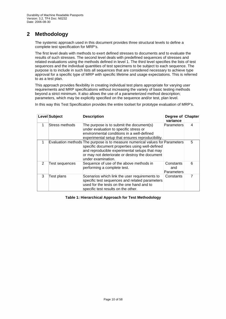
2 Methodology The systemic approach used in this document provides three structural levels to define a complete test specification for MRP’s.
The first level deals with methods to exert defined stresses to documents and to evaluate the results of such stresses. The second level deals with predefined sequences of stresses and related evaluations using the methods defined in level 1. The third level specifies the lists of test sequences and the individual quantities of test specimens to be subject to each sequence. The purpose is to include in such lists all sequences that are considered necessary to achieve type approval for a specific type of MRP with specific lifetime and usage expectations. This is referred to as a test plan.
This approach provides flexibility in creating individual test plans appropriate for varying user requirements and MRP specifications without increasing the variety of basic testing methods beyond a strict minimum. It also allows the use of a parameterized method description; parameters, which may be explicitly specified on the sequence and/or test, plan level.
In this way this Test Specification provides the entire toolset for prototype evaluation of MRP’s.
Level Subject Description Degree of
variance Chapter
1 Stress methods The purpose is to submit the document(s) under evaluation to specific stress or environmental conditions in a well-defined experimental setup that ensures reproducibility.
Parameters 4
1 Evaluation methods The purpose is to measure numerical values for specific document properties using well-defined and reproducible experimental setups that may or may not deteriorate or destroy the document under examination.
Parameters 5
2 Test sequences Sequence of use of the above methods in performing a complete test.
Constants and
Parameters
6
3 Test plans Scenarios which link the user requirements to specific test sequences and related parameters used for the tests on the one hand and to specific test results on the other.
Constants 7
Table 1: Hierarchical Approach for Test Methodology
Each sequence is composed of stress methods and evaluation methods executed in a specific order. A test plan is composed of one or more individual sequence(s) that is linked to a specific set of documents and user requirements.
Stress method
n
Stress method
51 Stress
method 4 Stress
method3 Stress
method 2 Stress
method 1
Evaluationmethod
n
Evaluation method
5 Evaluation
method 4
Evaluation method
3 Evaluation
method 2
Evaluation method
1
Set of Documents
Set of Stress Methods
Set of EvaluationMethods
Set of Test Scenarios with individual sequences of method execution
Figure 1: - Relationship Between Methods, Sequences and Test Plans
References are given to a single MRP. However, multiple MRP samples may be tested simultaneously depending on the size and construction of the test apparatus.
3.2 Preparation
Test samples shall, wherever applicable, be either finished MRP's or be prepared from finished MRP's having passed the entire production process including visual personalisation with a dataset considered typical for the specific type of passport. Initialisation and personalisation of the chip may be done in an arbitrary way as long as the chip is able to support the necessary tests within the intended test sequence.
MRP’s shall be conditioned in accordance with 4.1.
Test pieces shall, as necessary, be prepared from the test samples in the particular form required by the test apparatus used.
3.3 Sampling
In certain cases samples may be taken from the base material before MRP manufacture if it can be demonstrated that no significant change in the property to be tested can arise during subsequent processing. The samples used to prepare a set of test pieces shall be taken from the same batch of MRP base materials.
3.4 Storage
Any test samples or test pieces retained for reference shall be stored under the environmental conditions specified in 4.1 Default Environment.
All such samples shall be clearly cross-referenced to the test report and any relevant supplementary documentation.
Unless otherwise specified, testing shall take place in an environment having a default temperature of 23 °C ± 3 °C (73 F ± 5 F) and relative humidity of 40% RH to 60% RH (ISO/IEC 10373-1).
4.2 Climatic conditions
Climatic conditions defined in the test methods given below are the conditions within the chamber. The resulting temperature in the MRP is not specified or defined in the methods.
4.3 Tolerances
Unless otherwise specified, a tolerance of ± 5% shall be applied to the quantity values given to specify the characteristics of the test equipment (e.g. linear dimensions) and the test method procedures (e.g. test equipment adjustments).
4.4 Default MRP holder
A structure for holding the MRP while maximizing air space around the MRP during testing shall have the general construction as shown in Figure 2. There are no size or quantity limitations for the holder rack, any number of MRP positions may be used.
5 Stress Methods Instructions and methods described below are designed to apply reproducible stresses to the travel document. Instructions and methods that describe how to measure the effect of these stresses are given in 6 Evaluation methods.
The fundamental philosophy behind all stress methods is to define conditions that mimic real daily use (as much as possible). In cases where the correlation between real life and the stress method is tenuous, every attempt has been made to define conditions that produce similar rates of deterioration.
5.1 Conditioning Stress Method
5.1.1 Introduction
The MRP’s to be tested shall be conditioned to the test environment as described below.
5.1.2 Input Parameters
t = time of conditioning. If t is not specified, assume 24 hours.
5.1.3 Apparatus
• Default MRP holder.
5.1.4 Method
• Remove MRP from any box and protective packaging.
• Place MRP in default MRP holder with spine up. MRP shall not be forced open but may open on its own. Minimum spacing between MRP and any other MRP shall be 10 mm in all directions.
• Expose MRP to a temperature of 23 °C ± 3 °C and relative humidity of 40%RH to 60%RH for at least time t.
This stress method subjects the MRP to cycling between two temperature extremes. This stress simulates the thermal shock the MRP could experience due to thermal expansion and contraction of each MRP component. The test is conducted over a short period of time for each stress cycle.
5.2.2 Input Parameters
n = number of cycles
5.2.3 Apparatus
• Two climate controlled chambers. Where applicable, a single fast-response climate controlled chamber may be used in place of a second test chamber.
• Default MRP holder
5.2.4 Method
• Control of relative humidity in the climate chambers is not required for this test.
• Place in a climate controlled chamber at temperature of 77 °C ± 3 °C for 15 minutes.
• Transfer the MRP in the default MRP holder to a second climate controlled chamber held at a temperature of –32 °C ± 3 °C in less than 60 seconds (a transfer time of 15 seconds is recommended). The position of the MRP in the holder should not be modified during the transfer process.
• Subject the MRP to a temperature of –32 °C ± 3 °C for 15 minutes.
• Repeat the process for n cycles as depicted in Figure 3.
• At the end of the cycling process remove MRP and return to the default environment. Leave MRP in holder and condition according to 4.1.
This stress method applies high or low temperature and humidity to the document for specified amounts of time. This stress simulates a document’s exposure to various storage conditions. The purpose of the test is to demonstrate the resistance of MRP construction to such conditions in principle.
The test refers to temperature stability in Doc 9303: “2.4 Temperature stability. The MRP shall remain machine readable at operating temperatures ranging from –10/C to +50/C (14/F to 122/F). The MRP should not lose its reliability after being stored or exposed at temperatures ranging from –35/C to +80/C (–31/F to 176/F).”
Note that extremes of temperature may affect various security features, especially inks. Changes in these features shall not be considered a failure unless they render the document unrecognisable as belonging to the bearer.
5.3.2 Input Parameters
T = temperature at which the passport is stored
H = relative humidity for storage
5.3.3 Apparatus
• Climate controlled chamber.
• Default MRP holder
5.3.4 Method
• Place MRP in climate controlled chamber at temperature T ± 3°C and H Relative Humidity for 168 hours.
This stress method applies high or low temperature and humidity to the document for specified amounts of time. This stress simulates a document’s exposure to various climatic conditions. The purpose of the test is to demonstrate the resistance of MRP construction to such conditions in principle.
The test refers to temperature stability in Doc 9303: “2.4 Temperature stability. The MRP shall remain machine readable at operating temperatures ranging from –10/C to +50/C (14/F to 122/F). The MRP should not lose its reliability after being stored or exposed at temperatures ranging from –35/C to +80/C (–31/F to 176/F).”
Note that extremes of temperature may affect various security features, especially inks. Changes in these features shall not be considered a failure unless they render the document unrecognisable as belonging to the bearer.
5.4.2 Input Parameters
T = temperature at which the passport is expected to operate
5.4.3 Apparatus
• Climate controlled chamber.
• Default MRP holder
5.4.4 Method
• Place MRP in climate controlled chamber at temperature T ± 3°C for 1 hour.
This stress method applies a certain forced impact to the sample to simulate stamping of the document at a border control point.
5.5.2 Input Parameters
S = sheet to be affected by impact. Note, as only visa pages will be impacted, sheet S may not be impacted directly.
5.5.3 Output Parameters
None
5.5.4 Apparatus
• Stamp:
The face of the stamp is a flat solid surface, steel or equivalent, with a diameter 29 mm.
Concentric circles are etched into the surface. The profile of the grooves is rectangular, with a minimum groove depth 0.3 mm. The width of the grooves is 1 mm ± 0.1 mm, and the nominal distance between grooves is 1.5 mm.
The nominal diameter of the central circular groove is 1 mm.
The accumulated tolerances of groove distances is ± 0.5 mm.
Ø 29 mm
Figure 4: Impact Pattern Resulting from Specified Stamp
• The stamp/weight may be constructed as one of:
o Single-piece stamp of mass M
o Stamp that is placed on document and then struck by a weight of mass M.
• Flat surface made of steel at least 12 mm thick with a 2mm rubber blanket
• The rubber blanket shall have a Shore D value of 50.
• Suitable guiding for stamp to maintain stamping face parallel to MRP surface at the point of impact.
• Holder for retaining pages of the MRP against the flat surface during testing.
H = nominal height (mm) from which an impact stamp is dropped onto the document or weight is dropped onto the stamp, thereby defining an impact velocity according to the formula for acceleration of inert bodies under earth gravitation.
H shall be between 0.05 m and 0.20 m
M = weight (kg) of the impact stamp
D = displacement between two impacts
The product P = H·M shall have a value of 0.02 kg·m.
If the apparatus is composed of a stamp that is impacted by a separate weight, the weight shall have mass M, and be dropped from a height H above the stamp. The mass of the stamp is not considered.
5.5.5 Method
• Locate the sheet S.
• Locate the nearest visa page that could require stamping and turn this over on top of the sheet under test. Depending on location, it is possible that there could be several sheets between the sheet S and the nearest visa page.
• Open MRP to 180 degrees and place on flat hard surface covered with a rubber coating so the outer cover is directly against the flat surface.
• Drop impact stamp of mass M from a height H at each of the locations as shown in Figure 5. Move from first to last location progressing from left to right and from top to bottom.
• If there are visa pages that could require stamping on the opposite side of the sheet under test, repeat the above process on the other side, but using a different MRP.
10.5 (9X)
10.5 (5X)
1st stamping location dimensions in mm
71
9th stamping location
Last stamping location
113
3
3
Figure 5: Impact stamp locations
5.5.6 Alternate Method
• If the fragile area is obvious it is acceptable to exclude drops that do not impact this obvious area.
This test simulates on the stresses of sitting on a MRP, This method applies a force to the MRP and forces it to bend around a curved surface. The resulting stresses acting on the MRP are a combination of compression and bending stresses.
5.6.2 Input Parameters
n = number of cycles to apply force
5.6.3 Output Parameters
None
5.6.4 Apparatus
• A test apparatus to load the MRP in a manner consistent with Figure 6 below.
• An anvil with spherical impact area of radius r = 150 mm.
• A cushion having elastic properties equivalent to an air cushion inflated to a pressure of 30 kPa, or to foam having density of 40-50 g/l and hardness of 20-30 kg/cm2 as defined in ISO 2439. The minimum thickness of the cushion is 0.1 m. The minimum dimension, in any direction, of the cushion surface on which the sample is placed shall be be larger than 0.2 m and shall be larger than the anvil.
• Notes: The test results do not depend on the exact properties of the cushion as long as (a) its resistance to the force exerted by the sample under the anvil is sufficient to so that the force is not deviated from the sample (i.e. the activated anvil shall not touch the cushion directly as long as the bending of the sample is not entirely following the anvil shape), (b) its elasticity is sufficient to follow the anvil shape without irregular deformations, and (c) its resistance to the exerted pressure is not subject to local deviations or irregularities.
Radius r Anvil
Elastic cushion
Sample
Figure 6: Schematic of the test apparatus to load the MRP in the Back Pocket Bending Method
5.6.5 Method
• Place and center the MRP with respect to the cushion and the spherical anvil.
• Secure the MRP on the test machine so that the centered placement can be maintained during testing. A flexible support pocket constructed from fabric such as denim may be used.
The purpose of this test is to determine the bending fatigue resistance of the booklet construction to fully reversed loading. This method differs from the back pocket stress method by avoiding directly applied pressure. This method accelerates fatigue due to imposed bending, especially in the area of the antenna and associated connections if present.
5.7.2 Input Parameters
n = Number of bending cycles with the MRP
O = orientation of book in the bender
5.7.3 Output Parameters
None
5.7.4 Apparatus
• Dynamic flexion machine as illustrated below.
Pushing rollers D1 23 mm diameter
Edge of MRP clamped in pivoting holder
Fixed rollers D2 20 mm diameter
D1
D2
H1 = 35 mm
H2
L2 = 30 mm
L1 = 55 mm
Figure 7: Apparatus to impose cyclic motion
• The pushing rollers shall be set to ensure that the centreline deflection of the MRP is equal on
each segment of the stroke.
• The distance H2 between the clamped edge of the MRP and the pushing rollers on center is adjustable between 40 and 58 mm.
• Pushing rollers and fixed rollers are separated by 35 mm (H1) on center.
• Pushing rollers have an outer diameter D1 of 23 mm and are separated by 55 mm (L1) on center.
• Fixed rotating rollers are separated by a distance of 30 mm (L2)on center and have an outer diameter D2 of 20 mm.
• Taking into account, the specified orientation, O, the MRP shall be clamped at one extremity and allowed to freely move at the opposite edge.
• H2 should be adjusted depending on the orientation of the book
Orientation (O) H2
Spine clamped 40 mm
Top clamped 58 mm
• Move the pushing rollers so that they just push the passport up against the fixed rollers without bending the passport as illustrated below. The amount of roller movement is b0 and is called the initial position.
b0
Figure 8: Initial position of Pushing Rollers
• Allow the pushing rollers to move freely, however set the maximum travel of the pushing rollers to b0 + 20 mm.
• Apply a force of 40 N in the direction of the bold arrow in Figure 9 for 1 minute.
• Measure the amount of travel of the pushing rollers. If the maximum travel is reached with a force of less than 40 N then the travel to be used for the test is b = b0 + 20 mm; otherwise measure the amount of travel of the pushing rollers, b, as shown in the figure above.
• Remove 40 N load.
• Note, alternate equipment may be used for calibration.
5.7.6 Method
• Set the travel of the pushing rollers to ±b as measured above.
• Flex the book n times at 0.5 Hz. One cycle is a one deflection in each direction.
The purpose of this test is to determine adverse mechanical or functional effects in the MRP arising from torsional fatigue. This method differs from the back pocket stress method by applying only torsional stresses to the MRP.
5.8.2 Input parameters
n = Number of torsion cycles
5.8.3 Output parameters
None
5.8.4 Apparatus
• The test apparatus shall impose torsional motion in a manner consistent with Figure 10 shown below.
d = 127 mm
10 mm
Thickness of booklet + 0.5 mm
B A
Guide rails
+R +R
-R -R
C
Fixing point for booklet
R = Angle of rotationn
Figure 10: Schematic of the apparatus and the associated motion for torsion
5.8.5 Calibration
• Adjust separation of guide rails to thickness of book plus a maximum of 1 mm.
• Place MRP in test apparatus
• Set maximum travel of holders to 15 degrees.
• Apply a torque of 0.3 N-m for 1 minute.
• Measure amount of travel and reset maximum travel, R, of holder to amount measured.
The purpose of the test is to determine the folding resistance of a sheet of a machine readable passport (MRP) at the spine.
5.9.2 Input Parameters
P = Sheet under test
n = Number of cycles
5.9.3 Output Parameters
None
5.9.4 Apparatus
• Fixture for clamping the fixed sheet or MRP
• Arm for rotation of sheet or MRP
• Device to apply force to sheet or MRP being tested.
• Note that no constraints are placed on machine design, including which clamp is fixed, which clamp moves, and which clamp force the force is applied to.
• Note also that the apparatus should prevent bending of the booklet in any other place than the axis of the booklet spine.
5.9.5 Method
• The entire book except the sheet to be tested is folded back and held in a clamp. The sheet to be tested is held in another clamp allowing for the rotation of the sheet or MRP under test around the spine between the defined angle positions:
F
0°
+90- 90°
F
0°
+90-90°
Figure 11: Sheet Bending Illustration
• Bending Parameters
o Bending frequency: f = 0.5 Hz
o Bending angle: a = ± 90°
o Tensile force: F= 1 N/cm ± 25% (force per length of sheet)
The purpose of the test is to determine the tearing resistance of the booklet pages and the sewing part during the usage of a machine readable passport (MRP).
5.10.2 Input Parameters
P = Sheet under test
5.10.3 Output Parameters
S = Maximum tearing strength in N/cm
5.10.4 Apparatus
• Clamp to hold MRP in a fixed position, minimum width of clamping area 130 mm
• Movable clamp for pulling on the page under test, minimum width of clamping area 130 mm
5.10.5 Method
• Cut the opposite sheet of the one under test. The cutting distance from the spine should be of 10 mm.
• Place all the other sheets including cover in the fixed clamp of the apparatus.
• The fixed clamp shall be set at a distance from the spine so that it does not clamp any portion of the sheet under test.
• Apply a force of 60 N at a maximum velocity of 5 mm/s.
The purpose of this test is to determine the effect of a specified mechanical abrasion to the Passport Data Page of an ICAO-compliant document. The main purpose is to test the machine-readable zone (MRZ) but the test might also be used for the Visual Inspection Zone (VIZ) or visa entries (sticker) of the passport. In order to perform this test, the datapage (visa page) shall be personalized.
The abrasive material to be used should be the material of the facing page.
5.11.2 Input Parameters
n = number of test cycles (double strokes)
5.11.3 Output Parameters
None
5.11.4 Apparatus
test load L = 14000 ± 5 % N/m2
length (or diameter) of test load D = 15 mm (width shall cover MRZ)
test speed v = between 2.5 and 25 cm/s
• The abrasive material has to be attached to the test load without protruding beyond the edge of the passport. If increased adhesion is required a double sided adhesive tape can be used.
• Test Load Movement: -The abrasion axis is parallel to the MRZ of the MRP. The amplitude of the test load movement shall cover at least 20 mm. Test equipment may move/rotate the test load during the test between cycles.
P<UTOERIKSSON<<ANNA<MARIA<<<<<<<<<<<<<<<<<<<
L898902C<3UT06908061F9406236ZE184226B<<<<<14
MRZ Axis of test load movement
Figure 13: Illustration of the Abrasion Test
5.11.5 Method
• Fix the Passport Data Page on a level rigid plate (i.e. sample carrier of the test equipment). Apply the test load and start the apparatus at specified speed and amplitude for the specified number of test cycles.
• Alternative equipment may be used as long as it provides equivalent results (e.g. Taber method from ISO 9352 using CS10F wheel).
The purpose of the test is to simulate writing over the PIC with a ball point pen simulating manual entries on visa pages. It is felt that depending on the construction of the passport, a pen might damage components of the passport (IC, inlay or paper).
The page to be written on shall be one that is normally written on and shall provide maximum stress to the chip (if present). In the case where it is possible to write on pages on both sides of the chip sheet, separate MRP’s should be evaluated.
Note, this method may not be suitable when devices like rivets are used. I.e. the pen may become damaged or stuck if features protrude from the page under test.
5.12.2 Input parameters
n = number of cycles
P = page to test
5.12.3 Output parameters
None
5.12.4 Apparatus
• Pen with ball point of diameter 0.7 mm compliant with ISO 12757-2.
• Pen positioning apparatus capable of pen movement in X and Y direction over the area shown in Figure 14. Pen shall be held at an angle of 90 degrees to the page under test.
5.12.5 Method
• Choose a Page P to write on. It shall be a Page that is normally written on and shall provide maximum stress to the chip. In the case where it is possible to write on pages on both sides of the chip page, both sides will be tested.
• Clamp MRP in suitable holding fixture so pages do not move during testing.
• Apply a load to pen of 250 g downward toward pages under test.
• Apply a series of strokes, each in the form of a double line (movement back and forth along the same straight line and across the dimension of the sample) and at a nominal distance of 1.5 mm between lines.
• Move pen with a maximum speed of 150 mm/sec from left to right and back again on the same
line as shown in Figure 14 for lines in the long direction.
• When the pen has returned to the starting point, move to the next line as shown. It is not necessary to lift the pen when moving from one line location to the next.
• After completing the last line in the long direction, begin to make lines in the short direction.
• Move pen with a maximum speed of 150 mm/sec from bottom to top and back again on the same line as shown in Figure 14 for lines in the short direction.
• When the pen has returned to the starting point, move to the next line as shown. It is not necessary to lift the pen when moving from one line location to the next.
• Replace pen as soon as ink is exhausted, lines shall not be made with no ink.
• Outer margin of 5 mm from the edge of the page under test may be disregarded. This margin may be used to stabilize the page under test by e.g. clamping or taping it to the support.
• The surface coverage may be reached in a single run or by consecutive runs covering sub-areas of the page under test.
• Repeat the sequence n times.
• If critical areas are obvious, the pen test may be performed only over those areas.
The purpose of this test is to determine any adverse effects of a range of chemical contaminants on an MRP test sample. It is possible that the document may not be useable for travel after this test, but it is expected that the book shall be identifiable as belonging to the bearer.
Certain security features incorporated into MRP’s are designed to react to reagents in order to show taat tampering has taken place. The action of these security features under the influence of the reagents shall not constitute a failure.
5.13.2 Input Parameters
None
5.13.3 Output Parameters
None
5.13.4 Apparatus
• MRP holder
• Solutions as required
5.13.5 Short Term Contamination Test
5.13.5.1 Short Term Reagents (list provided here for information only, defined in ISO/IEC 10373-1)
a) 5% by mass aqueous solution of sodium chloride (NaCl, 98% minimum assay);
b) 5% by mass aqueous solution of acetic acid (CH3COOH, 99% minimum assay);
c) 5% by mass aqueous solution of sodium carbonate (Na2CO3, 99% minimum assay);
d) 60% by mass aqueous solution of ethyl alcohol (CH3CH2OH, 93% minimum assay);
e) 10% by mass aqueous solution of sucrose (C12H22O11, 98% minimum assay);
f) Fuel B (according to ISO 1817);
g) 50% by mass aqueous solution of ethylene glycol (HOCH2CH2OH, 98% minimum assay).
5.13.5.2 Short Term Contamination Method • Use solutions as defined in ISO/IEC 10373-1.
• Use a different sample MRP for each solution.
• Prior to immersion in the test solution, fan the pages of the MRP such that the sheets of the MRP are exposed.
• Standing the MRP upright (spine is in a vertical orientation), submerge the MRP for 60 seconds in one of the solutions listed above. The solutions shall be kept at a temperature between 20 °C and 25 °C.
• Remove MRP from solution and place in default MRP holder for 24 hours at default temperature and humidity conditions. For those samples immersed in organic solvents (including fuel), this procedure should be performed within the confines of a fume hood.
5.13.6 Long Term Contamination Test
Page 32 of 58
5.13.6.1 Long Term Reagents (list provided here for information only, defined in ISO/IEC 10373-1)
b) artificial perspiration (both solutions shall be prepared in accordance with ISO 105-E04:1994): (i) alkaline solution; (ii) acid solution.
5.13.6.2 Method for Salt Mist • Use neutral solution as defined in ISO/IEC 10373-1.
• Use a different sample MRP for each test.
• For the salt mist exposure, mount the sample MRP vertically in a cabinet in accordance with ISO 9227:1990 for 24 hours.
• Remove MRP from solution and place in default MRP holder for 24 hours at default temperature and humidity conditions.
5.13.6.3 Method for Synthetic Perspiration • The filter paper shall be compliant with ASTM E 832. Any Type I filter paper for qualitative
analysis may be selected.
• Soak filter paper in the artificial perspiration solution. Allow excess liquid to drain for 10 seconds then place it on a flat non-absorbent surface (glass plate) to stabilise for 1minute.
• Wrap the sample MRP in the wetted filter paper and place this in a sealed plastic bag in an environment kept between 20 °C and 25 °C. The plastic bag shall be placed between flat plates with a 5 kg weight positioned on top.
• Leave the sample in this environment for 24 hours.
• Remove MRP from solution and place in default MRP holder for 24 hours at default temperature and humidity conditions.
This test is derived from ISO 105-B02 and exposes the sample to illumination from an artificial light source that represents natural daylight in the visible and near UV (UV A) spectral region. The aim of this test is to assess the resistance of the MRP to fading.
Note: The blue wool reference numbers refer to those preferred in Europe (1-8) and not those preferred in the US (L2-L9)
Note that this method is difficult to apply to ordinary security printing backgrounds due to the fine structure of the linework. It is acceptable to print samples using test patterns for each ink used in production to facilitate this test.
5.14.2 Input Parameters
P = page to expose
S = blue wool scale to measure exposure
5.14.3 Output Parameters
None
5.14.4 Apparatus
• An air-cooled xenon arc lamp apparatus with a well-ventilated exposure chamber and a xenon arc lamp of correlated colour temperature 5500 K – 6500 K shall be used. A light filter (glass filter) placed between light source and samples shall cut all radiation with wavelengths smaller than 310 nm. A heat filter placed between light source and samples shall be used in order to reduce IR radiation contained in the xenon arc spectrum.
5.14.5 Method
• Cut a sample from the MRP to required size for the test machine and place an opaque cover over a portion of the sample (for comparison purposes)
• Prepare the appropriate blue wool reference in the same way. Strips cut from the blue wool references 1 to S shall be used.
• Place samples together with the blue wool reference set in the accelerated daylight test apparatus and expose to artificial daylight according to Method 2 (ref. ISO 105 B-02) until the exposed part of the blue wool reference S has faded to the equivalent of gray scale 4
The purpose of this test is to determine any adverse effects to the MRP by X-rays levels that might be encountered during border control screening. The MRP shall comply with the requirement in ISO/IEC 7816-1 when tested in accordance with ISO/IEC 10373-1.
5.15.2 Input parameter
None
5.15.3 Output Parameter
None
5.15.4 Apparatus
• Use apparatus defined by ISO/IEC 10373-3 for X-rays.
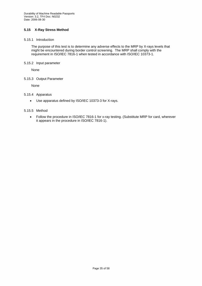
5.15.5 Method
• Follow the procedure in ISO/IEC 7816-1 for x-ray testing. (Substitute MRP for card, wherever it appears in the procedure in ISO/IEC 7816-1).
6 Evaluation methods Evaluation methods are instructions describing how to measure specific attributes of the passport. Wherever applicable, the output of the evaluation method should be a numerical value that can be compared against a pass/fail criterion.
6.1 Functional PIC Evaluation Method
6.1.1 Introduction
This method evaluates the function of the Proximity Integrated Circuit (PIC). The method determines that chip is still sane and that it operates within normal and reasonable conditions. There is always a tradeoff between the execution time of this method and the completeness of the test.
If the MRP does not contain a chip, this evaluation method returns a Pass result.
6.1.2 Input Parameters
None
6.1.3 Output Parameters
R = Pass/Fail
6.1.4 Apparatus
• Commercial PIC reader.
6.1.5 Method
• Evaluate the PIC as per reference [9], RF Protocol and Application Test Standard for e-Passport – Part 2, WG3TF4_N0163, Version 0.9, 2006-02-10, section C.2.
The intent of this method is to verify that the passport is (still) suitable for use as a travel document. To pass the evaluation method, the document shall be intact, and shall still be machine readable. Some security features may be degraded or altered, however, the evaluation of these features may be subjective and specific to individual passports and are therefore outside the scope of this method.
6.2.2 Input Parameters
None
6.2.3 Output Parameters
R = Pass/Fail
6.2.4 Apparatus
None
6.2.5 Method
Physical damage and related acceptability levels are best evaluated by comparing the sample(s) under test to a set of evaluation samples that is considered to be just at the limit of acceptability. However as the authors need to put something prescriptive on paper, the following limits should be placed on a MRP for it to be useable. Future versions of this document will hopefully contain a more complete list of requirements. • The picture shall be reconizeable.
• Written information shall be legible, with no missing letters or words.
• The MRZ shall be machine readable.
• The MRP shall be Intact – no pages shall be separated.
• Opening the MRP to the datapage (180 degrees) shall not incur any further damage.
• opening the MRP to a visa page (180 degrees) shall not incur any further damage.
• The PIC containing part (Cover, Data Page, Special visa page) does not allow direct access to the chip or the antenna.
• No part of the datapage shall be missing.
• For datapages, more than 90% of the binding shall be intact.
• For other pages, more than 50% of the binding shall be intact.
• At least 50% of the hot-stamp on the cover shall be intact.
• Any holes in any sheets shall be less than 2mm in diameter.
• Areas of delamination along the edges shall be less than 3 mm deep, and 3 mm in length. Delaminations within the sheet shall be less than 3 mm in length.
The purpose of this test is to measure the peel strength between different layers used in passport constructions according to ISO/IEC 10373-1/5.3.
If the sheet to be evaluated is composed of multiple layers, the peel strength evaluation should be conducted on all layers. A separate document should be used for each layer so that a consistent number of strips will be cut from the sheet.
6.3.2 Input Parameters
P = sheet to perform test on
6.3.3 Output Parameters
F = strength (N/mm)
6.3.4 Apparatus
• Use apparatus defined in ISO/IEC 10373-1 Peel test method. References to “card” shall mean “sheet” for this test. If a stabilizing plate is required, a suitable size would be 95 mm x 130 mm.
6.3.5 Method
• Remove the sheet to be tested from the MRP
• Follow the method for peel strength measurements as outlined in ISO/IEC 10373-1, Peel test method, except for preconditioning and the direction and quantity of sample sections.
• Following Figure 15, cut the sample, or score through the layer, to produce sections of width 10.0 mm ± 0.2 mm. The top reference edge is the edge closest to the spine
This evaluation method determines the change in appearance of the sample following exposure to artificial daylight. This evaluation method relies on the sample being subjected to 5.14 Artificial Daylight Exposure Stress Method.
6.4.2 Input Parameters
P = Page to evaluate
6.4.3 Output Parameters
R = Pass/Fail
6.4.4 Apparatus
None
6.4.5 Method
• Colour fastness evaluation derived from ISO 105-B02.
• The evaluation procedure is as follows:
• Visually evaluate fading or colour changes. For this purpose samples shall be illuminated by a D65 light source.
• Compare the contrast between exposed and unexposed sample with the contrast of gray scale 4.
• If the sample contrast is higher then the test result is Fail. If the sample contrast is less or equal then the test result is Pass.
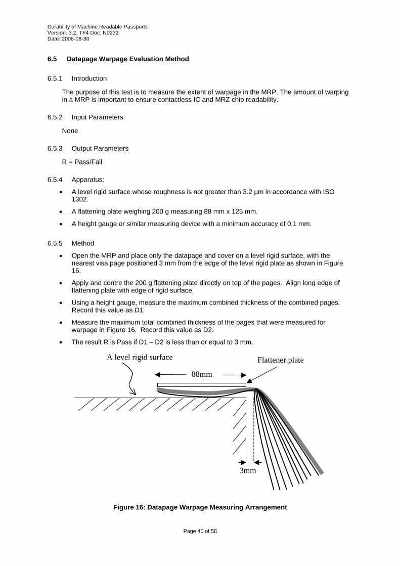
The purpose of this test is to measure the extent of warpage in the MRP. The amount of warping in a MRP is important to ensure contactless IC and MRZ chip readability.
6.5.2 Input Parameters
None
6.5.3 Output Parameters
R = Pass/Fail
6.5.4 Apparatus:
• A level rigid surface whose roughness is not greater than 3.2 µm in accordance with ISO 1302.
• A flattening plate weighing 200 g measuring 88 mm x 125 mm.
• A height gauge or similar measuring device with a minimum accuracy of 0.1 mm.
6.5.5 Method
• Open the MRP and place only the datapage and cover on a level rigid surface, with the nearest visa page positioned 3 mm from the edge of the level rigid plate as shown in Figure 16.
• Apply and centre the 200 g flattening plate directly on top of the pages. Align long edge of flattening plate with edge of rigid surface.
• Using a height gauge, measure the maximum combined thickness of the combined pages. Record this value as D1.
• Measure the maximum total combined thickness of the pages that were measured for warpage in Figure 16. Record this value as D2.
• The result R is Pass if D1 – D2 is less than or equal to 3 mm.
The purpose of this test is to measure the extent of warpage in the MRP. The amount of warping in the MRP is important to ensure contactless IC chip readability. This method is similar to the Datapage Warpage Evaulation Method but measures the amount of warpage with the MRP in the closed position.
6.6.2 Input Parameters
None
6.6.3 Output Parameters
R = Pass/Fail
6.6.4 Apparatus:
• A level rigid surface whose roughness is not greater than 3.2 µm in accordance with ISO 1302.
• A flattening plate weighing 200 g measuring 88 mm x 125 mm.
• A height gauge or similar measuring device with a minimum accuracy of 0.1 mm.
6.6.5 Method
• Measure the maximum thickness of the MRP. Record this value as D1.
• Place the closed MRP on a level rigid plate.
• Center the 200 g flattening plate directly on top of the MRP.
• Using a height gauge, measure the maximum height of the MRP. Record this value as D2.
• The result R is Pass if D2 – D1 is less than or equal to 10 mm.
Sequences are defined to specify the order in which stress methods and evaluation methods are to be performed in order to execute a specific test.
7.2 Instructions for using the Sequence Table
The headings of a sequence table is reproduced below:
Step No.
S/E
Method Parameters Output Parameters Measured
Pass/Fail Criteria
This table defines the order of the methods to be performed. The content of each column is defined below.
Step No. The reference number for the step within the sequence. The order of the methods within the sequence table determines the order in which the methods are to be executed – not the step number.
S/E Indicates whether the method is a Stress method or an Evaluation method.
Method The name of the method to be performed
Parameters Defines the values of the input parameters. Method parameters not assigned at the sequence level shall be assigned at the test plan level.
Output Parameters List of the output parameters of the method that will be used to determine the pass/fail criteria for the test.
Pass/Fail Criteria Specifies the limits of the output parameter that will be considered a Pass for the test sequence.
The purpose of this tests sequence is to simulate normal book handling over its lifetime. Real-life stresses include opening and closing the book and manipulating data and visa pages.
7.3.2 Input Parameters
n = Number of sheet bend cycles
P = Sheet to test
7.3.3 Output Parameters
R = Pass/Fail
7.3.4 Sequence
Step No.
S/E
Method Input Parameters
Output Parm. Measured
Pass/Fail Criteria
1 S 5.1 Conditioning Stress Method - - - 2 S 5.9 Sheet Turning Stress Method P, n - - 3 E 5.10 Sheet Pull Stress Method P S S > 5 N/cm 4 E 6.2 Physical Damage Evaluation
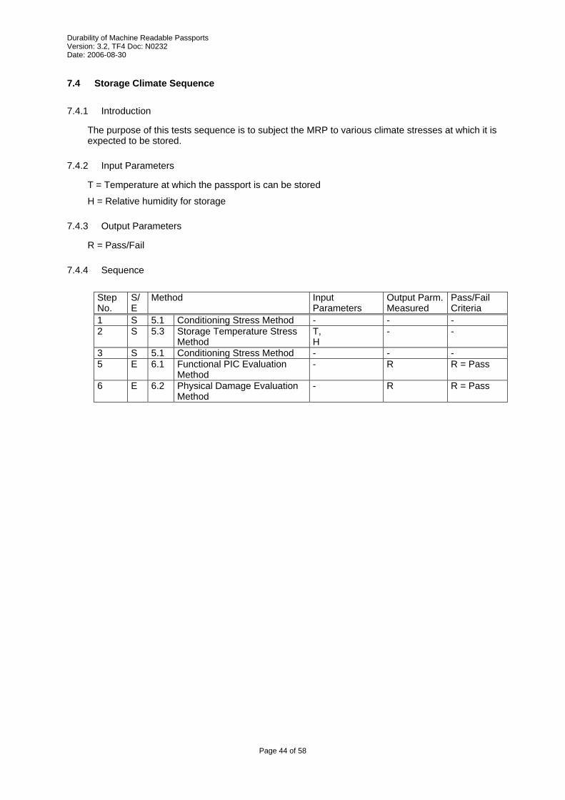
The purpose of this tests sequence is to subject the document to simulated back-pocket stresses. Note that the number of cycles is quite low as sitting on a passport is considered accidental in “normal use”.
7.7.2 Input Parameters
None
7.7.3 Output Parameters
R = Pass/Fail
7.7.4 Sequence
Step No.
S/E
Method Input Parameters
Output Parm. Measured
Pass/Fail Criteria
1 S 5.1 Conditioning Stress Method - - - 2 S 5.6 Book Bend Stress Method
This sequence subjects passports to a range of chemicals that are commonly found in day-to-day situations.
Normally, a sequence would be applied in exactly the same manner to all samples. However for editorial convenience, this sequence covers all of the different solutions, and therefore will require at least 10 passport samples for evaluation.
7.13.2 Input Parameters
None
7.13.3 Output Parameters
R = Pass/Fail
7.13.4 Sequence
Step No.
S/E
Method Input Parameters
Output Parm. Measured
Pass/Fail Criteria
1 S 5.1 Conditioning Stress Method - - - 2 S 5.13 Resistance to chemicals
The purpose of this tests sequence is to simulate writing on the passport. As currently defined, the pen test may be destructive to the visa page; therefore, only the chip is evaluated.
7.14.2 Input Parameters
None
7.14.3 Output Parameters
R = Pass/Fail
7.14.4 Sequence
Step No.
S/E
Method Input Parameters
Output Parm. Measured
Pass/Fail Criteria
1 S 5.1 Conditioning Stress Method - - - 2 S 5.12 Pen Stress Method n =1
P = writeable page nearest chip (both sides if possible)
The test plan is the top level of the test specification. It specifies values for any undefined sequence parameters, and defines the number of books that need to be subjected to each sequence.
Different test plans are defined depending on what is being tested and why. The default test plan is the “minimum durability required by ICAO”. Other test plans can be defined that might set other requirements. For example a 10-year normal use book, or a 5-year heavy use book
Each Lot is composed of new books. Books from one lot shall not be used in the test sequence of another lot.
The lot sizes specify the minimum number of books to be subjected to the test sequence. In general, small lot sizes do not give good statistical results, however very large lot sizes can become expensive to produce and to test. Only absolute minimums are given here. The customer and the tester are free to agree on other lot sizes that are larger than the minimum.
The reader is again reminded that this document is designed to provide a method of prototype testing (Type Approvals). It is not intended to be used to determine if individual documents meet specific standards.
The tester is reminded that while book manufacturers strive for perfect quality, it is possible that faulty samples may be subjected to testing. In the case of a failure, the tester should evaluate the failure, and in consultation with the manufacturer, should decide whether to select another sample for testing.
This test plan specifies the list of test sequences that shall be passed in order for the document to be considered to meet ICAO’s minimum durability level.
Lot No.
Minimum Lot Size
Sequence Parameters
1 3 7.3 Sheet Binding Sequence P = cover n = 1000
2 3 7.3 Sheet Binding Sequence P = datapage n = 1000
3 3 7.3 Sheet Binding Sequence P = visa page n = 1000
4 3 7.3 Sheet Binding Sequence P = chip page n = 1000


![MACHINE READABLE TRAVEL DOCUMENTS...Version 1.01, February 2007 [R9] ICAO Technical Report “Supplemental Access Control for Machine Readable Travel Documents”, Version 1.01, November](https://static.documents.pub/doc/80x56/5e590e40578c8213603904e9/machine-readable-travel-documents-version-101-february-2007-r9-icao-technical.jpg)


