1 st IPAC 2010, Kyoto, 23-28 May 2010 International Energy Related Developments ITER & IFMIF Norbert Holtkamp Principal Deputy Director General 28 May 2010 Thanks to ITER Organization, Domestic Agencies, IFMIF/EVEDA Design Team and the
Transcript
1st IPAC 2010, Kyoto, 23-28 May 2010Page 1
International Energy Related Developments ITER & IFMIF
Norbert HoltkampPrincipal Deputy Director General
28 May 2010
Thanks to ITER Organization, Domestic Agencies, IFMIF/EVEDA Design Teamand the
1st IPAC 2010, Kyoto, 23-28 May 2010Page 2
Contributions to this Conference• [1] N. Holtkamp, “International Energy
Related Developments, ITER and IFMIF”, these proceedings.
• [2] C. Vermare et al. “Commissionning of the IFMIF/EVEDA Accelerator Prototype Objectives, Organization and Plans”, these proceedings.
• [3] R. Gobin et al. “General design of the IFMIF deuteron injector: source and beam line”, Proc. of ICIS’09, Gatlinburg Tennessee, USA.
• [4] M. Comunian, A. Pisent, E. Fagotti, “The IFMIF-EVEDA RFQ: Beam Dynamics Design”, proc. of LINAC’08, Vancouver, Sept. 2008.
• [5] A. Pepato et al, “Engineering Design and First Prototype Tests of the IFMIF-EVEDA RFQ”, these proceedings.
• [6] S. Maebara, “Design of an RF Input coupler for the IFMIF/EVEDA RFQ”, these proceedings.
• [7] F. Orsini et al, “Study and Realization of the First Superconducting Half Wave Resonator Prototype for the SRF Linac of the IFMIF Project”, these proceedings.
• [8] H. Jenhani et al, “Status of the CW RF Power Couplers for the SRF Linac of the IFMIF Project”, these proceedings.
• [9] F. Toral et al, “Calculation and Design of the Magnet Package in the Superconducting SRF Linac of IFMIF”, these proceedings.
• [10] N. Grouas et al, “Mechanical and Cryogenic System Design of the 1st Cryomodule for the IFMIF Project”, these proceedings.
• [11] D. Regidor et al, “IFMIF/EVEDA RF Power System”, these proceedings.
• [12] C. Oliver et al, “Magnet Design for the Medium and High Energy Beam Transport Lines of the IFMIF-EVEDA Accelerator”, these proceedings.
• [13] C. Oliver et al, “Alignment and Magnet Error Tolerances for the HEBT Line for the IFMIF-EVEDA Accelerator”, these proceedings.
• [14] H. Takahashi et al, “Present Status of the Development of MPS and TS for IFMIF/EVEDA Accelerator Prototype Control System”, these proceedings.
1st IPAC 2010, Kyoto, 23-28 May 2010Page 3
Fusion powers the sun and the starsFusion powers the sun and the stars“…“…Prometheus stole the fire from the heavenPrometheus stole the fire from the heaven””
• Essentially limitless fuel, available all over the world
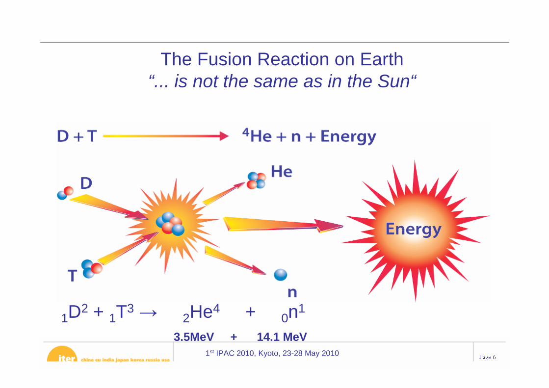
The Fusion Reaction on Earth“... is not the same as in the Sun“
1D2 + 1T3→ 2He4 + 0n1
3.5MeV + 14.1 MeV
1st IPAC 2010, Kyoto, 23-28 May 2010Page 7
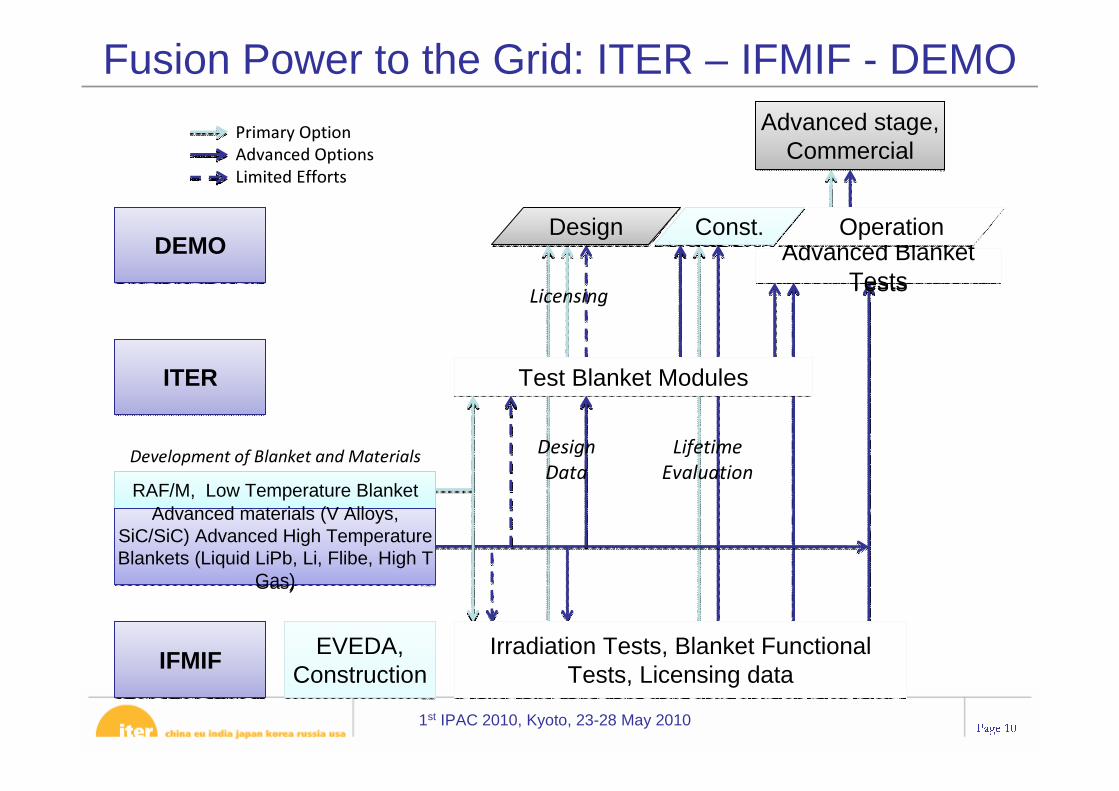
• Technology → ITER• Materials → IFMIF• Fuel (Tritium Production) → Test Blankets• Reactor Concept Development → DEMO
The Goal: A Fusion Power Plant
1st IPAC 2010, Kyoto, 23-28 May 2010Page 8
Lithium compound
Not to scale !
The Goal: A Fusion Power Plant
1st IPAC 2010, Kyoto, 23-28 May 2010Page 9
• operationally, it is essentially an electrical transformer
• toroidal magnetic field is produced by external magnetic field coils
• plasma current produces poloidal magnetic field
• result is a set of nested helical surfaces⇒ plasma confinement
The Tokamak concept
1st IPAC 2010, Kyoto, 23-28 May 2010Page 10
Development of Blanket and Materials
Licensing
Design
Data
Lifetime
Evaluation
DEMODEMO
ITERITER
Advanced Blanket Tests
Advanced Blanket Tests
Advanced stage, Commercial
Advanced stage, Commercial
RAF/M, Low Temperature BlanketRAF/M, Low Temperature BlanketAdvanced materials (V Alloys,
SiC/SiC) Advanced High Temperature Blankets (Liquid LiPb, Li, Flibe, High T
Gas)
Advanced materials (V Alloys, SiC/SiC) Advanced High Temperature Blankets (Liquid LiPb, Li, Flibe, High T
Gas)
IFMIFIFMIF EVEDA, Construction
EVEDA, Construction
Irradiation Tests, Blanket Functional Tests, Licensing data
Irradiation Tests, Blanket Functional Tests, Licensing data
Test Blanket ModulesTest Blanket Modules
Primary Option
Advanced Options
Limited Efforts
DesignDesign Const.Const. OperationOperation
Fusion Power to the Grid: ITER – IFMIF - DEMO
1st IPAC 2010, Kyoto, 23-28 May 2010Page 11
ITER -the way to fusion energy
1-3 dpa1-3 dpa < 150 dpa< 150 dpa
1st IPAC 2010, Kyoto, 23-28 May 2010Page 12
The Way to Fusion Power – The ITER (Hi-)story
The idea for ITER originated from the Geneva Superpower Summit in 1985 where Gorbachev and Reagan proposed international effort to develop fusion energy…
…“as an inexhaustible source of energy for the benefit of mankind”.
“For the benefit of mankind ”
November 21, 2006: China, Europe, India, Japan, Korea, Russian Federation and the United States of America sign the ITER Agreement
• The ITER Organization and the ITER Domestic Agencies: 80% of the ITER construction is “In-Kind”
1st IPAC 2010, Kyoto, 23-28 May 2010Page 22
ITER ITER –– Key FactsKey Facts• Mega-Science Project among 7
Members: China, EU, India, Japan, Korea, Russia & US
• 10 years construction, 20 years operation
• Cost: ~5.6 billion Euros approved for construction, and ~5.5 billion for operation and decommissioning
• EU 5/11, other six parties 1/11 each. Overall reserve of 10% of total.
European Union
CN
IN
RF
KO
JP
US
1st IPAC 2010, Kyoto, 23-28 May 2010Page 23
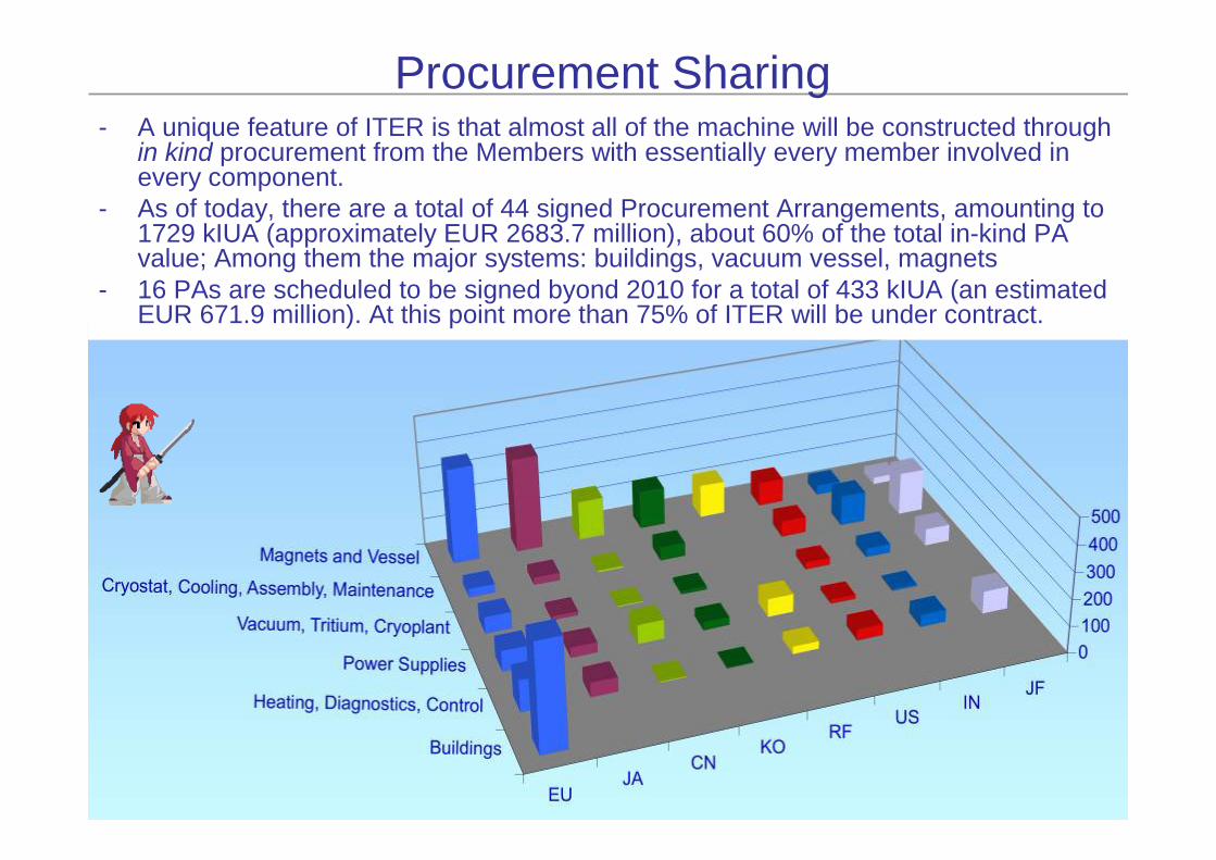
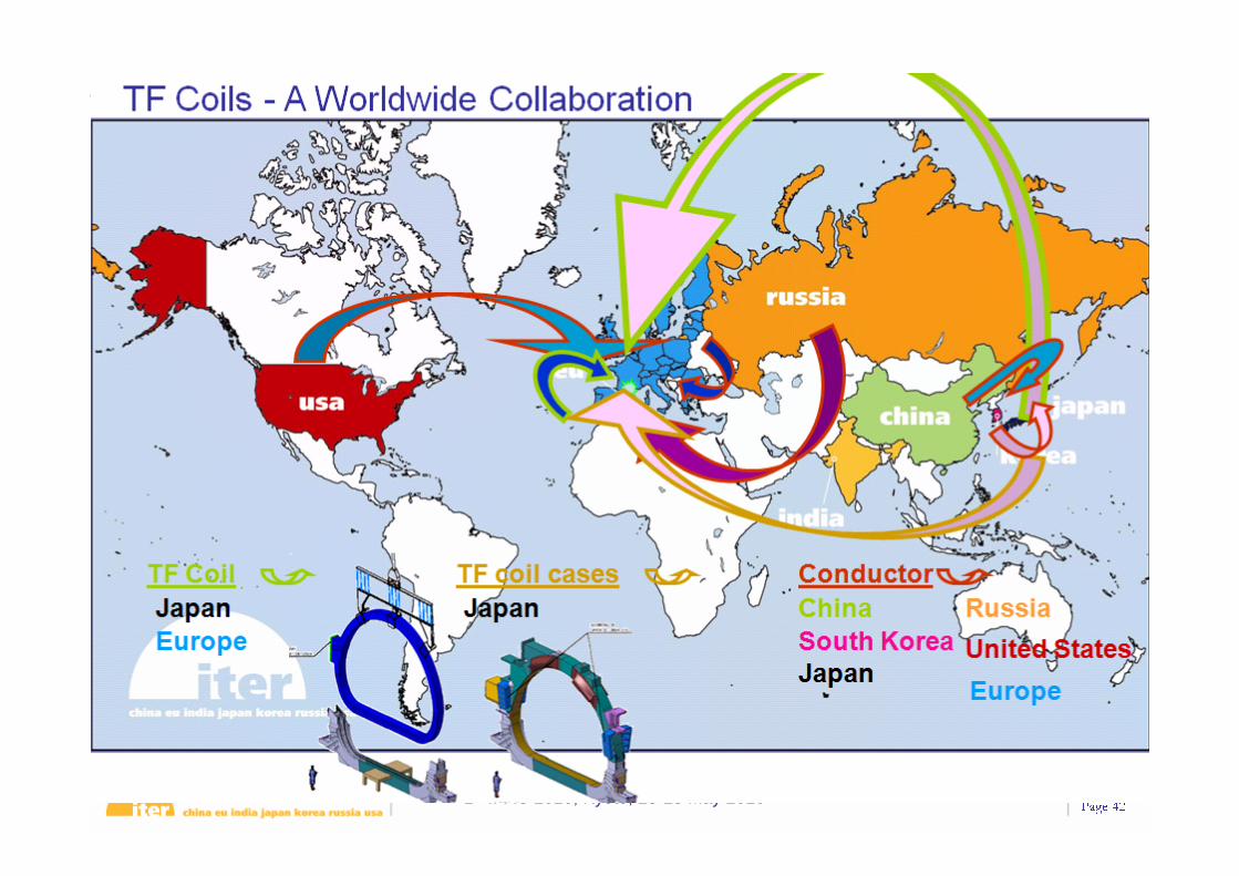
Procurement Sharing- A unique feature of ITER is that almost all of the machine will be constructed through
in kind procurement from the Members with essentially every member involved in every component.
- As of today, there are a total of 44 signed Procurement Arrangements, amounting to 1729 kIUA (approximately EUR 2683.7 million), about 60% of the total in-kind PA value; Among them the major systems: buildings, vacuum vessel, magnets
- 16 PAs are scheduled to be signed byond 2010 for a total of 433 kIUA (an estimated EUR 671.9 million). At this point more than 75% of ITER will be under contract.
1st IPAC 2010, Kyoto, 23-28 May 2010Page 24
Technical BaselineQ > 10500 MW out300-3000 sec
1st IPAC 2010, Kyoto, 23-28 May 2010Page 25
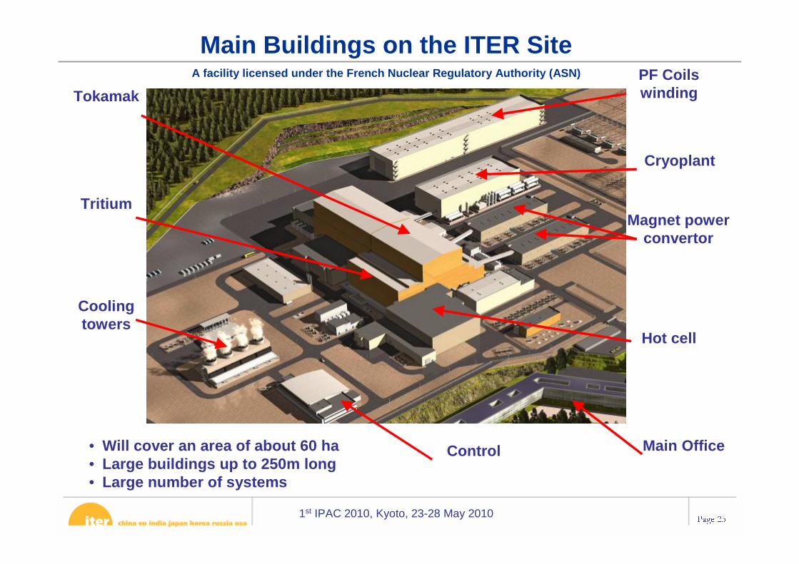
Main Buildings on the ITER SiteA facility licensed under the French Nuclear Regulatory Authority (ASN)
• Will cover an area of about 60 ha• Large buildings up to 250m long• Large number of systems
Tritium
Cryoplant
Magnet power convertor
Cooling towers
Hot cell
TokamakPF Coils winding
Main OfficeControl
1st IPAC 2010, Kyoto, 23-28 May 2010Page 26
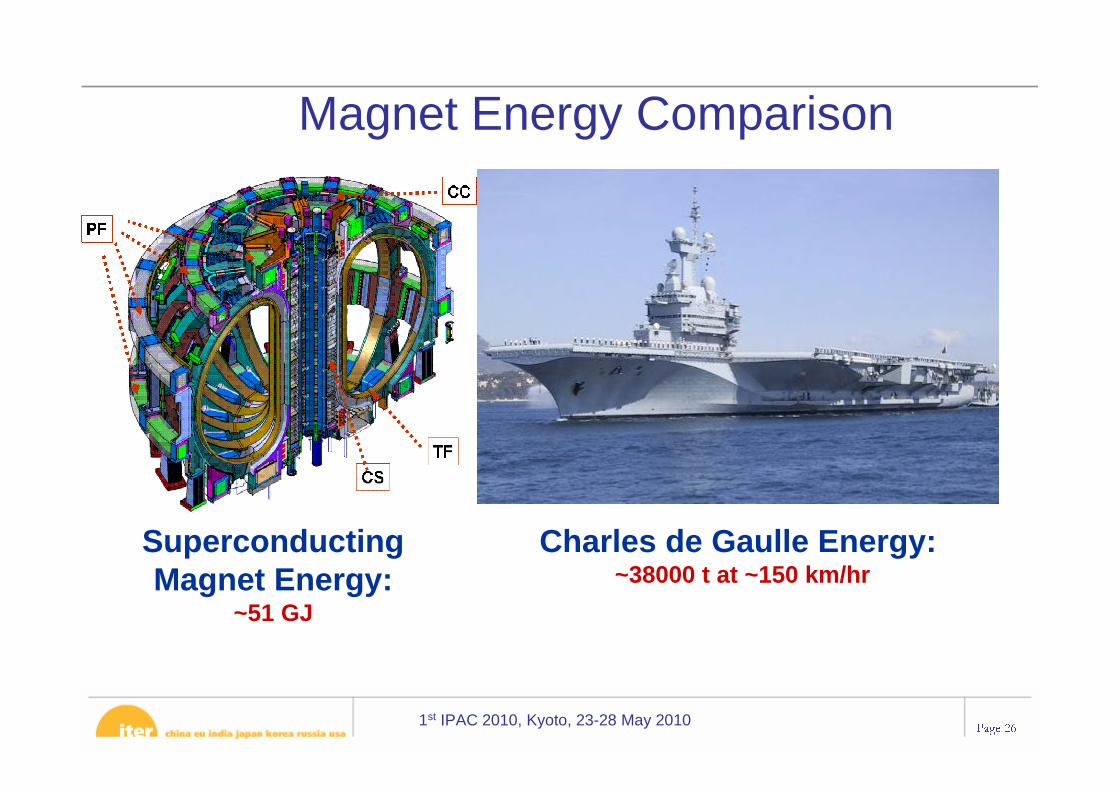
Magnet Energy Comparison
Superconducting Magnet Energy:
~51 GJ
Charles de Gaulle Energy: ~38000 t at ~150 km/hr
1st IPAC 2010, Kyoto, 23-28 May 2010Page 27
TF Coil TF Coil –– Mass ComparisonMass Comparison
Mass of (1) TF Coil: ~360 t
16 m Tall x 9 m Wide
Boeing 747-300 (Maximum Takeoff Weight)
~377 t
1st IPAC 2010, Kyoto, 23-28 May 2010Page 28
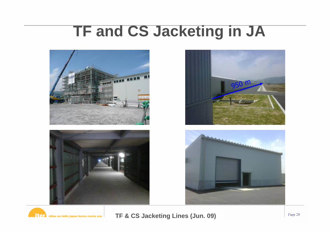
TF and CS Jacketing in JA
TF & CS Jacketing Lines (Jun. 09)
950 m
1st IPAC 2010, Kyoto, 23-28 May 2010Page 29
TF & PF Jacketing Lines at ASIPP (March−June 09)
1st IPAC 2010, Kyoto, 23-28 May 2010Page 30
Paux for Q=10 nominal scenario: 40-50MW
NBI Layout
DNB
120GHz
Heating System Stage 1 PossibleUpgrade
Remarks
NBI(1MeV Šive ion)
33 16.5 Vertically steerable(z at Rtan
-0.42m to +0.16m)
ECH&CD(170GHz)
20 20 Equatorial and upper portlaunchers steerable
ICH&CD(40-55MHz)
20 2ΩT (50% power to ionsΩHe3 (70% power to ions,
FWCD)
LHH&CD(5GHz)
20 1.8<npar<2.2
Total 73 130(110
simultan)
Upgrade in different RFcombinations possible
ECRH Startup 2
Diagnostic Beam(100keV, H-)
>2
ITER Heating and Current Drive
126 or 170GHz
1st IPAC 2010, Kyoto, 23-28 May 2010Page 31
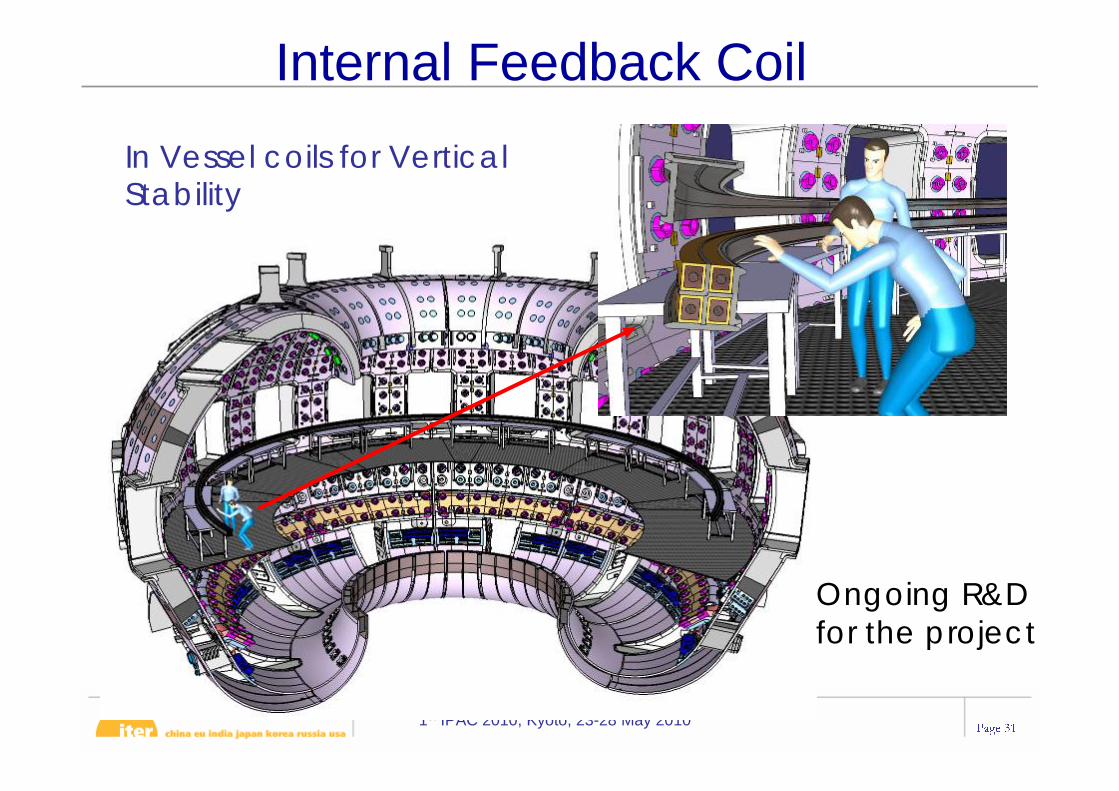
Internal Feedback Coil
In Vessel coils for Vertical Stability
Ongoing R&D for the project
1st IPAC 2010, Kyoto, 23-28 May 2010Page 32
EPAC 2006Mid-2008 End-2016
Project Status: Scope – Schedule - Cost• Following a design review that finished in 2007, the scope
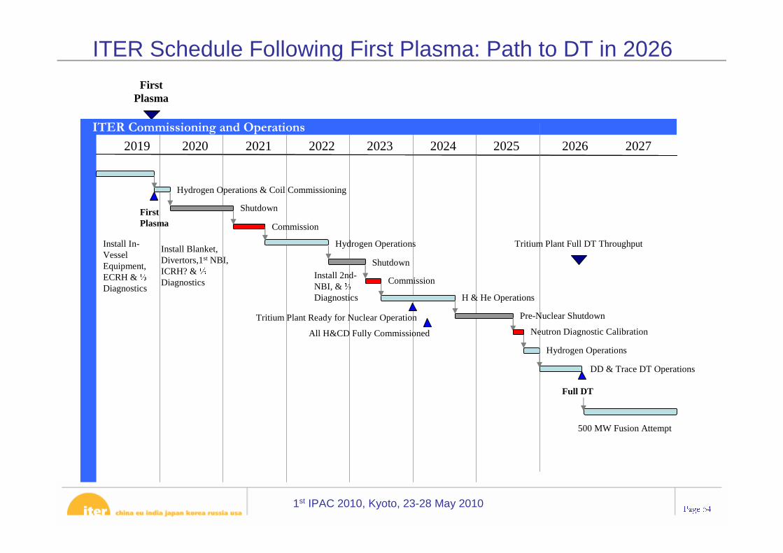
of ITER was fixed in June 2008. In parallel actual cost and an executable schedule was developed. [When this talk was given in 2006, First Plasma should happen approximately 8 years after construction begin (2016)]
• The “First Plasma” initiation is planned for Nov 2019. Deuterium - Tritium Operation for 2026. Between 2019 and 2026 a series of final construction steps and upgrades will lead to full performance operation.
• The council will [should] approve in June 2010 the baseline together with the cost increase of ITER in its next meeting.
1st IPAC 2010, Kyoto, 23-28 May 2010Page 33 1
PresentPresent ITER Construction Site ITER Construction Site
JWS 2 JWS 3
The creation and improvement of 106 kilometres of access roads from Fosharbour to Cadarache will be finished by February 2010.
Future Tokamak Complex
1st IPAC 2010, Kyoto, 23-28 May 2010Page 34
Itinerary of ITER ComponentsItinerary of ITER Components
= Itinerary of ITER Components
ITER Site
1st IPAC 2010, Kyoto, 23-28 May 2010Page 35
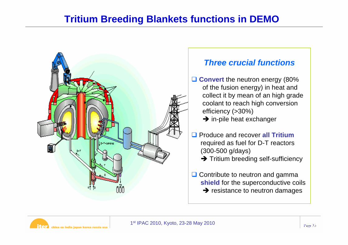
Tritium Breeding Blankets functions in DEMO
Three crucial functions
� Convert the neutron energy (80% of the fusion energy) in heat andcollect it by mean of an high gradecoolant to reach high conversionefficiency (>30%) � in-pile heat exchanger
� Produce and recover all Tritiumrequired as fuel for D-T reactors(300-500 g/days)� Tritium breeding self-sufficiency
� Contribute to neutron and gammashield for the superconductive coils � resistance to neutron damages
CS Final Design Approved CS3L CS3U CS Ready for Machine Assembly
Construction Contract Award Tokamak Bldg 11 RFE
1st IPAC 2010, Kyoto, 23-28 May 2010Page 46
• ELMs were identified as potential show stoppers in 2004
• Between 20-40 MJ of Energy per burst can hit the wall locally
• The outside magnetic field is randomly perturbed to allow constant diffusion of energy
Edge Located Mode Control/ Mitigation
RMP Coils
VS Coils
1st IPAC 2010, Kyoto, 23-28 May 2010Page 47
VV and In-Vessel Components• Key issues resolved:• Blanket loads on VV• Neutron shielding• Blanket manifold design & interface with VV• ELM coil design & interface with VV• VV manufacturability
1st IPAC 2010, Kyoto, 23-28 May 2010Page 48
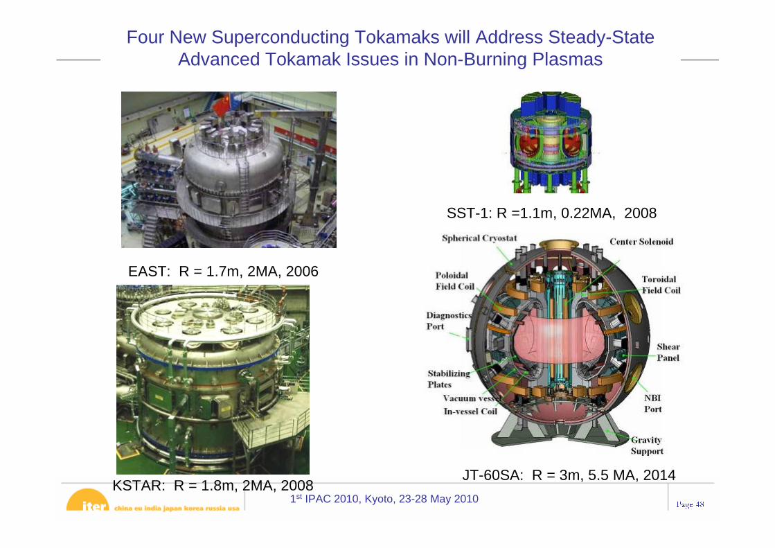
EAST: R = 1.7m, 2MA, 2006
KSTAR: R = 1.8m, 2MA, 2008
SST-1: R =1.1m, 0.22MA, 2008
JT-60SA: R = 3m, 5.5 MA, 2014
Four New Superconducting Tokamaks will Address Steady-State Advanced Tokamak Issues in Non-Burning Plasmas
1st IPAC 2010, Kyoto, 23-28 May 2010Page 49
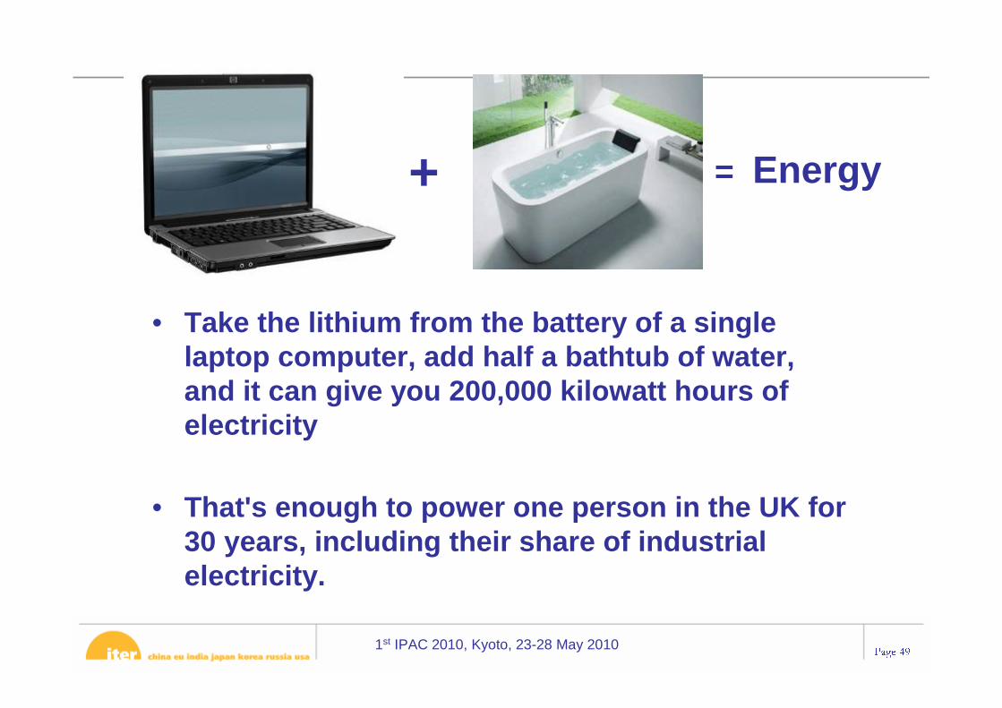
• Take the lithium from the battery of a single laptop computer, add half a bathtub of water, and it can give you 200,000 kilowatt hours of electricity
• That's enough to power one person in the UK for 30 years, including their share of industrial electricity.
+ = Energy
1st IPAC 2010, Kyoto, 23-28 May 2010Page 50
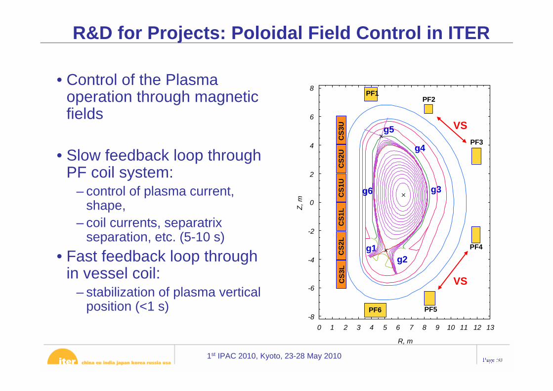
• Control of the Plasma operation through magnetic fields
• Slow feedback loop through PF coil system:
– control of plasma current, shape,
– coil currents, separatrixseparation, etc. (5-10 s)
• Fast feedback loop through in vessel coil:
– stabilization of plasma vertical position (<1 s)
R&D for Projects: Poloidal Field Control in ITER
. .
-8
-6
-4
-2
0
2
4
6
8
0 1 2 3 4 5 6 7 8 9 10 11 12 13
Z, m
R, mC
S3U
CS
2UC
S1U
CS
1LC
S2L
CS
3L
PF1PF2
PF3
PF4
PF5PF6
g1g2
g4
g3
g5
g6
VS
VS
1st IPAC 2010, Kyoto, 23-28 May 2010Page 51
• Control of the Plasma operation through magnetic fields
• Slow feedback loop through PF coil system:
– control of plasma current, shape,
– coil currents, separatrixseparation, etc. (5-10 s)
• Fast feedback loop through in vessel coil:
– stabilization of plasma vertical position (<1 s)
R&D for Projects: Poloidal Field Control in ITER
. .
-8
-6
-4
-2
0
2
4
6
8
0 1 2 3 4 5 6 7 8 9 10 11 12 13
Z, m
R, mC
S3U
CS
2UC
S1U
CS
1LC
S2L
CS
3L
PF1PF2
PF3
PF4
PF5PF6
g1g2
g4
g3
g5
g6
VS
VS
1st IPAC 2010, Kyoto, 23-28 May 2010Page 52
48 superconducting coils – 18 TF coils– 6 CS modules– 6 PF coils– 9 pairs of CC
Overview of the Magnet System
1st IPAC 2010, Kyoto, 23-28 May 2010Page 53
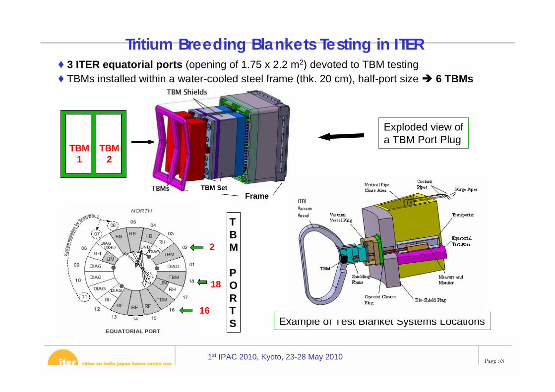
♦ 3 ITER equatorial ports (opening of 1.75 x 2.2 m2) devoted to TBM testing♦ TBMs installed within a water-cooled steel frame (thk. 20 cm), half-port size � 6 TBMs
TBM
TBM1
TBM2
TBM
PORTS
16
18
2
Exploded view of a TBM Port Plug
Example of Test Blanket Systems Locations
TBM SetFrame
Tritium Breeding Blankets Testing in ITER
1st IPAC 2010, Kyoto, 23-28 May 2010Page 54
ITER Schedule Following First Plasma: Path to DT in 2026
ITER Licensing Process• Accordance with French regulations ITER is a “basic nuclear facility” (Installation
Nucléaire de Base, INB) e.g. labs, fuel plants, not fission reactors. Compliance with international standards of safety (IAEA)
• Licensing process:– Safety options report submitted and reviewed 2002– Series of informal technical meetings with the authorities (ASN) and their technical
advisors (IRSN), 2006 – 2008.– License application documents were submitted January 2008
• Request for authorisation (Demande d’Autorisation de Création, DAC), including Impact Study
• Preliminary Safety Report (Rapport Préliminaire de Sûreté, RPrS)
• Examination of files submitted in January 2008– Authorities (ASN & IRSN) reviewed our files for acceptability– In July 2008, they requested detailed additional information in the files– DAC and RPrS are now being updated, for re-submission in 2010
• Next: Public Enquiry. Then examination by panel of independent experts (GroupePermanent) to advise ASN.
1st IPAC 2010, Kyoto, 23-28 May 2010Page 56
Current status
• All RPrS chapters and Impact Study are in first draft– Some require completion with the outcome of safety analyses in
progress, or design information from baseline documents to be fixed
• Many annexe documents completed– Translation into French under way
• Reviews of RPrS to be held October – December, by technical ROs, Safety Control Division (“second level” check), and in review including external experts - English version to be finalized by end of 2009
• Translation in French and final checking– Submission expected end of February 2010
• Should lead to issue of decree allowing “creation” of facility.– Further processes will follow to obtain authorisation for commissioning
and start-up.
1st IPAC 2010, Kyoto, 23-28 May 2010Page 57
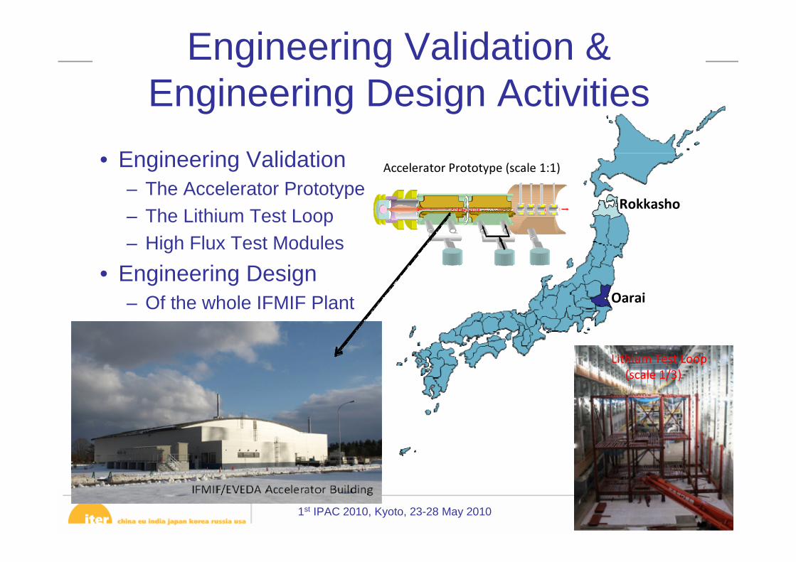
Annex IIFMIF/EVEDA
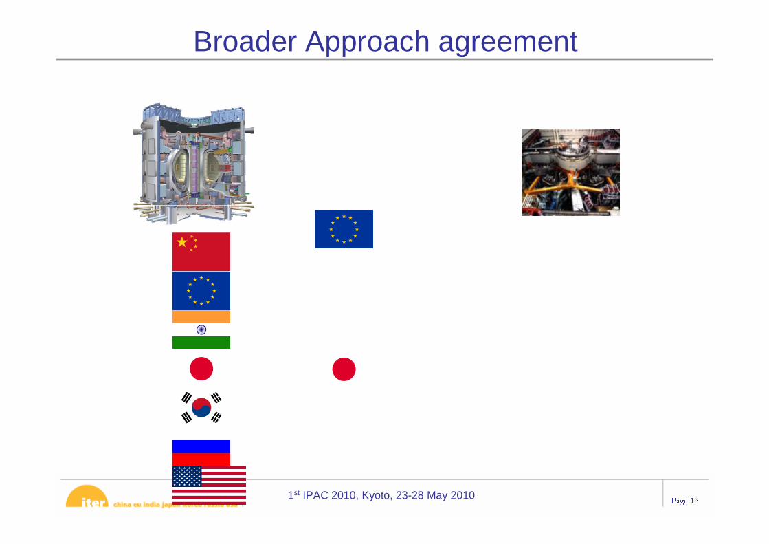
1.In accordance with this Agreement, the Parties, subject to their laws and regulations, shall conduct the Engineering Validation and Engineering Design Activities (hereinafter “EVEDA”) to produce a detailed, complete, and fully integrated engineering design of the International Fusion Materials Irradiation Facility (hereinafter “IFMIF”) and all data necessary for future decisions on the construction, operation,
Broader Approach Agreement
1st IPAC 2010, Kyoto, 23-28 May 2010Page 58
Annex IIFMIF/EVEDA
1.In accordance with this Agreement, the Parties, subject to their laws and regulations, shall conduct the Engineering Validation and Engineering Design Activities (hereinafter “EVEDA”) to produce a detailed, complete, and fully integrated engineering design of the International Fusion Materials Irradiation Facility (hereinafter “IFMIF”) and all data necessary for future decisions on the construction, operation,
Broader Approach Agreement
“Produce a detailed, complete, and fully integrated engineering design of IFMIF and all data necessary for
future decisions on the construction, operation, exploitation and decommissioning of IFMIF
“Produce a detailed, complete, and fully integrated engineering design of IFMIF and all data necessary for
future decisions on the construction, operation, exploitation and decommissioning of IFMIF
Validate continuous and stable operation of each IFMIF subsystem”
Validate continuous and stable operation of each IFMIF subsystem”
1st IPAC 2010, Kyoto, 23-28 May 2010Page 59
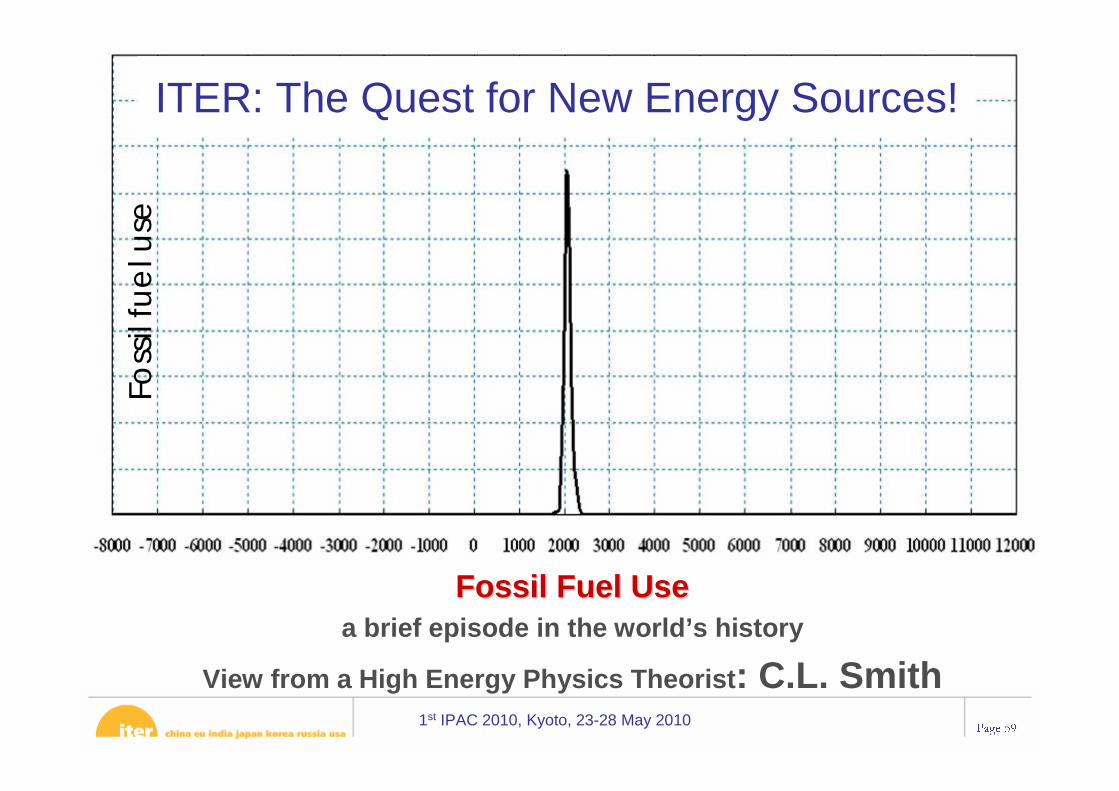
Fossil Fuel UseFossil Fuel Usea brief episode in the world’s history
View from a High Energy Physics Theorist: C.L. Smith


![Mechanics of the IFMIF RFQ cavity - INFN Padovapepato/Busetto/IFMIF_PD_12062008 [Read-Only].pdf · Mechanics of the IFMIF RFQ cavity Adriano Pepato ... • ANSYS 11.0 Multiphysics](https://static.documents.pub/doc/80x56/5acc9c547f8b9a73128d09f0/mechanics-of-the-ifmif-rfq-cavity-infn-pepatobusettoifmifpd12062008-read-onlypdfmechanics.jpg)
