International Engineering Research Journal Special Edition PGCON-MECH-2017 1 International Engineering Research Journal Eulerian-Lagrangian CFD modeling of coal gasification MadhuraThakare † and A.A.Nene ‡ † MechanicalDepartment (Heat Power Engineering), MIT, SavitribaiPhule Pune University, Pune, 411038, India. ‡ MechanicalDepartment, MIT, SavitribaiPhule Pune University, Pune, 411038, India. Abstract A computational model is applied to investigate thermal flow and gasification of coal in gasifier using commercial CFD (computational fluid dynamics) solver STAR CCM+. The Eulerian-Lagrangian approach is used to model this work. The Eulerian approach is used to model air while theLagrangian approach is used to model coal particle. The objective of this work is to implement devolatilization, char oxidation and homogeneous reaction model in themulti- phase flow. Implementation of model starts with coal moisture evaporation, devolatilization, char oxidation and lastly homogeneous reactions in themulti-phase flow. The results show that moisture evaporation, devolatilization, and char oxidation along with homogeneous reaction model are successfully implemented. Syngas composition of species at outlet mainly consist of CO, CH4, and H2. Syngas species composition is validated with experimental results. Hence, coal gasification model has been successfully implemented in thecomputational code of STAR CCM+. Keywords:Multiphase flow, Gasification simulation, coal devolatilization, char oxidation, STAR CCM+. 1. Introduction Coal is theprimary source of fossil fuel in India. Coal is cheap and readily available in India as compared to other fossil fuel. Hence, it becomes theprimary source of energy in Indian industry. But, coal has its own drawback as it is most polluting fuel. Also, the traditional method used to utilized energy from coal are low efficient and high pollutant prone. Hence, there is must do athing to developed new method to utilized large amount of energy benefits from coal without pollution. For this integrated gasification combined cycle serve our need. As compare to combustion, gasification is amuch cleaner process along with high efficient. As we know, theend product of combustion is only heating source along with polluting product gas. But, in thecase of gasification, syngas gas have heating source ability with productive species such as CO, O2, methane, etc. Gasification gives heating effect with which we can produce steam and hence electricity. Also, syngas so obtain can chemically process and synthetic fuel can be obtained. This synthetic fuel will be alternative to our conventional fossil fuel. In this century, we have ahighly efficient computer and highly advanced numerical method. The combination of this two can give us anoptimum solution to thermochemical process. Computational fluid dynamics offer aneffective mean of quantifying physical and chemical process in coal thermochemical reactor under various operating condition. The accurate results from simulation help to optimize the system design and operating condition. Also, thedynamic process can be understood clearly within the reactor. Adam Klimanek (2014) done a research work on anumerical model of coal gasification in circulating fluidized bed. The eulerian-lagrangian approach has been used. To simulate Particle flow in continuous phase has been amodel using discrete dense phase model. Homogeneous and heterogeneous reaction are amodel using eddy dissipation model and finite rate chemistry.G.k.singh (2015), work on pilot scale bubbling fluidized bed gasifier for high ash Indian coal gasification. The eulerian-eulerian approach has been used in this work. The homogenous reaction has been amodel using eddy dissipation model while user defines function has been used for theheterogeneous reaction. Jun Xie (2013), developed athree-dimensional numerical model for coal gasification in fluidized bed gasifier. The Eulerian approach used for continuous phase while Lagrangian used for discrete phase. Jobaidar Khan (2013), investigate the thermal flow and gasification in themild gasifier. The eulerian-eulerian approach is considered. For devolatilization special code has been generated and successfully implemented. Ravi Inder Singh (2013), studied the detailing of combustion and gasification process in afluidized bed. CFD modeling is used to analysis the effect of theoperating parameter. In this work, numerical analysis is done using commercial CFD solver STAR CCM+. There is no literature available on CFD analysis of coal gasification using STAR CCM+. Also, for present work Eulerian- Lagrangian approach is used to model multiphase flow. The Eulerian approach used to model gaseous phase while Lagrangian approach used solid phase. As mention above Adam klimanek (2014) used Eulerian- lagrangian approach but method used to model chemical kinetics are different. In Adam Klimanek work, user define fuction is used to model chemical kinetics while in this present work Arrhenius equation
Transcript
International Engineering Research Journal Special Edition PGCON-MECH-2017
1
International Engineering Research Journal Eulerian-Lagrangian CFD modeling of coal gasification
MadhuraThakare† and A.A.Nene‡
†MechanicalDepartment (Heat Power Engineering), MIT, SavitribaiPhule Pune University, Pune, 411038, India. ‡MechanicalDepartment, MIT, SavitribaiPhule Pune University, Pune, 411038, India.
Abstract A computational model is applied to investigate thermal flow and gasification of coal in gasifier using commercial CFD (computational fluid dynamics) solver STAR CCM+. The Eulerian-Lagrangian approach is used to model this work. The Eulerian approach is used to model air while theLagrangian approach is used to model coal particle. The objective of this work is to implement devolatilization, char oxidation and homogeneous reaction model in themulti-phase flow. Implementation of model starts with coal moisture evaporation, devolatilization, char oxidation and lastly homogeneous reactions in themulti-phase flow. The results show that moisture evaporation, devolatilization, and char oxidation along with homogeneous reaction model are successfully implemented. Syngas composition of species at outlet mainly consist of CO, CH4, and H2. Syngas species composition is validated with experimental results. Hence, coal gasification model has been successfully implemented in thecomputational code of STAR CCM+. Keywords:Multiphase flow, Gasification simulation, coal devolatilization, char oxidation, STAR CCM+. 1. Introduction Coal is theprimary source of fossil fuel in India. Coal is cheap and readily available in India as compared to other fossil fuel. Hence, it becomes theprimary source of energy in Indian industry. But, coal has its own drawback as it is most polluting fuel. Also, the traditional method used to utilized energy from coal are low efficient and high pollutant prone. Hence, there is must do athing to developed new method to utilized large amount of energy benefits from coal without pollution. For this integrated gasification combined cycle serve our need. As compare to combustion, gasification is amuch cleaner process along with high efficient. As we know, theend product of combustion is only heating source along with polluting product gas. But, in thecase of gasification, syngas gas have heating source ability with productive species such as CO, O2, methane, etc. Gasification gives heating effect with which we can produce steam and hence electricity. Also, syngas so obtain can chemically process and synthetic fuel can be obtained. This synthetic fuel will be alternative to our conventional fossil fuel. In this century, we have ahighly efficient computer and highly advanced numerical method. The combination of this two can give us anoptimum solution to thermochemical process. Computational fluid dynamics offer aneffective mean of quantifying physical and chemical process in coal thermochemical reactor under various operating condition. The accurate results from simulation help to optimize the system design and operating condition. Also, thedynamic process can be understood clearly within the reactor. Adam Klimanek (2014) done a research work on anumerical model of coal gasification in circulating
fluidized bed. The eulerian-lagrangian approach has been used. To simulate Particle flow in continuous phase has been amodel using discrete dense phase model. Homogeneous and heterogeneous reaction are amodel using eddy dissipation model and finite rate chemistry.G.k.singh (2015), work on pilot scale bubbling fluidized bed gasifier for high ash Indian coal gasification. The eulerian-eulerian approach has been used in this work. The homogenous reaction has been amodel using eddy dissipation model while user defines function has been used for theheterogeneous reaction. Jun Xie (2013), developed athree-dimensional numerical model for coal gasification in fluidized bed gasifier. The Eulerian approach used for continuous phase while Lagrangian used for discrete phase. Jobaidar Khan (2013), investigate the thermal flow and gasification in themild gasifier. The eulerian-eulerian approach is considered. For devolatilization special code has been generated and successfully implemented. Ravi Inder Singh (2013), studied the detailing of combustion and gasification process in afluidized bed. CFD modeling is used to analysis the effect of theoperating parameter. In this work, numerical analysis is done using commercial CFD solver STAR CCM+. There is no literature available on CFD analysis of coal gasification using STAR CCM+. Also, for present work Eulerian-Lagrangian approach is used to model multiphase flow. The Eulerian approach used to model gaseous phase while Lagrangian approach used solid phase. As mention above Adam klimanek (2014) used Eulerian-lagrangian approach but method used to model chemical kinetics are different. In Adam Klimanek work, user define fuction is used to model chemical kinetics while in this present work Arrhenius equation
International Engineering Research Journal Special Edition PGCON-MECH-2017
2
is used to model chemical kineticsfor both hetereogeneous and homogeneous reaction. 2. Gasification Theory 2.1.Gasification and Combustion Gasification and combustion these both processes are used to convert solid fuel into productive gases along with heat energy. But, this process occurs at thedifferent environmental condition. Combustion is done in oxygen enriched environment while gasification required alimited amount of oxygen. Combustion is nothing but burning of fuel in boiler, stove, and furnace to generate heat. This heat is then used to produce steam and indirectly electricity through steam turbines. At the end of combustion, we got CO2 and H2O as product gas. These product gas can only be used as aheating source. Also, these are polluting gases. Gasification is nothing but the partial combustion of fuel. Gasification is done in alimited oxygen environment. Syngas mainly includes CO, H2,
methane and other species. This syngas has multiple application instead of just using as aheating source. Like it can be used produce methane, methanol, hydrogen and much more. Also, after few chemical process, this syngas can be converted into synthetic fuel which can serve as analternative to fossil fuel. 2.2. Gasification The thermochemical conversion of fuel in product gas which contains mainly CO, H2 and methane is called as gasification. For gasification, alimited amount of oxygen, air or air with steam can be used as gasifying agents. Gasification is mainly done through following four stage which is drying, devolatilization, oxidation, and reduction. 2.2.1. Drying Solid fuel always contains some amount of moisture. For efficient gasification fuel should be completely dry. Hence, in thefirst stage of gasification drying of solid is done. The temperature at this stage is about 100-200°C which helps to remove moisture from fuel and formvapor of it. There will be no further decomposition of fuel as thetemperature is pretty low to decompose fuel. 2.2.2. Devolatilization Devolatilization is theremoval of volatile matter from solid fuel. Mostly, this process occurs at atemperature ranging from 200-300°C. In thecase of coal as solid fuel, coal consist of char, volatile matter, moisture and ash. In trying process moisture are removed hence, there will be char, volatile matter and ash only. During devolatilization, volatile matter from coal is taken out. As there is theremoval of volatile matter, there will be areduction in weight. Devolatilization is mostly depended upon characteristics and type of coal. This
reaction is endothermic hence, to complete this reaction we need to add heat into it. 2.2.3. Char Oxidation After devolatilization, remaining productsis char and ash where thereactive product is only charred as Ash is sort of inert material. In oxidation stage, O2, CO2, and H2O react with char. This reaction is exothermic which release the heat and supply heat to other endothermic reaction. 2.2.4. Reduction This stage includes reduction reaction in absence of oxygen. These are anendothermic reaction. After all stage, product gas that is syngas mostly contain CO, CO2, CH4, and H2.
3. Numerical analysis: 3.1. Geometry and material Geometry used in this work is shown in figure1. The total height of gasifier is 4m having three opening. Two inlets for agasifying agent and another for coal along with this there will be one outlet for syngas. The diameter for air inlet is 250 mm located at the bottom of gasifier as shown in Figure1. The coal inlet has adiameter of 80mm located at 500mm height and to the left side of thegasifier. An outlet for syngas is given at top of gasifier having 350mm of diameter. The material used is Indonesian coal having adensity of 1200 kg/m3. The diameter of coal is 10µm. the proximate and ultimate analysis is given in Table 1 and Table 2 respectively.
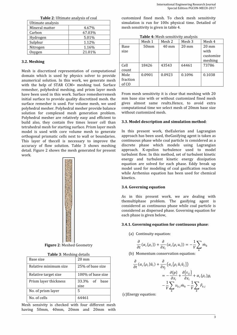
3.2. Meshing Mesh is discretized representation of computational domain which is used by physics solver to provide anumerical solution. In this work, we generate mesh with the help of STAR CCM+ meshing tool. Surface remesher, polyhedral meshing, and prism layer mesh have been used in this work. Surface remesherremesh initial surface to provide quality discretized mesh. the surface remesher is used. For volume mesh, we used polyhedral mesher. Polyhedral mesher provide balance solution for complexed mesh generation problem. Polyhedral mesher are relatively easy and efficient to build also, they contain five times lesser cell than tetrahedral mesh for starting surface. Prism layer mesh model is used with core volume mesh to generate orthogonal prismatic cells next to wall or boundaries. This layer of thecell is necessary to improve the accuracy of flow solution. Table 3 shows meshing detail. Figure 2 shows the mesh generated for present work.
Figure 2: Meshed Geometry
Table 3: Meshing details
Base size 20 mm
Relative minimum size 25% of base size
Relative target size 100% of base size
Prism layer thickness 33.3% of base size
No. of prism layer 5
No. of cells 64461
Mesh sensivity is checked with four different mesh having 50mm, 40mm, 20mm and 20mm with
customized fined mesh. To check mesh sensitivity simulation is run for 100s physical time. Detailed of mesh sensitivity is given in table 4.
From mesh sensitivity it is clear that meshing with 20 mm base size with or without customized fined mesh gives almost same reults.Hence, to avoid extra computational time we select mesh of 20mm base size without customized mesh. 3.3. Model description and simulation method: In this present work, theEulerian and Lagrangian approach has been used, theGasifying agent is taken as continuous phase while coal particle is considered as a discrete phase which models using Lagrangian approach. K-epsilon turbulence used to model turbulent flow. In this method, set of turbulent kinetic energy and turbulent kinetic energy dissipation equation are solved for each phase. Eddy break up model used for modeling of coal gasification reaction while Arrhenius equation has been used for chemical kinetics. 3.4. Governing equation As in this present work, we are dealing with themultiphase problem. The gasifying agent is considered as continuous phase while coal particle is considered as dispersed phase. Governing equation for each phase is given below, 3.4.1. Governing equation for continuous phase:
(a) Continuity equation:
𝜕
𝜕𝑡 𝛼𝑐 𝜌𝑐 +
𝜕
𝜕𝑥𝑖
𝛼𝑐 𝜌𝑐𝑢𝑖 = −1
𝑉 𝑚 𝑘𝑘
(b) Momentum conservation equation:
𝜕
𝜕𝑡 𝛼𝑐 𝜌𝑐 𝑢 𝑖 +
𝜕
𝜕𝑥𝑗
𝛼𝑐 𝜌𝑐𝑢 𝑖𝑢 𝑗
= −𝜕 𝑝
𝜕𝑥𝑖
+𝜕 𝜏𝑖𝑗
𝜕𝑥𝑖
+ 𝛼𝑐{𝜌𝑐}𝑔𝑖
−1
𝑉 𝑣𝑘 ,𝑖𝑚 𝑘𝑘
−1
𝑉 𝐹 𝑘 ,𝑖
𝑘
(c)Energy equation:
International Engineering Research Journal Special Edition PGCON-MECH-2017
4
𝜕
𝜕𝑡 𝛼𝑐 𝜌𝑐 𝑖 𝑖 +
𝜕
𝜕𝑥𝑖
𝛼𝑐 𝜌𝑐𝑢𝑖𝑖𝑐
=𝜕
𝜕𝑥𝑖
𝑘𝑒𝑓𝑓
𝜕 𝑇𝐶
𝜕𝑥𝑖
+ 𝛼𝑐{∅}
−1
𝑉 𝑣𝑘 ,𝑖𝑚 𝑘𝑘
− 𝑞 𝑘𝑘
3.4.2. Governing equation for dispersed phase: (a)Particle motion:
𝑑𝑣
𝑑𝑡=
𝐹𝑓
𝑚+ 𝑔
(b)The trajectory of particle: 𝑑𝑥𝑝
𝑑𝑡= 𝑣
(c)The temperature of particle: 𝑑𝑇𝑑
𝑑𝑡=
1
𝑚𝑐𝑑
(𝑄 𝑑 + 𝑚 𝐿)
3.4.3. Turbulence model: (a)Equation for turbulent kinetic energy: 𝜕
𝜕𝑡 𝜌𝑘 +
𝜕
𝜕𝑥𝑖
𝜌𝑣𝑗𝑘 =𝜕
𝜕𝑥𝑗
𝜇 +𝜇𝑡
𝜎𝑘
𝜕𝑘
𝜕𝑥𝑗
+ 𝐺𝑘 + 𝐺𝑏 − 𝜌𝜀
(b)The equation for Turbulent dissipation rate: 𝜕
𝜕𝑡 𝜌𝜀 +
𝜕
𝜕𝑥𝑖
𝜌𝑣𝑗 𝜀
=𝜕
𝜕𝑥𝑗
𝜇 +𝜇𝑡
𝜎𝜖
𝜕𝜖
𝜕𝑥𝑗
+ 𝐺𝑘 + 1 − 𝐴3𝜀 𝐺𝑏
+ 𝐴1𝜀
𝜀
𝑘− 𝐴2𝜀𝜌
𝜀2
𝑘
3.4.4. Species Transport equation:
𝜕(𝜌𝑌𝑘)
𝜕𝑡+
𝜕(𝜌𝑢𝑗𝑌𝑘)
𝜕𝑥𝑗
= −𝜕
𝜕𝑥𝑗
𝜌𝐷𝑘
𝜕𝑌𝑘
𝜕𝑥𝑗
+ 𝜔𝑘
3.5. Chemical kinetics: 3.5.1. Coal moisture evaporation: The moisture contains coal particle is assumed to coat the particle moisture evaporation occur rapidly before the mass transfer process takes place. The continuity equation for moisture component in particle p given as
𝑑𝛼𝑤𝑝 𝑚𝑝
𝑑𝑡= − 𝑟𝑤𝑝
3.5.2. Raw coal devolatilization: Devolatilization is a step where thevolatile matter gets out of coal particle.
𝑅𝑎𝑤𝑐𝑜𝑎𝑙 → 𝑌𝑌𝑝𝑛 𝑣𝑜𝑙𝑎𝑡𝑖𝑙𝑒 𝑚𝑎𝑡𝑡𝑒𝑟
+ 1 − 𝑌𝑌𝑝𝑛 𝑐𝑎𝑟
The continuity equation for raw coal component in particle p is given as
𝑑𝛼𝑐𝑝
𝑑𝑡= −𝑟𝑐𝑝
The net rate of raw coal consumption given as
𝑟𝑐𝑝 = 𝑘𝑝𝑛𝛼𝑐𝑝
Kpn is reaction rate constant calculate using
𝑘𝑝𝑛 = 𝐴𝑝𝑛 𝑒𝑥𝑝 −𝐸𝑝𝑛
𝑅𝑢𝑇𝑝
3.5.3. First order char oxidation: Char remain after devolatilization react with O2, H2O, and CO2 in the following form,
𝑐𝑎𝑟 + 𝑜𝑥𝑑𝑖𝑧𝑒𝑟 → (𝑝𝑟𝑜𝑑𝑢𝑐𝑡) The continuity equation for char component in particle p.
𝑑𝑚𝑝
𝑑𝑡= − 𝑟𝑝
The rate of formation of char from particle p,
𝑟𝑝 = 𝑟𝑣𝑝 (1 − 𝑌𝑌𝑝𝑛 )/𝑌𝑌𝑝𝑛
The rate of reaction is calculated as follows,
𝑘𝑝𝑙 = 𝐴𝑝𝑙𝑇𝑝𝑛𝑒𝑥𝑝 −
𝐸𝑝𝑙
𝑅𝑢𝑇𝑝
The devolatilization and char oxidation reaction with their properties are given in Table 4 and 5 respectively.
Table 5: Properties of Two step devolatilization
Properties First step devolatilization
Second step devolatilization
Activation energy
(kJ/kmol)
7.36×10⁴ 2.51×10⁵
Pre-exponential
factor
3.7×10⁵ 1.5×10¹³
YY 0.4 0.8 Char oxidation reaction: Reaction 1:
2𝑐𝑎𝑟 + 𝑂2 → 2𝐶𝑂 …………...… [R1] Reaction 2:
𝑐𝑎𝑟 + 𝐻2𝑂 → 𝐶𝑂 + 𝐻2….. [R2] Reaction 3:
𝑐𝑎𝑟 + 𝐶𝑂2 → 2𝐶𝑂…………... [R3]
Table 6: Properties of Char Oxidation reaction Reaction Activation
3.6. Boundary condition: Geometry and meshing for this work have been generated in STAR CCM+ modeling and mesh. Coal and theair inlet are provided with wall and velocity inlet. Syngas outlet is given as pressure outlet. For aparticle, theinjector has been used. Surface type injector is used in this case and coal inlet surface is taken as input for theinjector. Initial and boundary condition are alist out in Table 7 and Table 8 respectively.
Table 8: Initial condition
Initial condition
Pressure 0.2bar
Species fraction N2 = 0.79 O2 = 0.21
Velocity 0.277m/s
Table 9: Boundary condition
Boundary condition (1) Air inlet
Type of boundary Velocity inlet Velocity 0.277m/s Species fraction O2 =0.21
N2 =0.79 Static temperature 850°C
(2) Coal injector Type of injector Surface injector Mass flow rate 0.0111kg/s Particle diameter 10µm Particle temperature 25°C Species fraction Rawcoal=0.8081
Ash =0.0396 Moisture=0.1523
velocity 0.001804m/s (3) Pressure outlet
Type of boundary Pressure outlet Pressure 1 atm Species fraction O2 =0.21
N2 =0.79 Static temperature 25°C
4. Results and discussion: Devolatilization and char oxidation of coal particle along with homogenous reaction has been carried out
in this work. This reaction releases coal volatile and other species. The mole fraction of CO, CH4, H2,N2,and temperature is analyzed in this work. Results from numerical analysis are validated by experimental results. 4.1. Syngas species distribution: Char oxidation reaction [R1-3] are heterogeneous reaction occurs between char and anoxidizing agent as O2, H2O, and CO2. After production of gaseous species from theheterogeneousreaction, there will be ahomogenous reaction [R4-8] to from CO, CH4, and H2. Figure 3 and 4 shows thecontour of different syngas species. Figure 5 shows, distribution of species along the axis of thegasifier. It is evident that at the bottom of gasifier concentration of CO,H2 and CH4 are lower while N2 is higher. As we move upward along the axis, theconcentration of CO, H2, and CH4 shows increasing nature while N2 shows decreasing one. At thebottom region of thegasifier, there is thepresence of char and H2O because of devolatilization reaction. Hence, theconcentration of CO, H2, and CH4 are lower in thebottom region. As moved upward, char from devolatilization get oxidized and product so formed react homogeneously to give CO, H2, and CH4. Because of this reactions, there will be anincrease in theconcentration of CO, H2, and CH4 in theupward region of thegasifier.
Figure 3: (a) Mole Fraction of CO
(b)Mole Fraction of CH4
Figure 3(a-b) and 4(c) show thedistribution of CO, H2, and CH4. While Figure 5 shows the concentration of these species along the axis of the gasifier. From the bottom of the gasifier, air is coming which have O2 and N2 as its constituent. Hence, at a bottom concentration of N2 is higher and as move upward most of the N2 combine with another unburnt hydrocarbon to form mineral matter or tar. Because of this N2 concentration shows decreasing behavior along the axis of the gasifier. Figure 4(d) and 5 shows the N2 distribution in the gasifier.
International Engineering Research Journal Special Edition PGCON-MECH-2017
6
Figure 4: (c) Mole fraction of H2 (d) Mole fraction of N2
Figure 5: Mole Fraction of species along height
4.2. Progressive generation of CH4: Progressive generation of CH4 is shown in Figure 6(a-b). The initial stage of CH4 generation is shown in figure 6(a). During theinitialstage, devolatilization occurs which release a large amount of volatile matter. This volatile matter breaks down into CH4 and CO hence, there will be ahigher concentration of CH4 during initial stage [R4]. As gasification proceed, formed CH4get to react with H2O to form CO and H2 [R8]. Hence, in thefinalstage, theCH4 concentration decreases. From figure 6(a-b)we can summarize asCH4
concentration increased in initial stage while it goes on decreasing in thefinal stage. 4.3. Progressive generation of CO: Progressive generation of CO is shown in Figure 7(a-b). In gasification, there is thecontinuous formation of CO from heterogeneous [R1-3] and homogeneous reaction [R4, R8].During theinitialstage, there is char oxidation [R1-3] which mostly gives CO hence there is increasing in concentration in this stage. As gasification proceed, thehomogeneous reaction takes place [R4, R8] and CO is generated. Hence, there is acontinuous increase of CO concentration because of heterogeneous [R1-3] and homogeneous [R4, R8] reaction which is shown in Figure 7(a-b).
Figure 6(a): Progressive generation of CH4
Figure 6(b): Progressive generation of CH4
Figure 7(a): Progressive generation of CO
4.4. Progressive generation of H2: Progressive generation of H2 is shown in Figure 8(a-b). Char oxidation [R2] and homogenous reaction [R6, R8] gives out H2. This will result in higher concentration of H2 during the initial stage of gasification which is shown in Figure 8(a). As gasification proceed, formed H2 react with oxygen to give water [R7]. Hence, there will be consumption of H2 which leads to decrease in concentration of H2 which is shown in Figure 8(b), Fromthis, we can summarizeas during gasification concentration of H2 initially increases then decreases.
International Engineering Research Journal Special Edition PGCON-MECH-2017
7
Figure 7(b): progressive generation of CO
Figure 8(a): Progressive generation of H2
Figure 8(b): Progressive generation of H2
4.5. Temperature distribution: The gasifier is initialized with 25°C but as reaction progress, hot air react with coal particle and theexothermic reaction takes place. Because of this reaction, there is acontinuous increase of temperature. After devolatilization, there will be heterogeneous [R1-3] and homogeneous [R4-8] reaction which are endothermic in nature. Hence there will be decreasing in temperature after devolatilization.The temperature
distribution along the axis of thegasifier is shown in Figure 9.The contour of temperature profile is shown in Figure 10. Temperature is ahigh in lower region where coal and air come in contact. Because there is a large amount of unreacted coal and oxygen are available which initialized the devolatilization reaction which is highly exothermic. Hence, there is theelevation of temperature in thelower region of thegasifier. As we move upward along axis there will be theoccurrence of endothermic reaction which lowers down the temperature in thegasifier. Figure 9 shows thatbetween the heights of 0.5 to 1.5 m there is increasing temperature. This is a region where theexothermic reaction occurs. While. Above 1.5m height, there is adecrease in temperature because of anendothermic reaction.
Figure 9: Temperature distribution along height
Figure 10: Temperature distribution
5. Experimental validation: Numerical results obtained from this present work are validated with experimental results of coal gasification in fluidized bed gasifier. Coal used is Indonesian coal as mention in section 3.1. The results from numerical analysis and experiment are shown in Table 9 and Figure11 shows bar chart between experimental and numerical results. Numerical results show good agreement with experimental results.
Table 10: Mole fraction of gaseous species Numerical
results Experimental
results
International Engineering Research Journal Special Edition PGCON-MECH-2017
8
Mole Fraction
CO 0.1904 0.20
CH4 0.0089 0.01
H2 0.0764 0.1
N2 0.3719 0.40
Temperature 937.67°C 950°C
Figure 11: Experimental and numerical results
6. Conclusion: The results are summarized as follows,
1. Devolatilization, char oxidation of coal particle
and thehomogenous reaction has been
successfully implemented in thecomputational
code of STAR CCM+.
2. The syngas composition i.e. CO, CH4,and H2 are
validated with experimental results and show
good behavior with theexperimental value.
3. As devolatilization is ahighly exothermic
reaction. Hence, initially temperature is high
but after theendothermicreaction, there is
adecrease in temperature.
4. For future scope, effect of coal particle size,
mass flow rate of air and mass flow rate of coal
on syngas composition has to be investigate
Nomenclature: Latin letter m = Mass v = Velocity g = Gravity t = Time x = Position c = Specific heat h = Enthalpy F = Force V = Volume T = Temperature Q = Heat transfer E = Energy of activation A = Pre-exponential factor
R = Universal gas constant r = Rate of reaction k = Rate constant YY = Mass stoichiometric coefficient Greek letter α = Volume fraction ρ = Density τ = Shear stress Sub-script K = Number of particle c = Continuous phase d = Dispersed phase p = Particle h = Char component w = Moisture component C = Raw coal component n = Devolatilization step References Adam klimanek et al, (2014), towards a hybrid Eulerian- Lagrangian CFD modeling of coal gasification in a circulating fluidized bed reactor, Fuel 2014.10.058. Jun Xie et al, (2013),aEulerian-Lagrangian method for three-dimensional simulation of fluidized bed coal gasification, Advance powder technology 24 (2013), 382-392. JianXu et al, (2012), Mathematical modeling of coal gasification process in a well-stirred reactor: effect of devolatilization and moisture content, Energy fuel, 26, 5759-5768. JobaidurKhan et al, (2013), Implementation of a demoisturization model in themulti-phase simulation of hybrid entrained flow and fluidized bed mild gasifier, clean coal and energy, 2, 35-53. G.k.singh et al, (2015), modeling and simulation of pilot scale bubbling fluidized bed gasifier for the gasification of high ash Indian coal using Eulerian granular approach, ice, 0057. A.Gomez-barea et al, (2010), modeling of biomass gasification in afluidized bed,Progress in Energy and Combustion Science 36 444–509. Ravi Inder Singh et al, (2013), CFD modeling to study fluidized bed combustion and gasification,Applied Thermal Engineering, 52-585-614. Tamer M. Ismail et al, (2016), Eulerian – Eulerian CFD model on fluidized bed gasifier using coffeehusks as fuel,Applied Thermal Engineering 106 (2016) 1391–1402.
International Engineering Research Journal Special Edition PGCON-MECH-2017
9
Zhongyi Deng et al, (2008), Computational Fluid Dynamics Modeling of Coal Gasification in aPressurized Spout-Fluid Bed,Energy & Fuels, 22, 1560–1569. G.-S. Liua et al, (2000), modeling of a pressurized entrained flow coal gasifier: the effect ofreaction kinetics and char structure,Fuel 79, 1767–1779. XiaofangWang et al, (2009), Three-dimensional simulation of fluidized bed coal gasification, Chemical Engineering and Processing 48, 695–705.