All rights reserved. Unless otherwise specified, no part of this publication may be reproduced or utilized in any form or by any means, electronic or mechanical, including photocopying and microfilm, without permission in writing from either ISO at the address below or ISO's member body in the country of the requester. / Droits de reproduction réservés. Sauf prescription différente, aucune partie de cette publication ne peut être reproduite ni utilisée sous quelque forme que ce soit et par aucun procédé, électronique ou mécanique, y compris la photocopie et les microfilms, sans l'accord écrit de l’ISO à l’adresse ci-après ou du comité membre de l’ISO dans le pays du demandeur.
ISO copyright office Case postale 56 CH-1211 Geneva 20 Tel. + 41 22 749 01 11 Fax + 41 22 749 09 47 E-mail [email protected] Web www.iso.org
Foreword ........................................................................................................................................................... vii
Introduction ........................................................................................................................................................ ix
3 Terms and definitions ........................................................................................................................... 3
4 Identification statement (Reference to this part of ISO 1219) .............................................................. 3
5 General rules .......................................................................................................................................... 3
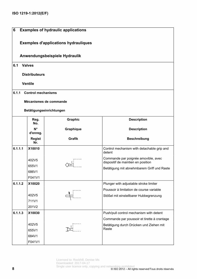
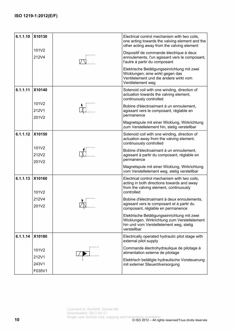
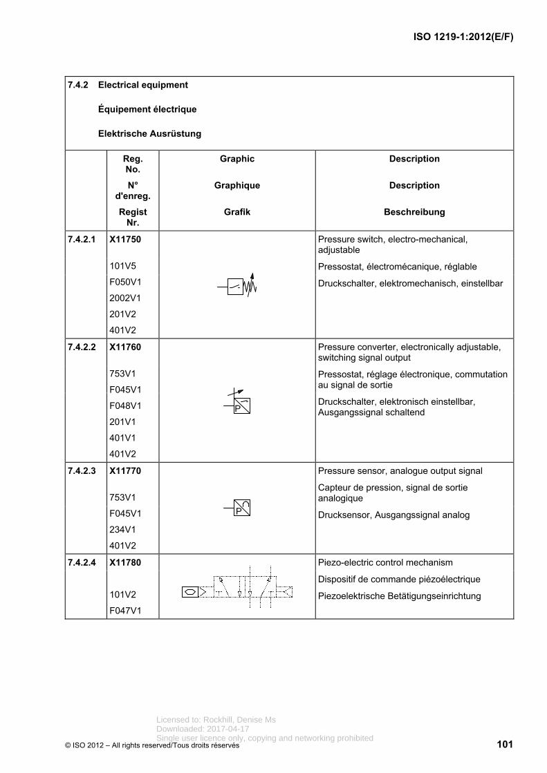
6 Examples of hydraulic applications .................................................................................................... 8 6.1 Valves ..................................................................................................................................................... 8 6.1.1 Control mechanisms ............................................................................................................................. 8 6.1.2 Directional control valves ................................................................................................................... 11 6.1.3 Pressure control valves ...................................................................................................................... 17 6.1.4 Flow-control valves ............................................................................................................................. 21 6.1.5 Non-return (check) valves and shuttle valves .................................................................................. 23 6.1.6 Proportional directional control valves ............................................................................................. 25 6.1.7 Proportional pressure control valves ................................................................................................ 29 6.1.8 Proportional flow control valves ........................................................................................................ 32 6.1.9 Two-port slip-in cartridge valves ....................................................................................................... 34 6.2 Pumps and motors .............................................................................................................................. 47 6.3 Cylinders .............................................................................................................................................. 54 6.4 Accessories ......................................................................................................................................... 57 6.4.1 Connections and joints ....................................................................................................................... 57 6.4.2 Electrical equipment ........................................................................................................................... 59 6.4.3 Measuring instruments and indicators ............................................................................................. 60 6.4.4 Filters and separators ......................................................................................................................... 64 6.4.5 Heat exchangers .................................................................................................................................. 68 6.4.6 Energy accumulators (pressure vessels, gas bottles) .................................................................... 69 6.4.7 Lubrication points ............................................................................................................................... 70
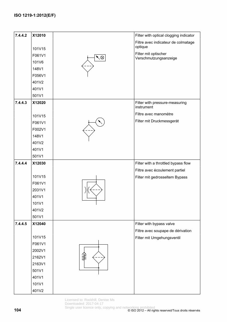
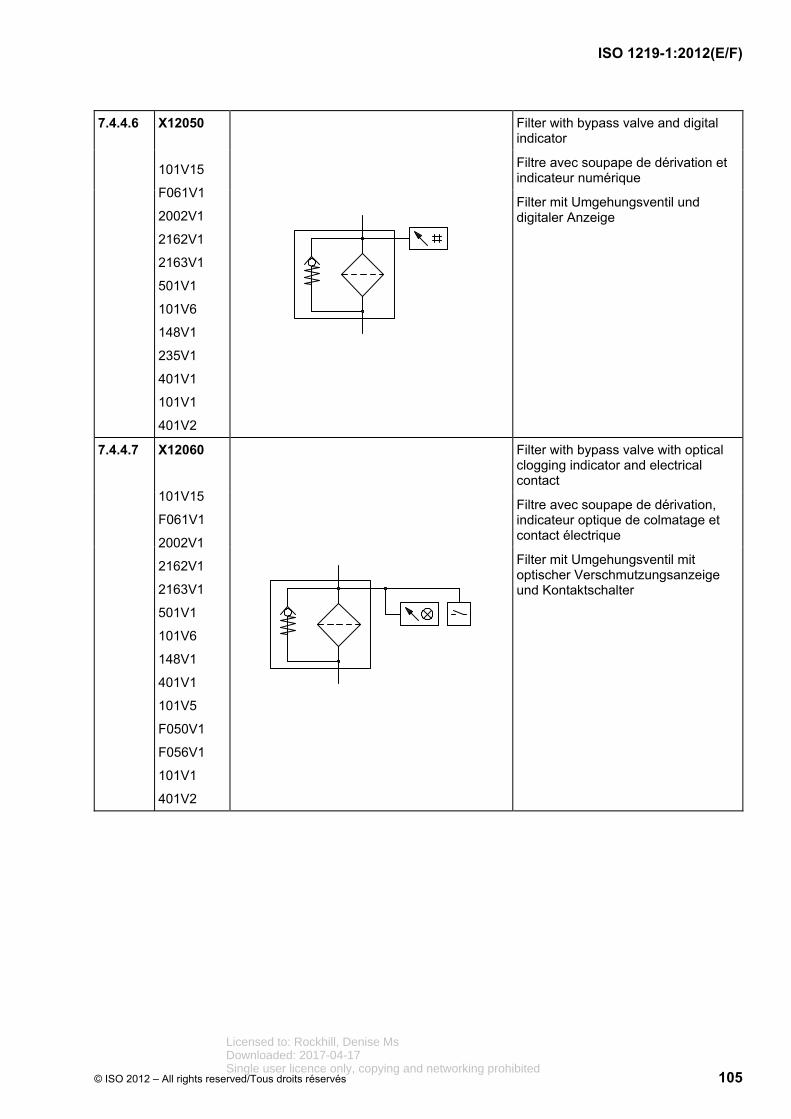
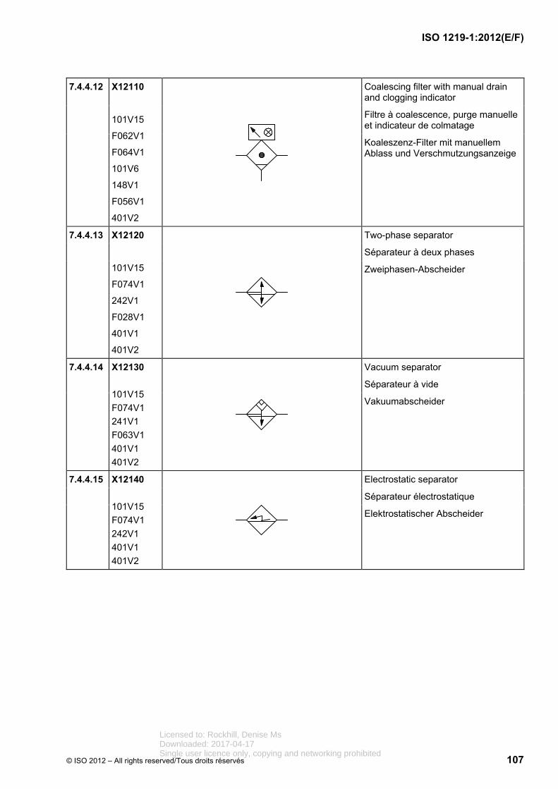
7 Examples of pneumatic applications ................................................................................................ 71 7.1 Valves ................................................................................................................................................... 71 7.1.1 Control mechanisms ........................................................................................................................... 71 7.1.2 Directional control valves ................................................................................................................... 75 7.1.3 Pressure control valves ...................................................................................................................... 84 7.1.4 Flow control valves ............................................................................................................................. 86 7.1.5 Non-return (check) valves and shuttle valves .................................................................................. 87 7.1.6 Proportional directional control valves ............................................................................................. 89 7.1.7 Proportional pressure control valves ................................................................................................ 90 7.1.8 Proportional flow control valves ........................................................................................................ 92 7.2 Air compressors and motors ............................................................................................................. 93 7.3 Cylinders .............................................................................................................................................. 94 7.4 Accessories ......................................................................................................................................... 99 7.4.1 Connections and joints ....................................................................................................................... 99 7.4.2 Electrical equipment ......................................................................................................................... 101 7.4.3 Measuring instruments and indicators ........................................................................................... 102 7.4.4 Filters and separators ....................................................................................................................... 103 7.4.5 Energy accumulators (pressure vessels, gas bottles) .................................................................. 110 7.4.6 Vacuum generators ........................................................................................................................... 111 7.4.7 Suction cups ...................................................................................................................................... 112
Licensed to: Rockhill, Denise MsDownloaded: 2017-04-17Single user licence only, copying and networking prohibited
Avant-propos ................................................................................................................................................... viii
Introduction ......................................................................................................................................................... x
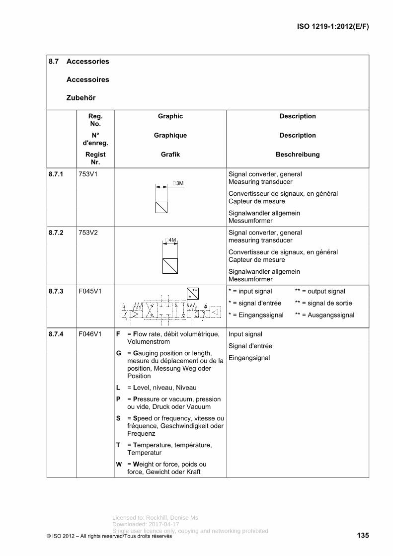
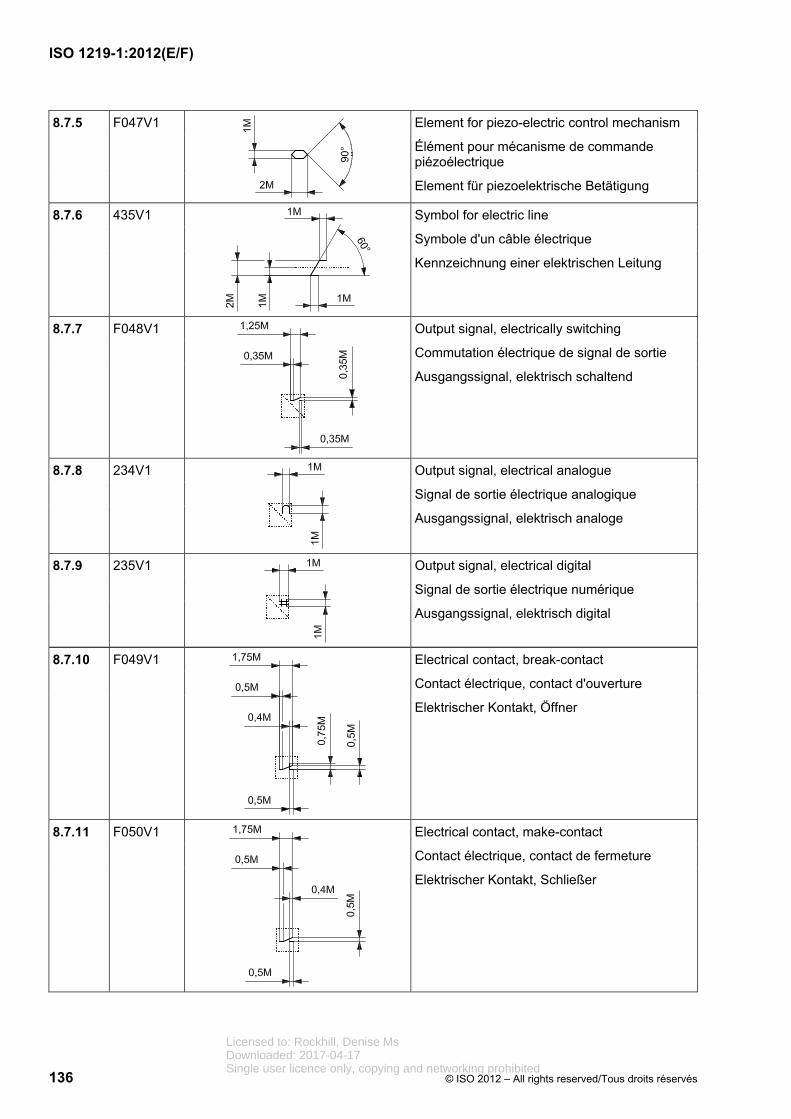
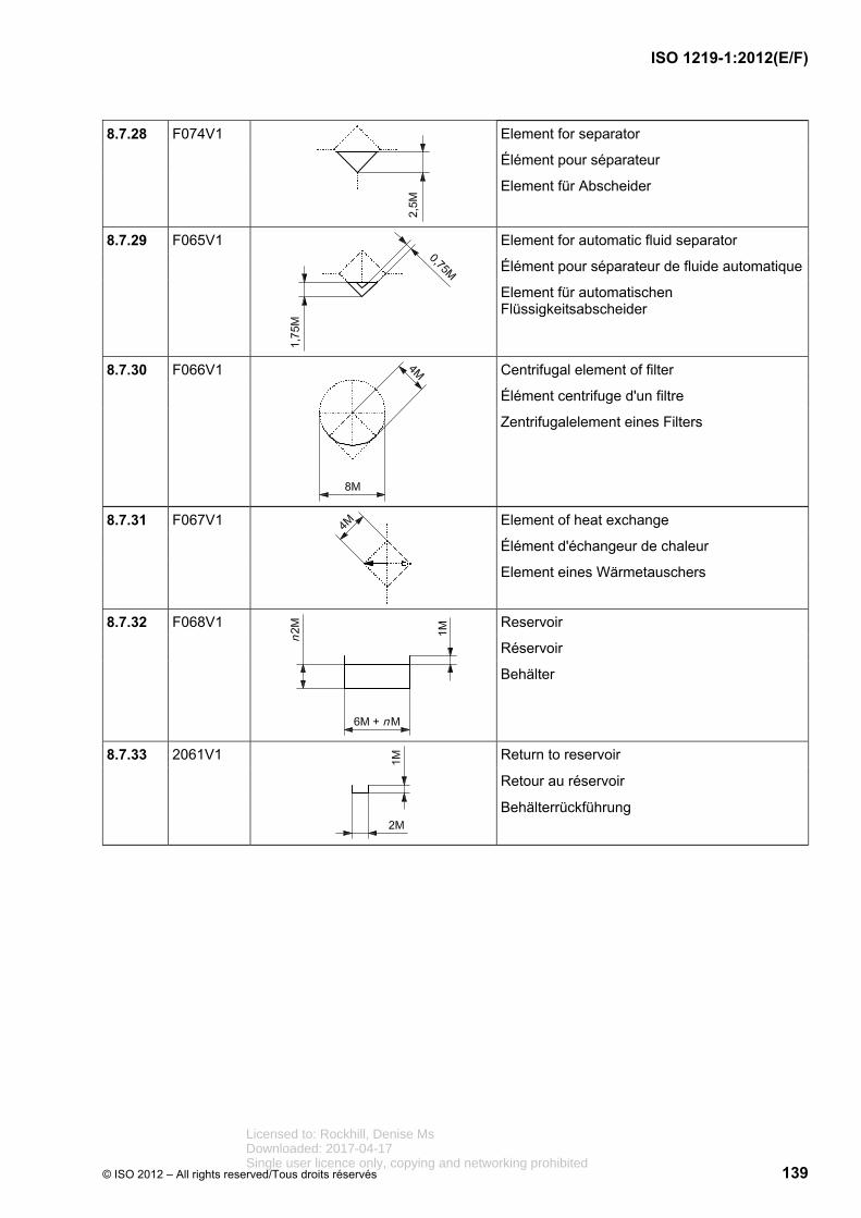
8 Symboles de base............................................................................................................................. 113 8.1 Traits .................................................................................................................................................. 113 8.2 Connexions et raccordements ........................................................................................................ 114 8.3 Voies d'écoulement et indicateurs de sens ................................................................................... 116 8.4 Éléments de base mécaniques ........................................................................................................ 119 8.5 Éléments de mécanismes de commande ....................................................................................... 129 8.6 Éléments de réglage ......................................................................................................................... 133 8.7 Accessoires ....................................................................................................................................... 135
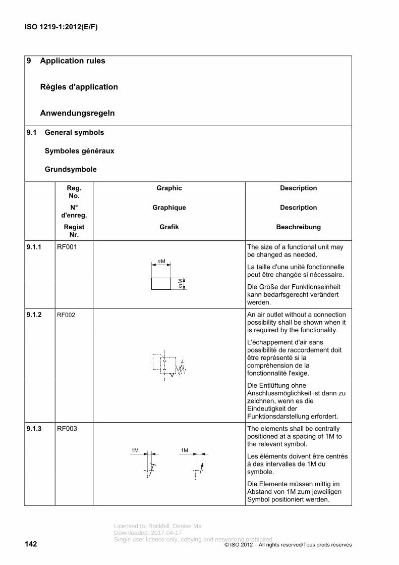
9 Règles d'application ......................................................................................................................... 142 9.1 Symboles généraux .......................................................................................................................... 142 9.2 Distributeurs ...................................................................................................................................... 143 9.3 Distributeurs à cartouche à bride à deux orifices ......................................................................... 152 9.4 Pompes et moteurs........................................................................................................................... 155 9.5 Vérins ................................................................................................................................................. 158 9.6 Accessoires ....................................................................................................................................... 160 9.6.1 Connexions et raccordements ........................................................................................................ 160 9.6.2 Équipement électrique ..................................................................................................................... 162 9.6.3 Appareils de mesurage et indicateurs ............................................................................................ 163 9.6.4 Sources d'énergie ............................................................................................................................. 164
Annexe A (informative) Recommandations pour la création des symboles de CAO ............................. 165
ISO (the International Organization for Standardization) is a worldwide federation of national standards bodies (ISO member bodies). The work of preparing International Standards is normally carried out through ISO technical committees. Each member body interested in a subject for which a technical committee has been established has the right to be represented on that committee. International organizations, governmental and non-governmental, in liaison with ISO, also take part in the work. ISO collaborates closely with the International Electrotechnical Commission (IEC) on all matters of electrotechnical standardization.
International Standards are drafted in accordance with the rules given in the ISO/IEC Directives, Part 2.
The main task of technical committees is to prepare International Standards. Draft International Standards adopted by the technical committees are circulated to the member bodies for voting. Publication as an International Standard requires approval by at least 75 % of the member bodies casting a vote.
Attention is drawn to the possibility that some of the elements of this document may be the subject of patent rights. ISO shall not be held responsible for identifying any or all such patent rights.
ISO 1219-1 was prepared by Technical Committee ISO/TC 131, Fluid power systems.
This third edition cancels and replaces the second edition (ISO 1219-1:2006), which has been technically revised.
ISO 1219 consists of the following parts, under the general title Fluid power systems and components — Graphical symbols and circuit diagrams:
Part 1: Graphical symbols for conventional use and data-processing applications
Part 2: Circuit diagrams
Licensed to: Rockhill, Denise MsDownloaded: 2017-04-17Single user licence only, copying and networking prohibited
L'ISO (Organisation internationale de normalisation) est une fédération mondiale d'organismes nationaux de normalisation (comités membres de l'ISO). L'élaboration des Normes internationales est en général confiée aux comités techniques de l'ISO. Chaque comité membre intéressé par une étude a le droit de faire partie du comité technique créé à cet effet. Les organisations internationales, gouvernementales et non gouvernementales, en liaison avec l'ISO participent également aux travaux. L'ISO collabore étroitement avec la Commission électrotechnique internationale (CEI) en ce qui concerne la normalisation électrotechnique.
Les Normes internationales sont rédigées conformément aux règles données dans les Directives ISO/CEI, Partie 2.
La tâche principale des comités techniques est d'élaborer les Normes internationales. Les projets de Normes internationales adoptés par les comités techniques sont soumis aux comités membres pour vote. Leur publication comme Normes internationales requiert l'approbation de 75 % au moins des comités membres votants.
L'attention est appelée sur le fait que certains des éléments du présent document peuvent faire l'objet de droits de propriété intellectuelle ou de droits analogues. L'ISO ne saurait être tenue pour responsable de ne pas avoir identifié de tels droits de propriété et averti de leur existence.
L'ISO 1219-1 a été élaborée par le comité technique ISO/TC 131, Transmissions hydrauliques et pneumatiques.
Cette troisième édition annule et remplace la deuxième édition (ISO 1219-1:2006), dont elle constitue une révision mineure.
L'ISO 1219 comprend les parties suivantes, présentées sous le titre général Transmissions hydrauliques et pneumatiques — Symboles graphiques et schémas de circuit:
Partie 1: Symboles graphiques en emploi conventionnel et informatisé
Partie 2: Schémas de circuit
Licensed to: Rockhill, Denise MsDownloaded: 2017-04-17Single user licence only, copying and networking prohibited
In fluid power systems, power is transmitted and controlled through a fluid (liquid or gas) under pressure within a circuit.
Graphical symbols are intended to describe fluid power components and their function. They are used in circuit diagrams, on nameplates, in catalogues and in other commercial literature.
Licensed to: Rockhill, Denise MsDownloaded: 2017-04-17Single user licence only, copying and networking prohibited
Dans les systèmes de transmissions hydrauliques et pneumatiques, l'énergie est transmise et commandée par l'intermédiaire d'un fluide (liquide ou gaz) sous pression circulant dans un circuit.
Les symboles graphiques servent à représenter les composants pour transmissions hydrauliques et pneumatiques ainsi que leur fonction. Ils figurent sur les schémas de circuit, les plaques signalétiques, les catalogues et les descriptions de produits.
Licensed to: Rockhill, Denise MsDownloaded: 2017-04-17Single user licence only, copying and networking prohibited
FINAL DRAFT INTERNATIONAL STANDARD PROJET FINAL DE NORME INTERNATIONALE
Fluid power systems and components — Graphical symbols and circuit diagrams —
Part 1: Graphical symbols for conventional use and data-processing applications
Transmissions hydrauliques et pneumatiques — Symboles graphiques et schémas de circuit —
Partie 1: Symboles graphiques en emploi conventionnel et informatisé
1 Scope
1 Domaine d'application
This part of ISO 1219 establishes basic elements for symbols. It specifies rules for devising fluid power symbols for use on components and in circuit diagrams.
This part of ISO 1219 is a collective application standard of the ISO 14617 series. In this part of ISO 1219, the symbols are designed in fixed dimensions to be used directly in data processing systems, which might result in different variants.
La présente partie de l'ISO 1219 définit des éléments de base pour symboles. Elle établit des règles de formation de symboles des transmissions hydrauliques et pneumatiques à utiliser sur les composants et les schémas de circuit.
La présente partie de l'ISO 1219 est une application collective de la série ISO 14617. Dans la présente partie de l'ISO 1219, les symboles sont dessinés avec des dimensions fixes pour être directement utilisés dans les systèmes de traitement de données, qui peuvent avoir comme conséquences différentes variantes.
NOTE In addition to terms in English and French, two of the three official ISO languages, this part of ISO 1219 gives the equivalent terms in German; these are published under the responsibility of the member body for Germany (DIN). However, only the terms and definitions given in the official languages can be considered as ISO terms and definitions.
NOTE En complément des termes en anglais et en français, deux des trois langues officielles de l'ISO, la présente partie de l'ISO 1219 donne les termes équivalents en allemand; ces termes sont publiés sous la responsabilité du comité membre allemand (DIN). Toutefois, seuls les termes et définitions donnés dans les langues officielles peuvent être considérés comme étant des termes et définitions de l'ISO.
Licensed to: Rockhill, Denise MsDownloaded: 2017-04-17Single user licence only, copying and networking prohibited
The following referenced documents are indispensable for the application of this document. For dated references, only the edition cited applies. For undated references, the latest edition of the referenced document (including any amendments) applies.
ISO 128 (all parts), Technical drawings — General principles of presentation
ISO 3098-5, Technical product documentation —Lettering — Part 5: CAD lettering of the Latin alphabet, numerals and marks
ISO 5598, Fluid power systems and components —Vocabulary
ISO 14617 (all parts), Graphical symbols for diagrams
ISO 81714-1, Design of graphical symbols for use in technical documentation of products — Part 1: Basic rules
IEC 81714-2, Design of graphical symbols for use in the technical documentation of products — Part 2: Specification for graphical symbols in a computer sensible form including graphical symbols for a reference library, and requirements for their interchange
2 Références normatives
Les documents de référence suivants sont indispensables pour l'application du présent document. Pour les références datées, seule l'édition citée s'applique. Pour les références non datées, la dernière édition du document de référence s'applique (y compris les éventuels amendements).
ISO 128 (toutes les parties), Dessins techniques —Principes généraux de représentation
ISO 3098-5, Documentation technique de produits —Écriture — Partie 5: Écriture en conception assistée par ordinateur de l'alphabet latin, des chiffres et des signes
ISO 5598, Transmissions hydrauliques et pneumatiques — Vocabulaire
ISO 14617 (toutes les parties), Symboles graphiques pour schémas
ISO 81714-1, Création de symboles graphiques à utiliser dans la documentation technique de produits — Partie 1: Règles fondamentales
CEI 81714-2, Création de symboles graphiques utilisables dans la documentation technique de produits — Partie 2: Spécification pour symboles graphiques sous forme adaptée à l'ordinateur, y compris les symboles pour bibliothèque de références, et exigences relatives à leur échange
Licensed to: Rockhill, Denise MsDownloaded: 2017-04-17Single user licence only, copying and networking prohibited
3 Terms and definitions 3 Termes et définitions 3 Begriffe und Definitionen
For the purposes of thisdocument, the terms and defini-tions given in ISO 5598 apply.
Pour les besoins du présentdocument, les termes et défini-tions donnés dans l'ISO 5598 s'appliquent.
Für die Anwendung diesesDokuments gelten die Begriffenach ISO 5598.
4 Identification statement (Reference to this part of ISO 1219)
4 Phrase d'identification (Référence à la présente partie de l'ISO 1219)
4 Kennzeichnungs-vermerk
Use the following statement in testreports, catalogues and salesliterature when claimingcompliance with this part ofISO 1219:
“Graphical symbols are inaccordance with ISO 1219-1:2012,Fluid power systems andcomponents — Graphical symbols and circuit diagrams — Part 1: Graphical symbols for conventionaluse and data-processing applications.”
Pour signaler la conformité à laprésente partie de l'ISO 1219, la phrase d'identification à utiliserdans les rapports d'essai,catalogues et documentation commerciale est la suivante:
«Les symboles graphiques sontconformes à l'ISO 1219-1:2012, Transmissions hydrauliques etpneumatiques — Symboles gra-phiques et schémas de circuit —Partie 1: Symboles graphiques en emploi conventionnel etinformatisé.»
Als Hinweis auf die Einhaltungdieses Teils der ISO 1219 ist derfolgende Text in Prüfberichten,Katalogen und Verkaufsunter-lagen zu verwenden:
„Die graphischen Symboleentsprechen ISO 1219-1:2012,Fluidtechnik — GraphischeSymbole und Schaltpläne — Teil 1:Graphische Symbole für konven-tionelle und datentechnischeAnwendungen.”
5 General rules
5 Règles générales
5 Allgemeine Regeln
5.1 Symbols for componentsare created using the symbols ofbasic nature specified in this partof ISO 1219 and taking intoaccount the rules given for theircreation.
5.1 Les symboles pour les composants sont à créer enutilisant les symboles de base spécifiés dans la présente partiede l'ISO 1219 et en tenant compte des règles données pour lacréation.
5.1 Symbole für Bauteile sindaus in diesem Teil von ISO 1219festgelegten Grundsymbolenunter Berücksichtigung dervorgegebenen Bildungsregeln zuerstellen.
5.2 Most symbols representcomponents and devices withspecified functions. Some sym-bols represent instead functions ormethods of operation.
5.2 La plupart des symboles représente des composants et des appareils aux fonctions défi-nies. Toutefois, certains symbolesreprésentent également des fonc-tions ou procédés de commande.
5.2 Die meisten Symbole stel-len Bauteile und Geräte mit fest-gelegten Funktionen dar. MancheSymbole stellen aber auch Funk-tionen oder Betätigungsverfahrendar.
5.3 Symbols are not intended toshow the actual construction of acomponent.
5.3 Les symboles ne visent pasà une représentation réelle d'uncomposant.
5.3 Symbole dienen nicht demZweck, die Konstruktion einesGerätes darzustellen.
Licensed to: Rockhill, Denise MsDownloaded: 2017-04-17Single user licence only, copying and networking prohibited
5.4 Symbols of componentsshow the de-energized (at-rest)position of a component. Symbolsof components that do not have aclearly defined de-energized (at-rest) position shall be createdaccording to the component-specific rules for the creation ofsymbols established in this part ofISO 1219.
NOTE The rules applicable tocircuit diagrams are given inISO 1219-2.
5.4 Les symboles descomposants présentent lescomposants en position repos.Les symboles des composants qui n'ont pas une position reposclairement définie doivent êtrecréés suivant les règles decréation de symboles spécifiquesà ces composants établies dansla présente partie de l'ISO 1219.
NOTE Les règles applicables aux schémas de circuits sont données dans l'ISO 1219-2.
5.4 Symbole zeigen die Ruhestellung eines Bauteils. Symbole für Bauteile, die keine eindeutige Ruhestellung haben, werden nach den in diesem Teil von ISO 1219 fixierten, bauteilspezifischen Bildungsregeln angelegt.
ANMERKUNG Die Regeln zur Erstellung von Schaltplänen sind in ISO 1219-2 enthalten.
5.5 Symbols of componentsshall show all the connectionsprovided.
5.5 Les symboles descomposants doivent présentertoutes les connexions prévues.
5.5 Symbole für Bauteile müssen alle vorhandenen An-schlüsse aufweisen.
5.6 Symbols shall have all therequired free spaces for indicatingthe port/connection designationsand parameters such as pressure,flow, electrical connection, etc., orcomponent settings.
5.6 Les symboles doiventcomporter toutes les cases libresnécessaires pour indiquer la dési-gnation de l'orifice/raccordementet de variables telles que lapression, le débit, leraccordement électrique, etc. ou les réglages des appareils.
5.6 Symbole müssen alle erfor-derlichen Platzhalter zur Angabe der Anschlussbezeichnung und der Angaben über Größen wie Druck, Volumenstrom, Elektroan-schluss usw. oder Geräteeinstel-lungen haben.
5.7 In accordance withISO 81714-1, symbols of basicnature may be mirrored or turnedwhen graphical symbols are beingcreated unless doing sotransforms them into an existingsymbol of basic nature.
5.7 Conformément à l'ISO 81714-1, les éléments de base peuvent être tournés ouinversés pour la création desymboles graphiques, tant qu’ils ne sont pas transformés en unélément de base existant.
5.7 Nach ISO 81714-1 dürfen Grundsymbole zur Bildung von graphischen Symbolen gedreht oder gespiegelt werden, solange sie nicht zu einem existierenden Grundsymbol werden.
5.8 The symbols are shown inthe original position as defined inthis part of ISO 1219 and inISO 81714-1. They may bemirrored or rotated in 90°increments without changing theirmeaning.
5.8 Les symboles sontprésentés dans la positionoriginelle, comme défini dans la présente partie de l'ISO 1219 et dans l'ISO 81714-1. Les symboles peuvent être inversés ou tournéspar pas de 90° sans incidence surleur signification.
5.8 Die Symbole sind in der Originallage, wie in diesem Teil von ISO 1219 und in ISO 81714-1 definiert, dargestellt. Sie dürfen ohne Einfluss auf ihre Bedeutung gespiegelt oder in Schritten von 90° gedreht werden.
Licensed to: Rockhill, Denise MsDownloaded: 2017-04-17Single user licence only, copying and networking prohibited
5.9 If a symbol represents afluid power component with two ormore main functions that areconnected to each other, thesymbol shall be enclosed by asolid line (see 8.1.1).
NOTE 1 For example, the duty ofcontrol mechanisms on directionalcontrol valves and indication ofclogging of a filter are not consideredmain functions.
NOTE 2 This is a change fromISO 1219-1:1991, in which the linewas dash-dotted. The reason for thechange is to improve clarity.
5.9 Lorsqu'un symbole detransmissions hydrauliques e
t
pneumatiques représente uncomposant doté de plusieursfonctions principales intercon-nectées, le symbole doit être entouré par un cadre en trait plein(voir 8.1.1).
NOTE 1 La commande des distributeurs ou l'indication du colmatage des filtres ne sont pas àconsidérer comme fonctionsprincipales.
NOTE 2 Ce point constitue un amendement par rapport àl'ISO 1219-1:1991, dans laquelle ce trait était mixte. La raison de cechangement est d'améliorer la clarté.
5.9 Wenn ein Symbol einfluidtechnisches Bauteil mitmehreren Hauptfunktionen, dieuntereinander verbunden sind,darstellt, ist das Symbol mit einerdurchgezogenen Linie zuumrahmen (siehe 8.1.1).
ANMERKUNG 1 Die Betätigungvon Wegeventilen und das Anzeigender Verschmutzung bei Filtern sindzum Beispiel nicht als Hauptfunktio-nen anzusehen.
ANMERKUNG 2 Das ist eineÄnderung gegenüber der vorange-gangenen Ausgabe von ISO 1219-1:1991, bei der diese Linie strich-punktiert dargestellt wurde. DieseÄnderung wurde vorgenommen, umdie Darstellung zu verdeutlichen.
5.10 Where two or morecomponents are contained in oneassembly, their symbols shall beenclosed by a dash-dotted narrow line (see 7.4.4.17).
5.10 Lorsqu'une unité réunit deux ou plusieurs composants,leurs symboles doivent être entourés par un cadre en trait mixte fin (voir 7.4.4.17).
5.10 Wenn zwei oder mehrBauteile in einer Einheit enthaltensind, müssen sie mit einerstrichpunktierten Linie eingerahmtwerden (siehe 7.4.4.17).
5.11 The dotted line used in thispart of ISO 1219 is employed forrepresenting adjacent basicelements or components. It is notused in graphical symbols.
5.11 Le trait en pointillés utilisé dans la présente partie del'ISO 1219 sert à représenter les éléments de base ou composantsadjacents. Il n'est pas utilisé dansles symboles graphiques.
5.11 Die in diesem Teil vonISO 1219 verwendete gepunkteteLinie wird zur Darstellungangrenzender Grundelementeoder Bauteile genutzt. Sie wirdnicht in Symbolen verwendet.
Licensed to: Rockhill, Denise MsDownloaded: 2017-04-17Single user licence only, copying and networking prohibited
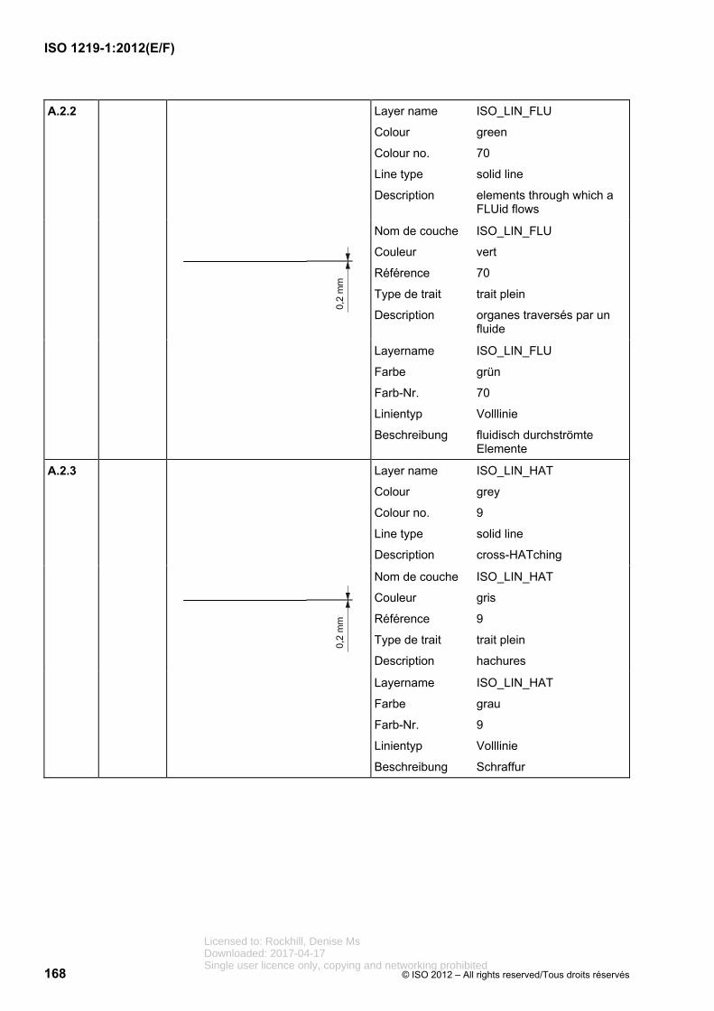
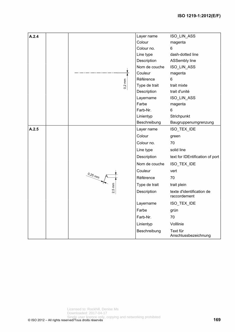
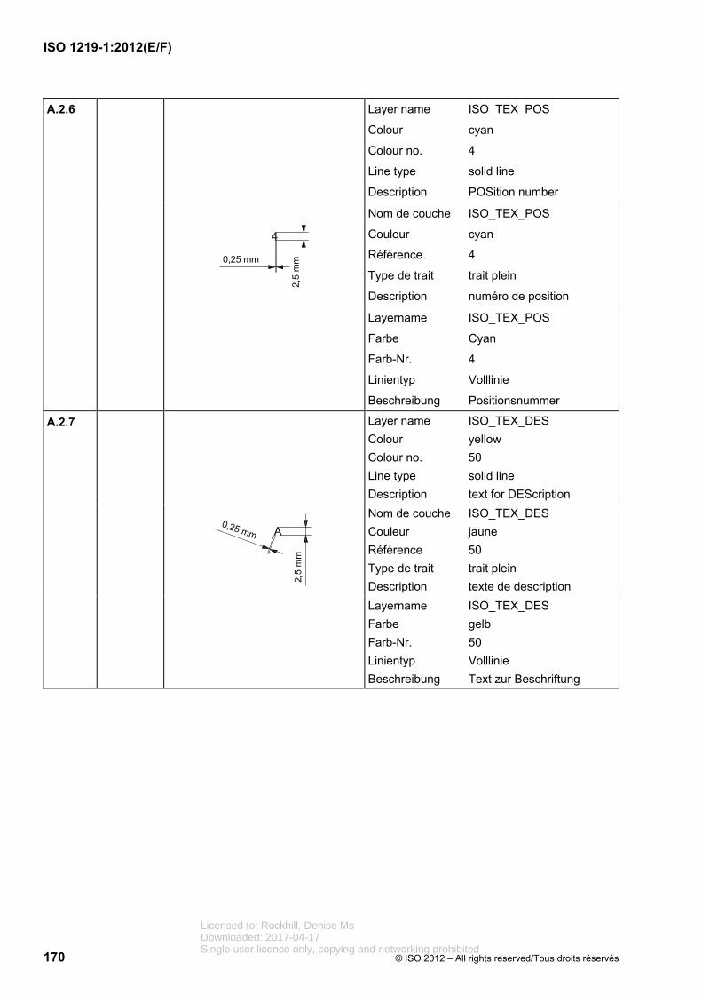
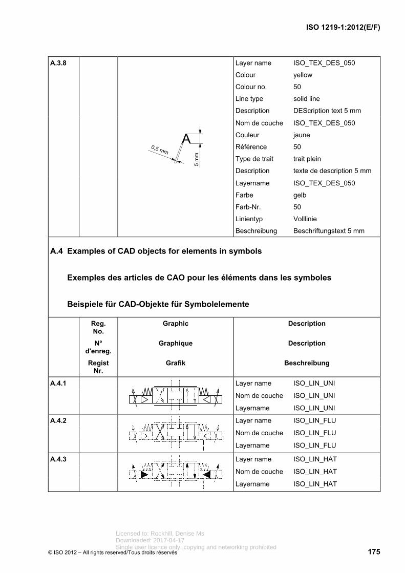
5.12 The graphical symbols inthis part of ISO 1219 are drawn inaccordance with ISO 14617 (allparts) and the rules inISO 81714-1 and IEC 81714-2.Graphical symbols in accordancewith ISO 14617 (all parts) aredrawn with a module sizeM = 2,5 mm and a line thicknessof 0,25 mm. To minimize symbolsize, graphical symbols in this partof ISO 1219 are drawn with amodule size M = 2,0 mm and aline thickness of 0,2 mm. For bothmodule sizes, however, letteringshall be 2,5 mm high with a linethickness of 0,25 mm. It ispossible to scale graphicalsymbols used on componentlabels or catalogues as required.
5.12 Les symboles graphiquescontenus dans la présente partie de l'ISO 1219 sont dessinés conformément à l'ISO 14617 (toutes les parties) et aux règlesde l'ISO 81714-1 et de la CEI 81714-2. Les symboles graphiques conformes à l'ISO 14617 (toutes les parties)sont dessinés avec une taille de module de M = 2,5 mm et une épaisseur de ligne de 0,25 mm. Afin de réduire la taille dessymboles, les symboles graphiques dans la présente partiede l'ISO 1219 sont dessinés avecune taille de module deM = 2,0 mm et une épaisseur deligne de 0,2 mm. Toutefois, pour les deux tailles de module la hauteur de lettres doit être de 2,5 mm et l'épaisseur de ligne de 0,25 mm. Il est possible de faireappel aux multiples requis pour lesplaques signalétiques ou lescatalogues.
5.12 Die graphischen Symbole in diesem Teil von ISO 1219 sind nach ISO 14617 (alle Teile) und nach den Regeln in ISO 81714-1 und IEC 81714-2 gezeichnet. Graphische Symbole in ISO 14617 (alle Teile) sind mit Modul M =2,5 mm und Linienbreite 0,25 mm gezeichnet. Um die Symbolgröße zu minimieren, werden die graphischen Symbole in diesem Teil von ISO 1219 miteinem Modul M = 2,0 mm und einer Linienbreite von 0,2 mm gezeichnet. Für beide Module gilt die Schriftgröße 2,5 mm mit einer Linienbreite von 0,25 mm. Für Typenschilder oder Kataloge dürfen erforderliche Skalierungen vorgenommen werden.
5.13 Dimensions of lettering andport labelling should be accordingto ISO 3098-5, character shapeCB.
5.13 Il convient que la taille deslettres et la désignation desorifices soient conformes àl'ISO 3098-5, écriture de type CB.
5.13 Die Maße der Beschriftung und Anschlussbezeichnungen sollten nach ISO 3098-5, Schriftform CB sein.
Licensed to: Rockhill, Denise MsDownloaded: 2017-04-17Single user licence only, copying and networking prohibited
5.14 Each graphical symbol inthis part of ISO 1219 is assigned aunique registration numberaccording to ISO 14617 (all parts).The variants are identified withV1, V2, V3, etc., after the registration number.
For registration numbers not yetspecified in ISO 14617 (all parts),a preliminary registration numberis used. For the field of fluid powerthe registration number isindicated by “F” for symbols ofbasic nature and by “RF” forapplication rules before thenumber.
Examples of symbols areindicated by “X”. The range fromX10000 to X39999 is reserved forthe field of fluid power technology.
5.14 Un numéro d'enregistrement unique est assigné à chaque symbole graphique de la présente partie de l'ISO 1219,conformément à l'ISO 14617 (toutes les parties). Les variantessont identifiées par V1, V2, V3, etc. après le numéro d'enregistrement.
Lorsqu'un numérod'enregistrement n'est pas encore spécifié dans l'ISO 14617 (toutes les parties), un numéro d'enregistrement provisoire est utilisé. Dans le domaine des transmissions hydrauliques etpneumatiques, les numérosd'enregistrement provisoire comportent, avant le numéro, soitun «F», pour les éléments de base, soit «RF», pour les règles d'application.
Les exemples de symboles sontindiqués par un «X», la plage des numéros compris entre X10000 et X39999 étant réservée au domaine des transmissionshydrauliques et pneumatiques.
5.14 Jedem graphischen Symbolin diesem Teil von ISO 1219 wirdeine eindeutige Registriernummernach ISO 14617 (alle Teile)zugeordnet. Varianten werden mitV1, V2, V3 usw. nach derRegistriernummer unterschieden.
Für noch nicht in ISO 14617 (alleTeile) festgelegte Registrier-nummern ist eine vorläufigeRegistriernummer angegeben, diefür die Fluidtechnik mit „F” fürGrundelemente und mit „RF” fürAnwendungsregeln beginnt.
Beispiele von Symbolen sind mit„X” gekennzeichnet. Für dieFluidtechnik ist derNummernbereich X10000 bisX39999 reserviert.
Licensed to: Rockhill, Denise MsDownloaded: 2017-04-17Single user licence only, copying and networking prohibited
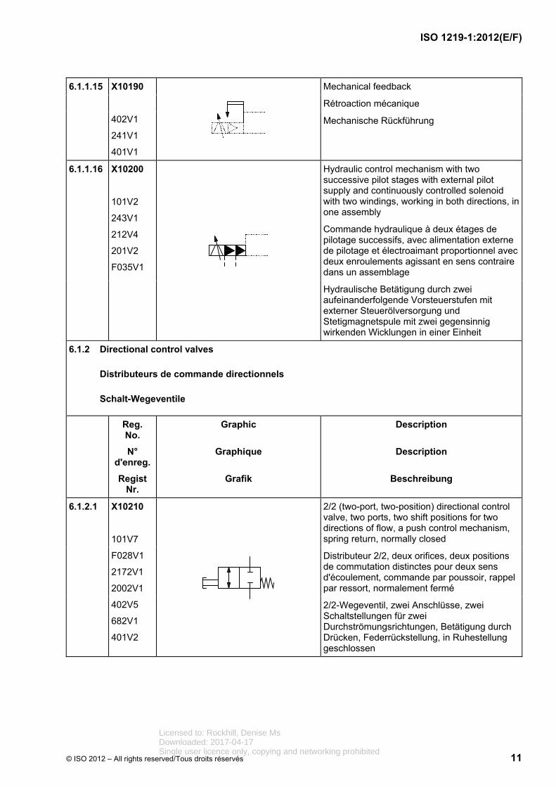
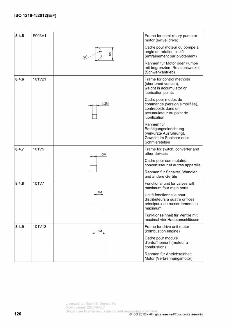
Hydraulic control mechanism with two successive pilot stages with external pilot supply and continuously controlled solenoid with two windings, working in both directions, in one assembly
Commande hydraulique à deux étages de pilotage successifs, avec alimentation externe de pilotage et électroaimant proportionnel avec deux enroulements agissant en sens contraire dans un assemblage
Hydraulische Betätigung durch zwei aufeinanderfolgende Vorsteuerstufen mit externer Steuerölversorgung und Stetigmagnetspule mit zwei gegensinnig wirkenden Wicklungen in einer Einheit
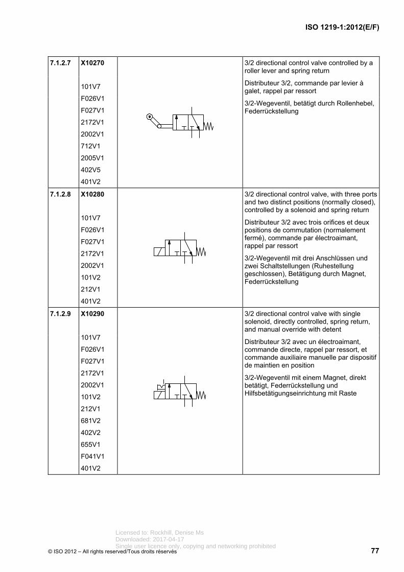
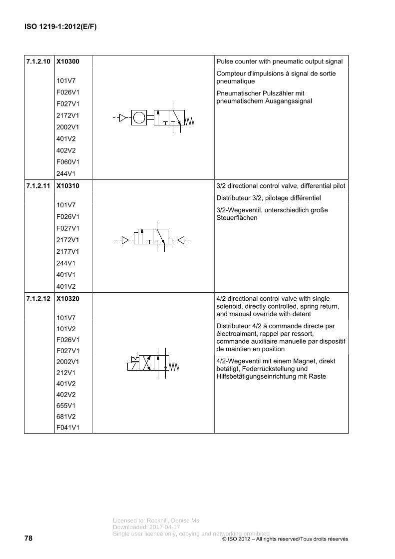
6.1.2 Directional control valves
Distributeurs de commande directionnels
Schalt-Wegeventile
Reg. No.
N° d'enreg.
Regist Nr.
Graphic
Graphique
Grafik
Description
Description
Beschreibung
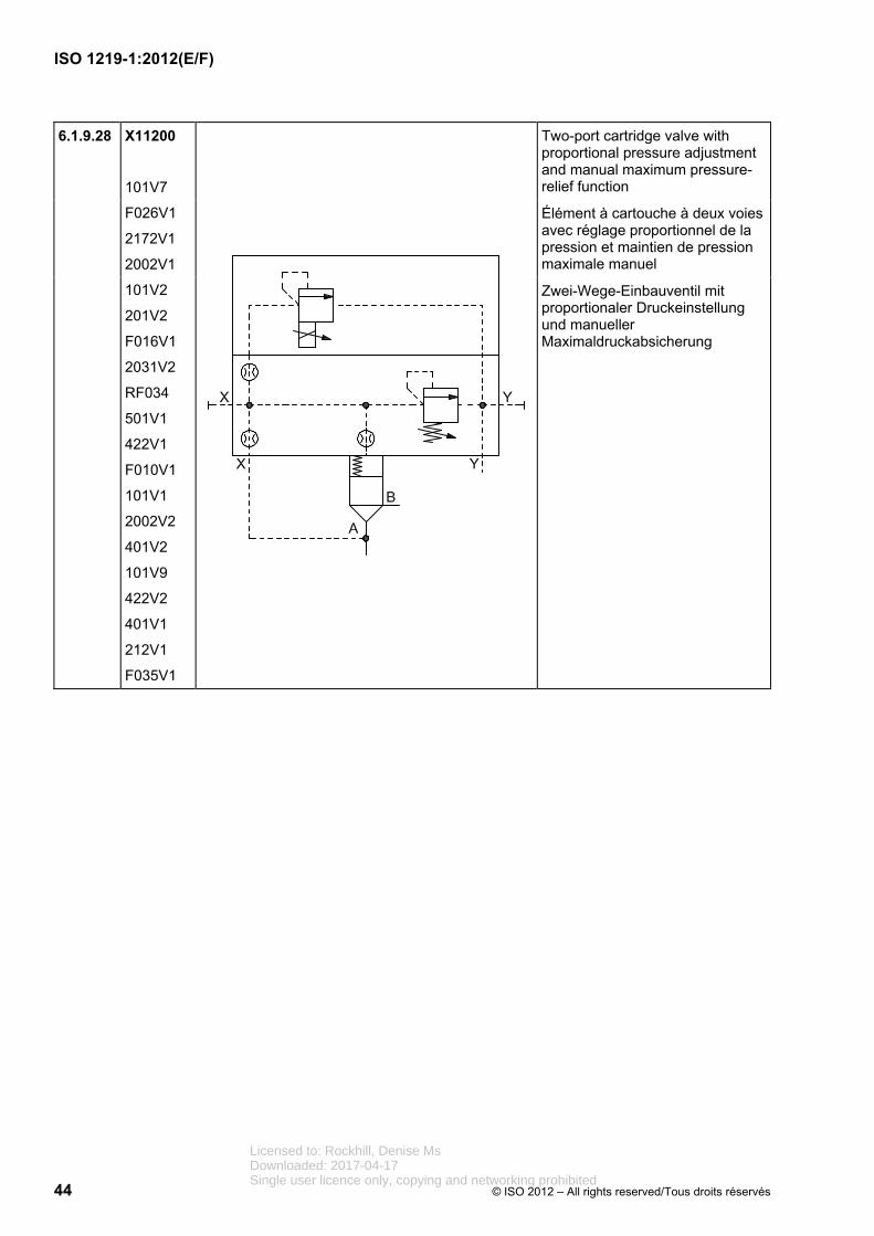
6.1.2.1 X10210
101V7
F028V1
2172V1
2002V1
402V5
682V1
401V2
2/2 (two-port, two-position) directional control valve, two ports, two shift positions for two directions of flow, a push control mechanism, spring return, normally closed
Distributeur 2/2, deux orifices, deux positions de commutation distinctes pour deux sens d'écoulement, commande par poussoir, rappel par ressort, normalement fermé
2/2-Wegeventil, zwei Anschlüsse, zwei Schaltstellungen für zwei Durchströmungsrichtungen, Betätigung durch Drücken, Federrückstellung, in Ruhestellung geschlossen
Licensed to: Rockhill, Denise MsDownloaded: 2017-04-17Single user licence only, copying and networking prohibited
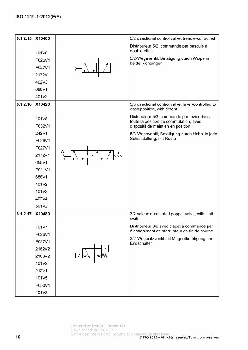
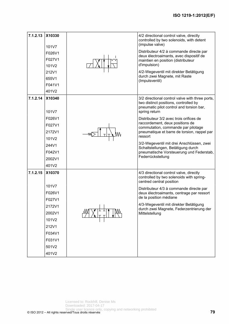
4/2 directional control valve, directly controlled by two solenoids, with detent (impulse valve)
Distributeur 4/2 à commande directe par deux électroaimants, avec dispositif de maintien en position (distributeur d'impulsion)
4/2-Wegeventil mit direkter Betätigung durch zwei Magnete, mit Raste (Impulsventil)
6.1.2.10 X10350
101V7
F026V1
F027V1
2002V1
101V2
243V1
212V1
401V2
4/2 directional control valve, two distinct positions, controlled by solenoid and hydraulic pilot, spring return
Distributeur 4/2, deux positions de commutation, commande par électroaimant et pilotage hydraulique, rappel par ressort
4/2-Wegeventil, zwei Schaltstellungen, Betätigung durch Magnet und hydraulische Vorsteuerung, Federrückstellung
6.1.2.11 X10360
101V2
101V7
F026V1
F027V1
2002V1
212V1
2172V1
243V1
401V2
F035V1
4/3 directional control valve, with electrical operation of the pilot stage and hydraulic operation of the main stage, main stage and pilot stage with spring-centring, external pilot supply and pilot drain
Distributeur 4/3, piloté, commande hydraulique de l'étage principal, commande électrique de l'étage de pilotage, étage principal et étage de pilotage à centrage par ressort, alimentation externe et retour externe de pilotage
4/3-Wegeventil, mit elektrischer Betätigung der Vorsteuerstufe und hydraulischer Betätigung der Hauptsstufe, Haupt- und Vorsteuerstufe mit Federzentrierung, Steuerölversorgung und Steuerölablauf extern
Licensed to: Rockhill, Denise MsDownloaded: 2017-04-17Single user licence only, copying and networking prohibited
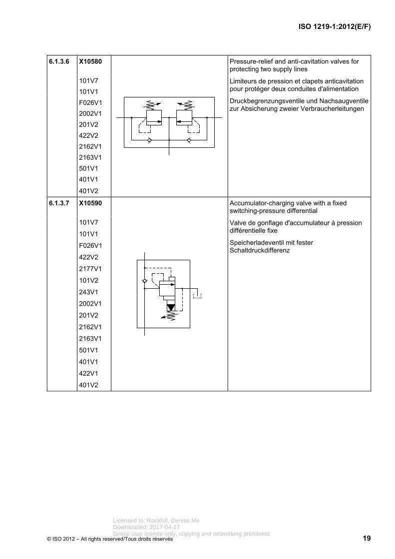
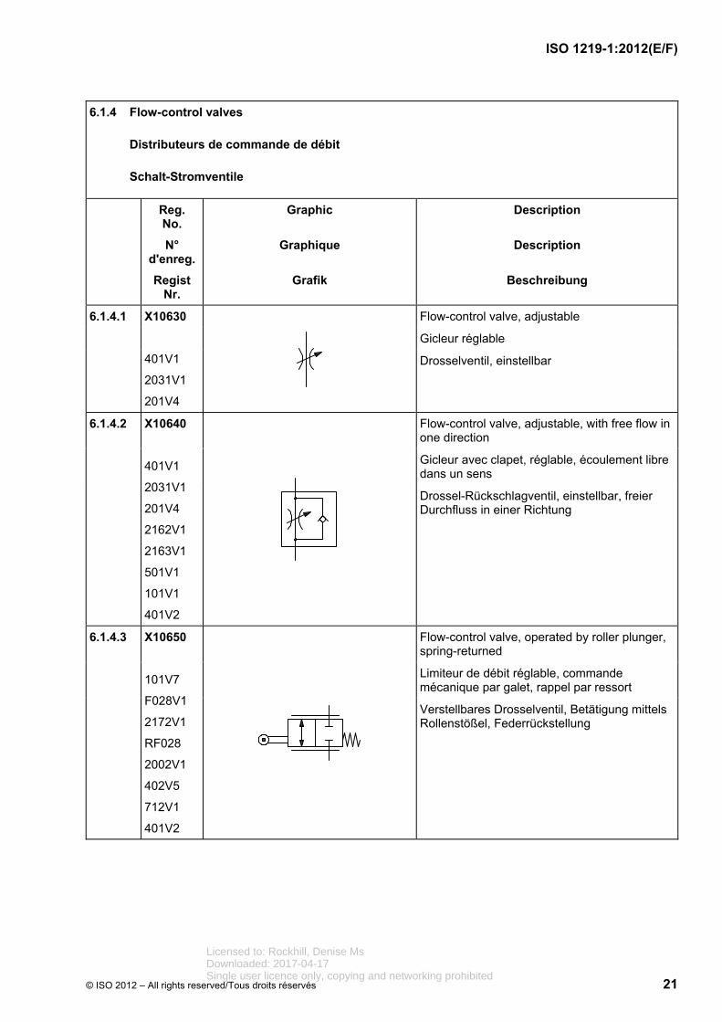
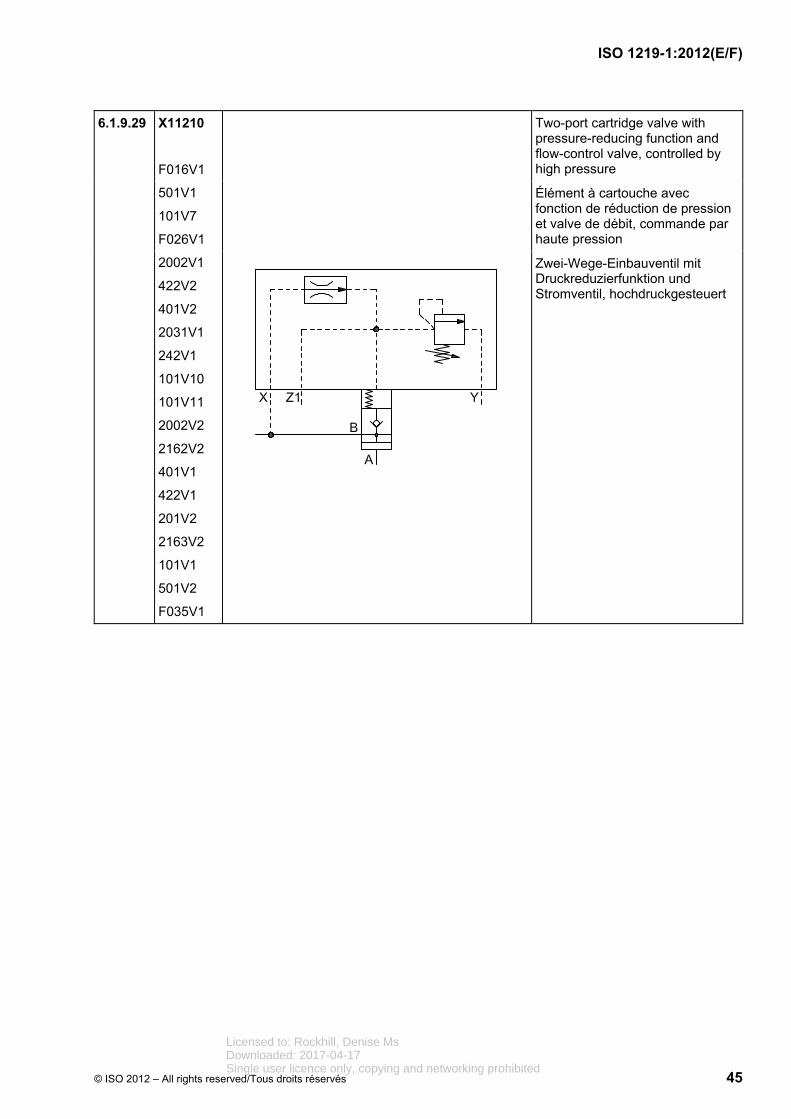
Two-port flow-control valve, preset, for one direction of flow, largely independent of viscosity and pressure differential, adjustable, with bypass check valve
Régulateur de débit à deux voies, à réglage fixe, pour un sens d'écoulement, peu sensible à la viscosité et à la pression différentielle, réglable, avec clapet antiretour de bipasse
Zwei-Wege-Stromventil, fest eingestellt, für eine Strömungsrichtung, weitgehend unabhängig von Viskosität und Druckdifferenz, einstellbar, mit Umgehungsrückschlagventil
6.1.4.5 X10670
F022V1
201V3
242V1
501V1
101V1
401V1
401V2
Three-port flow-control valve, adjustable, that divides the inlet flow into a fixed flow and a residual flow
Régulateur de débit à trois voies, réglable, qui divise le débit d'entrée entre un débit constant et un débit résiduel
Drei-Wege-Stromregelventil, einstellbar, teilt den Eingangsvolumenstrom in einen Konstant-strom und einen Reststrom
6.1.4.6 X10680
F022V1
242V1
101V1
401V1
501V2
401V2
Flow divider that divides the inlet flow into two outlet flows
Diviseur de débit qui divise le débit d'entrée en deux débits de sortie.
Volumenstromteiler teilt den Eingangsvolumenstrom in zwei Ausgangsvolumenströme.
6.1.4.7 X10690
F022V1
242V1
101V1
401V1
501V2
401V2
Flow-combining valve that maintains the two inlet flows constant in relation to each other
Sommateur de débit qui maintient deux débits d'entrée à une valeur constante l'un par rapport à l'autre.
Volumenstromsummierer hält zwei Eingangsvolumenströme zueinander konstant.
Licensed to: Rockhill, Denise MsDownloaded: 2017-04-17Single user licence only, copying and networking prohibited
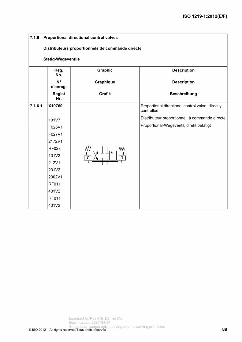
Servo-valve, pilot-operated, with closed-loop position control of the main and pilot stages, with integrated electronics
Servodistributeur piloté à commande avec régulation de la position de l'étage principal et de l'étage de pilotage, électronique intégrée
Servoventil vorgesteuert mit einem Stellmagneten, mit Lageregelung der Haupt- und der Vorsteuerstufe, mit integrierter Elektronik
6.1.6.5 X10800
101V7
F026V1
F027V1
F033V1
2031V2
RF028
101V2
243V1
212V4
201V2
402V1
241V1
401V2
501V2
101V5
F052V1
RF011
Servo-valve, pilot-operated, pilot stage with electrical control mechanism with two coils, continuously controlled in both directions, with mechanical feedback of the valve-spool position to the pilot stage, with integrated electronics
Servodistributeur piloté, étage pilote à dispositif électrique de commande à deux enroulements actifs en permanence dans les deux sens, à rappel mécanique de la position du tiroir de la valve sur l'étage de pilotage, électronique intégrée
Servoventil, vorgesteuert, Vorsteuerstufe mit elektrischer Betätigungseinrichtung mit zwei Wicklungen in beiden Richtungen stetig wirkend, mit mechanischer Rückführung der Lage des Ventilschiebers auf die Vorsteuerstufe, mit integrierter Elektronik
Licensed to: Rockhill, Denise MsDownloaded: 2017-04-17Single user licence only, copying and networking prohibited
Electro-hydraulic linear drive consisting of cylinder with servo-valve and stepping motor, mechanical feedback of the cylinder position
Entraînement linéaire électrohydraulique, composé du vérin et du servodistributeur avec moteur pas à pas, rétroaction mécanique de la position du vérin
Elektrohydraulischer Linearantrieb, bestehend aus Zylinder und Servoventil mit Schrittmotor, mechanische Rückführung der Zylinderposition
6.1.6.7 X10820
101V7
F026V1
F027V1
2172V1
RF028
F034V1
2002V1
101V2
212V1
201V2
101V5
F052V1
753V1
F045V1
234V1
501V2
401V2
F046V1
Servo-valve with preferred position in case of a power failure, electrical feedback and integral electronics
Servodistributeur avec position préférentielle en cas de panne de courant, rétroaction électrique, électronique intégrée
Servoventil mit Vorzugsstellung bei Stromausfall, elektrischer Rückführung und integrierter Elektronik
Licensed to: Rockhill, Denise MsDownloaded: 2017-04-17Single user licence only, copying and networking prohibited
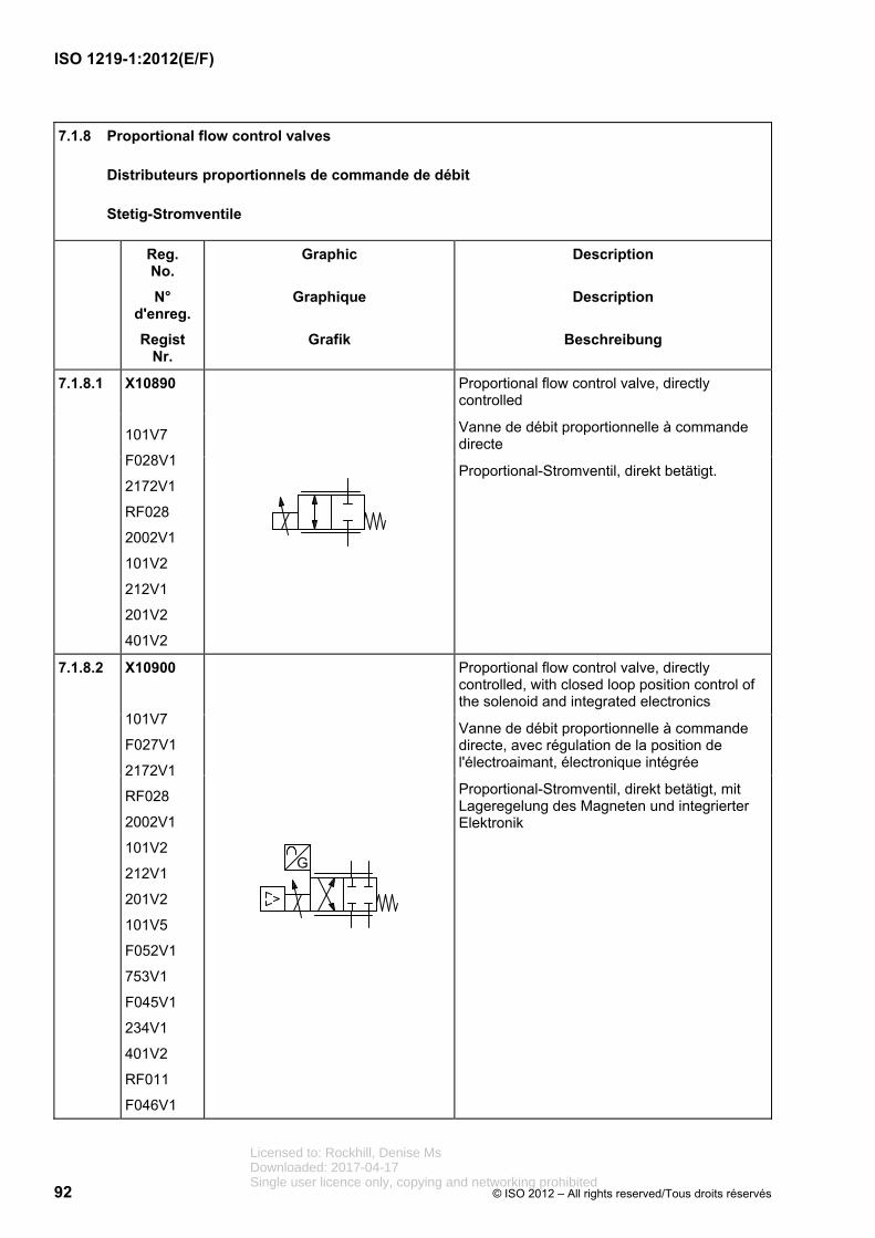
Three-port proportional pressure-reducing valve with closed-loop position control of the solenoid and integrated electronics
Réducteur de pression proportionnel trois voies, piloté, avec régulation de la position de l'électroaimant, électronique intégrée
Drei-Wege-Proportional-Druckreduzierventil, vorgesteuert, mit Lageregelung des Magneten und integrierter Elektronik
6.1.7.6 X10880
101V7
F026V1
101V2
243V1
212V1
201V2
101V5
F052V1
422V2
401V2
2002V1
Proportional pressure-relief valve, pilot-operated, with integral electronics and additional pilot stage for manual pressure adjustment or maximum pressure-relief function, with external drain
Limiteur de pression proportionnel, piloté, avec électronique intégrée et étage de pilotage supplémentaire pour réglage manuel de pression ou limitation de pression maximale de sécurité, à drain externe
Proportional-Druckbegrenzungsventil, vorgesteuert, mit integrierter Elektronik, mit zusätzlicher Vorsteuerstufe für manuelle Druckeinstellung bzw. Maximaldruck-Absicherung, mit externem Ölablauf
Licensed to: Rockhill, Denise MsDownloaded: 2017-04-17Single user licence only, copying and networking prohibited
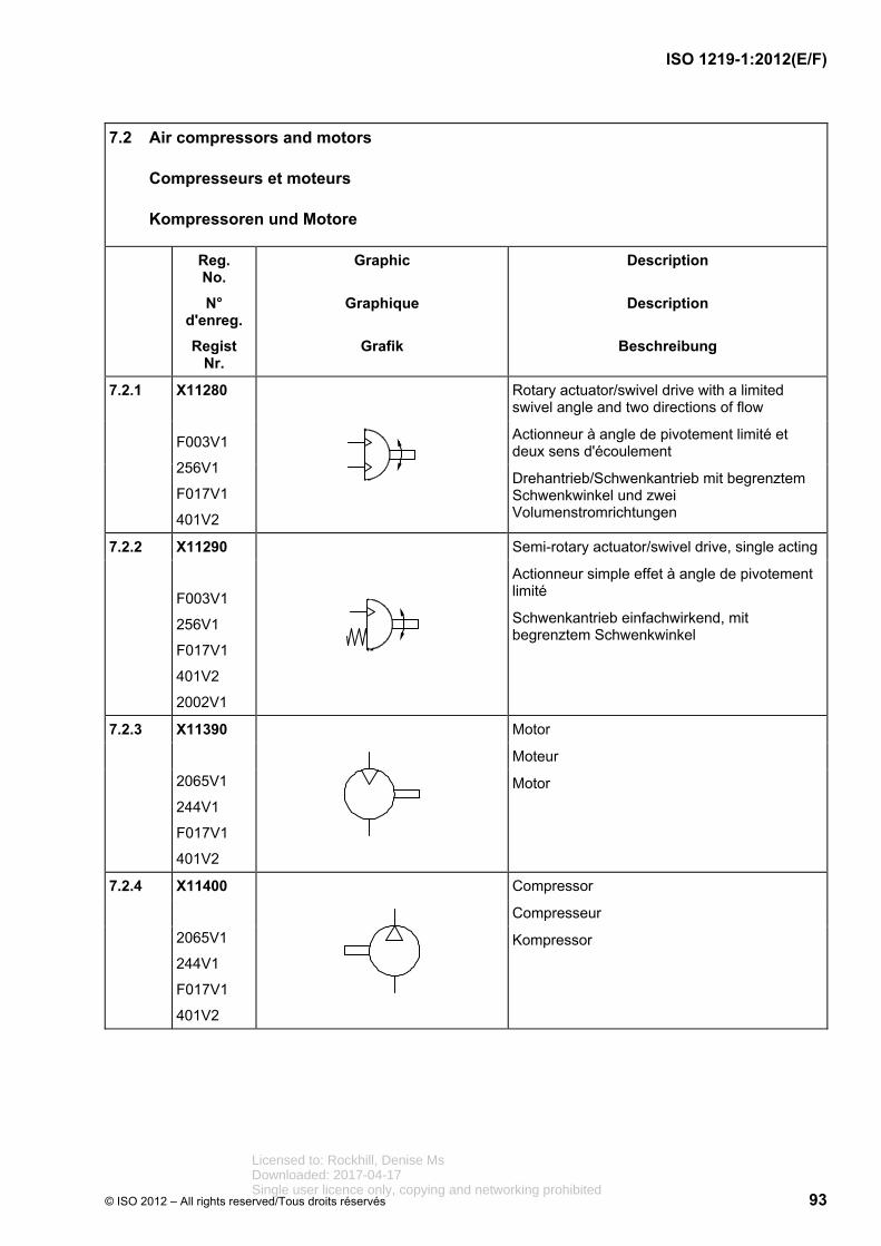
Variable-displacement pump and one direction of rotation (clockwise)
Pompe à cylindrée variable et à un sens (des aiguilles d’une montre)
Pumpe mit veränderlichem Fördervolumen und einer Drehrichtung (im Uhrzeigersinn)
6.2.2 X11240
2065V1
243V1
F017V1
201V5
401V2
255V1
422V1
F035V1
Variable-displacement pump with two directions of flow, external drain line, and one direction of rotation (clockwise)
Pompe à cylindrée variable à deux sens d'écoulement, drain externe et à un sens de rotation (des aiguilles d'une montre)
Verstellpumpe mit wechselnder Förderstromrichtung, externer Leckölleitung und einer Drehrichtung (im Uhrzeigersinn)
6.2.3 X11250
2065V1
243V2
F017V1
201V5
401V2
256V1
422V1
F035V1
Reversible pump/motor unit with two directions of flow and variable displacement, external drain line, and two directions of rotation
Groupe motopompe réversible à deux sens d'écoulement et cylindrée variable, drain externe et deux sens de rotation
Reversierbare Pumpe/Motor-Einheit mit zwei Volumenstromrichtungen und veränderlichem Verdrängungsvolumen, externe Leckölleitung und zwei Drehrichtungen
Licensed to: Rockhill, Denise MsDownloaded: 2017-04-17Single user licence only, copying and networking prohibited
Variable-displacement pump with combined pressure/flow control (load-sensing type), one drive direction (clockwise) and an external drain line
Pompe à cylindrée variable avec régulateur combiné de pression/débit (type à détection de charge), à un sens d'entraînement (des aiguilles d'une montre) et drain externe
Verstellpumpe mit kombiniertem Druck-/Stromregler (load sensing type), einer Antriebsrichtung (im Uhrzeigersinn) und externer Leckölleitung
6.2.10 X11320
2065V1
F017V1
201V5
401V2
255V2
422V1
101V2
101V1
243V1
402V5
681V2
401V1
F035V1
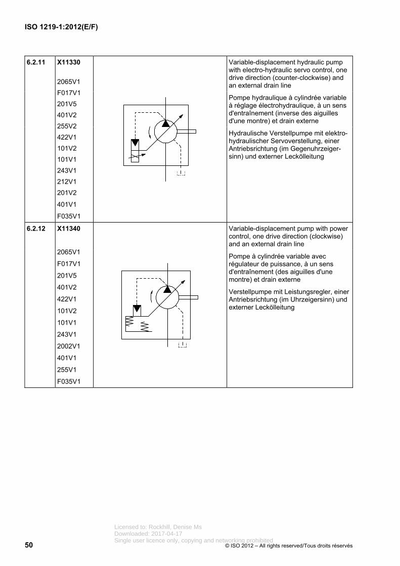
Variable-displacement pump with mechanical/hydraulic servo-control, one drive direction (counter-clockwise) and an external drain line
Pompe à cylindrée variable à réglage hydromécanique, à un sens d'entraînement (inverse des aiguilles d'une montre) et drain externe
Verstellpumpe mit mechanisch-hydraulischer Servoverstellung, einer Antriebsrichtung (im Gegenuhrzeiger-sinn) und externer Leckölleitung
Licensed to: Rockhill, Denise MsDownloaded: 2017-04-17Single user licence only, copying and networking prohibited
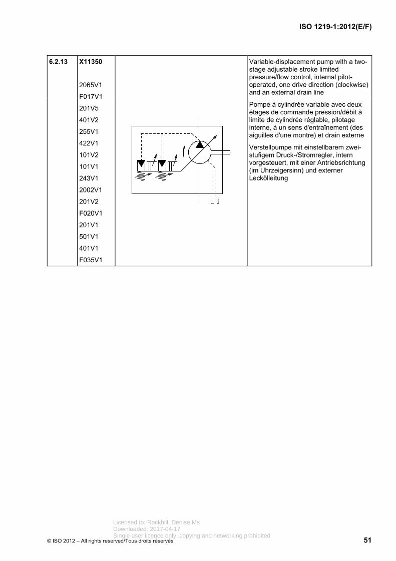
Variable-displacement pump with a two-stage adjustable stroke limited pressure/flow control, internal pilot-operated, one drive direction (clockwise) and an external drain line
Pompe à cylindrée variable avec deux étages de commande pression/débit à limite de cylindrée réglable, pilotage interne, à un sens d'entraînement (des aiguilles d'une montre) et drain externe
Verstellpumpe mit einstellbarem zwei-stufigem Druck-/Stromregler, intern vorgesteuert, mit einer Antriebsrichtung (im Uhrzeigersinn) und externer Leckölleitung
Licensed to: Rockhill, Denise MsDownloaded: 2017-04-17Single user licence only, copying and networking prohibited
Variable-displacement pump with a two-stage adjustable limited-stroke pressure/flow-control element, electrical switchover, one drive direction (clockwise) and an external drain line
Pompe à cylindrée variable avec régulateur de pression/débit à deux positions, à commutation électrique, à un sens d'entraînement (des aiguilles d’une montre) et drain externe
Verstellpumpe mit einstellbarem zweistufigem Druck-/Stromregler, elektrisch umsteuerbar, mit einer Antriebsrichtung (im Uhrzeigersinn) und externer Leckölleitung
6.2.15 X11370
2065V1
243V1
F017V1
201V5
255V1
101V1
401V1
256V1
Hydrostatic transmission (simplified representation), drive unit consisting of one reversible, variable-displacement pump with one input direction of rotation and one fixed displacement motor with two output directions of rotation
Transmission hydrostatique (représentation simplifiée), module d'entraînement composé d'une pompe à cylindrée variable à un sens d'entraînement en rotation et moteur à cylindrée fixe à deux sens de rotation de sortie
Kompaktgetriebe (vereinfachte Darstellung), Antriebseinheit bestehend aus reversiebler Verstellpumpe mit einer Antriebsdrehrichtung und Konstantmotor mit zwei Abtriebsdrehrichtungen
Licensed to: Rockhill, Denise MsDownloaded: 2017-04-17Single user licence only, copying and networking prohibited
Variable-displacement pump with one drive direction (clockwise) and description of the control and adjustment elements. The arrows indicating adjustability may be extended, and the control mechanisms and elements may be connected on either end of the arrow.
*** Short designation of complex controllers
Pompe à cylindrée variable à un sens d'entraînement (des aiguilles d’une montre) et descriptif de l'organe de commande et de réglage. Les flèches représentant le réglage peuvent être prolongées et les actionneurs et éléments de commande peuvent être rattachés à l'une des extrémités de la flèche.
*** Abréviation des régulateurs complexes
Verstellpumpe mit einer Antriebsrichtung (im Uhrzeigersinn) und textueller Beschreibung der Regel- und Verstelleinrichtung. Die Pfeile zur Darstellung der Verstellbarkeit können verlängert und die Betätigungs- und Regelelemente angebunden werden, entweder am Pfeilende oder an der Pfeilspitze.
*** Kurzbezeichnung komplexer Regler
6.2.17 X11430
2065V1
243V2
244V2
401V2
401V1
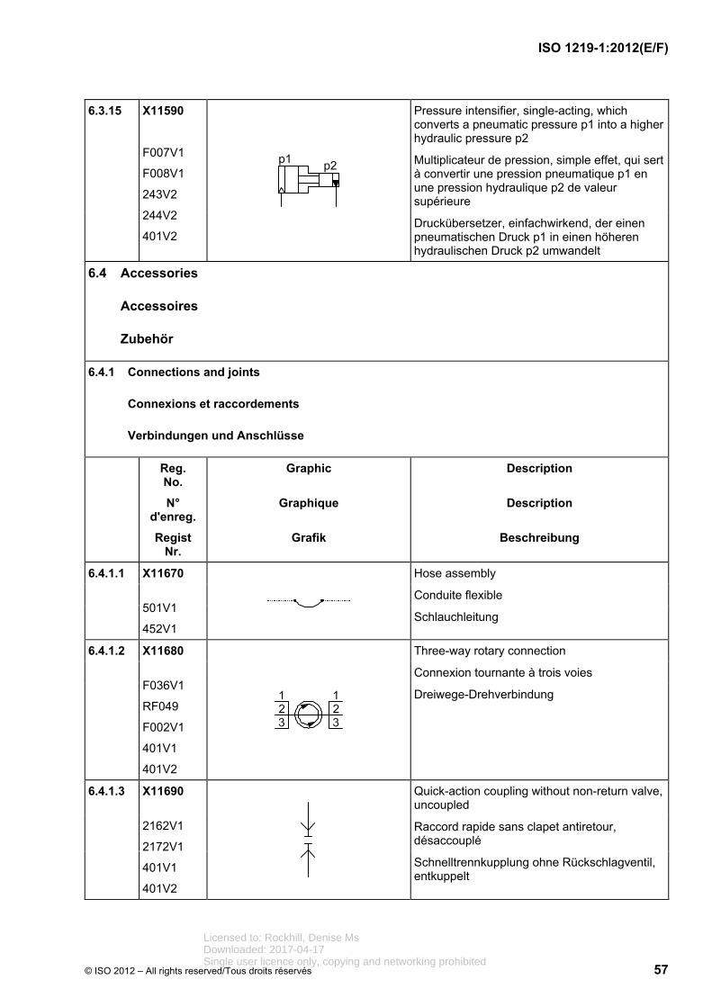
Pressure intensifier, continuous, which converts a pneumatic pressure p1 into a higher hydraulic pressure p2
Multiplicateur de pression, à effet continu, qui sert à convertir une pression pneumatique p1 en une pression hydraulique p2 de valeur supérieure
Druckübersetzer, kontinuierlich, der einen pneumatischen Druck p1 in einen höheren hydraulischen Druck p2 umwandelt
Licensed to: Rockhill, Denise MsDownloaded: 2017-04-17Single user licence only, copying and networking prohibited
Single-acting, single-rod cylinder, return stroke by spring force, spring chamber with connection
Vérin simple effet, à simple tige, rappel par ressort avec retour de fuite côté ressort
Einfachwirkender Zylinder, mit einseitiger Kolbenstange, Rückhub durch Federkraft, Federraum mit Anschluss
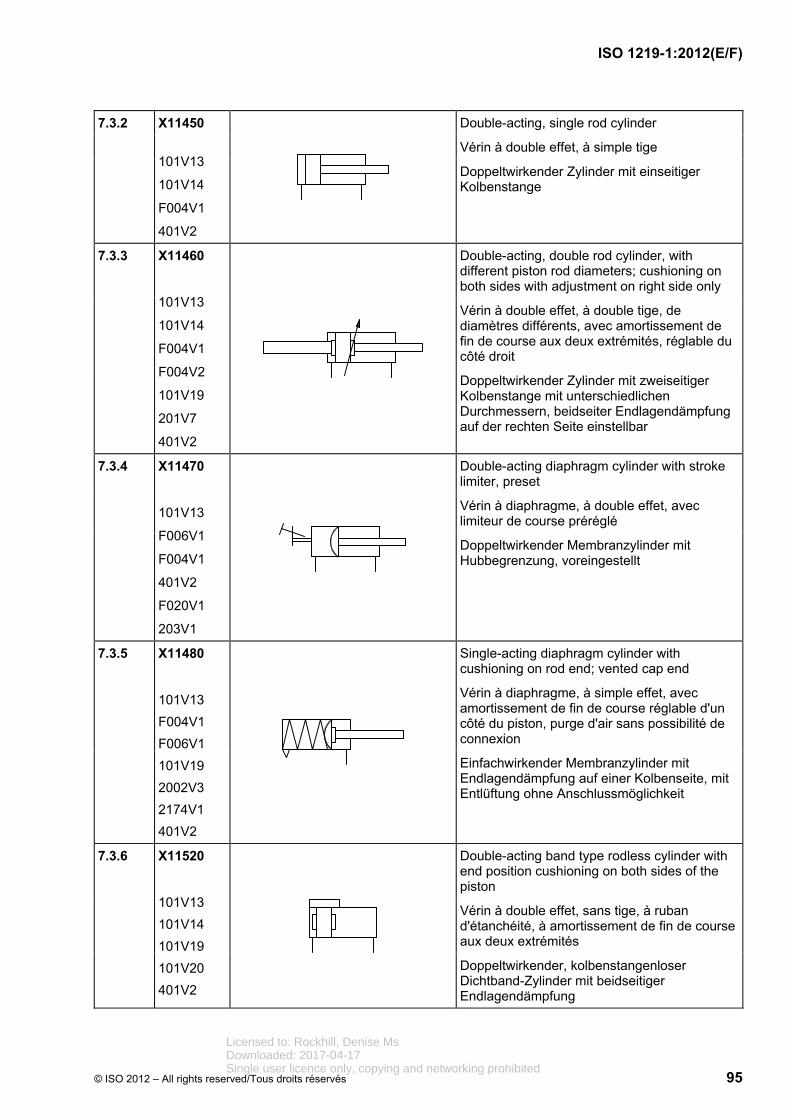
6.3.2 X11450
101V13
101V14
F004V1
401V2
Double-acting, single-rod cylinder
Vérin à double effet, à simple tige
Doppeltwirkender Zylinder mit einseitiger Kolbenstange
6.3.3 X11460
101V13
101V14
F004V1
F004V2
101V19
201V7
401V2
Double-acting, double-rod cylinder, with different piston-rod diameters; cushioning on both sides with adjustment on right side only
Vérin à double effet, à double tige, de diamètres différents, avec amortissement de fin de course aux deux extrémités réglable du côté droit
Doppeltwirkender Zylinder mit zweiseitiger Kolbenstange mit unterschiedlichen Durchmessern, beidseitiger Endlagendämpfung auf der rechten Seite einstellbar
6.3.4 X11470
101V13
F006V1
F004V1
401V2
F020V1
203V1
Double-acting diaphragm cylinder with preset stroke limiter
Vérin à diaphragme, à double effet, avec limiteur de course préréglé
Doppeltwirkender Membranzylinder mit Hubbegrenzung, voreingestellt
Licensed to: Rockhill, Denise MsDownloaded: 2017-04-17Single user licence only, copying and networking prohibited
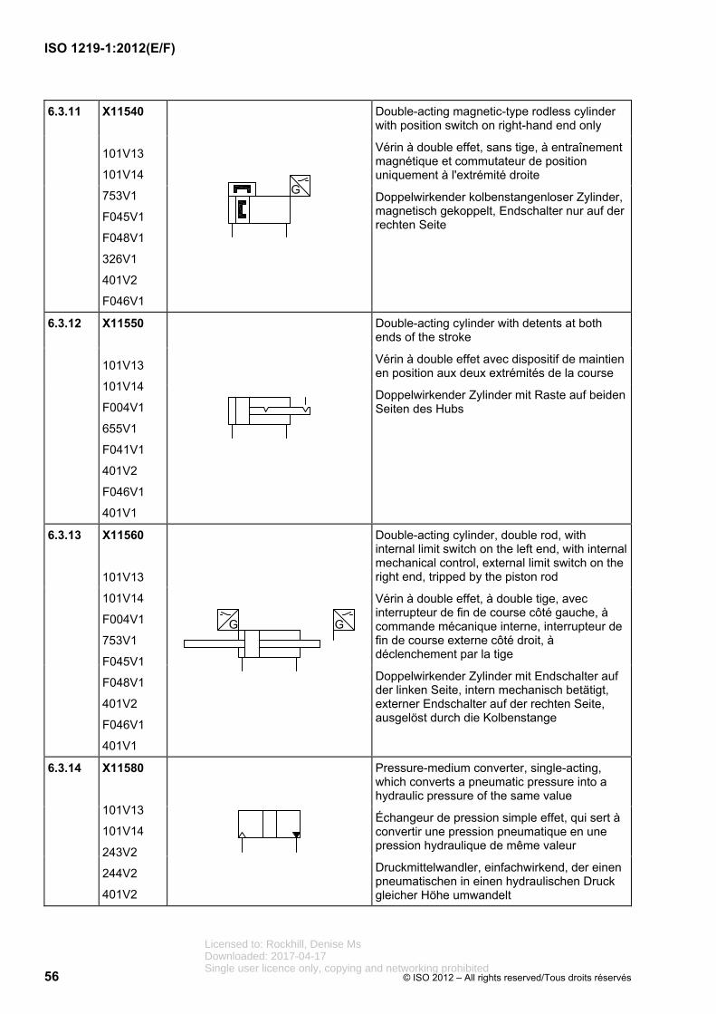
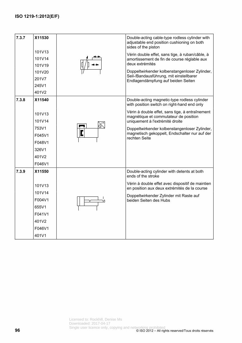
Double-acting magnetic-type rodless cylinder with position switch on right-hand end only
Vérin à double effet, sans tige, à entraînement magnétique et commutateur de position uniquement à l'extrémité droite
Doppelwirkender kolbenstangenloser Zylinder, magnetisch gekoppelt, Endschalter nur auf der rechten Seite
6.3.12 X11550
101V13
101V14
F004V1
655V1
F041V1
401V2
F046V1
401V1
Double-acting cylinder with detents at both ends of the stroke
Vérin à double effet avec dispositif de maintien en position aux deux extrémités de la course
Doppelwirkender Zylinder mit Raste auf beiden Seiten des Hubs
6.3.13 X11560
101V13
101V14
F004V1
753V1
F045V1
F048V1
401V2
F046V1
401V1
Double-acting cylinder, double rod, with internal limit switch on the left end, with internal mechanical control, external limit switch on the right end, tripped by the piston rod
Vérin à double effet, à double tige, avec interrupteur de fin de course côté gauche, à commande mécanique interne, interrupteur de fin de course externe côté droit, à déclenchement par la tige
Doppelwirkender Zylinder mit Endschalter auf der linken Seite, intern mechanisch betätigt, externer Endschalter auf der rechten Seite, ausgelöst durch die Kolbenstange
6.3.14 X11580
101V13
101V14
243V2
244V2
401V2
Pressure-medium converter, single-acting, which converts a pneumatic pressure into a hydraulic pressure of the same value
Échangeur de pression simple effet, qui sert à convertir une pression pneumatique en une pression hydraulique de même valeur
Druckmittelwandler, einfachwirkend, der einen pneumatischen in einen hydraulischen Druck gleicher Höhe umwandelt
Licensed to: Rockhill, Denise MsDownloaded: 2017-04-17Single user licence only, copying and networking prohibited
2/2 (two-port, two-position) directional control valve, two ports, two shifted positions for two directions of flow, push control mechanism, spring return, normally closed
Distributeur 2/2, deux orifices, deux positions de commutation distinctes pour deux sens d'écoulement, commande par poussoir, rappel par ressort, normalement fermé
2/2-Wegeventil, zwei Anschlüsse, zwei Schaltstellungen für zwei Durchströmungsrichtungen, Betätigung durch Drücken, Federrückstellung, in Ruhestellung geschlossen
7.1.2.2 X10220
101V7
F028V1
2002V1
101V2
212V1
2172V1
401V2
2/2 directional control valve, two ports, two shifted positions, normally open, solenoid-actuated, spring return
Distributeur 2/2, deux orifices, deux positions de commutation, normalement ouvert, commande par électroaimant, rappel par ressort
2/2-Wegeventil, zwei Anschlüsse, zwei Schaltstellungen, in Ruhestellung offen, Magnetbetätigung, Federrückstellung
7.1.2.3 X10230
101V7
F026V1
F027V1
2002V1
101V2
212V1
401V2
4/2 solenoid-actuated directional control valve, spring return
Distributeur 4/2 à commande par électroaimant, rappel par ressort
4/2-Wegeventil mit Magnetbetätigung, Federrückstellung
Licensed to: Rockhill, Denise MsDownloaded: 2017-04-17Single user licence only, copying and networking prohibited
Pneumatic soft-start valve, solenoid-operated, with internal pilot supply
Soupape pneumatique de démarrage progressif, commande électrique, avec alimentation par pilote interne
Pneumatisches Anfahrventil, elektrisch betätigt mit interner Steuerdruckversorgung
7.1.2.5 X10250
101V1
101V7
2172V1
F026V1
101V2
244V1
2031V1
201V4
501V1
2002V1
422V1
Pneumatic slow-start valve that is fitted at the inlet to a system, which allows fluid to enter the system at a reduced flow rate, until a pre-set pressure level is achieved, causing the valve to open to a full-flow condition
Soupape pneumatique de démarrage progressif, pourvue à l'entrée d'un système autorisant l'entrée du fluide à un débit réduit jusqu'au niveau de pression de réglage, entraînant l'ouverture de la soupape pour un débit maximal
Pneumatisches Druckaufbau- /Anfahrventil, das am Eingang eines Systems angeordnet wird und den Zustrom eines verringerten Volumenstroms ermöglicht, bis ein voreingestellter Druck erreicht ist, bei dem das Ventil öffnet und den vollen Volumenstrom durchlässt
7.1.2.6 X10260
101V7
F026V1
F027V1
2172V1
402V5
682V1
F039V1
401V2
3/2 lockout valve with padlock
Distributeur 3/2 à commande verrouillable avec cadenas
3/2-Wegeventil mit abschließbarer Betätigung mit Vorhängeschloss
Licensed to: Rockhill, Denise MsDownloaded: 2017-04-17Single user licence only, copying and networking prohibited
4/2 directional control valve, directly controlled by two solenoids, with detent (impulse valve)
Distributeur 4/2 à commande directe par deux électroaimants, avec dispositif de maintien en position (distributeur d'impulsion)
4/2-Wegeventil mit direkter Betätigung durch zwei Magnete, mit Raste (Impulsventil)
7.1.2.14 X10340
101V7
F026V1
F027V1
2172V1
101V2
244V1
F042V1
2002V1
401V2
3/2 directional control valve with three ports, two distinct positions, controlled by pneumatic pilot control and torsion bar, spring return
Distributeur 3/2 avec trois orifices de raccordement, deux positions de commutation, commande par pilotage pneumatique et barre de torsion, rappel par ressort
3/2-Wegeventil mit drei Anschlüssen, zwei Schaltstellungen, Betätigung durch pneumatische Vorsteuerung und Federstab, Federrückstellung
7.1.2.15 X10370
101V7
F026V1
F027V1
2172V1
2002V1
101V2
212V1
F034V1
F031V1
501V2
401V2
4/3 directional control valve, directly controlled by two solenoids with spring-centred central position
Distributeur 4/3 à commande directe par deux électroaimants, centrage par ressort de la position médiane
4/3-Wegeventil mit direkter Betätigung durch zwei Magnete, Federzentrierung der Mittelstellung
Licensed to: Rockhill, Denise MsDownloaded: 2017-04-17Single user licence only, copying and networking prohibited
5/2 pneumatic directional control valve with five ports and two distinct positions, control by solenoid and pneumatic pilot control, with external pilot supply, return by pneumatic spring, auxiliary manual control
The different possibilities for pressure supply to the pneumatic spring are shown:
internal pressure supply using the valve supply port (X10440),
internal pressure supply using the pilot supply port (X10441),
external pressure supply (X10442).
Distributeur pneumatique 5/2 à cinq orifices de raccordement et deux positions de commutation, commande par électroaimant et pilotage pneumatique, alimentation externe d'air de pilotage, rappel par ressort pneumatique, commande manuelle auxiliaire.
Les différentes possibilités d'alimentation en pression des ressorts pneumatiques sont représentées:
alimentation en interne par orifice d'alimentation (X10440),
alimentation en interne par orifice d'air de pilotage auxiliaire (X10441),
alimentation par orifice externe (X10442).
Pneumatisches 5/2-Wegeventil mit fünf Anschlüssen und zwei Schaltstellungen, Betätigung durch Magnet und pneumatische Vorsteuerung, mit externer Vorsteuerluftversorgung, Rückstellung durch Luftfeder, Handhilfsbetätigung
Verschiedene Möglichkeiten der Druckversorgung der Luftfeder sind dargestellt,
intern versorgt über Versorgungsan-schluss (X10440),
intern versorgt über Steuerhilftsluftan-schluss (X10441),
versorgt durch externen Anschluss (X10442).
Licensed to: Rockhill, Denise MsDownloaded: 2017-04-17Single user licence only, copying and networking prohibited
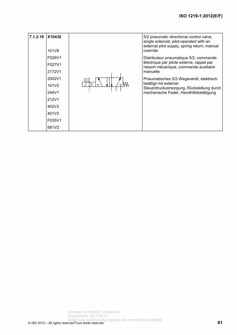
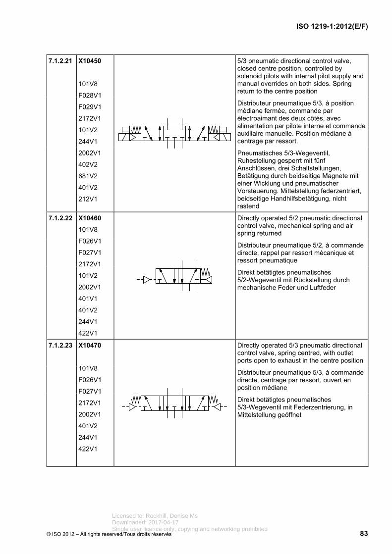
5/3 pneumatic directional control valve, closed centre position, controlled by solenoid pilots with internal pilot supply and manual overrides on both sides. Spring return to the centre position
Distributeur pneumatique 5/3, à position médiane fermée, commande par électroaimant des deux côtés, avec alimentation par pilote interne et commande auxiliaire manuelle. Position médiane à centrage par ressort.
Pneumatisches 5/3-Wegeventil, Ruhestellung gesperrt mit fünf Anschlüssen, drei Schaltstellungen, Betätigung durch beidseitige Magnete mit einer Wicklung und pneumatischer Vorsteuerung. Mittelstellung federzentriert, beidseitige Handhilfsbetätigung, nicht rastend
7.1.2.22 X10460
101V8
F026V1
F027V1
2172V1
101V2
2002V1
401V1
401V2
244V1
422V1
Directly operated 5/2 pneumatic directional control valve, mechanical spring and air spring returned
Distributeur pneumatique 5/2, à commande directe, rappel par ressort mécanique et ressort pneumatique
Direkt betätigtes pneumatisches 5/2-Wegeventil mit Rückstellung durch mechanische Feder und Luftfeder
7.1.2.23 X10470
101V8
F026V1
F027V1
2172V1
2002V1
401V2
244V1
422V1
Directly operated 5/3 pneumatic directional control valve, spring centred, with outlet ports open to exhaust in the centre position
Distributeur pneumatique 5/3, à commande directe, centrage par ressort, ouvert en position médiane
Direkt betätigtes pneumatisches 5/3-Wegeventil mit Federzentrierung, in Mittelstellung geöffnet
Licensed to: Rockhill, Denise MsDownloaded: 2017-04-17Single user licence only, copying and networking prohibited
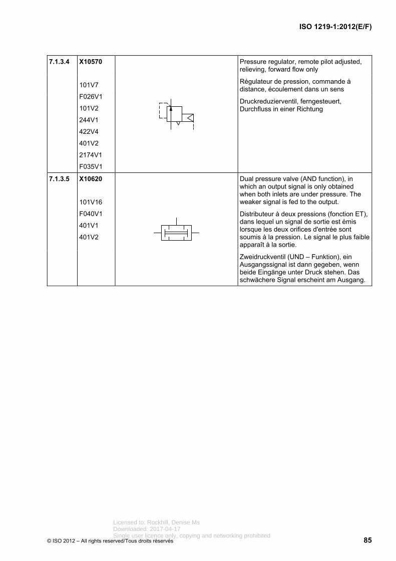
Pressure regulator, remote pilot adjusted, relieving, forward flow only
Régulateur de pression, commande à distance, écoulement dans un sens
Druckreduzierventil, ferngesteuert, Durchfluss in einer Richtung
7.1.3.5 X10620
101V16
F040V1
401V1
401V2
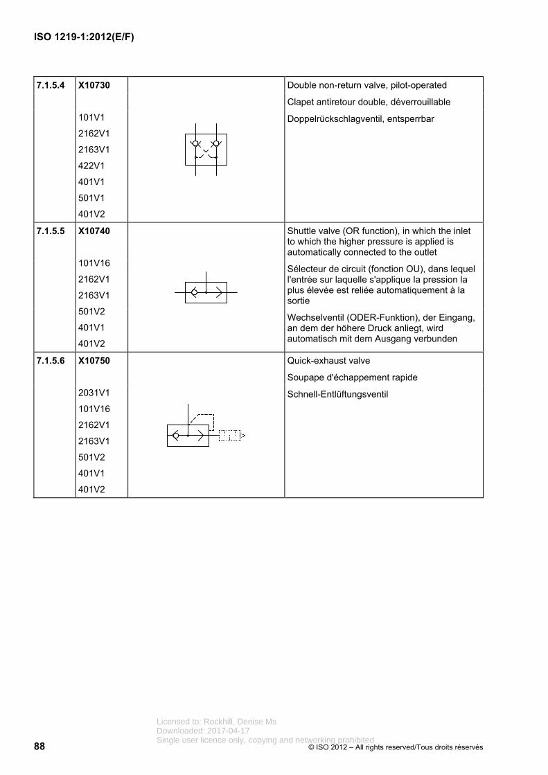
Dual pressure valve (AND function), in which an output signal is only obtained when both inlets are under pressure. The weaker signal is fed to the output.
Distributeur à deux pressions (fonction ET), dans lequel un signal de sortie est émis lorsque les deux orifices d'entrée sont soumis à la pression. Le signal le plus faible apparaît à la sortie.
Zweidruckventil (UND – Funktion), ein Ausgangssignal ist dann gegeben, wenn beide Eingänge unter Druck stehen. Das schwächere Signal erscheint am Ausgang.
Licensed to: Rockhill, Denise MsDownloaded: 2017-04-17Single user licence only, copying and networking prohibited
Doppeltwirkender Zylinder mit einseitiger Kolbenstange
7.3.3 X11460
101V13
101V14
F004V1
F004V2
101V19
201V7
401V2
Double-acting, double rod cylinder, with different piston rod diameters; cushioning on both sides with adjustment on right side only
Vérin à double effet, à double tige, de diamètres différents, avec amortissement de fin de course aux deux extrémités, réglable du côté droit
Doppeltwirkender Zylinder mit zweiseitiger Kolbenstange mit unterschiedlichen Durchmessern, beidseiter Endlagendämpfung auf der rechten Seite einstellbar
7.3.4 X11470
101V13
F006V1
F004V1
401V2
F020V1
203V1
Double-acting diaphragm cylinder with stroke limiter, preset
Vérin à diaphragme, à double effet, avec limiteur de course préréglé
Doppeltwirkender Membranzylinder mit Hubbegrenzung, voreingestellt
7.3.5 X11480
101V13
F004V1
F006V1
101V19
2002V3
2174V1
401V2
Single-acting diaphragm cylinder with cushioning on rod end; vented cap end
Vérin à diaphragme, à simple effet, avec amortissement de fin de course réglable d'un côté du piston, purge d'air sans possibilité de connexion
Einfachwirkender Membranzylinder mit Endlagendämpfung auf einer Kolbenseite, mit Entlüftung ohne Anschlussmöglichkeit
7.3.6 X11520
101V13
101V14
101V19
101V20
401V2
Double-acting band type rodless cylinder with end position cushioning on both sides of the piston
Vérin à double effet, sans tige, à ruban d'étanchéité, à amortissement de fin de course aux deux extrémités
Doppeltwirkender, kolbenstangenloser Dichtband-Zylinder mit beidseitiger Endlagendämpfung
Licensed to: Rockhill, Denise MsDownloaded: 2017-04-17Single user licence only, copying and networking prohibited
Double-acting cylinder, double rod, with internal limit switch on the left end, external limit switch on the right end, tripped by the piston rod
Vérin à double effet, à double tige, avec interrupteur de fin de course côté gauche, à commande mécanique interne, interrupteur de fin de course externe côté droit, à déclenchement par la tige
Doppeltwirkender Zylinder mit Endschalter auf der linken Seite, intern mechanisch betätigt, externer Endschalter auf der rechten Seite, ausgelöst durch die Kolbenstange
7.3.11 X11570
101V13
101V14
F004V1
661V1
101V2
244V1
401V1
401V2
Double-acting cylinder, mechanism for locking the piston rod and unlocking by pressurization
Vérin à double effet, verrouillage du piston et déverrouillage par application de pression
Doppeltwirkender Zylinder, Vorrichtung zum Blockieren des Kolbens und Lösen durch Druckbeaufschlagung
7.3.12 X11580
101V13
101V14
243V2
244V2
401V2
Pressure medium converter, single-acting, which converts a pneumatic pressure into a hydraulic pressure of the same value, or vice versa
Échangeur de pression air-huile, simple effet, qui sert à convertir une pression pneumatique en pression hydraulique de même valeur, ou inversement
Druckmittelwandler, einfachwirkend, der einen pneumatischen in einen hydraulischen Druck gleicher Höhe umwandelt, oder umgekehrt
7.3.13 X11590
F007V1
F008V1
243V2
244V2
401V2
Pressure intensifier, single-acting, which converts a pneumatic pressure p1 into a higher hydraulic pressure p2
Multiplicateur de pression, simple effet, qui sert à convertir une pression pneumatique p1 en une pression hydraulique p2 de valeur supérieure
Druckübersetzer, einfachwirkend, der einen pneumatischen Druck p1 in einen höheren hydraulischen Druck p2 umwandelt
Licensed to: Rockhill, Denise MsDownloaded: 2017-04-17Single user licence only, copying and networking prohibited
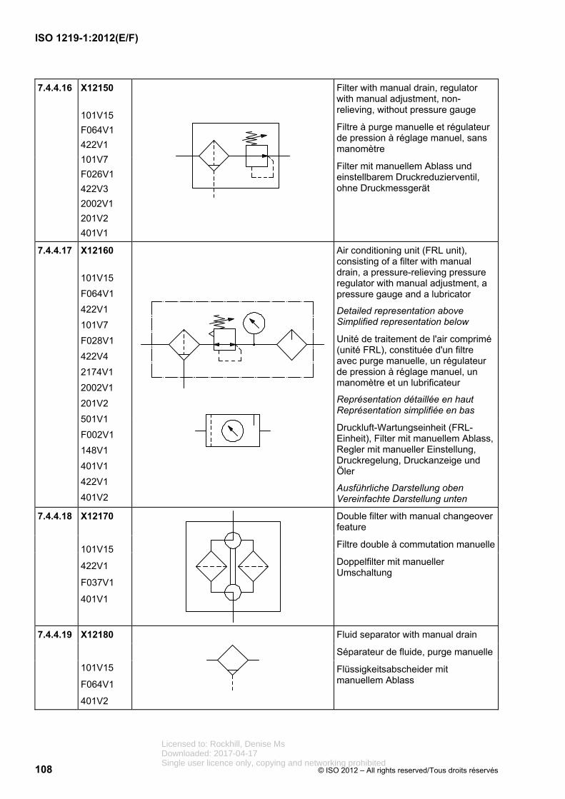
Filter with manual drain, regulator with manual adjustment, non-relieving, without pressure gauge
Filtre à purge manuelle et régulateur de pression à réglage manuel, sans manomètre
Filter mit manuellem Ablass und einstellbarem Druckreduzierventil, ohne Druckmessgerät
7.4.4.17 X12160
101V15
F064V1
422V1
101V7
F028V1
422V4
2174V1
2002V1
201V2
501V1
F002V1
148V1
401V1
422V1
401V2
Air conditioning unit (FRL unit), consisting of a filter with manual drain, a pressure-relieving pressure regulator with manual adjustment, a pressure gauge and a lubricator
Unité de traitement de l'air comprimé (unité FRL), constituée d'un filtre avec purge manuelle, un régulateur de pression à réglage manuel, un manomètre et un lubrificateur
Représentation détaillée en haut Représentation simplifiée en bas
Druckluft-Wartungseinheit (FRL-Einheit), Filter mit manuellem Ablass, Regler mit manueller Einstellung, Druckregelung, Druckanzeige und Öler
The centre line of the control mechanisms is drawn 1M above the lower edge of the rectangle/square.
Centre lines of additional control mechanisms, acting in parallel, are drawn at a 2M pitch. There should be no protrusion below the lower line of the functional element.
Les organes de commande sont dessinés centrés sur un axe positionné à une distance de 1M au-dessus du bord inférieur du rectangle/du carré.
Les axes des autres organes de commande à action parallèle sont dessinés à un écartement de 2M. Il convient que le bord inférieur de l'unité fonctionnelle ne dépasse pas en dessous.
Die Mittellinie des Betätigungselementes wird im Abstand von 1M zur Rechteck/Quadrat-Unterkante angeordnet.
Weitere parallel wirkende Elemente werden davon im Abstand 2M dargestellt. Die Unterkante des Funktionselements sollte nicht unterschritten werden.
Licensed to: Rockhill, Denise MsDownloaded: 2017-04-17Single user licence only, copying and networking prohibited
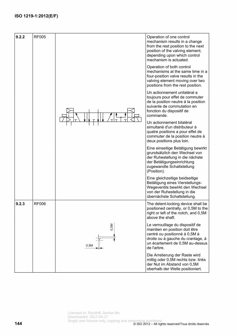
Operation of one control mechanism results in a change from the rest position to the next position of the valving element, depending upon which control mechanism is actuated.
Operation of both control mechanisms at the same time in a four-position valve results in the valving element moving over two positions from the rest position.
Un actionnement unilatéral a toujours pour effet de commuter de la position neutre à la position suivante de commutation en fonction du dispositif de commande.
Un actionnement bilatéral simultané d'un distributeur à quatre positions a pour effet de commuter de la position neutre à deux positions plus loin.
Eine einseitige Betätigung bewirkt grundsätzlich den Wechsel von der Ruhestellung in die nächste der Betätigungseinrichtung zugewandte Schaltstellung (Position).
Eine gleichzeitige beidseitige Betätigung eines Vierstellungs-Wegeventils bewirkt den Wechsel von der Ruhestellung in die übernächste Schaltstellung.
9.2.3 RF006
The detent-locking device shall be positioned centrally, or 0,5M to the right or left of the notch, and 0,5M above the shaft.
Le verrouillage du dispositif de maintien en position doit être centré ou positionné à 0,5M à droite ou à gauche du crantage, à un écartement de 0,5M au-dessus de l'arbre.
Die Arretierung der Raste wird mittig oder 0,5M rechts bzw. links der Nut im Abstand von 0,5M oberhalb der Welle positioniert.
Licensed to: Rockhill, Denise MsDownloaded: 2017-04-17Single user licence only, copying and networking prohibited
The detent grooves shall be positioned symmetrically on the shaft.
For more than three detent positions, the number of positions may be shown by placing the figure above the detent with a space of 0,5M .
Les dispositifs de maintien en position sont positionnés symétriquement à la liaison mécanique.
Si le nombre de crantages est supérieur à trois, il est possible d'indiquer le nombre de positions par un chiffre placé au-dessus de l'élément de crantage à un écartement de 0,5M.
Rasten sind symmetrisch auf der mechanischen Verbindung anzuordnen.
Bei mehr als drei Raststellungen kann die Anzahl der Stellungen als Zahl oberhalb des Rastelementes im Abstand von 0,5M angegeben werden.
9.2.5 RF008
If necessary, a switch position without detent should be shown.
Il convient de représenter, si nécessaire, une position sans possibilité de crantage.
Falls erforderlich, ist eine nicht rastbare Schaltstellung darzustellen.
Licensed to: Rockhill, Denise MsDownloaded: 2017-04-17Single user licence only, copying and networking prohibited
Control mechanisms shall be drawn directly on the corresponding rectangle/square.
Les organes de commande doivent être directement dessinés sur le rectangle/le carré correspondant.
Betätigungselemente müssen direkt an das entsprechende Rechteck/Quadrat gezeichnet werden.
9.2.7 RF010
Control mechanisms shall be drawn on the right side of the rectangle/square unless they are represented on both sides.
Les organes de commande doivent être représentés sur le côté droit du carré/du rectangle, sauf s'ils existent des deux côtés.
Betätigungselemente werden, wenn nicht beidseitig vorhanden, auf der rechten Seite des Quadrats/Rechtecks dargestellt.
9.2.8 RF011
If the size of the symbol is insufficient to accommodate the control mechanisms, an extension line is drawn. This can be done on both sides of the functional element.
Si le côté d'un symbole ne suffit pas pour positionner les organes de commande, tracer une ligne verticale de jonction, éventuellement de part et d'autre de l'élément fonctionnel.
Reicht die Seite eines Symbols zur Positionierung der Betätigungselemente nicht aus, wird eine Verbindungslinie hochgezogen. Dies kann auch beidseitig des Betätigungselementes erfolgen.
Licensed to: Rockhill, Denise MsDownloaded: 2017-04-17Single user licence only, copying and networking prohibited
Control mechanisms and signal converters acting in parallel shall be arranged from bottom to top in the following order:
hydraulic/pneumatic
solenoid
spring
manual control element
converter
If identical control mechanisms are located on both sides of the functional element, their order must be located symmetrically. Overlapping of the symbols is not permitted.
Les organes de commande et les convertisseurs de signaux à action parallèle doivent être disposés de bas en haut dans l'ordre suivant:
hydraulique/pneumatique
électroaimant
ressort
commande manuelle
convertisseur
Lorsque des organes de commande identiques sont fournis des deux côtés de l'élément fonctionnel, ils doivent être représentés symétriquement. Le chevauchement des symboles n'est pas permis.
Parallel wirkende Betätigungs-elemente und Signalwandler werden von unten nach oben angeordnet und zwar in der Reihenfolge
hydraulisch/pneumatisch
Magnet
Feder
Handbetätigung
Wandler
Sind Betätigungselemente paarig vorhanden, müssen diese sym-metrisch dargestellt werden. Lücken sind nicht aufzufüllen. Grafische Überlagerungen von Betätigungselementen sind unzulässig.
Licensed to: Rockhill, Denise MsDownloaded: 2017-04-17Single user licence only, copying and networking prohibited
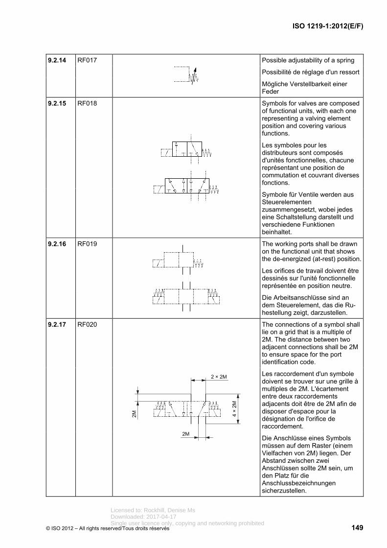
Symbols for valves are composed of functional units, with each one representing a valving element position and covering various functions.
Les symboles pour les distributeurs sont composés d'unités fonctionnelles, chacune représentant une position de commutation et couvrant diverses fonctions.
Symbole für Ventile werden aus Steuerelementen zusammengesetzt, wobei jedes eine Schaltstellung darstellt und verschiedene Funktionen beinhaltet.
9.2.16 RF019
The working ports shall be drawn on the functional unit that shows the de-energized (at-rest) position.
Les orifices de travail doivent être dessinés sur l'unité fonctionnelle représentée en position neutre.
Die Arbeitsanschlüsse sind an dem Steuerelement, das die Ru-hestellung zeigt, darzustellen.
9.2.17 RF020
The connections of a symbol shall lie on a grid that is a multiple of 2M. The distance between two adjacent connections shall be 2M to ensure space for the port identification code.
Les raccordement d'un symbole doivent se trouver sur une grille à multiples de 2M. L'écartement entre deux raccordements adjacents doit être de 2M afin de disposer d'espace pour la désignation de l'orifice de raccordement.
Die Anschlüsse eines Symbols müssen auf dem Raster (einem Vielfachen von 2M) liegen. Der Abstand zwischen zwei Anschlüssen sollte 2M sein, um den Platz für die Anschlussbezeichnungen sicherzustellen.
Licensed to: Rockhill, Denise MsDownloaded: 2017-04-17Single user licence only, copying and networking prohibited
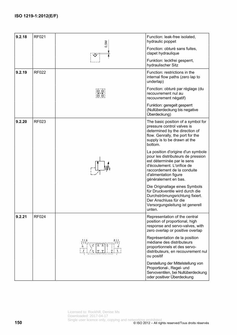
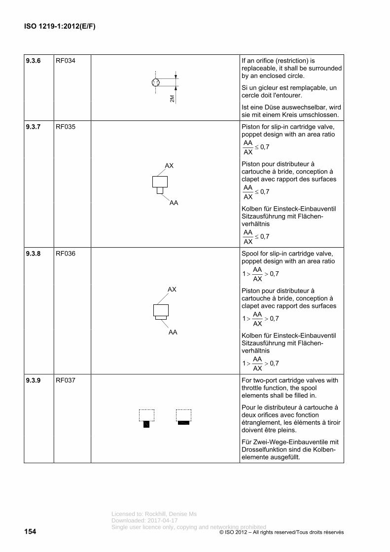
Function: restrictions in the internal flow paths (zero lap to underlap)
Fonction: obturé par réglage (du recouvrement nul au recouvrement négatif)
Funktion: geregelt gesperrt (Nullüberdeckung bis negative Überdeckung)
9.2.20 RF023
The basic position of a symbol for pressure control valves is determined by the direction of flow. Genrally, the port for the supply is to be drawn at the bottom.
La position d'origine d'un symbole pour les distributeurs de pression est déterminée par le sens d'écoulement. L'orifice de raccordement de la conduite d'alimentation figure généralement en bas.
Die Originallage eines Symbols für Druckventile wird durch die Durchströmungsrichtung fixiert. Der Anschluss für die Versorgungsleitung ist generell unten.
9.2.21 RF024
Representation of the central position of proportional, high response and servo-valves, with zero overlap or positive overlap
Représentation de la position médiane des distributeurs proportionnels et des servo-distributeurs, en recouvrement nul ou positif
Darstellung der Mittelstellung von Proportional-, Regel- und Servoventilen, bei Nullüberdeckung oder positiver Überdeckung
Licensed to: Rockhill, Denise MsDownloaded: 2017-04-17Single user licence only, copying and networking prohibited
Valves with two or more working positions and an optional number of intermediate positions with different throttling effects shall be drawn with two parallel lines along the symbol.
Les distributeurs avec au moins deux positions d'utilisation et un certain nombre de positions intermédiaires ayant des effets d'étranglement différents doivent être représentés par deux traits parallèles le long du symbole.
Ventile mit zwei oder mehreren Arbeitsstellungen und einer beliebigen Anzahl von Zwischenstellungen mit unter-schiedlicher Drosselwirkung werden durch zwei Parallellinien entlang des Symbols dargestellt.
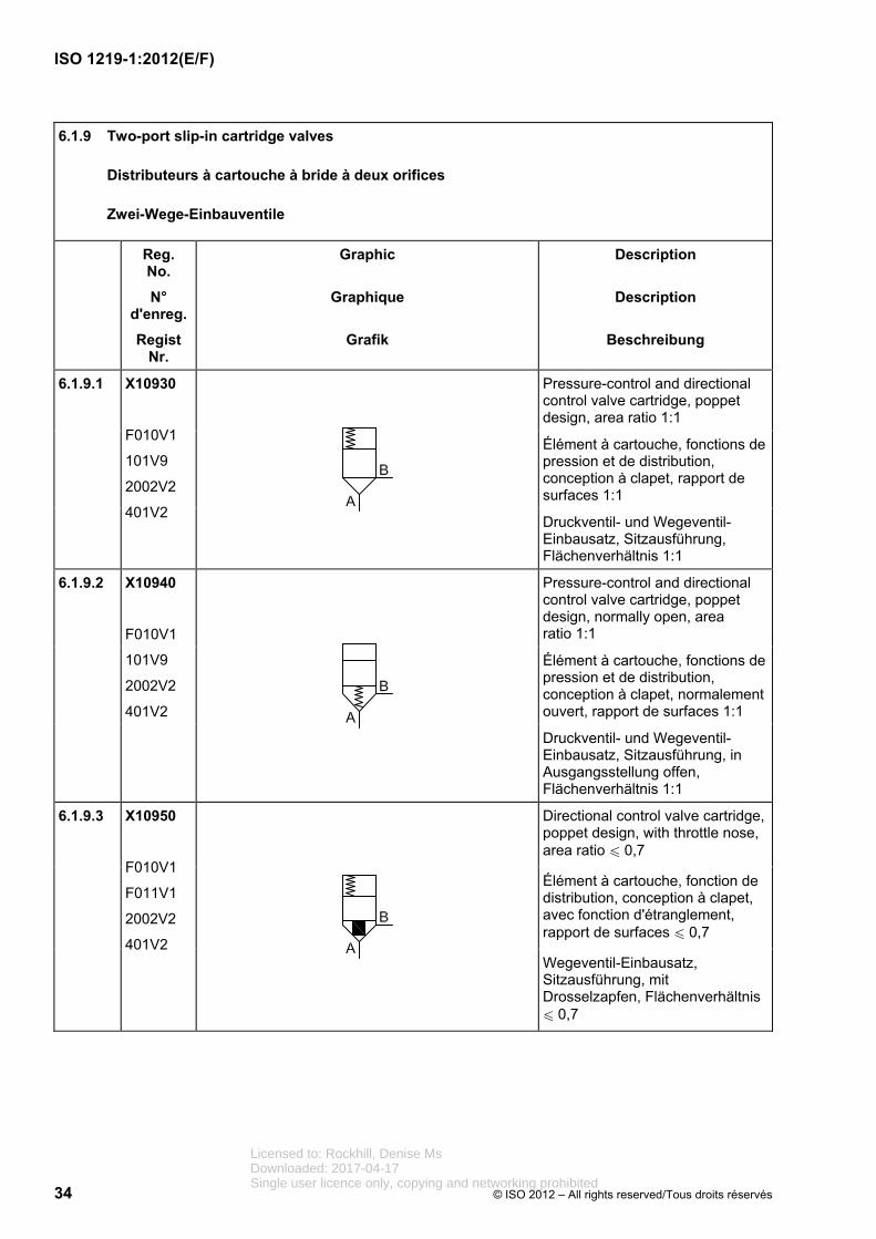
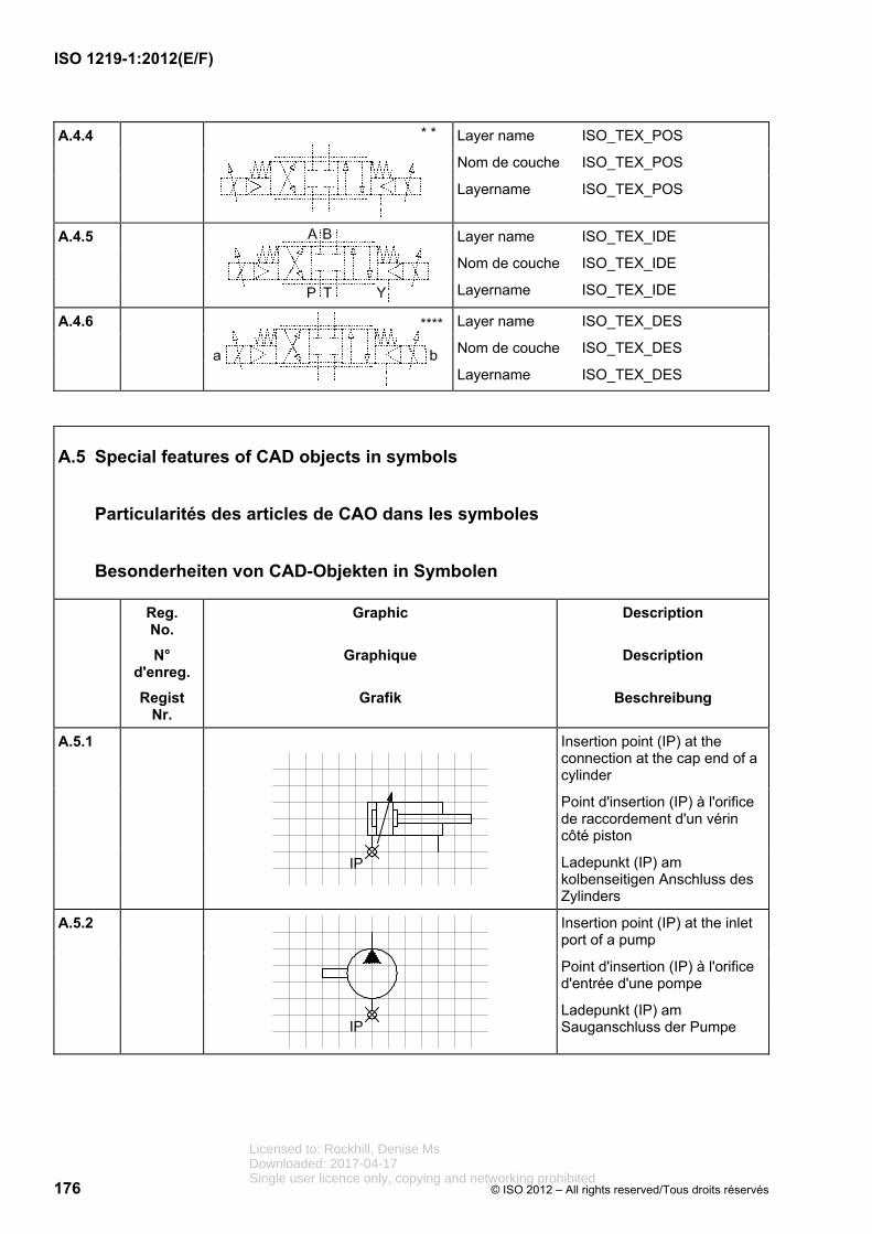
9.3 Two-port slip-in cartridge valves
Distributeurs à cartouche à bride à deux orifices
Zwei-Wege-Einbauventile
Reg. No.
N° d'enreg.
Regist Nr.
Graphic
Graphique
Grafik
Description
Description
Beschreibung
9.3.1 RF029
A symbol for a two-port cartridge valve consists of two elements: the control cover and the cartridge. The cartridge and/or control cover can include further basic elements or symbols.
Le symbole du distributeur à cartouche à deux voies est constitué de deux éléments: le couvercle de pilotage et la cartouche. La cartouche et/ou le couvercle de pilotage peuvent comporter d'autres éléments ou symboles de base.
Das Symbol eines Zwei-Wege-Einbauventiles besteht aus zwei Elementen, dem Steuerdeckel und dem Einbausatz. Einbausatz und/oder Steuerdeckel können weitere Grundelemente oder Symbole enthalten.
Licensed to: Rockhill, Denise MsDownloaded: 2017-04-17Single user licence only, copying and networking prohibited
The connections of a control cover shall be located on the frame on grid points. Their position is fixed.
Les orifices de raccordement du couvercle de pilotage doivent se trouver sur des points de grille sur l'encadrement. Leur position a une définition fixe.
Die Anschlüsse eines Steuer-deckels befinden sich auf der Umrahmung auf Rasterpunkten. Ihre Lage ist fest definiert.
9.3.3 RF031
External connections shall be drawn on the sides.
Les orifices de raccordement externes doivent ête placés sur les côtés.
Externe Anschlüsse sind an den Seiten anzubringen.
9.3.4 RF032
The working ports are located at the bottom and at the sides of the symbol.
The A-port is shown at the bottom, the B-port may be shown on the right-hand side, on the left-hand side or on both sides.
Les orifices de raccordement des récepteurs sont dessinés en bas et sur les côtés du symbole.
L'orifice A est représenté en bas, l'orifice B peut être représenté sur le côté droit, sur le côté gauche ou des deux côtés.
Die Verbraucheranschlüsse werden unten und seitlich angeordnet.
Der A-Anschluss ist unten dargestellt, der B-Anschluss ist entweder an der rechten Seite, an der linken Seite oder an beiden Seiten angeordnet.
9.3.5 RF033
The opening pressure of the valve shall be indicated next to the symbol (**).
La pression d'ouverture doit être indiquée à côté du symbole (**).
Der Öffnungsdruck wird neben dem Symbol dargestellt (**).
Licensed to: Rockhill, Denise MsDownloaded: 2017-04-17Single user licence only, copying and networking prohibited
The drive shaft of a pump is positioned on the left-hand side (preferred position) or on the right-hand side and may be extended in multiples of 2M.
L'arbre d'une pompe est indiqué vers la gauche (de préférence) ou vers la droite et peut être prolongé par des écartements de 2M.
Die Welle der Pumpe zeigt nach links (vorzugsweise) oder nach rechts und kann im Abstand von 2M verlängert werden.
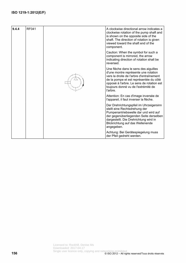
9.4.2 RF039
The shaft of a motor is positioned on the right-hand side (preferred position) or on the left-hand side.
L'arbre d'un moteur est indiqué vers la droite (de préférence) ou vers la gauche.
Die Welle eines Motors zeigt nach rechts (vorzugsweise) oder nach links.
9.4.3 RF040
The arrow that indicates adjustability shall be placed on the diameter of the symbol of the energy conversion unit. If required, it can be made longer.
La flèche de réglage doit être placée sur un diamètre du symbole concerné. Si nécessaire, elle peut être prolongée.
Der Verstellpfeil muss mittig im Symbol platziert werden. Bei Bedarf kann er verlängert werden.
Licensed to: Rockhill, Denise MsDownloaded: 2017-04-17Single user licence only, copying and networking prohibited
A clockwise directional arrow indicates a clockwise rotation of the pump shaft and is shown on the opposite side of the shaft. The direction of rotation is given viewed toward the shaft end of the component.
Caution: When the symbol for such a component is mirrored, the arrow indicating direction of rotation shall be reversed.
Une flèche dans le sens des aiguilles d'une montre représente une rotation vers la droite de l'arbre d'entraînement de la pompe et est représentée du côté opposé à l'arbre. Le sens de rotation est toujours donné vu de l'extrémité de l'arbre.
Attention: En cas d'image inversée de l'appareil, il faut inverser la flèche.
Der Drehrichtungspfeil im Uhrzeigersinn stellt eine Rechtsdrehung der Pumpenantriebswelle dar und wird auf der gegenüberliegenden Seite derselben dargestellt. Die Drehrichtung wird in Blickrichtung auf das Wellenende angegeben.
Achtung: Bei Gerätespiegelung muss der Pfeil gedreht werden.
Licensed to: Rockhill, Denise MsDownloaded: 2017-04-17Single user licence only, copying and networking prohibited
A counter-clockwise directional arrow indicates a counter-clockwise rotation of the pump shaft and is shown on the opposite side of the connection shaft. The direction of rotation is given viewed toward the shaft end of the component.
Caution: When the symbol for such a component is mirrored, the arrow indicating direction of rotation shall be reversed.
Une flèche dans le sens inverse des aiguilles d'une montre représente une rotation vers la gauche de l'arbre d'entraînement de la pompe et est représentée du côté opposé à l'arbre. Le sens de rotation est toujours donné vu de l'extrémité de l'arbre.
Attention: En cas d'image inversée de l'appareil, il faut inverser la flèche.
Der Drehrichtungspfeil im Gegenuhrzeigersinn stellt eine Linksdrehung der Pumpenantriebswelle dar und wird auf der gegenüberliegenden Seite derselben dargestellt. Die Drehrichtung wird in Blickrichtung auf das Wellenende angegeben.
Achtung: Bei Gerätespiegelung muss der Pfeil gedreht werden.
9.4.6 RF043
The drain line of a pump or a motor is represented at an angle of less than 45 ° to the bottom right between the axis of displacement and the drive axis.
La conduite de fuite d'une pompe ou d'un moteur est représentée à un angle inférieur à 45° en bas à droite entre l'axe de cylindrée et l'axe d'entraînement.
Die Leckölleitung einer Pumpe oder eines Motors wird unter 45 Grad nach unten rechts zwischen der Förder-stromachse und der Antriebsachse gebildet.
Licensed to: Rockhill, Denise MsDownloaded: 2017-04-17Single user licence only, copying and networking prohibited
The piston shall be represented 1M away from the cylinder cap end. Lines that connect to the ports shall be 0,5M away from the end of the cylinder frame.
Le piston est représenté à un écartement de 1M du fond du vérin. L'orifice de raccordement de la conduite se trouve à un écartement 0,5M de l'extrémité du tube de vérin.
Der Kolben wird 1M vom Zylinderboden entfernt dargestellt. Der Leitungs-anschluss endet 0,5M vom Zylinderrohr.
9.5.2 RF045
The cylinder frame shall be open to accommodate the piston rod symbol element.
Le contour du vérin doit être ouvert selon le diamètre de la tige de vérin.
Die Zylinderkontur ist entsprechend der Kolbenstangendurchmesser zu öffnen.
9.5.3 RF046
The stroke limiter shall be shown on the cap end.
Le limiteur de course doit être représenté côté opposé à la tige du piston.
Die Hubbegrenzung wird gegenüber der Kolbenstangenseite dargestellt.
Licensed to: Rockhill, Denise MsDownloaded: 2017-04-17Single user licence only, copying and networking prohibited
Mechanical limiters shall be represented in a symmetrical manner.
Les limitations mécaniques doivent être représentées en disposition symétrique.
Mechanische Begrenzungen werden symmetrisch angeordnet dargestellt.
9.5.5 RF048
The possiblity of adjustment shall be indicated by drawing the arrow through the adjustable element. The possibility of the adjustment of two elements shall be shown at the centre of the distance between the adjustable elements.
La possibilité de réglage doit être représentée par une flèche à travers l'élément de réglage. Une possibilité de réglage de deux éléments est représentée au milieu entre les deux éléments de réglage.
Eine mögliche Verstellbarkeit ist mit einem Pfeil durch das Verstellelement darzustellen. Eine mögliche Verstellbarkeit zweier Elemente ist mittig zwischen beiden Verstellelementen darzustellen.
Licensed to: Rockhill, Denise MsDownloaded: 2017-04-17Single user licence only, copying and networking prohibited
The ports of a multiple-way rotary connection are drawn at a spacing of 2M at both sides of the connection. Their number is user-defined and expandable. The designations of ports are shown above the port symbol.
The aggregation of the flow paths shall be drawn centred.
Les raccordements d'un passage tournant à voies multiples sont représentés à un intervalle de 2M de part et d'autre de la connexion. Leur nombre est défini par l'utilisateur et peut être étendu. La désignation des orifices figure au-dessus des raccordements.
Le faisceau de connexions est représenté centré.
Die Anschlüsse einer Mehrwege-Drehdurchführung werden im Abstand von 2M beiderseits der Verbindung dargestellt. Ihre Anzahl ist beliebig erweiterbar. Die Leitungsbezeichnungen stehen oberhalb der Anschlüsse.
Die Verbindungszusammenfassung ist mittig darzustellen.
9.6.1.2 RF050
The connection of two lines is shown by means of a connection point.
La connexion de deux conduites est représentée par un point de connexion.
Die Verbindung zweier Leitungen wird mittels Verbindungspunkt dargestellt.
Licensed to: Rockhill, Denise MsDownloaded: 2017-04-17Single user licence only, copying and networking prohibited
Versorgungsanschluss 14 pilot port/orifice de pilotage/
Steueranschluss
Enough space for indicating the port designations shall be provided above or to the left of each port. The examples for lettering/numbering the ports are in accordance with ISO 9461 for hydraulics and ISO 11727 for pneumatics.
Des cases libres de désignation des orifices de raccordement doivent être prévues au-dessus ou à gauche de chaque connexion. Les exemples de désignation (lettres ou chiffres) des orifices sont conformes à l'ISO 9461 pour l'hydraulique et à l'ISO 11727 pour la pneumatique.
Platzhalter zur Anschlussbezeichnung sind oberhalb oder links neben den Anschlüssen vorzusehen. Die Beispiele für die Anschlussbezeichnungen entsprechen ISO 9461 für Hydraulik und ISO 11727 für Pneumatik.
Licensed to: Rockhill, Denise MsDownloaded: 2017-04-17Single user licence only, copying and networking prohibited
More than one contact can be drawn in the same frame. Each can have a different function (break contact, make contact, switch contact).
If there are more than three contacts, the number of contacts may be shown as a numeral positioned 0,5M above the contact within the frame.
Plusieurs contacts peuvent être dessinés dans un même cadre. Ils peuvent avoir des effets différents (contact d'ouverture, de fermeture, inverseur).
Si leur nombre est supérieur à trois, ce nombre peut être indiqué par un chiffre en dessus du contact à un écartement de 0,5M à l'intérieur du cadre.
Mehrere Kontakte werden in einem Rahmen dargestellt. Diese können unterschiedliche Wirkungsweise haben (Öffner, Schließer, Wechsler).
Bei mehr als 3 gleichen Kontakten kann die Anzahl der Kontakte als Zahl oberhalb des Kontaktes im Abstand von 0,5M innerhalb des Rahmens angegeben werden.
9.6.3 Measuring instruments and indicators
Appareils de mesurage et indicateurs
Mess- und Anzeigegeräte
Reg. No.
N° d'enreg.
Regist Nr.
Graphic
Graphique
Grafik
Description
Description
Beschreibung
9.6.3.1 RF058
Position of arrow and asterisk for display units
* Position for details
Position de la flèche et de l'astérisque pour les indicateurs
* Espace destiné à de plus amples détails
Position von Pfeil und Stern für Anzeigegeräte
* Platz für nähere Angaben
Licensed to: Rockhill, Denise MsDownloaded: 2017-04-17Single user licence only, copying and networking prohibited
Segment 2 comprises three characters (three-character block) that are derived from the initial letters of the English words for the objects.
EXAMPLE LINE = LIN TEXT = TEX
Segment 3 represents further features of the object and is made up of individual elements. It can be composed of several three-letter blocks, which are to be connected with an underline.
Segment 1 définit l'origine de l'article.
Segment 2 contient une suite de trois caractères (blocs de trois caractères séparés) dérivés des premières lettres du terme anglais de l'article.
EXEMPLE LINE = LIN TEXT = TEX
Segment 3 contient d'autres caractéristiques de l'article, est formé à partir d'éléments individuels. Il peut se composer de plusieurs blocs de trois lettres séparés par un trait souligné.
Segment 1 legt die Herkunft des Objektes fest.
Segment 2 ist eine Folge von drei Buchstaben (Dreierblock), die aus den Anfangsbuchstaben der englischen Worte des Objektes abgeleitet werden.
BEISPIEL LINE = LIN TEXT = TEX
Segment 3 stellt weitere Merkmale des Objektes dar und wird aus einzelnen Elementen gebildet. Es kann aus mehreren Dreierblöcken, die mit Unterstrich verbunden sind, zusammengesetzt werden.
A.1.2
Insertion points (IP) are always positioned at the fluid supply line.
Les points d'insertion (IP) se trouvent toujours sur la conduite d'alimentation du fluide.
Ladepunkte (IP) sind immer an der Fluidversorgungsleitung positioniert.
Licensed to: Rockhill, Denise MsDownloaded: 2017-04-17Single user licence only, copying and networking prohibited
[1] ISO 1219-2, Fluid power systems andcomponents — Graphical symbols and circuit diagrams — Part 2: Circuit diagrams
[1] ISO 1219-2, Transmissions hydrauliques et pneumatiques — Symboles graphiques et schémas de circuit — Partie 2: Schémas de circuit
[2] ISO 3511-2, Process measurement controlfunctions and instrumentation — Symbolicrepresentation — Part 2: Extension of basicrequirements
[2] ISO 3511-2, Fonctions et instrumentation pour la mesure et la régulation des processus industriels — Représentation symbolique —Partie 2: Extension des principes de base
[3] ISO 3511-3, Process measurement controlfunctions and instrumentation — Symbolicrepresentation — Part 3: Detailed symbols forinstrument interconnection diagrams
[3] ISO 3511-3, Fonctions et instrumentation pour la mesure et la régulation des processus industriels — Représentation symbolique —Partie 3: Symboles détaillés pour les diagrammes d'interconnexion d'instruments
[4] ISO 9461, Hydraulic fluid power —Identification of valve ports, subplates, controldevices and solenoids
[4] ISO 9461, Transmissions hydrauliques —Identification des orifices des appareils, embases, organes de commande et solénoïdes
[5] ISO 11727, Pneumatic fluid power —Identification of ports and control mechanismsof control valves and other components
[5] ISO 11727, Transmissions pneumatiques —Identification des orifices et des mécanismes de commande des distributeurs de commande et autres composants
Licensed to: Rockhill, Denise MsDownloaded: 2017-04-17Single user licence only, copying and networking prohibited
Licensed to: Rockhill, Denise MsDownloaded: 2017-04-17Single user licence only, copying and networking prohibited
ISO 1219-1:2012(E/F)
ICS 01.080.30; 23.100.01 Price based on 178 pages/Prix basé sur 178 pages