An anisotropic tertiary creep damage constitutive model for anisotropic materials Calvin M. Stewart a, * , Ali P. Gordon a , Young Wha Ma b , Richard W. Neu c a Department of Mechanical, Materials, & Aerospace Engineering, University of Central Florida, USA b Department of Mechanical Engineering, Chung Ang University, 221 Huksuk Dongjak, Seoul 156-756, Republic of Korea c George W. Woodruff School of Mechanical Engineering, Georgia Institute of Technology, Atlanta, GA 30332-0405, USA article info Article history: Received 20 April 2010 Received in revised form 30 June 2011 Accepted 30 June 2011 Keywords: Transversely-isotropic Continuum damage mechanics (CDM) Directionally-solidified Ni-base superalloy Void induced anisotropy Multiaxial abstract When an anisotropic material is subject to creep conditions and a complex state of stress, an anisotropic creep damage behavior is observed. Previous research has focused on the anisotropic creep damage behavior of isotropic materials but few constitutive models have been developed for anisotropic creeping solids. This paper describes the development of a new anisotropic tertiary creep damage constitutive model for anisotropic materials. An advanced tensorial damage formulation is implemented which includes both material orientation relative to loading and the degree of creep damage anisotropy in the model. A variation of the Norton-power law for secondary creep is implemented which includes the Hill’s anisotropic analogy. Experiments are conducted on the directionally-solidified bucket material DS GTD- 111. The constitutive model is implemented in a user programmable feature (UPF) in ANSYS FEA soft- ware. The ability of the constitutive model to regress to the Kachanov-Rabotnov isotropic tertiary creep damage model is demonstrated through comparison with uniaxial experiments. A parametric study of both material orientation and stress rotation are conducted. Results indicate that creep deformation is modeled accurately; however an improved damage evolution law may be necessary. Ó 2011 Elsevier Ltd. All rights reserved. 1. Introduction In the power generation and aerospace industries, components such as pressure vessels, pipes, gas turbine disks and vanes, and turbine blades experience high temperatures such that creep deformation will occur. In the case of industrial gas turbines where the cycle duration and maintenance intervals can be in the thou- sands of hours, and there are drives to increases temperature and pressure, careful selection and accurate prediction of material behavior is paramount; therefore, directionally-solidified (DS) materials have been implemented to minimize intergranular (brittle) creep cracking by alignment of long grains with the first principal stress direction [1]. Typically DS gas turbine blade mate- rials are transversely-isotropic, consisting of a columnar micro- structure where there is a plane of “transverse grain (T)” isotropy and an enhanced “longitudinal grain (L)” orientation. Creep and stress-rupture properties are one of the more important variables in the overall life of turbine blades [2]. In the case of welded pressure vessels, welding is a directional solidification process. A single weld bead consists of a single columnar solidification microstructure. Multi-pass welding (used on pressure vessels) will produce a transversely-isotropic microstruc- ture [3]. In the case of thin-walled pipes used in power plants, consid- erable work has been focused around isotropic creep damage modeling [4,5]. Literature has demonstrated that strength anisot- ropy in thin-walled tubular elements is common [6]. Accurate, modeling of the creep deformation and damage behavior of transversely-isotropic materials is important. A novel anisotropic creep damage model for transversely-isotropic materials is developed based on the Kachanov-Rabotnov isotropic formulation [7,8]. Experiments are conducted on uniaxial specimen of the bucket material DS GTD-111. The constitutive model is implemented in Finite Element Analysis (FEA) software. A comparison between the experiments, Kachanov-Rabotnov model, and novel constitutive model is conducted. An examination of the strain tensor is provided. A parametric exercise of the constitutive model for various material orientations and states of stress demonstrates functionality. 2. Continuum damage mechanics A damage mechanism is a manifestation of the degradation of the microstructure of a material and can occur in two forms: transgranular (ductile) damage and intergranular (brittle) damage. Transgranular (ductile) damage arises where slip bands of plasticity * Corresponding author. 4000 Central Florida Blvd., Bldg. 40 Room 358, Orlando, FL 32816-2450, USA. Tel.: þ1 (407) 435 0047. E-mail address: [email protected](C.M. Stewart). Contents lists available at ScienceDirect International Journal of Pressure Vessels and Piping journal homepage: www.elsevier.com/locate/ijpvp 0308-0161/$ e see front matter Ó 2011 Elsevier Ltd. All rights reserved. doi:10.1016/j.ijpvp.2011.06.010 International Journal of Pressure Vessels and Piping 88 (2011) 356e364
Transcript
lable at ScienceDirect
International Journal of Pressure Vessels and Piping 88 (2011) 356e364
Contents lists avai
International Journal of Pressure Vessels and Piping
journal homepage: www.elsevier .com/locate/ i jpvp
An anisotropic tertiary creep damage constitutive model for anisotropic materials
Calvin M. Stewart a,*, Ali P. Gordon a, Young Wha Ma b, Richard W. Neu c
aDepartment of Mechanical, Materials, & Aerospace Engineering, University of Central Florida, USAbDepartment of Mechanical Engineering, Chung Ang University, 221 Huksuk Dongjak, Seoul 156-756, Republic of KoreacGeorge W. Woodruff School of Mechanical Engineering, Georgia Institute of Technology, Atlanta, GA 30332-0405, USA
a r t i c l e i n f o
Article history:Received 20 April 2010Received in revised form30 June 2011Accepted 30 June 2011
0308-0161/$ e see front matter � 2011 Elsevier Ltd.doi:10.1016/j.ijpvp.2011.06.010
a b s t r a c t
When an anisotropic material is subject to creep conditions and a complex state of stress, an anisotropiccreep damage behavior is observed. Previous research has focused on the anisotropic creep damagebehavior of isotropic materials but few constitutive models have been developed for anisotropic creepingsolids. This paper describes the development of a new anisotropic tertiary creep damage constitutivemodel for anisotropic materials. An advanced tensorial damage formulation is implemented whichincludes both material orientation relative to loading and the degree of creep damage anisotropy in themodel. A variation of the Norton-power law for secondary creep is implemented which includes the Hill’sanisotropic analogy. Experiments are conducted on the directionally-solidified bucket material DS GTD-111. The constitutive model is implemented in a user programmable feature (UPF) in ANSYS FEA soft-ware. The ability of the constitutive model to regress to the Kachanov-Rabotnov isotropic tertiary creepdamage model is demonstrated through comparison with uniaxial experiments. A parametric study ofboth material orientation and stress rotation are conducted. Results indicate that creep deformation ismodeled accurately; however an improved damage evolution law may be necessary.
� 2011 Elsevier Ltd. All rights reserved.
1. Introduction
In the power generation and aerospace industries, componentssuch as pressure vessels, pipes, gas turbine disks and vanes, andturbine blades experience high temperatures such that creepdeformation will occur. In the case of industrial gas turbines wherethe cycle duration and maintenance intervals can be in the thou-sands of hours, and there are drives to increases temperature andpressure, careful selection and accurate prediction of materialbehavior is paramount; therefore, directionally-solidified (DS)materials have been implemented to minimize intergranular(brittle) creep cracking by alignment of long grains with the firstprincipal stress direction [1]. Typically DS gas turbine blade mate-rials are transversely-isotropic, consisting of a columnar micro-structure where there is a plane of “transverse grain (T)” isotropyand an enhanced “longitudinal grain (L)” orientation. Creep andstress-rupture properties are one of the more important variablesin the overall life of turbine blades [2].
In the case of welded pressure vessels, welding is a directionalsolidification process. A single weld bead consists of a single
Bldg. 40 Room 358, Orlando,
.M. Stewart).
All rights reserved.
columnar solidification microstructure. Multi-pass welding (used onpressure vessels) will produce a transversely-isotropic microstruc-ture [3].
In the case of thin-walled pipes used in power plants, consid-erable work has been focused around isotropic creep damagemodeling [4,5]. Literature has demonstrated that strength anisot-ropy in thin-walled tubular elements is common [6].
Accurate, modeling of the creep deformation and damagebehavior of transversely-isotropic materials is important. A novelanisotropic creep damage model for transversely-isotropic materialsis developed based on the Kachanov-Rabotnov isotropic formulation[7,8]. Experiments are conducted on uniaxial specimen of the bucketmaterial DS GTD-111. The constitutive model is implemented inFinite Element Analysis (FEA) software. A comparison between theexperiments, Kachanov-Rabotnov model, and novel constitutivemodel is conducted. An examination of the strain tensor is provided.A parametric exercise of the constitutive model for various materialorientations and states of stress demonstrates functionality.
2. Continuum damage mechanics
A damage mechanism is a manifestation of the degradation ofthe microstructure of a material and can occur in two forms:transgranular (ductile) damage and intergranular (brittle) damage.Transgranular (ductile) damage arises where slip bands of plasticity
C.M. Stewart et al. / International Journal of Pressure Vessels and Piping 88 (2011) 356e364 357
form under high stress and low temperature. Intergranular (brittle)damage is a microcracking process at grain boundaries under hightemperature and low stress [9]. A number of Continuum DamageMechanics (CDM) based constitutive models have been developedfor creep damage prediction [10]. An early and often cited attemptcame from Kachanov [7] and Rabotnov [8] in the form of coupledcreep strain rate and damage evolution equations for isotropicmaterials as follows
_ecr ¼ decrdt
¼ A� s
1� u
�n(1)
_u ¼ dudt
¼ Msc
ð1� uÞf(2)
where A and n are secondary creep constants, M, c, and f aretertiary creep damage constants, and _ecr and s are the equivalentcreep strain and von Mises stress respectively [11e13]. Thisisotropic formulation regards damage as a scalar state variable, uthat accounts for all microstructural degradations exhibited ina material. Numerous specialized variations on this isotropicconstitutive model can be found throughout literature [14e20]. Theconstitutive model has also been generalized for multiaxial statesof stress in isotropic materials using elastic compliance tensors andthe stress deviator [21].
Literature shows that under creep conditions, intergranulardamage must be represented by multiple principal damage vari-ables. Damage can induce an anisotropic creep response [5,22].Literature shows that damage anisotropy can be indentified in twomaterial classes, aluminum-like and copper-like [9,23]. Foraluminum-like materials, damage is typically distributed iso-tropically. Aluminum-like materials with a simple stress state (i.e.,uniaxial creep tests) can be modeled with isotropic creep damagemodels [22e25]. For copper-like materials, damage developsmainly on the plane perpendicular to the first principal stress.Copper-like materials and components undergoing a complexstate of stress exhibit damage induced anisotropic creep responsewhich must be accounted for with more robust modeling tech-niques [26]. Models have been developed that can account forboth aluminum-like and copper-like materials, and the range ofintermediate behaviors between them [5,27]. These isotropicconstitutive models are unable to model anisotropic microstruc-ture materials.
A number of researchers have developed constitutivemodels fortransversely-isotropic materials; however, most formulations donot accurately model intermediate material orientations (when thelongitudinal grains are not parallel or perpendicular to the loaddirection) [3,28,29]. For anisotropic microstructure materials, theeffect of material orientationmust be included in the both the creepstrain rate and damage evolution equations [30].
3. Constitutive model
In order to produce an accurate multiaxial representation of thecreep deformation of a transversely-isotropic material it is firstnecessary to accurately model the uniaxial x1-x2 plane of symmetryand x3 normal represented by T and L specimen, respectively.Isotropic creep damage models are commonly implemented forsimple cases involving uniaxially loaded isotropic materials. Firstthe framework for a secondary creep model for transversely-isotropic materials based on Norton’s power law is outlined. Next,an anisotropic tertiary creep damage constitutive model fortransversely-isotropic materials based on Kachanov-Rabotnov isgiven.
3.1. Secondary creep constitutive model
For anisotropic creeping materials, if creep strain rate tensor_eij,and Cauchy stress tensor, sij, follow Norton’s power law, the creepbehavior can be expressed as follows
_eij ¼ Aijsnij (3)
where it is assumed that the creep exponent, n, has the same valuein all anisotropic principal directions [31]. Using the appropriateequivalent stress function this can be reduced to an equivalentstrain function similar to Eq. (1).
_ecr ¼ Aaniso
h~qðsijÞ
in(4)
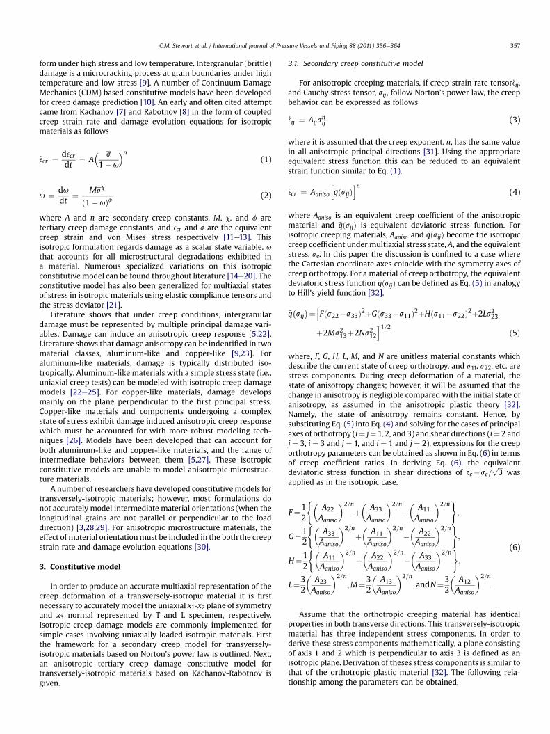
where Aaniso is an equivalent creep coefficient of the anisotropicmaterial and ~qðsijÞ is equivalent deviatoric stress function. Forisotropic creeping materials, Aaniso and ~qðsijÞ become the isotropiccreep coefficient under multiaxial stress state, A, and the equivalentstress, se. In this paper the discussion is confined to a case wherethe Cartesian coordinate axes coincide with the symmetry axes ofcreep orthotropy. For a material of creep orthotropy, the equivalentdeviatoric stress function ~qðsijÞ can be defined as Eq. (5) in analogyto Hill’s yield function [32].
~q�sij
�¼hFðs22�s33Þ2þGðs33�s11Þ2þHðs11�s22Þ2þ2Ls223
þ2Ms213þ2Ns212i1=2 ð5Þ
where, F, G, H, L, M, and N are unitless material constants whichdescribe the current state of creep orthotropy, and s11, s22, etc. arestress components. During creep deformation of a material, thestate of anisotropy changes; however, it will be assumed that thechange in anisotropy is negligible compared with the initial state ofanisotropy, as assumed in the anisotropic plastic theory [32].Namely, the state of anisotropy remains constant. Hence, bysubstituting Eq. (5) into Eq. (4) and solving for the cases of principalaxes of orthotropy (i¼ j¼ 1, 2, and 3) and shear directions (i¼ 2 andj ¼ 3, i ¼ 3 and j ¼ 1, and i ¼ 1 and j ¼ 2), expressions for the creeporthotropy parameters can be obtained as shown in Eq. (6) in termsof creep coefficient ratios. In deriving Eq. (6), the equivalentdeviatoric stress function in shear directions of se¼se=
ffiffiffi3
pwas
applied as in the isotropic case.
F¼12
(�A22
Aaniso
�2=n
þ�
A33
Aaniso
�2=n
��
A11
Aaniso
�2=n);
G¼12
(�A33
Aaniso
�2=n
þ�
A11
Aaniso
�2=n
��
A22
Aaniso
�2=n);
H¼12
(�A11
Aaniso
�2=nþ�
A22
Aaniso
�2=n��
A33
Aaniso
�2=n);
L¼32
�A23
Aaniso
�2=n
;M¼32
�A13
Aaniso
�2=n
;andN¼32
�A12
Aaniso
�2=n
:
(6)
Assume that the orthotropic creeping material has identicalproperties in both transverse directions. This transversely-isotropicmaterial has three independent stress components. In order toderive these stress components mathematically, a plane consistingof axis 1 and 2 which is perpendicular to axis 3 is defined as anisotropic plane. Derivation of theses stress components is similar tothat of the orthotropic plastic material [32]. The following rela-tionship among the parameters can be obtained,
C.M. Stewart et al. / International Journal of Pressure Vessels and Piping 88 (2011) 356e364358
G ¼ F; N ¼ Gþ 2H; andM ¼ L (7)
inserting these relationships into Eq. (6) gives the following
A11 ¼ A22; and A23 ¼ A13; and 2N ¼ 3�
A12
Aaniso
�2=n
¼ 4�
A22
Aaniso
�2=n
��
A33
Aaniso
�2=n
(8)
Since the creep orthotropy parameters were defined in terms ofthe ratios of the creep coefficients as shown in Eq. (6), it can beargued that the equivalent creep coefficient Aaniso be equal to A33 onthe longitudinal direction which is perpendicular to the 1e2 plane(i.e., transverse microstructure plane). Hence, the equivalentdeviatoric stress function for the transversely-isotropic creepingmaterial becomes as follows,
~q�sij
� ¼12ðs22 � s33Þ2þ
12ðs33 � s11Þ2þ
(�A22
A33
�2=n�12
)
�ðs11 � s22Þ2þ3�A13
A33
�2=ns223 þ 3
�A13
A33
�2=ns213
þ(4�A22
A33
�2=n�1
)s212
#1=2(9)
Consequently, for the transversely-isotropic material theequivalent deviatoric stress function can be determined if onlythree coefficients, A22 (transverse specimen), A33 (longitudinalspecimen) and A13 (45�-oriented specimen) are known. Then, creepbehavior of the transversely-isotropic material can be predicted asfollows
_ecr ¼ A33
h~q�sij
�in(10)
3.2. Tertiary creep damage constitutive model
The novel anisotropic tertiary creep damage model fortransversely-isotropic materials is based on the isotropicKachanov-Rabotnov creep damage constitutive model [7,8]. Theinfluence of the state of damage,u is accounted for via the effective(net) stress tensor, ~s. A number of formulations for the effectivestress have been proposed [9]. Murakami [25] and Murakami andOhno [33] proposed the symmetric effective (net) stress, ~s anddamage applied, U as
U ¼ ðI�uÞ�1;
~s ¼ 12ðsUþUsÞ; (11)
where s is the Cauchy stress tensor and U is damage applied.For anisotropic materials, the orientation of the material grain
structure relative to the general coordinates system can significantlyalter the damage developed. Thus to account for material orientationthe material damage constants need to be formulated into a tensorthat alters each tensorial term based on amaterial orientation vector,
Table 1Nominal chemical composition (wt.%) of DS GTD-111 superalloy [37].
n where the vector represents the direction of longitudinal grains.The rotated damage constant tensor, B is defined here as
B ¼hM2ðsHillÞc2
�I � nnT
�þM1ðsHillÞc1
�nnT
�i; (12)
where M1, M2, c1, c2 are damage constants and sHill is the Hillequivalent stress [32] from the Cauchy stress defined as
sHill ¼ffiffiffiffiffiffiffiffiffiffiffiffisTMs
p
s ¼ ½s11 s22 s33 s12 s23 s13 �T
M ¼
26666664
Gþ H �H �G 0 0 0�H F þ H �F 0 0 0�G �F F þ G 0 0 00 0 0 2N 0 00 0 0 0 2L 00 0 0 0 0 2M
37777775
(13)
where s is the vector form of the Cauchy stress tensor, s and M isthe Hill compliance tensor consisting of the F, G, H, L, M, and Nunitless material constants that can be obtained from creep tests[34]. The rotated damage constant tensor, F is defined as
FR ¼ f2
�I � nnT
�þ f1�nnT
��F ¼ ABS
�FR
�or Fij ¼ jFR
ijj(14)
where f1, and f2 are damage constants. The rotated damageconstant tensor, F is used as an elementwise exponent in latermathematics so it is necessary to ensure each element remainspositive. The ABS function is introduced which represents an ele-mentwise absolute value of the argument tensor. This is necessaryto prevent possible inversion in later analysis that would depend onthe selected plane of isotropy. The rotated damage constant tensorsallow the creep material properties to be directly related to theorientation of the material grain structure.
In the isotropic damage formulation Eq. (2), it is observed thatprevious scalar-valued damage is related by ð1� uÞ�f. An equiva-lent tensor form is produced by use of the elementwise Schur (orHadamard) power of the damage applied tensor, U and the rotateddamage constant tensor, F as follows
D ¼ UF��!
¼ U+ðFÞ
D ¼
2664UF1111 UF12
12 UF1313
UF2121 UF22
22 UF2323
UF3131 UF32
32 UF3333
3775
(15)
where the convenient tensor, D is later implemented in the damagerate tensor [35,36]. To account for both aluminum and copper-like,the damage control variable, g is introduced. This term is applied inthe first principal stress influence tensor as follows
X ¼ ½ð1� gÞIþ gðn1nT1Þ�
0:0 � g � 1:0(16)
where n1 represents the first principal stress direction vector.When g ¼ 0.0 isotropic damage is isotropically distributed whilewhen g ¼ 1.0 damage induced anisotropy is allowed to occur.
C.M. Stewart et al. / International Journal of Pressure Vessels and Piping 88 (2011) 356e364 359
To produce the damage rate tensor, _u, a multiplicative super-position of the rotated damage constant tensor, B and the conve-nient tensor, D which both account for material orientation isperformed. This is followed by a symmetric product with the firstprincipal stress influence tensor, X. The elementwise Schur (orHadamard) product is used
The B and D tensors are both rotations of the material orienta-tion [35,36]. As discussed earlier, undesirable terms develop intensor D. The Schur product with B eliminates them. The damagerate tensor is coupled with the anisotropic creep strain rate equa-tion defined as follows
Table 2Creep deformation and rupture data for DS GTD-111 [38].
Temperature (�C) Stress MPa Rupture Strain (%) Rupture Time
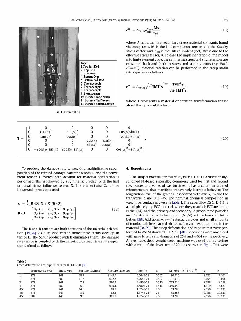
where Aaniso, naniso are secondary creep material constants foundvia creep tests, M is the Hill compliance tensor, s is the Cauchystress vector, and ~sHill is the Hill equivalent (net) stress due to theeffective stress tensor, ~s. To ease the implementation of the modelinto finite element code, the symmetric stress and strain tensors areconverted back and forth to stress and strain vectors (e.g. ~s%~s,ecr%ecr). Material rotation can be performed in the creep strainrate equation as follows
where T represents a material orientation transformation tensorabout the x1 axis of the form
4. Experiments
The subject material for this study is DS GTD-111, a directionally-solidified Ni-based superalloy commonly used for first and secondrow blades and vanes of gas turbines. It has a columnar-grainedmicrostructure that manifests transversely-isotropic behavior. Thelongitudinal axis of the grains is associated with axis x3, while thetransverse plane is x1ex2. The nominal chemical composition inweight percentage is given in Table 1. The superalloy DS GTD-111 isa dual phase geg0 FCCmaterial, where the gmatrix is FCC austeniticNickel (Ni), and the primary and secondary g0 precipitated particlesare L12 structured nickel-aluminde (Ni3Al) with a bimodal distri-bution [38]. Additionally, geg0 eutectic, carbides and small amountsof topological close-packed phases s, d, h and laves are found in thematerial [38,39]. The creep deformation and rupture test were per-formed to ASTM standard E-139-96 [40]. Specimens were machinedwith gage lengths and diameters of 25.4 and 4.064mm respectively.A lever-type, dead-weight creep machine was used during testingwith a ratio of the lever arm of 20:1 as shown in Fig. 1. Test were
L FEM ANIT FEM ANI45° FEM ANIL FEM ISOT FEM ISO45° FEM ISO
C.M. Stewart et al. / International Journal of Pressure Vessels and Piping 88 (2011) 356e364360
performed on longitudinal (L), transverse (T), and 45�-orientedspecimen. A list of the creep deformation and rupture tests withsecondary and tertiary creep damage constants is provided inTable 2. In all cases, the primary creep that arose was smallcompared to the final rupture strain and is neglected. The micro-structure of all the samples will be left for future work.
Time, t (hrs)
0 200 400 600 8000.0
0.1
Fig. 3. Damage evolution on the x3 normal of the isotropic and novel anisotropic creepdamage formulations under 289 MPa uniaxial load and 871 �C.
5. Results
Previous research using the isotropic Kachanov-Rabotnovconstitutive model has produced both secondary and tertiarycreep damage constants that can be used directly in the novelconstitutive model. The novel anisotropic tertiary creep damageconstitutive model requires material constants found throughuniaxial creep test in L, T, and 45�-orientations. This is due to theuse of Hill’s analogy as both a compliance tensor and equivalentstress in the creep strain rate Eq. (19). To determine the Hillconstants, the creep strain rate, Eq. (19), is taken with the damagerate, Eq. (17), disabled via M1 ¼ 0.0 and M2 ¼ 0.0. Various stresstransformations and material orientation transformations (aboutthe x1 normal) are performed. The Hill constants are found to bedependent on the uniaxial Norton-power law for L, T, and 45�-oriented specimen. Subsequently, the Hill constants can be referredback to the minimum strain rates found for L, T, and 45�-orientedspecimen. For this study, L, T, and 45�-oriented specimen creeptests were conducted at a temperature of 871 �C and 289 MPauniaxial load. The Hill constants for DS GTD-111 required by thenovel anisotropic creep damage formulation under these condi-tions are found in Table 3.
Verification of the secondary creep behavior can be achievedusing the creep strain rate, Eq. (19), with the damage rate, Eq. (17),disabled. In general, the secondary creep response of the material iscontrolled by the Aaniso, naniso and Hill constants F, G, H, L,M, and N.Disabling damage (M1 ¼ M2 ¼ 0.0) leads to the minimum creep
Fig. 2. Material orientation study of x3 normal minimum creep strain rate at 871 �C forvarious DS Ni-based materials.
strain rates found in Fig. 2. The observed curve follows the trendexpected of a Hill potential based model compared to other DS Ni-based superalloys [41e44]. The FEM prediction of minimum creepstrain rates pass through the known rates for L, T, and 45�-orientedspecimen at 289 MPa. The material behavior observed in the279 MPa experiment at a ¼ 0.0� is inconsistent with the studyresponse. Pre-existing flaws in the specimen account for theobserved high minimum creep strain rate.
Accurate estimates of damage evolution lead to high quality fitsof the creep deformation data. For these purposes, the damage rateEq. (17) is enabled. Simulations of L, T, and 45�-oriented specimensare executed and compared with those developed using theisotropic creep damage formulation. Fig. 3 shows that the novelanisotropic formulation produces similar damage evolution to theisotropic Kachanov-Rabotnov damage evolution for L and T-oriented specimen; however, the behavior of the 45�-orientedspecimen is not accurately modeled. This disconnect is expected.Not directly including the tertiary creep damage constants associ-ated with the 45�-oriented specimen will naturally lead to a lessthan ideal estimation of damage evolution when compared to the
Fig. 4. Creep deformation on the x3 normal of novel anisotropic and isotropic creepdamage formulations compared with creep test data for DS GTD-111 under 289 MPauniaxial load and 871 �C.
Fig. 5. Components of the creep deformation using the novel anisotropic creep damage formulation for (a) L, (b) T, and (c) 45�-oriented specimen under 289 MPa uniaxial load and871 �C (note: primary creep is neglected).
Fig. 6. Material orientation study (a) creep deformation and (b) damage evolution on the x3 axis (note: g ¼ 0.0).
C.M. Stewart et al. / International Journal of Pressure Vessels and Piping 88 (2011) 356e364 361
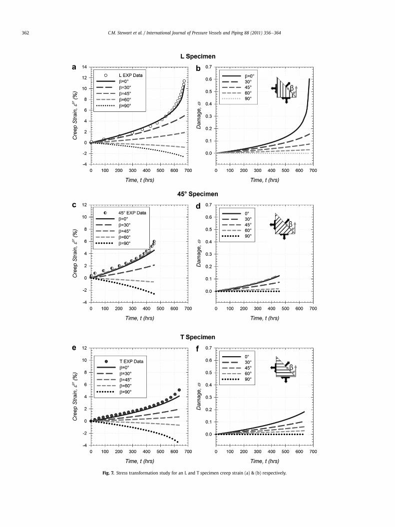
Fig. 7. Stress transformation study for an L and T specimen creep strain (a) & (b) respectively.
C.M. Stewart et al. / International Journal of Pressure Vessels and Piping 88 (2011) 356e364362
C.M. Stewart et al. / International Journal of Pressure Vessels and Piping 88 (2011) 356e364 363
isotropic creep damage model. The damage behavior embedded inthe novel anisotropic model considers a linear relationshipbetween the L and T-oriented specimen based on material orien-tation transformation; however, the behavior of DS GTD-111exhibits a maximized creep strain rate at an orientation between35� and 45�. While, the predicted damage evolution is not neces-sarily the same, it is found through examination of the availablecreep tests data that only slight tertiary creep behavior is found at45� allowing for a good prediction of the creep strain rate at thisorientation.
With the aid of available the creep test data, the creep strainversus time from experimental data is compared with bothisotropic and novel anisotropic creep damage formulations. Fig. 4shows the novel anisotropic formulation performs very well inmodeling the creep test experimental data. The accurate predictionof creep strain for a 45�-oriented specimen demonstrates thatdespite a damage evolution that diverges from the isotropic solu-tion, the novel anisotropic creep damage formulation can accu-rately predict the creep deformation that develops in transversely-isotropic materials under arbitrary material orientations. Thus therelationship between creep behavior, material orientation, andstate of stress are taken into account.
The tensor creep strain behavior of the novel anisotropic creepdamage model is of high importance. An accurate creep straintensor for the subject material proves considerably improvedestimations of creep deformation for directionally-solidifiedcomponents compared to the isotropic creep damage formulation.
Assuming g ¼ 0.0, the creep strain tensor response of L, T, and45�-oriented specimens are presented in Fig. 5. In the case of an Lspecimen (Fig. 5a), the creep strains found on the x1 and x2 normalsare equivalent. This is suitable as it shows that isotropy is found onthe x3 axis as expected of an L specimen. In the case of a T specimen(Fig. 5b), the creep strain on the x2 normal is higher than whatdevelops on the x3 normal. This is suitable because isotropicbehavior is now found on the x1-x3 plane. The L grains producea higher creep strain rate thus the x2 normal is higher than the x3normal. In the case of a 45�-oriented specimen (Fig. 5c), the creepbehavior on the x2 normal and x3 normal is the same, however; dueto uniaxial loading the creep strain that develops in the x2 normal iscompressive due to the deviatoric response.
In the case of the isotropic creep damage formulation, most FEMcodes generalize a full strain tensor via isotropic material proper-ties [45]. In the case of a transversely-isotropic material this wouldnot produce an accurate result. Thus, the novel anisotropic model isfound to produce a more accurate strain tensor.
6. Parametric study
A parametric study of the damage and creep strain that developson the x3 normal under different material orientations about the x1axis was conducted. Under 289 MPa tensile loading and 871 �C, thedamage evolution and creep deformation is shown in Fig. 6. In caseof creep deformation that difference in creep strain rates betweenthe various orientations follows thematerial behavior fairly well. Inthe case of damage evolution, some shortcomings are noticed.Particularly that the trajectory of damage evolution of intermediateorientations does not change much compared to the L and T-oriented specimen. This would produce rupture predictions that donot follow experimental trends. When damage evolution is maxi-mized, the creep deformation is minimal.
A parametric study of the damage and creep strain that developson the x3 normal under different stress transformations on L, 45�,and T-oriented specimenwas performed. The stress transformationtakes the following form
s0 ¼ QsQ T ¼240 0 00 0 00 0 s0
35
Q ¼241 0 00 cosðbÞ sinðbÞ0 �sinðbÞ cosðbÞ
35 (21)
where rotation occurs about the x1 axis and s0 equals 289 MPa. Itshould be noted that g¼ 1.0, thus thematerial is assumed to behavelike a fully anisotropic damaging material where damage coincideswith the first principal stress direction. In all three specimen, thedamage reduces to zero as stress transformed from fully on the x3normal to the x2 normal. In the case of creep strain, all threespecimens at b ¼ 0.0 begin at earlier predicted creep strain rates(Fig. 7); however, due to TMTTs found in the creep strain rate Eq.(19), at a certain angle between 45� and 60�, tensile creep defor-mation changes to a compressive deformation due to the deviatoricresponse. Further examination of shear creep terms finds that thenovel anisotropic model is able to account for elongation andangular distortions.
7. Conclusions
It was observed that the aforementioned constitutive modelperforms well at predicting the creep deformation behavior ofa directionally-solidified Ni-based superalloy. The constitutivemodel was found to accurately, predict the creep deformation of L,45�, and T-oriented uniaxial specimen of DS GTD-111. Additionally,parametric material orientation and stress rotation simulationsinform that the creep strain model can account for multiaxial statesof stress and intermediate orientations. In terms of modelingdamage, damage evolution at intermediate orientation was foundto not correspond well with experimental trends. A better damageevolution model would be necessary to produce accurate rupturetime predictions and damage contour plots. Future work will focuson normalization of the damage criterion in all orientations to unityand developing an improved damage evolution model.
Acknowledgments
Calvin Stewart is thankful for the support of a Mcknight DoctoralFellowship through the Florida Education Fund. Ali P. Gordonrecognizes the support of the Florida Center for Advanced Aero-Propulsion (FCAAP).
References
[1] National Research Council (U.S.). Committee on materials for large land-basedgas turbines. Materials for large land-based gas turbines. US: NationalAcademy Press; 1986.
[2] Pridemore WD. Stress-rupture characterization in nickel-based superalloy gasturbine engine components. Journal of Failure Analysis and Prevention 2008;8(3):281e8.
[3] Naumenko K, Altenbach H. A phenomenological model for anisotropic creepin a multipass weld metal. Archive of Applied Mechanics 2005;74(11e12):808e19.
[4] Ohno N, Mizuno T, Kawaji H, Okada I. Multiaxial creep of a nickel-basedirectionally solidified alloy: anisotropy and simulation. Acta Metallurgica etMaterialia 1992;40(3):559e67.
[5] Altenbach H, Huang C, Naumenko K. Creep damage predictions in thin-walledstructures by use of isotropic and anisotropic damage models. Journal ofStrain Analysis for Engineering Design 2002;37(3):265e75.
[6] Shesterikov SA, Lokochtchenko AM, Mjakotin EA. Creep rupture of anisotropicpipes. Journal of Pressure Vessel Technology 1998;120(3):223e5.
[7] Kachanov LM. Time to rupture process under creep conditions. Izv Akad Nank1958;8:26e31.
[8] Rabotnov YN. Creep problems in structural members. North Holland: North-Holland Publ. Co; 1969.
C.M. Stewart et al. / International Journal of Pressure Vessels and Piping 88 (2011) 356e364364
[9] Skrzypek J, Ganczarski A. Modeling of material damage and failure of struc-tures. New York: Springer; 1999.
[10] Betten J. Creep mechanics. New York: Springer; 2002.[11] Altenbach J, Altenbach H, Naumenko K. Edge effects in moderately think
plates under creep damage conditions. Technische Mechanik 2004;24(3e4):254e63.
[12] Hyde TH, Becker AA, Sun W. Creep damage analysis of short cracks usingnarrow notch specimen made from a Ni-base superalloy at 700�C. 10thInternational Conference on Fracture. Honolulu, Oahu, HI. Oxford, UL: ElsevierScience; 2001 Dec 2e6 [International Congress on Fracture].
[13] Stewart CM, Gordon AP. Modeling the temperature-dependence of tertiarycreep damage of a Ni-base alloy. ASME Early Career Technical Journal 2008;7(1):1e8.
[14] Stewart CM, Gordon AP. Modeling the temperature dependence of tertiarycreep damage of a Ni-base alloy. Journal of Pressure Vessel Technology 2009;131(5):1e11.
[15] Leckie FA, Hayhurst DR. Constitutive equations for creep rupture. Acta Met-allurgica 1977;25:1059e70.
[16] Leckie FA, Ponter A. On the state variable description of creeping materials.Ingenieur Archiv 1974;43:158e67.
[18] Hyde TD, Sun W, Williams JA. Creep behaviour of parent, weld and HAZmaterials of new, service-aged and repaired 1/2Cr1/2Mo1/4V: 2 1/4Cr1Mopipe welds at 640�C. Material at High Temperatures 1999;16(3):117e29.
[19] Maclachlan DW, Knowles DM. Creep-behavior modeling of the single-crystalsuperalloy CMSX-4. Metallurgical and Materials Transactions A 2000;31(5):1401e11.
[20] Batsoulas ND. Creep damage assessment and lifetime predictions for metallicmaterials under variable loading conditions in elevated temperature appli-cations. Steel Research International 2009;80(2):152e9.
[22] Murakami S, Sanomura Y. Creep and creep damage of copper under multiaxialstates of stress. In: Sawczuk A, Bianci G, editors. Plasticity today. New York:Elsevier Applied Science Publishers; 1985. p. 535e51.
[23] Trampczynski WA, Hayhurst DR, Leckie FA. Creep rupture of copper andaluminum under non-proportional loading. Journal of the Mechanics andPhysics of Solids 1981;29(5e6):353e74.
[24] Betten J, El-Magd E, Meydanli S, Palmen P. Bestimmung der Materi-alkennwerte einer dreidimensionalen Theorie zur Beschreibung des tertia€renKriechverhaltens austenitischer Sta€hle auf der Basis der Experimente. Archiveof Applied Mechanics 1995;65(2):110e20.
[25] Murakami S. A continuum mechanics theory of anisotropic damage. In:Boehler JP, editor. Yielding, damage and failure of anisotropic solids. London:Mechanical Engineering Publications; 1990. p. 465e82.
[26] Hayhurst DR. Creep rupture under multi-axial states of stress. Journal of theMechanics and Physics of Solids 1972;20(6):381e2.
[27] Stewart CM, Gordon AP. Numerical simulation of temperature-dependent,anisotropic tertiary creep damage. 47th AIAA aerospace sciences meeting
including the new horizons forum and aerospace exposition. Orlando, Fl; Jan5e8 2009.
[28] Hyde TH, Sun W. Creep failure behavior of a circumferential P91 pipe weld-ment with an anisotropic weld metal subjected to internal pressure and endload. Proceedings of the Institution of Mechanical Engineers, Part L: Journal ofMaterials Design and Applications 2006;220(3):147e62.
[29] Peravali S, Hyde TH, Cliffe KA, Leen SB. Development and use of an anisotropicdamage model for the high-temperature life assessment of a P91 weldment.Journal of Strain Analysis for Engineering Design 2008;43(5):361e82.
[30] Peravali S, Hyde TH, Cliffe KA, Leen SB. An anisotropic creep damage model foranisotropicweldmetal. Journalof PressureVessel Technology2009;131(2):1e8.
[31] Bhatnagar NS, Gupta RP. On the constitutive equations of the orthotropictheory of creep. Wood Science and Technology 1967;1:142e8.
[32] Hill R. The mathematical theory of plasticity. Oxford: Clarendon Press, OxfordEngineering Science Series.
[33] Murakami S, Ohno N. A continuum theory of creep and creep damage. In:Ponter ARS, Hayhurst DR, editors. Creep in structures; 1981. p. 422e43.
[34] Hyde TH, Jones IA, Peravali S, Sun W, Wang JG, Leen SB. Anisotropic creepbehavior of Bridgman Notch specimens. Proceedings of the Institution ofMechanical Engineers, Part L Journal of Materials: Design and Applications2005;219(3):163e75.
[35] Schur I, Joseph A, Melnikov A, Rentschler R. Studies in memory of Issai Schur.New York: Springer; 2003.
[36] Bernstein DS. Matrix mathematics. Princeton, New Jersey: Princeton Univer-sity Press; 2005. pp. 252e253.
[37] Schilke PW, Foster AD, Pepe JJ, Beltran AM. Advanced materials propelprogress in land-based gas turbines. Advanced Materials and Processes 1992;141(4):22e30.
[38] Ibanez AR, Srinivasan VS, Saxena A. Creep deformation and rupture behaviourof directionally-solidified GTD 111 superalloy. Fatigue & Fracture of Engi-neering Materials & Structures 2006;29(12):1010e20.
[39] Sajjadi SA, Nategh S. A high temperature deformation mechanism map for thehigh performance Ni-base superalloy GTD-111. Materials Science and Engi-neering A 2001;307(1e2):158e64.
[40] ASTM E-139. Standard test methods for conducting creep, creep-rupture, andstress-rupture tests of metallic materials. No. 03.01. West Conshohocken, PA.
[41] Gordon AP, Shenoy MM, McDowell DL. Simulation of creep crack growth ofa directionally-Solidified Ni-base superalloy. In: proceedings of the 11thinternational conference on fracture. Turlin, Italy; 2005 March 20e25.
[42] Peterson LG, Hrencecin D, Ritter A, Lewis N. Hip diffusion bonding of P/Malloys for composite land-based gas turbine buckets. Progress in PowderMetallurgy 1986;41:561e78.
[43] Woodford DA, Frawley JJ. Effect of grain boundary orientation on creep andrupture of In-738 and nichrome. Metallurgical Transactions 1974;5(9):2005e13.
[44] Sessions ML, McMahon CJ. Influence of stress components on intergranularoxidation and cracking in a nickel-base superalloy. Nuclear Technology;1975:477e89.
[45] ANSYS Inc. Theory reference for ANSYS and ANSYS workbench. Canonsburg,PA: ANSYS Inc.; 2007. pp. 103e105.