Performance Analysis of 33/11kv Substation and its Feeders
Mohmmedfuzail bilagi, Dr. S G Ankaliki, SDM of Engg and Tech Dharwad
Abstract —Electrical power system provide a vital service to the society. For healthy operation of electrical power generation, transmission and distribution, it is important that system should be balanced. Load flow is basic requirement to conduct power system analysis of any system. The load flow gives us information about voltages, real and reactive power generated and absorbed and line losses across the entire system. Short Circuit Analysis provides the information required to determine whether the interrupting capacities of the power system components are adequate enough to protect your power system. Also this data is used to evaluate the proper sizing of protective relays and sensing equipment. All the data used for analysis is real time and collected from 33/11kV substation.This paper deals with the simulation of 33/11kV substation. The analysis is done by using advance software Electrical Transient Analyser Program (ETAP) and MI POWER with detailed load flow analysis.Also, carried out the short circuit study of 33/11 kV substation system using ETAP software. From the ETAP and MI POWER generated load flow details and the short circuit details are studied.
Index term— ETAP, MI POWER, load flow, short circuit, 33/11kv substation, comparision, reactive compensation, Newton raphson method
—————————— ——————————
1 INTRODUCTION
Electrical power system is back bone of the development of a nation. There is big issue of power quality for developed na-tions but the developing countries like India the load is in-creasing rapidly but generation is not up to the level of de-mand [1]. Hence there is need of load flow management. Load flow analysis using software is accurate and gives highly reli-able results. This research makes effective use of Electrical Transient Analyzer Program (ETAP) to carry out load flow analysis of 33kV substation. The actual ratings of Power Transformers, Circuit Breakers, Current Transformers, Poten-tial Transformers and Isolating switches are taken and mod-elled accordingly in ETAP.[2] This 33kV substation is located in Bagalkot district jamkahndi taluk Hirepadsalgi owned by Karnataka HESCOM.
The major cause of almost all power system disturbances is under voltage, voltage drops and power factor. In order to identify and pinpoint these disturbances, load flow studies are conducted. The result of these studies help to address the sys-tem disturbances with the help of additional devices (capaci-tors..etc). [3][4]
Short circuits can occur anywhere in the system. In order to protect the system against short circuits, it is necessary to in-stall circuit breakers which can safely isolate the circuit in fault conditions. The results of these studies help in proper selec-tion & settings of protective device such as fuses, circuit breakers, and relays used in the protection scheme. Thus help-ing utilities maintain a safe, reliable and efficient electrical distribution system [5].
The single line diagram of the substation is simulated in ETAP based upon actual data, and it is seen that at the 11kV feeder buses. To overcome the under voltage at the 11kV feeder bus-es buses capacitor bank of suitable ratings are added. [6]
Section 1 is introduction of ETAP software. Section 2 is the
details of the components. Section 3 is the simulation of single line diagram of 33 kV substation in ETAP based upon practical data. Section 4 is the Load Flow Analysis of the substation. Three conditions have been simulated in order to analyse the behaviour of the power system in these situations. Section 5 contains the observations on the load flow analysis. Section 6 is the recommendation to correct the problems encoun-tered.[10]
2 METHEDOLOGY 2.1 The step by step methods involves the analysis are: 1. Data collection from the Herepadsalgi 33kv Substation2. Simulation of the Herepadsalgi Substation using ETAP3. Calculation of Fault Current and Line Impedance using
symmetrical method for fault analysis4. Validation of Fault current using ETAP
5. Determination of the bus voltage, Real and reactive pow-er from the load flow analysis using MI POWER
2.2 Data Collected for 33KV Current Transformer Product of C. T=ABB C.T Ratio=300:1RHSV 36KV, 800AType =outdoorFrequency =50 HzBurden =15VA coreC.T Ratio=300:5[7]
2..3 CALCULATIONThe 10 MVA transformer is connected in Delta/Star
Base current = 1000(MVA)b/√3 (KV)b Base impedence = (KV)b^2/(MVA)b Reactive Power=VrmsIrms = Irms^2X Active Power=√3 VI COS ø
International Journal of Scientific & Engineering Research Volume 10, Issue 5, May-2019 ISSN 2229-5518
2.4 Sequence impedance Z0=(Zs+2Zm) Z1=Z2=(Zs-Zm) z = √R2 + (ѡL)^2(11)
2.5 Single line to groun
Ia1=Ia2=Ia0=[Vf/(Z1+Z2+Z0+3*Zf)] Where Ib=Ic=0; Symmetrical components of voltage from terminals ‘a’ to ground Va1=Va2=Vf-Ia1*Z1 Va0=-Ia0*Z0 Line to ground voltage Va=Va1+Va2+Va0 Vb=a^2*Va1+a*Va2+Va0 Where a =0.5+j0.86660 Vc=a*Va1+a^2*Va2+Va0 Line to line voltage fault Vab=Va-Vb Vbc=Vb-Vc Vca=Vc-Va 2.6 line to line Fault occurred between b and c Vb-Vc=Ib*Zf; Ia=-Ic Ia1=[Vf/(Z1+Z2+Zf)]=-Ia1 Ia0=0 Ia=Ia1+Ia2+Ia0 Ib=a^2*Ia1+a*Ia2+Ia0 Ic=a*Ia1+a^2*Ia2+Ia0 Symmetrical components of voltage from terminal a to ground Va1=Vf-Ia1*Z1 Va2=-Ia2*Z2 Va0=0 Line to ground voltage Va=Va1+Va2+Va0 Vb=a^2*Va1+a*Va2+Va0 Where a =0.5+j0.86660 Vc=a*Va1+a^2*Va2+Va0[8][9]
2.6 line to line ground
Fault occurred between b, c and ground with Zf=0 Ia1=[Vf/{Z1+(Z2*Z0/Z2+Z0)}] Ia2=-Va2/Z2 Ia0=Va0/Z0 If=Ib+Ic Vb=Vc=0 Va=Va0+Va1+Va2
2.7 3 phase fault Ia1=Vf/Z1 If=4*base current
TABLE 2 SHOWS THE IMPEDENCE OF VARIOUS NODE OF SUBSTATION
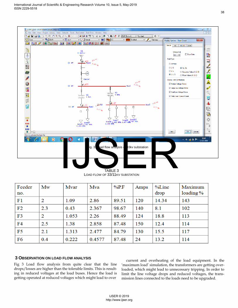
3 OBSERVATION ON LOAD FLOW ANALYSISFig 3 Load flow analysis from quite clear that the line drops/losses are higher than the tolerable limits. This is result-ing in reduced voltages at the load buses. Hence the load is getting operated at reduced voltages which might lead to over
current and overheating of the load equipment. In the ‘maximum load’ simulation, the transformers are getting over-loaded, which might lead to unnecessary tripping. In order to limit the line voltage drops and reduced voltages, the trans-mission lines connected to the loads need to be upgraded.
TABLE 3 LOAD FLOW OF 33/11KV SUBSTATION
Fig. 3. Load flow analysis of 33kv substation
International Journal of Scientific & Engineering Research Volume 10, Issue 5, May-2019 ISSN 2229-5518
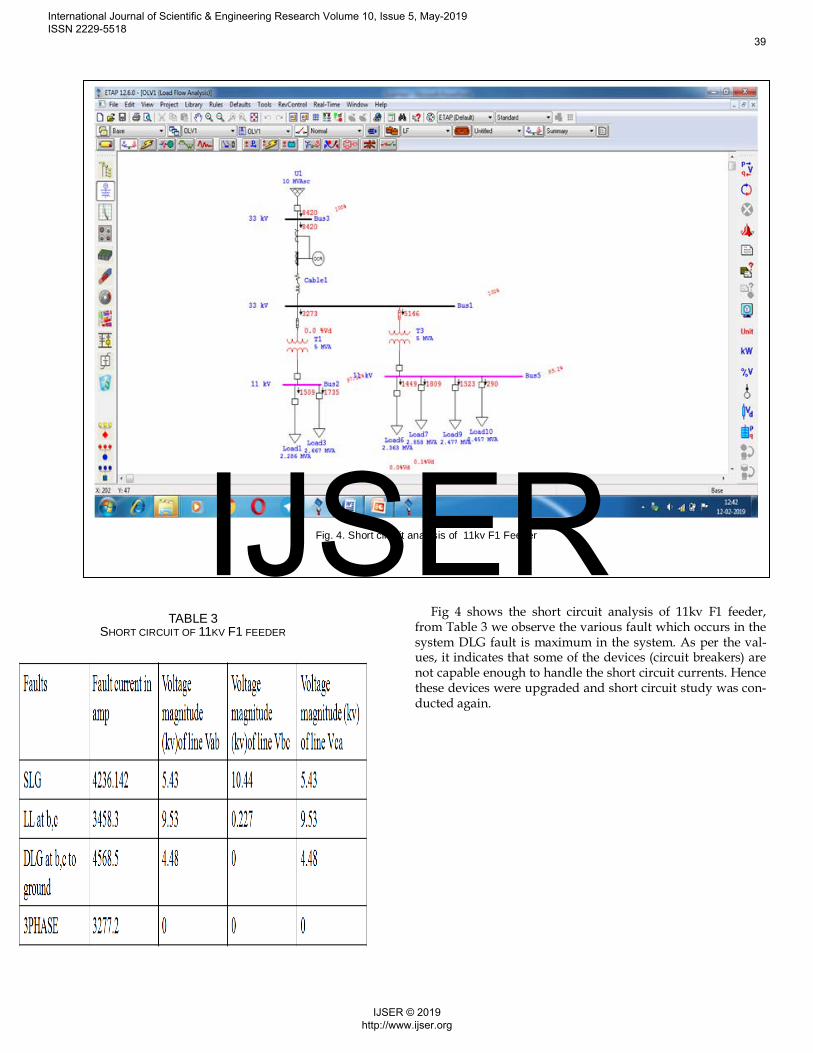
Fig 4 shows the short circuit analysis of 11kv F1 feeder, from Table 3 we observe the various fault which occurs in the system DLG fault is maximum in the system. As per the val-ues, it indicates that some of the devices (circuit breakers) are not capable enough to handle the short circuit currents. Hence these devices were upgraded and short circuit study was con-ducted again.
TABLE 3 SHORT CIRCUIT OF 11KV F1 FEEDER
Fig. 4. Short circuit analysis of 11kv F1 Feeder
International Journal of Scientific & Engineering Research Volume 10, Issue 5, May-2019 ISSN 2229-5518
In this paper, fault analysis was carried out for 33/11kv Substation. The analysis was carried manually using symmetrical components method. The results were compared with software solutions obtained from ’ETAP and MI POWER ’ to validate the hand calculations’ accuracy. The error was between the acceptable limit of 3.2% for all type of fault. Load-flow studies are important for planning future expansion of power systems as well as in determining the best operation of existing systems. In this paper analysis of 33/11 kV substation using ETAP and MI POWER software is carried out with an approach to overcome the problem of an under voltage, line losses and voltage drops. Load Flow Studies using ETAP software is an excellent tool for system planning. A number of operating procedures can be analysed such as the loss a Distribution line, a transformer or a load. This can be used to determine the optimum size and location of capacitors to surmount the problem of an under voltage. Also, they are useful in determining the system voltages under conditions of suddenly applied or disconnected loads. Load flow studies determine if system voltages remain within specified limits under various contingency conditions, and whether equipment such as transformers and conductors are overloaded. It was often used to identify the need for additionalgeneration, capacitive, or inductive VAR support, or the placement of capacitors and/or reactors to maintain system voltages within specified limits. Short circuits studies are the most required in a power system in order to adequately size the
devices, so that they are capable to handle the short circuit currents. Also these studies provide information regarding the intensity and the probable damage which can be caused in the event of the short circuit. These studies also help to adequately design the protection system. And, equally important, short circuit study is the prerequisite for Relay Co-ordination and Arc Flash Studies.
REFERENCES [1] Rohit Kapahi, “Load Flow Analysis of 132 kV substation using ETAP Soft-
ware” International Journal of Scientific Engineering Research, vol. 4, issue 2, Feb 2013, pp. 1-5.
[2] HESCOM real time data[3] P. M. Anderson and A. A. Fouad, “Power System Control and Stabil-
ity”. New York: IEEE Press,1994. [4] Push Raj (2013), Load Flow and Short Circuit Analysis of 400/220kv
Substation, International Journal of Creative Research Thoughts, Vo-lume1, Issue.4.
[5] Zhang, L.D., Bollen, M.H.J. (1998) A method for characterizing unba-lanced voltage dips (sags) with symmetrical components. IEEEPower Eng.
[6] Asaduzzaman Nur, M. H. S., Muhit, M. S., and Md Khaled Hossain,M. D. (2014). Fault AnalysisElectrical Protection of DistributionTransformers. Global Journal of Research In Engineering, 14(3).
[7] Mageshvaran, R., Raglend, I.J., Yuvaraj, V., Rizwan khan, P.G., Vi-jayakumar, T. and Sudheera, “Implementation of Non-Traditional Optimization Techniques (PSO, CPSO, HDE) for the Optimal Load Flow Solution,” TENCON2008- 2008 IEEE Region 10 Conference, 19-21 November 2008.
[8] P. Kundur, 1. Paserba, V. Ajjarapu, G. Andersson, A. Bose, C. Cani-zares, et aI., "Definition and classification of power system stability", JEEE Trans. Power Syst., vol. 19, no. 3, pp. 1387-1401, Aug. 2004.
[9] J. H. Teng, "Unsymmetrical Short-Circuit Fault Analysis for WeaklyMeshed Distribution Systems," in IEEE Transactions on Power Sys-tems, vol. 25, no. 1, pp. 96-105, Feb. 2010. doi:10.1109/TPWRS.2009.2036485.
[10] A. Sinha, S. Pandey, A. Singhal, A. Sanyal and A. Schmaltz, "DFM-aware fault model and ATPG for intra-cell and inter-cell defects,"2017 IEEE International Test Conference (ITC), Fort Worth, TX, USA,2017, pp. 1-10.
TABLE 6
COMPARING THE CALCULATED AND SIMULATED RE-SULTS
International Journal of Scientific & Engineering Research Volume 10, Issue 5, May-2019 ISSN 2229-5518