Material-stiffening suppresses elastic fingering and fringe instabilities
Shaoting Lin
a , Yunwei Mao
a , Hyunwoo Yuk
a , Xuanhe Zhao
a , b , ∗
a Department of Mechanical Engineering, Massachusetts Institute of Technology, Cambridge, MA 02139, USA b Department of Civil and Environmental Engineering, Massachusetts Institute of Technology, Cambridge, MA 02139, USA
a r t i c l e i n f o
Article history:
Received 20 October 2017
Revised 16 January 2018
Available online xxx
Keywords:
Fingering instability
Fringe instability
Confined layers
Strain stiffening
Adhesives
a b s t r a c t
When a confined elastic layer is under tension, undulations can occur at its exposed surfaces, giving the
fingering or fringe instability. These instabilities are of great concern in the design of robust adhesives,
since they not only initiate severe local deformations in adhesive layers but also cause non-monotonic
overall stress vs. stretch relations of the layers. Here, we show that the strain stiffening of soft elastic
materials can significantly delay and even suppress the fringe and fingering instabilities, and give mono-
tonic stress vs. stretch relations. Instability development requires local large deformation, which can be
inhibited by material-stiffening. We provide a quantitative phase diagram to summarize the stiffening’s
effects on the instabilities and stress vs. stretch relations in confined elastic layers. We further use nu-
merical simulations and experiments to validate our findings.
2 S. Lin et al. / International Journal of Solids and Structures 0 0 0 (2018) 1–9
ARTICLE IN PRESS
JID: SAS [m5G; February 8, 2018;18:22 ]
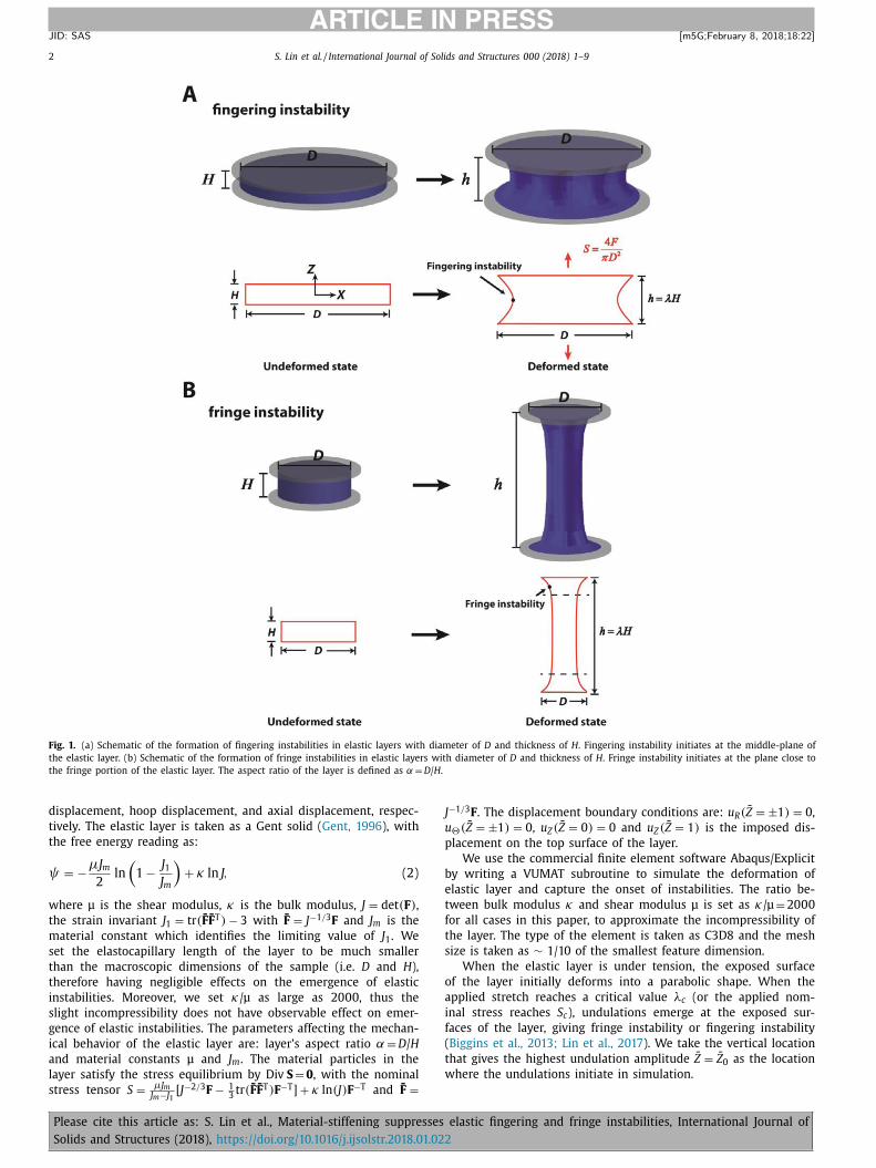
Fig. 1. (a) Schematic of the formation of fingering instabilities in elastic layers with diameter of D and thickness of H . Fingering instability initiates at the middle-plane of
the elastic layer. (b) Schematic of the formation of fringe instabilities in elastic layers with diameter of D and thickness of H . Fringe instability initiates at the plane close to
the fringe portion of the elastic layer. The aspect ratio of the layer is defined as α = D / H .
J
u
p
b
e
t
f
t
s
o
a
i
f
(
t
w
displacement, hoop displacement, and axial displacement, respec-
tively. The elastic layer is taken as a Gent solid ( Gent, 1996 ), with
the free energy reading as:
ψ = −μJ m
2
ln
(1 − J 1
J m
)+ κ ln J, (2)
where μ is the shear modulus, κ is the bulk modulus, J = det (F ) ,
the strain invariant J 1 = tr ( ̄F ̄F T ) − 3 with F̄ = J −1 / 3 F and J m
is the
material constant which identifies the limiting value of J 1 . We
set the elastocapillary length of the layer to be much smaller
than the macroscopic dimensions of the sample (i.e. D and H ),
therefore having negligible effects on the emergence of elastic
instabilities. Moreover, we set κ/μ as large as 20 0 0, thus the
slight incompressibility does not have observable effect on emer-
gence of elastic instabilities. The parameters affecting the mechan-
ical behavior of the elastic layer are: layer’s aspect ratio α = D / H
and material constants μ and J m
. The material particles in the
layer satisfy the stress equilibrium by Div S = 0 , with the nominal
stress tensor S =
μJ m J m −J [ J −2 / 3 F − 1
3 tr ( ̄F ̄F T ) F −T ] + κ ln (J) F −T and F̄ =
1
Please cite this article as: S. Lin et al., Material-stiffening suppresses
Solids and Structures (2018), https://doi.org/10.1016/j.ijsolstr.2018.01.022
−1 / 3 F . The displacement boundary conditions are: u R ( ̄Z = ±1 ) = 0 ,
�( ̄Z = ±1 ) = 0 , u Z ( ̄Z = 0 ) = 0 and u Z ( ̄Z = 1 ) is the imposed dis-
lacement on the top surface of the layer.
We use the commercial finite element software Abaqus/Explicit
y writing a VUMAT subroutine to simulate the deformation of
lastic layer and capture the onset of instabilities. The ratio be-
ween bulk modulus κ and shear modulus μ is set as κ/μ = 20 0 0
or all cases in this paper, to approximate the incompressibility of
he layer. The type of the element is taken as C3D8 and the mesh
ize is taken as ∼ 1/10 of the smallest feature dimension.
When the elastic layer is under tension, the exposed surface
f the layer initially deforms into a parabolic shape. When the
pplied stretch reaches a critical value λc (or the applied nom-
nal stress reaches S c ), undulations emerge at the exposed sur-
aces of the layer, giving fringe instability or fingering instability
Biggins et al., 2013; Lin et al., 2017 ). We take the vertical location
hat gives the highest undulation amplitude Z̄ = Z̄ 0 as the location
here the undulations initiate in simulation.
elastic fingering and fringe instabilities, International Journal of
S. Lin et al. / International Journal of Solids and Structures 0 0 0 (2018) 1–9 3
ARTICLE IN PRESS
JID: SAS [m5G; February 8, 2018;18:22 ]
Fig. 2. (a) Illustration of the amplitude of undulations at various vertical locations. (b) The normalized amplitude A m / D versus vertical location Z̄ at the onset of fingering
instability in the layers with large aspect ratio (i.e. α = 14) for both non-stiffening layers (i.e. J m → ∞ ) and stiffening layers with various limits of strain invariant J m . The
vertical location with maximum amplitude identifies the vertical plane where undulations initiate (i.e. Z̄ 0 = 0 ), at middle-plane of the layer. (c) The normalized amplitude
A m / D versus vertical location Z̄ at the onset of fringe instability in the layers with small aspect ratio (i.e. α = 2) for both non-stiffening layers (i.e. J m → ∞ ) and stiffening
layers with various limits of strain invariant J m . The vertical location with maximum amplitude identifies the vertical plane where undulations initiate (i.e. Z̄ 0 = 0 . 8 ), close
to fringe portion. (d) The vertical plane where undulations initiate for the layers with various aspect ratios and various limits of strain invariant. For the samples with large
aspect ratio α in which fingering instability sets in, the instability initiates at the middle section of the exposed meniscus (i.e. Z̄ 0 = 0 ); while for the samples with small
aspect ratio α, the instability initiates at the fringe portion of the exposed meniscus (i.e. Z̄ 0 = 0 ), giving fringe instability.
Fig. 3. Theoretical and simulation results on the critical points of fingering instability and fringe instability. (a) Comparison of the critical stretch λc for the onset of
instabilities between theory and simulation. (b) Comparison of the critical mode number ω c between theory and simulation. Solid line denotes the theoretical results for
non-stiffening layers (i.e. J m → ∞ ). Solid circular dots denote simulations results for non-stiffening layers (i.e. J m → ∞ ). Hollow square dots, circular dots and triangular dots
denote simulation results for stiffening layers with J m = 24, J m = 45 and J m = 72.
Please cite this article as: S. Lin et al., Material-stiffening suppresses elastic fingering and fringe instabilities, International Journal of
Solids and Structures (2018), https://doi.org/10.1016/j.ijsolstr.2018.01.022
4 S. Lin et al. / International Journal of Solids and Structures 0 0 0 (2018) 1–9
ARTICLE IN PRESS
JID: SAS [m5G; February 8, 2018;18:22 ]
Fig. 4. Suppression of fingering instability in the sample with aspect ratio of α = 6. (a) Fingering instability emerges in a neo-Hookean layer. (b) Fingering instability sup-
pressed in a Gent solid with the limit of the strain invariant J m = 1.3. (c) The radius of the outer surface at the middle plane of the layer where undulations initiate and (d)
the maximum strain invariant ( J 1 ) max at the plane where instability initiates. Dots represent the onset of fingering instabilities.
F
m
f
t
a
v
d
a
F
f
i
n
J
m
e
s
f
s
3. Effects of material stiffening on fingering and fringe
instabilities
In previous study on non-stiffening materials (i.e. J m
→ ∞ ), we
find the aspect ratio α = D / H determines the selection of the mode
of instability ( Lin et al., 2017 ). As shown in Fig. 1 , for the sam-
ples with large aspect ratio α in which fingering instability sets in,
the instability initiates at the middle section of the exposed menis-
cus (i.e. Z̄ 0 = 0 ); while for the samples with small aspect ratio α,
the instability initiates at the fringe portion of the exposed menis-
cus (i.e. Z̄ 0 = 0 ), giving fringe instability. The critical aspect ratio
between fringe instability and fingering instability has been iden-
tified as αfringe − fingering = 5 for non-stiffening materials ( Lin et al.,
2017 ). Here, we further investigate the effect of material-stiffening
on αfringe − fingering by performing a set of numerical simulations for
the samples with various aspect ratios α ranging from 1 to 10
and various limits of the strain invariant (i.e. J m
= 24, J m
= 45 and
J m
= 72). We extract the contour of exposed surface at each verti-
cal location of the layer at the onset of instabilities as shown in
Please cite this article as: S. Lin et al., Material-stiffening suppresses
Solids and Structures (2018), https://doi.org/10.1016/j.ijsolstr.2018.01.022
ig. 2 a. The difference between the maximum radius r max and the
inimum radius r min defines the amplitude of the contour A m
. We
urther plot the normalized amplitude A m
/ D versus vertical loca-
ion Z̄ in the layer. As shown in Fig. 2 b, for the layers with large
spect ratio (i.e. α = 14) in which fingering instability sets in, the
ertical location that gives the maximum amplitude is at the mid-
le plane (i.e. Z̄ 0 = 0 ) for the layers in both non-stiffening layers
nd stiffening layers with J m
= 24, J m
= 45 and J m
= 72. As shown in
ig. 2 c, for the layers with small aspect ratio (i.e. α = 2) in which
ringe instability sets in, the vertical location that gives the max-
mum amplitude is at the plane Z̄ 0 = 0 . 8 for the layers in both
on-stiffening layers and stiffening layers with J m
= 24, J m
= 45 and
m
= 72. We summarize the vertical location that gives the maxi-
um amplitude at the onset of instabilities in both stiffening lay-
rs and non-stiffening layers. As shown in Fig. 2 d, the limit of the
train invariant J m
does not affect the critical aspect ratio between
ringe instability and fingering instability significantly, which is the
ame as that in a non-stiffening layer (i.e. αfringe − fingering = 5).
elastic fingering and fringe instabilities, International Journal of
S. Lin et al. / International Journal of Solids and Structures 0 0 0 (2018) 1–9 5
ARTICLE IN PRESS
JID: SAS [m5G; February 8, 2018;18:22 ]
Fig. 5. Suppression of fringe instability in the sample with aspect ratio of α = 1. (a) Fringe instability emerges in a neo-Hookean layer. (b) Fringe instability suppressed in a
Gent solid with the limit of the strain invariant J m = 9. (c) The radius of the outer surface at the plane Z̄ 0 = 0 . 9 where undulations initiate and (d) the maximum first strain
invariant ( J 1 ) max . Dots represent the onset of fringe instabilities.
o
m
f
n
t
i
c
w
p
J
h
t
p
fi
i
a
λ
w
g
m
i
fi
(
(
p
p
s
o
We further explore the effect of material-stiffening on the onset
f instabilities in elastic layers. In previous study on non-stiffening
aterials (i.e. J m
→ ∞ ), we derive the analytical solution of the de-
ormation field and predict the critical stretch λc and the critical
umber of undulations ω c for the onset of instabilities in elas-
ic layers. We summarize the theoretical analysis for the onset of
nstabilities in non-stiffening materials in Appendix . With the in-
rease of the layer’s aspect ratio α, the critical stretch λc decreases
hile the critical number of undulations ω c increases. We first
erform a set of simulations for the layers with moderate J m
(i.e.
m
= 24, J m
= 45 and J m
= 72). As shown in Fig. 3 , material-stiffening
as negligible effect on the critical stretch λc and slightly increases
he critical number of undulations ω c .
Next, we study the effect of material stiffening on the sup-
ression of both fingering and fringe instabilities. We first study
Please cite this article as: S. Lin et al., Material-stiffening suppresses
Solids and Structures (2018), https://doi.org/10.1016/j.ijsolstr.2018.01.022
ngering instability (in the samples with α = 6) for both stiffen-
ng and non-stiffening materials. As shown in Fig. 4 a and c, for
non-stiffening layer (i.e. J m
→ ∞ ), as the applied stretch reaches
c = 1.62, the radius of the external surface r at the middle plane
here undulations initiate (i.e. Z̄ 0 = 0 ) bifurcates, giving the fin-
ering instability. Right after the onset of fingering instability, the
aximum strain invariant ( J 1 ) max at the plane where instability
nitiates (i.e. Z̄ 0 = 0 ) increases dramatically, corresponding to the
rst-order transition of fingering instability ( Biggins et al., 2013 )
see Fig. 4 d). In contrast, for a stiffening layer with moderate J m
e.g. J m
= 15.8), the bifurcation of the radius at the middle plane is
artially suppressed, manifested by the decreasing undulation am-
litude r max − r min (see Fig. 4 c). In addition, the maximum first
train invariant ( J 1 ) max in the layer increases less steeply than that
f the non-stiffening layer. For an elastic layer which stiffens at
elastic fingering and fringe instabilities, International Journal of
S. Lin et al. / International Journal of Solids and Structures 0 0 0 (2018) 1–9 7
ARTICLE IN PRESS
JID: SAS [m5G; February 8, 2018;18:22 ]
Fig. 9. Experimental validation of the suppression of fingering and fringe instability in a stiffening layer. (a) The evolution of the deformation in a hydrogel layer and rubber
layer with aspect ratio of α = 2 and (b) corresponding applied stress-stretch curves. (c) The evolution of the deformation in hydrogel layer and rubber layer with aspect ratio
of α = 6 and (d) corresponding applied stress-stretch curves. Dots represent the onset of the instabilities.
v
b
(
t
t
l
α
m
t
g
w
m
w
5
c
f
f
w
p
s
l
r
d
v
o
A
t
a
t
p
l
v
o
t
g
o
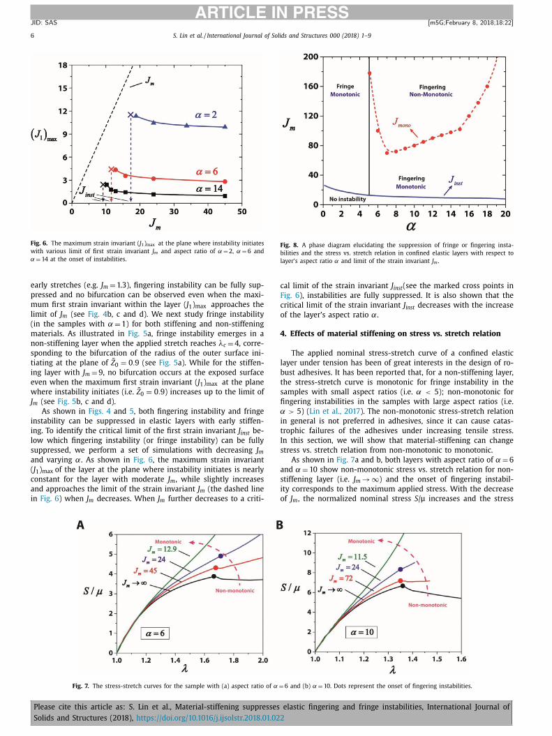
6
b
s. stretch relation transits from non-monotonic to monotonic in
oth layers. For the layer which stiffens at moderate stretches
e.g. J m
= 24 and J m
= 45 for α = 6, J m
= 24 and J m
= 72 for α = 10),
he onset of fingering instability is corresponding to a kink of
he stress-stretch curve while the stress keeps increasing. For the
ayers with early stiffening (e.g J m
= 12.9 for α = 6, J m
= 11.5 for
= 10), instabilities are shown to be fully suppressed and stress
onotonically increases with the applied stretch. The transition of
he stress vs. stretch relations from non-monotonic to monotonic
ives the other critical limit of the strain invariant J mono , below
hich the tensile stress vs. stretch relation of a confined layer is
onotonic. As shown in Fig. 8 , we summarize J mono for the layers
ith the aspect ratio from 5 to 20.
. Phase diagram for the suppression of instabilities in
onfined layers
In Section 3 , we first identify the critical aspect ratio between
ringe instability and fingering instability αfringe − fingering and we
urther show the critical limit of first strain invariant J inst below
hich both fringe instability and fingering instability are fully sup-
ressed. In Section 4 , we identify the other critical limit of first
Please cite this article as: S. Lin et al., Material-stiffening suppresses
Solids and Structures (2018), https://doi.org/10.1016/j.ijsolstr.2018.01.022
train invariant J mono , below which the tensile stress vs. stretch re-
ation of a confined layer is monotonic. In this section, we summa-
ize the results in previous sections and further construct a phase
iagram in the plot of aspect ratio α and limit of the strain in-
ariant J m
, elucidating the effect of material-stiffening on selection
f modes and suppression of both fringe and fingering instabilities.
s shown in Fig. 8 , for a layer with early stiffening (i.e. J m
< J inst ),
here is no fringe instability or fingering instability setting in. For
layer with moderate stiffening (i.e. J inst < J m
< J mono ), undula-
ions can initiate at the exposed surface of the layer and the ap-
lied stress monotonically increases with the applied stretch. For a
ayer which shows negligible stiffening (i.e. J m
> J mono ), the stress
s. stretch relation applied on the layer is non-monotonic and the
nset of the instability (i.e. fingering instability) is correlated with
he point of maximum stress. The phase diagram can serve as a
uideline on selection of the mode of instability and monotonicity
f stress vs. stretch relation.
. Experimental validations
To validate the suppression of both fringe and fingering insta-
ilities in experiment, we chose Ecoflex rubber and Polyacrylamide
elastic fingering and fringe instabilities, International Journal of
S. Lin et al. / International Journal of Solids and Structures 0 0 0 (2018) 1–9 9
ARTICLE IN PRESS
JID: SAS [m5G; February 8, 2018;18:22 ]
1
λ
p
r
i
A
e
D
i
i
s
e
b
t
r
b
o
a
w
f
a
A
w
ζ
C
b
e
w
i
t
s
a
u
R
B
B
C
C
C
D
G
H
L
L
L
L
L
M
S
S
S
S
T
W
Y
Y
Y
Z
The incompressibility of the elastic layer is enforced by det F = , which implies:
zZ A
′ 1 u 1 + λzZ
A 2 ω + A 1
R
u 1 − γrZ A
′ 3 u 2 + λrR A 3 u
′ 2 = 0 . (A7)
The perturbation in deformation gradient will further induce a
erturbation in nominal stress which results in the nominal stress
eading as S /μ = (S ) 0 /μ + ε ̃ S . Here, ˜ S is the perturbed normal-
zed nominal stress writing as ˜ S = Grad ̃ x +
1 ε [ ( ̄p )
0 (F ) 0 −T − p̄ F −T ] .
balance of the forces exerted on an element of the perturbed
lastomer further leads to three equations of equilibrium through
iv ̃ S = 0 . The four unknown A i ( i = 1, 2, 3, 4) can be fully spec-
fied by these three equations and the incompressibility condition
n Eq. (A7) with boundary conditions that the traction t R = S · e R hall be zero at R̄ = 1 . The four equations can be simplified by
liminating A 2 and A 4 . Furthermore, we notice that fingering insta-
ility is an instability mode with A 3 = 0 and fringe instability with
he layer’s aspect ratio slightly smaller than the transition aspect
atio αfringe − fingering between fingering instability and fringe insta-
ility is an instability mode with A 3 �A 1 and A 3 �A 2 . Therefore, the
nly governing ODE to be solved is with respect to the amplitude
long radius direction A 1 in the dimensionless form, reading:
R̄
4 A
(4) 1
+ 6 ̄R
3 A
(3) 1
+ ( 5 − 2 ω
2 ) ̄R
2 A
′′ 1 − ( 2 ω
2 + 1 ) ̄R A
′ 1
+ ( ω
2 − 1 ) 2 A 1 − A
2 h R̄
2 [ ̄R
2 A
′′ 1 + 3 ̄R A
′ 1 − ( ω
2 − 1 ) A 1 ] = 0 , (A8)
ith A h =
√
κ2 α2
1 −λrR . By setting the boundary conditions of traction
ree at R̄ = 1 , namely ˜ S rR = 0 , ˜ S θR = 0 and
˜ S zR = 0 , the two bound-
ry conditions in the dimensionless form read as:
A
(3) 1
(1) + 4 A
′′ 1 (1) + [ 1 − 2 ω
2 − ζω
2 − A
2 h ] A
′ 1 (1)
+[ ω
2 − 1 + ω
2 κ2 α2 − A
2 h ] A 1 (1) = 0 , (A9a)
′′ 1 (1) + ( 2 − ζ ) A
′ 1 (1) + ζ
(ω
2 − 1
)A 1 (1) = 0 , (A9b)
ith
( ̄Z 0 ) =
1
2
κ2 α2 +
1
2
λ−6 rR + C 3 λ
−2 rR , (A9c)
3 =
1
cos 2 κ
[ 1 − 1
2
κ2 α2 ]
− 1
2
cos 4 κ. (A9d)
The existence of the non-trivial solution for Eq. (A8) with two
oundary conditions in Eq. (A9) depends on whether the following
quation has solution or not: (l 2 ω
3 A h + lA
3 h − l 2 ω A h
) I ω−1 ( A h )
I ω ( A h )
−(2 l ω
2 A
2 h + 2 l 2 ω
4 − 2 l 2 ω
2 + A
4 h
)+
(2 l ω
2 + ωA
2 h − lω A h
I ω−1 ( A h )
I ω ( A h )
)κ2 α2 = 0 (A10)
here l = 1 + ζ .
Please cite this article as: S. Lin et al., Material-stiffening suppresses
Solids and Structures (2018), https://doi.org/10.1016/j.ijsolstr.2018.01.022
By minimizing κ through ω at each plane, we can have the crit-
cal stretch λc , the critical number of undulations ω c and the ver-
ical location of the plane where the undulations initiate Z 0 . As
hown in Fig. 3 , the theoretical results for the critical stretch λc
nd the critical number of undulations ω c are compared with sim-
lation results, showing good agreement.
eferences
enjamin, M. , Toumi, H. , Ralphs, J. , Bydder, G. , Best, T. , Milz, S. , 2006. Where tendonsand ligaments meet bone: attachment sites (‘entheses’) in relation to exercise
and/or mechanical load. J. Anat. 208, 471–490 .
iggins, J.S. , Saintyves, B. , Wei, Z. , Bouchaud, E. , Mahadevan, L. , 2013. Digital insta-bility of a confined elastic meniscus. Proc. Natl. Acad. Sci. 110, 12545–12548 .
haudhury, M.K. , Chakrabarti, A . , Ghatak, A . , 2015. Adhesion-induced instabilitiesand pattern formation in thin films of elastomers and gels. Eur. Phys. J. E 38,
1–26 . reton, C. , Ciccotti, M. , 2016. Fracture and adhesion of soft materials: a review. Rep.
Prog. Phys. 79, 046601 . rosby, A.J. , Shull, K.R. , Lakrout, H. , Creton, C. , 20 0 0. Deformation and failure modes
of adhesively bonded elastic layers. J. Appl. Phys. 88, 2956–2966 .
ent, A. , 1996. A new constitutive relation for rubber. Rubber Chem. Technol. 69,59–61 .
uang, Y. , King, D.R. , Sun, T.L. , Nonoyama, T. , Kurokawa, T. , Nakajima, T. , Gong, J.P. ,2017. Energy-dissipative matrices enable synergistic toughening in fiber rein-
forced soft composites. Adv. Funct. Mater .
in, S. , Cao, C. , Wang, Q. , Gonzalez, M. , Dolbow, J.E. , Zhao, X. , 2014a. Design of stiff,tough and stretchy hydrogel composites via nanoscale hybrid crosslinking and
macroscale fiber reinforcement. Soft Matter 10, 7519–7527 . in, S. , Cohen, T. , Zhang, T. , Yuk, H. , Abeyaratne, R. , Zhao, X. , 2016. Fringe instability
in constrained soft elastic layers. Soft Matter 12, 8899–8906 . in, S. , Mao, Y. , Radovitzky, R. , Zhao, X. , 2017. Instabilities in confined elastic layers
under tension: fringe, fingering and cavitation. J. Mech. Phys. Solids .
in, S. , Zhou, Y. , Zhao, X. , 2014b. Designing extremely resilient and tough hydrogelsvia delayed dissipation. Extreme Mech. Lett. 1, 70–75 .
iu, X. , Tang, T.-C. , Tham, E. , Yuk, H. , Lin, S. , Lu, T.K. , Zhao, X. , 2017. Stretchable livingmaterials and devices with hydrogel–elastomer hybrids hosting programmed
cells. Proc. Natl. Acad. Sci. 114, 2200–2205 . otte, S. , Kaufman, L.J. , 2013. Strain stiffening in collagen I networks. Biopolymers
99, 35–46 .
harma, A. , Licup, A. , Jansen, K. , Rens, R. , Sheinman, M. , Koenderink, G. , MacKin-tosh, F. , 2016. Strain-controlled criticality governs the nonlinear mechanics of
fibre networks. Nat. Phys . hull, K.R. , 2002. Contact mechanics and the adhesion of soft solids. Mater. Sci. Eng.
ummala, G.K. , Joffre, T. , Rojas, R. , Persson, C. , Mihranyan, A. , 2017. Strain-inducedstiffening of nanocellulose-reinforced poly (vinyl alcohol) hydrogels mimicking
collagenous soft tissues. Soft Matter 13, 3936–3945 . aite, J.H. , Andersen, N.H. , Jewhurst, S. , Sun, C. , 2005. Mussel adhesion: finding the
tricks worth mimicking. J. Adhes. 81, 297–317 .
uk, H. , Lin, S. , Ma, C. , Takaffoli, M. , Fang, N.X. , Zhao, X. , 2017. Hydraulic hydrogel ac-tuators and robots optically and sonically camouflaged in water. Nat. Commun.
8 . uk, H. , Zhang, T. , Lin, S. , Parada, G.A. , Zhao, X. , 2016a. Tough bonding of hydrogels
to diverse non-porous surfaces. Nat. Mater. 15, 190–196 . uk, H. , Zhang, T. , Parada, G.A. , Liu, X. , Zhao, X. , 2016b. Skin-inspired hydrogel-elas-
tomer hybrids with robust interfaces and functional microstructures. Nat. Com-mun. 7 .
hao, B. , Zeng, H. , Tian, Y. , Israelachvili, J. , 2006. Adhesion and detachment mecha-
nisms of sugar surfaces from the solid (glassy) to liquid (viscous) states. Proc.Natl. Acad. Sci. 103, 19624–19629 .
elastic fingering and fringe instabilities, International Journal of