Dynamic measuring systems for liquids other than water. Part 2: Metrological controls and performance tests Ensembles de mesurage dynamique de liquides autres que l’eau. Partie 2: Contrôles métrologiques et essais de performance OIML R 117-2 Edition 2014 (E) OIML R 117-2 Edition 2014 (E) ORGANISATION INTERNATIONALE DE MÉTROLOGIE LÉGALE INTERNATIONAL ORGANIZATION OF LEGAL METROLOGY INTERNATIONAL RECOMMENDATION
Transcript
Dynamic measuring systems for liquids other than water.
Part 2: Metrological controls and performance tests
Ensembles de mesurage dynamique de liquides autres que l’eau.
Partie 2: Contrôles métrologiques et essais de performance
2 Metrological control .................................................................................................................. 8 2.1 Type evaluation and approval .......................................................................................................................... 8 2.2 Initial verification ............................................................................................................................................ 9
3 Symbols, units and equations ................................................................................................. 10
4 Type evaluation performance tests ........................................................................................ 14 4.1 General .......................................................................................................................................................... 14 4.2 Measurement uncertainty .............................................................................................................................. 14 4.3 Reference conditions ..................................................................................................................................... 15 4.4 Test quantities ................................................................................................................................................ 15 4.5 Preventing the liquid temperature from influencing test results .................................................................... 15 4.6 Software setting / configuration..................................................................................................................... 15 4.7 Reverse flow .................................................................................................................................................. 15 4.8 Disturbance and influence factor tests - climatic and mechanical environmental conditions ........................ 16 4.9 Disturbance and influence factor tests – electrical tests ................................................................................ 23 4.10 Tests for EUTs powered by a road vehicle battery ........................................................................................ 39
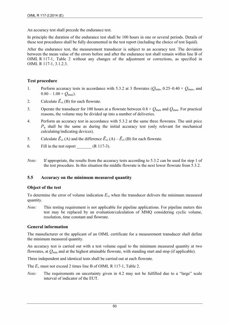
5 Testing procedures for meter sensors and measuring devices ............................................ 43 5.1 General information ....................................................................................................................................... 43 5.2 Test equipment .............................................................................................................................................. 45 5.3 Accuracy ........................................................................................................................................................ 46 5.4 Endurance test ............................................................................................................................................... 49 5.5 Accuracy on the minimum measured quantity .............................................................................................. 50 5.6 Additional testing procedures for electronic measuring devices (sensor + transducer) ................................. 51
6 Testing procedures for electronic calculators (that may be equipped with a conversion device), indicating devices, and associated devices ........................................... 53
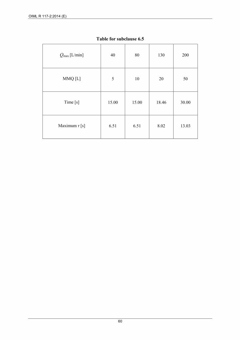
6.1 General information ....................................................................................................................................... 53 6.2 Electronic calculators and indicating devices ................................................................................................ 55 6.3 Conversion device (as part of an electronic calculator) ................................................................................. 56 6.4 Associated measuring devices ....................................................................................................................... 58 6.5 Temperature conversion: Tests on the response time of the measuring system temperature sensor ............. 59
7 Testing procedures for gas elimination devices .................................................................... 61 7.1 General information ....................................................................................................................................... 61 7.2 Testing ........................................................................................................................................................... 62
8 Testing procedures for ancillary devices .............................................................................. 73 8.1 General information ....................................................................................................................................... 73 8.2 Disturbance and influence factor tests for ancillary devices .......................................................................... 74 8.3 Printing devices ............................................................................................................................................. 75 8.4 Memory devices ............................................................................................................................................ 76 8.5 Conversion devices ........................................................................................................................................ 77
OIML R 117-2:2014 (E)
4
Annex A Testing procedures for fuel dispensers (type evaluation) ...................................................... 78 A.1 General information ....................................................................................................................................... 78 A.2 Testing procedures for meters ....................................................................................................................... 78 A.3 Testing procedures for electronic devices: calculator, correction, indicating and associated devices ........... 78 A.4 Testing procedures for gas elimination .......................................................................................................... 79 A.5 Testing procedures for ancillary devices ....................................................................................................... 79 A.6 Additional testing procedures for complete fuel dispensers .......................................................................... 79
Annex A-LPG Testing procedures for LPG dispensers (type evaluation) ........................................... 83 A-LPG.1 General information ........................................................................................................................... 83 A-LPG.2 Testing procedures for meters ............................................................................................................ 83 A-LPG.3 Testing procedures for electronic devices: calculator, correction, indicating, and associated
devices ................................................................................................................................................ 84 A-LPG.4 Testing procedures for gas elimination .............................................................................................. 84 A-LPG.5 Testing procedures for ancillary devices ............................................................................................ 84 A-LPG.6 Additional testing procedures for complete LPG dispensers ............................................................. 85
Annex B Testing procedures for measuring systems on road tankers ................................................. 89
B.1 General information ....................................................................................................................................... 89 B.2 Metrological controls and performance tests for type evaluation of the constituent elements ...................... 89 B.3 Metrological controls and performance tests of the complete measuring system .......................................... 90
Annex E Testing procedures for measuring systems for milk, beer and other foaming potable liquids ......................................................................................................................... 94
E.1 General information ....................................................................................................................................... 94 E.2 Tests for meter sensors, measuring devices and meters with mechanical indicating devices ........................ 94 E.3 Tests for electronic devices (calculator, correction device, indicating device, associated devices) .............. 95 E.4 Tests for air/gas elimination devices ............................................................................................................. 96 E.5 Tests for ancillary devices ............................................................................................................................. 97 E.6 Additional tests on the complete measuring systems .................................................................................... 97 E.7 Hose variation .............................................................................................................................................. 113
Annex F Testing procedures for measuring systems on pipelines and systems for the loading of ships ...................................................................................................................... 114
F.1 General information ..................................................................................................................................... 114 F.2 Metrological controls and performance tests for type evaluation ................................................................ 115
Annex G Testing procedures for measuring systems for the fueling of aircraft ............................. 116 G.1 General information ..................................................................................................................................... 116 G.2 Metrological controls and performance tests for type evaluation ................................................................ 116
Annex X Interpretation, examples, advice, and possible solutions ................................................... 119
X.2 Advice annex on clause 2 “Metrological control” ....................................................................................... 119 X.5 Advice annex on clause 5 “Testing procedures for meter sensors and measuring devices” ........................ 123 X.7 Advice annex on clause 7 “Test procedures for gas elimination devices”................................................... 127 X.A Advice annex on Annex A “Testing procedures for fuel dispensers (type evaluation)” ............................. 132 X.A-I Advice annex - Draft testing procedures for fuel dispensers (for initial verification) ............................ 136 X.A-LPG-I Advice annex - Draft testing procedures for LPG dispensers (for initial verification) ..................... 147 X.E Advice annex on Annex E “Testing procedures for measuring systems for milk, beer and
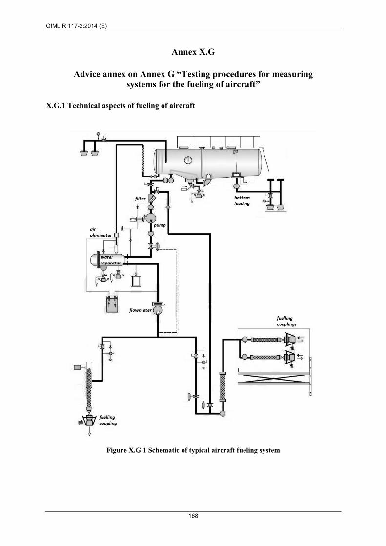
other foaming potable liquids” .................................................................................................................... 158 X.G Advice annex on Annex G “Testing procedures for measuring systems for the fueling of aircraft” ........... 168
OIML R 117-2:2014 (E)
5
OIML R 117-2 Annex List Test procedures for complete measuring systems
A and
A-LPG
Annex A Fuel dispensers Blend dispensers ----------------------------------------------------------- Annex A-LPG Fuel dispensers for liquefied gases under
pressure (LPG dispensers)
B Measuring systems on road tankers
C* Measuring systems for the unloading of ships' tanks and for rail and road tankers using an intermediate tank
D* Measuring systems for liquefied gases under pressure (other than LPG dispensers)
E Measuring systems for milk, beer, and other foaming potable liquids
F Measuring systems on pipelines and systems for loading ships
G Measuring systems intended for the fueling of aircraft
H* Self-service arrangements with fuel dispensers
I* Other self-service arrangements
J* Unattended delivery
K* Measuring systems for bunker fuel (to be added later)
L* Measuring systems for liquefied natural gas (LNG) (to be added later)
X Annex of advice and suggested practices
* At the time of publication, these Annexes are under development. It is planned to add them in a future revision of this Recommendation.
OIML R 117-2:2014 (E)
6
Foreword
The International Organization of Legal Metrology (OIML) is a worldwide, intergovernmental organization whose primary aim is to harmonize the regulations and metrological controls applied by the national metrological services, or related organizations, of its Member States. The main categories of OIML publications are:
• International Recommendations (OIML R), which are model regulations that establish the metrological characteristics required of certain measuring instruments and which specify methods and equipment for checking their conformity. OIML Member States shall implement these Recommendations to the greatest possible extent;
• International Documents (OIML D), which are informative in nature and which are intended to harmonize and improve work in the field of legal metrology;
• International Guides (OIML G), which are also informative in nature and which are intended to give guidelines for the application of certain requirements to legal metrology;
• International Basic Publications (OIML B), which define the operating rules of the various OIML structures and systems; and
OIML Draft Recommendations, Documents and Guides are developed by Project Groups linked to Technical Committees or Subcommittees which comprise representatives from OIML Member States. Certain international and regional institutions also participate on a consultation basis. Cooperative agreements have been established between the OIML and certain institutions, such as ISO and the IEC, with the objective of avoiding contradictory requirements. Consequently, manufacturers and users of measuring instruments, test laboratories, etc. may simultaneously apply OIML publications and those of other institutions.
International Recommendations, Documents, Guides and Basic Publications are published in English (E) and translated into French (F) and are subject to periodic revision.
Additionally, the OIML publishes or participates in the publication of Vocabularies (OIML V) and periodically commissions legal metrology experts to write Expert Reports (OIML E). Expert Reports are intended to provide information and advice, and are written solely from the viewpoint of their author, without the involvement of a Technical Committee or Subcommittee, nor that of the CIML. Thus, they do not necessarily represent the views of the OIML.
This publication, OIML R 117-2, edition 2014 (E) – was developed by Project Group 2 of OIML TC 8/SC 3 Dynamic measurement of liquids other than water. It was approved for final publication by the International Committee of Legal Metrology in 2014 and will be submitted to the International Conference on Legal Metrology in 2016 for formal sanction.
OIML Publications may be downloaded from the OIML web site in the form of PDF files. Additional information on OIML Publications may be obtained from the Organization’s headquarters:
Bureau International de Métrologie Légale 11, rue Turgot - 75009 Paris - France Telephone: 33 (0)1 48 78 12 82 Fax: 33 (0)1 42 82 17 27 E-mail: [email protected] Internet: www.oiml.org
OIML R 117-2:2014 (E)
7
Dynamic measuring systems for liquids other than water
Part 2: Metrological controls and performance tests
1 Scope 1.1 This Recommendation specifies the metrological and technical requirements applicable to dynamic measuring systems for quantities (volume or mass) of liquids other than water subject to legal metrology controls. It also provides requirements for the approval of specific components of the measuring systems (meter, electronic calculator, etc.).
1.2 In principle, this Recommendation applies to all measuring systems fitted with a meter as defined in T.m.3 (continuous measurement), whatever be the measuring principle of the meters or their application, except
• dynamic measuring devices and systems for cryogenic liquids (OIML R 81),
• water meters for the metering of cold potable water and hot water (OIML R 49-1, R 49-2 and R 49-3), and
• heat meters (OIML R 75-1, R 75-2 and R 75-3).
1.3 This Recommendation is not intended to prevent the development of new technologies.
1.4 National or international regulations are expected to clearly specify which measuring systems for liquids other than water are subject to legal metrology controls. For waste water measurement, it is up to the national authorities to decide whether the use of measuring systems conforming to this Recommendation is mandatory, and which accuracy class is required.
1.5 Part 2 of this Recommendation (OIML R 117-2) specifies the metrological controls and performance tests to meet the metrological and technical requirements of OIML R 117-1 for
• the type evaluation of complete measuring systems, and
• the type evaluation of constituent elements of a measuring system that are approved for separate type approval.
OIML R 117-2:2014 (E)
8
2 Metrological control
2.1 Type evaluation and approval Measuring systems subject to legal metrology control shall be subject to type evaluation and approval.
In addition, the constituent elements of a measuring system, mainly those listed below, and the sub-systems which include several of these elements (for example, a flowcomputer), are able to receive separate type approval upon the request of the manufacturer:
• meter; • measuring device; • meter sensor; • transducer; • calculator/electronic calculator; • indicating device; • gas separator; • gas extractor; • special gas extractor; • conversion device; • ancillary devices providing or memorizing measurements results: • printing device; • memory device; • self-service device; • temperature measuring device or sensor; • pressure measuring device or sensor; • density measuring device or sensor.
See also Annex X.2.1 for the chart “General metrological requirements for specific components of a measuring system” which shows the components that are able to receive a separate type approval cross-referenced with clauses from OIML R 117-1 that apply to each component.
Note: In some countries, the expressions “type evaluation” and “type approval” can be reserved for complete measuring systems. In this case, it is advisable that types of constituent elements be submitted to a procedure similar to type evaluation, making it possible to certify the conformity of the type of a constituent element to the regulation.
The constituent elements of a measuring system shall comply with the relevant requirements even when they have not been subject to separate type evaluation (except in the case of ancillary devices and additional devices that are exempted from the controls).
Unless otherwise specified in this Recommendation, a measuring system shall fulfil the requirements without adjustment of the system or of its elements during the course of the tests. Relevant tests belonging together should be carried out on the same measuring system or element, under the same conditions and without adjustment. If, however, an adjustment has been performed or tests have been conducted with another measuring system and/or device this shall be documented and justified in the test report.
Any exceptions to the test procedures described in OIML R 117-2 shall be fully and clearly documented in the type evaluation report.
OIML R 117-2:2014 (E)
9
2.2 Initial verification Measuring systems subject to legal metrology control shall be subject to initial verification.
The object of the initial verification is to verify the compliance of complete measuring systems with the requirements described in OIML R 117-1, 6.2 and ensure the systems conform to their approved type before they are placed into service.
Note: Some of the draft initial verification test procedures for complete measuring systems can be found in Annex X (Advice and suggested practices). Initial verification test procedures will be added in the immediate revision of all three parts of OIML R 117.
OIML R 117-2:2014 (E)
10
3 Symbols, units and equations In this Recommendation the following symbols, units and equations are used:
CID Calculator and indicating device
NCU National currency unit
EUT Equipment under test
MPE Maximum permissible error
RH Relative humidity
e Scale interval (L, kg) of the main indicating device
f Frequency of pulses sent to the CID (pulses per second)
i Number of pulses sent to the CID
K Variable determined by the ratio Qmin/Qmax and the number of flowrates for accuracy testing
MMQ Minimum measured quantity (L or kg - see also Vmin)
nF Sequence number of a flowrate test
NF Number of flowrates for accuracy testing
Pu Indicated unit price (NCU/L, NCU/kg)
pt Pressure of the liquid passing through the meter or the measurement transducer (bar)
pmin Minimum pressure of the liquid passing through the meter or the measurement transducer (bar)
pmax Maximum pressure of the liquid passing through the meter or the measurement transducer (bar)
μ Dynamic viscosity of the liquid (mPa∙s)
Qs Simulated flowrate of the liquid (L/min, kg/min)
Q Flowrate of liquid (L/min, kg/min)
Qmin Minimum flowrate of liquid (L/min, kg/min)
Qmax Maximum flowrate of liquid (L/min, kg/min)
Qa Flowrate of air (L/min, kg/min)
t Time (s)
Ts Temperature of the liquid in the standard capacity measure (ºC)
Tr Reference temperature of the standard capacity measure (ºC)
Tt Temperature of the liquid passing through the meter or measurement transducer (ºC)
U Expanded uncertainty
max1 QKQ Fn ×= −
11
max
min−
=
FN
QQK
OIML R 117-2:2014 (E)
11
Vmin Minimum measured quantity - volume (L)
Vi Indicated volume at metering conditions by the CID (L)
Vs Volume indication of the standard capacity measure (L)
Vr Volume indication of the standard capacity measure, compensated from the deviation of the reference temperature (L)
Vm Volume at metering conditions stored by the CID if the CID is fitted with a memory device (L)
Vp Printed volume at metering conditions if the CID is fitted with a printing device (L)
Vc Volume at metering conditions calculated from the number of simulated pulses i and the k-factor kf (L)
Vn Volume at metering conditions (L) passing through the meter compensated for deviation from reference temperature of the standard capacity measure and pressure and temperature of the liquid
Va Volume of air (L)
Mi Indicated mass CID (kg)
Ms Mass indication of the weighing instrument (kg)
Mb Mass indication of the weighing instrument, corrected for the buoyancy (kg)
Mm Indicated mass stored by the CID if the CID is fitted with a memory device (kg)
Mp Printed mass if the CID is fitted with a printing device (kg)
Mc Mass calculated from the number of simulated pulses i and the k-factor kf (kg)
kf k-factor, number of pulses per unit of quantity (pulses/L, pulses/kg)
α Cubic expansion coefficient of the test liquid due to temperature (ºC-1)
χ Compressibility coefficient of the test liquid (bar-1)
β Cubic expansion coefficient of the standard capacity measure due to temperature (ºC-1)
OIML R 117-2:2014 (E)
12
Notes: For the determination of α refer to OIML R 63 or ISO 91-1 for petroleum products.
For the determination of χ refer to the API Manual of Petroleum Measurements Standards Chapter 11.2.1 for petroleum products (new fuels issues, including E10).
If β is not known, the following values can be used.
Material β (ºC-1)
(uncertainty: 5 × 10⁻⁶ ºC -1)
Borosilica glass 10 × 10-6
Glass 27 × 10-6
Mild steel 33 × 10-6
Stainless steel 51 × 10-6
Copper, brass 53 × 10-6
Aluminium 69 × 10-6
Pi Indicated price (price to pay) by the CID (NCU)
Pm Price stored by the CID if the CID is fitted with a memory device (NCU)
Pp Printed price if the CID is fitted with a printing device (NCU)
Pc Calculated price (NCU)
Evi Error of indicated volume at metering conditions (%)
Evm Error of stored volume at metering conditions if the CID is fitted with a memory device (%)
Evp Error of printed volume at metering conditions if the CID is fitted with a printing device (%)
Eva Error of indicated volume at metering conditions resulting of the presence of air (%)
Emi Error of indicated mass (%)
Emm Error of stored mass if the CID is fitted with a memory device (%)
Emp Error of printed mass if the CID is fitted with a printing device (%)
Ema Error of indicated mass resulting from the presence of air (%)
ε0 Intrinsic error of the instrument at metering conditions (%)
ε1 Intrinsic error at metering conditions obtained at the first accuracy test (%)
ε2 Intrinsic error at metering conditions obtained at the second accuracy test (%)
ε3 Intrinsic error at metering conditions obtained at the third accuracy test (%)
Evi(B) Error of indicated volume at metering conditions before the endurance test (%)
Evi(A) Error of indicated volume at metering conditions after the endurance test (%)
Emi(B) Error of indicated mass at metering conditions before the endurance test (%)
Emi(A) Error of indicated mass at metering conditions after the endurance test (%)
OIML R 117-2:2014 (E)
13
Epi Error of indicated price (NCU)
Epm Error of stored price if the CID is fitted with a memory device (NCU)
Epp Error of printed price if the CID is fitted with a printing device (NCU)
Ē Mean value of errors (%, NCU, ºC, bar)
n Number of tests at the same condition
Qs = 60 × i / (kf × t) Vc = i / kf
Mc = i / kf
Pc = Vi × Pu, Mi × Pu
Vr = Vs × [1 + β (Ts – Tr)]
Vn = Vr × [1 + α(Tt – Ts)] × [1 – χ pt]
Evi = [(Vi – Vc) / Vc] × 100 Vc may be replaced by Vr or Vn, if appropriate
Evm = [(Vm – Vc) / Vc] × 100 Vc may be replaced by Vr or Vn, if appropriate
Evp = [(Vp – Vc) / Vc] × 100 Vc may be replaced by Vr or Vn, if appropriate
Eva = [(Vi – Vc) / Vc ] × 100 Vc may be replaced by Vr or Vn, if appropriate
Emi = [(Mi – Mc) / Mc] × 100 Mc may be replaced by Mb, if appropriate
Emm = [(Mm – Mc) / Mc] × 100 Mc may be replaced by Mb, if appropriate
Emp = [(Mp – Mc) / Mc] × 100 Mc may be replaced by Mb, if appropriate
Ema = [(Mi – Mc) / Mc] × 100 Mc may be replaced by Mb, if appropriate
Epi = Pi – Pc
Epm = Pm – Pc
Epp = Pp – Pc
Ē = [E(1) + E(2) + ... + E(n)] / n
εv1 = [(Vi – Vc) / Vc]1 × 100 Vc may be replaced by Vr or Vn, if appropriate
εv2 = [(Vi – Vc) / Vc]2 × 100 Vc may be replaced by Vr or Vn, if appropriate
εv3 = [(Vi – Vc) / Vc]3 × 100 Vc may be replaced by Vr or Vn, if appropriate
εm1 = [(Mi – Mc) / Mc]1 × 100 Mc may be replaced by Mb, if appropriate
εm2 = [(Mi – Mc) / Mc]2 × 100 Mc may be replaced by Mb, if appropriate
εm3 = [(Mi – Mc) / Mc]3 × 100 Mc may be replaced by Mb, if appropriate
ε0 = [ε1 +ε2 + ε3 ] / 3
Range = Maximum error – minimum error (%, NCU)
OIML R 117-2:2014 (E)
14
4 Type evaluation performance tests
4.1 General This set of performance tests is intended to verify that the measuring system or its constituent elements operate as intended in a specified environment and under specified conditions. Each test indicates, where appropriate, the reference conditions for determining the intrinsic error.
Different kinds of tests are specified:
• accuracy tests (including repeatability and flow disturbances tests, if applicable);
• influence factor tests; and
• disturbance tests.
The tests specified in this Recommendation are considered to be sufficient test procedures to meet the requirements of OIML R 117-1. However, for new technologies or new applications, additional tests may be necessary to ensure compliance of the measuring system or its constituent elements with the requirements of this Recommendation.
When the effect of one influence quantity is being evaluated, all other influence quantities shall be held relatively constant, at values close to reference conditions.
More recent versions of the specific IEC and ISO standards referenced in this chapter’s performance tests may be applied as long as the authority performing the type evaluation (the testing laboratory) confirms that the more recent versions continue to cover the testing requirements in this Recommendation.
Tests are ideally carried out on the complete measuring system, fitted with an indicating device, with all the ancillary devices, and with the correction device, if any. However, the meter subject to testing is not required to be fitted with its ancillary devices when the latter are not likely to influence the accuracy of the meter and when these have been verified separately (for example, an electronic printing device). The measuring device may also be tested separately provided that the calculator and the indicating device have been verified. The meter sensor may be tested separately provided that the transducer and the calculator with indicating device have been verified.
If this measuring device or meter sensor is intended to be connected to a calculator fitted with a correction device, the applicable correction algorithm(s) provided by the manufacturer shall be applied on the output signal of the transducer in order to determine its error.
4.2 Measurement uncertainty
4.2.1 When a test is conducted, the expanded uncertainty of the determination of errors on indications of volume or mass shall be less than one-fifth of the maximum permissible error applicable for that test during type evaluation and one-third of the maximum permissible error applicable for that test during other verifications. The expanded uncertainty is calculated according to the “Guide to the expression of uncertainty in measurement” (2008 edition) with k = 2. In the calculation of the uncertainty, the resolution of the EUT shall be taken into account.
4.2.2 It is always preferable to apply 4.2.1. However, if it is technically or economically impractical to reach an uncertainty of 1/5 and 1/3 of the MPE, a “reduced MPE = (6/5 × MPE – U)” and a “reduced MPE = (4/3 × MPE – U)” respectively may be used. When calculating the expanded uncertainty, the resolution but not the repeatability of the EUT shall be included. This exception is only valid in the case of mutual agreement of the manufacturer and the test authority. Use of this exception shall be fully documented.
OIML R 117-2:2014 (E)
15
4.3 Reference conditions Ambient temperature: 15 ºC to 35 ºC
Relative humidity: 25 % to 75 %
Atmospheric pressure: 84 kPa to 106 kPa
Mains (power supply) voltage: Nominal voltage (Unom)
Mains (power supply) frequency: Nominal frequency (fnom)
During each test, the temperature shall not vary by more than 5 ºC and the relative humidity shall not vary by more than 10 % within the reference range.
The test laboratory shall have the ability to authorize different reference conditions as long as these conditions are fully documented with an explanation of why the alternate reference conditions were used, the implications of the alternate reference conditions, and the effects on the testing results.
4.4 Test quantities Some influence quantities have a systematic (absolute) effect on measurement results and not a proportional effect related to the measured volume. If the fault limit is related to the measured volume (in order to be able to compare results obtained in different laboratories), it is necessary to perform a test on a fixed volume and flowrate, and not less than the minimum measured quantity. Furthermore, the test volume shall be in accordance with the uncertainty requirements in 4.2.
Note: In this subclause, “fault limit” is the value that determines when a fault is a significant fault.
4.5 Preventing the liquid temperature from influencing test results Temperature tests concern testing the effect of the ambient temperature on the measurement result and not the effect of the temperature of the applied liquid. Simulation of the flow signal while performing the test is advisable in order to prevent the temperature of the liquid from influencing the test results. These test methods for evaluating the influence of the ambient temperature are presented in 4.8.
4.6 Software setting / configuration Software is a critical factor in the proper operation of a measuring system. Therefore, it must be verified that the software is configured correctly, and that the type approval certificate includes any restriction in parameter setting/configuration.
4.7 Reverse flow Check if a reversal of the flow results in an error greater than the minimum specified quantity deviation. If so, the measuring system (in which the liquid could flow in the opposite direction) shall be provided with a non-return valve. See also the flow computers clause and OIML R 117-1, 2.13.4.
Note 1: See 5 for “Testing procedures for meter sensors and measuring devices”.
Note 2: See 6 for “Testing procedures for electronic calculators (that may be equipped with a conversion device), indicating devices and associated devices”.
OIML R 117-2:2014 (E)
16
4.8 Disturbance and influence factor tests - climatic and mechanical environmental conditions
4.8.1 General
The general reference for testing requirements in 4.8 is OIML D 11:2013.
The test procedures in 4.8 have been given in condensed form, for information only, and are adapted from the referenced IEC and ISO publications. Before conducting the tests, the applicable publications should be consulted.
4.8.1.1 For each performance test, typical test conditions are indicated; these conditions correspond to the climatic and mechanical environmental conditions to which measuring systems are usually exposed.
4.8.1.2 The applicant for type evaluation shall specify the rated operating conditions and the specific environmental conditions in the documentation supplied to the authority performing the type evaluation (the testing laboratory) based on the intended use of the instrument. Higher severity levels may be requested by the manufacturer. The authority performing the type evaluation (the testing laboratory) shall conduct performance tests at the agreed severity levels. If type approval is granted, the data plate on the EUT shall indicate the corresponding limits of use. Manufacturers shall inform potential users of the environmental conditions for which the instrument is approved. The authority performing the type evaluation (the testing laboratory) shall verify that these environmental conditions are met.
4.8.2 Test levels for temperature
The thermal conditions in which measuring systems and ancillary devices are used vary considerably. These are not only highly dependent on the place on earth, ranging from arctic to tropical regions, but are also considerably dependent on indoor or outdoor applications. Devices typically used indoors in one country can be typically used outdoors in other countries. Therefore, no classes combining low and high temperature limits have been described in this Recommendation.
Note: While manufacturers select the test levels for type evaluation, national (or regional) legislation will generally set the requirements for acceptable lower and upper temperature limits (taking into account the test levels in 4.8.5 and 4.8.6).
OIML R 117-2:2014 (E)
17
4.8.3 Classification for humidity
The following table gives a classification for the test levels (severity levels) for the humidity tests:
Class Test level
Damp heat (cyclic)
Description
H1 -
This class applies to instruments or parts of instruments typically used in temperature-controlled enclosed (weather-protected) locations. Where necessary, heating, cooling or humidification is used to maintain the required environmental conditions. Measuring instruments are not exposed to condensed water, precipitation, or ice formations.
These conditions may apply in living areas, continuously staffed offices, certain workshops, and other rooms for special applications.
H2 1
This class applies to instruments or parts of instruments typically used in enclosed (weather-protected) locations where the local climate is not controlled. Measuring instruments present may be subject to condensed water, water from sources other than rain, and to ice formations.
These conditions may apply in some publicly-accessible areas in buildings, garages, below-ground areas, certain workshops, factories, industrial plants, ordinary storage rooms for frost-resistant products, farm buildings, etc.
H3 2
This class applies to instruments or parts of instruments used in open air locations excluding those in extreme climate zones such as polar and desert environments.
OIML R 117-2:2014 (E)
18
4.8.4 Classification for mechanical tests
The following table gives a classification for the test levels (severity levels) for mechanical tests:
Class Test level Vibration Description
M1 -
This class applies to locations with vibration of low significance
For example, for instruments fastened to light supporting structures subject to negligible vibrations and shocks (transmitted from local blasting or pile-driving activities, slamming doors, etc.)
M2 1
This class applies to locations with significant or high levels of vibration and shock
For example, vibration and shock transmitted from machines and passing vehicles in the vicinity of or adjacent to heavy machines, conveyor belts, etc.
M3 2
This class applies to locations where the level of vibration is high and/or very high
For example, for measuring instruments mounted directly on machines, conveyor belts, etc.
Object of the test Verification of compliance with the provisions in OIML R 117-1, 4.1.1 under conditions of high temperature
Test procedure in brief
The test comprises exposure of the EUT to the specified high temperature under “free air” conditions during the period of time specified (the period specified is the period succeeding the moment at which the EUT has reached temperature stability).
The change in temperature shall not exceed 1 °C/min during heating up and cooling down.
The absolute humidity of the test atmosphere shall not exceed 20 g/m3.
When tests are performed at temperatures below 35 °C, the relative humidity shall not exceed 50 %.
The EUT shall be tested
• at the reference temperature of 20 °C after 1 hour conditioning,
• at the specified high temperature, 2 hours after temperature stabilization, and
• after 1 hour recovery of the EUT at the reference temperature of 20 °C.
During the tests, the EUT shall be in operation. Simulated inputs are permitted. Tests shall be performed at a minimum of one flowrate
One of the following test levels may be specified:
Test level index 1 2 3 4 5 Unit
Temperature 30 40 55 70 85 °C
Duration 2 2 2 2 2 hours
Permitted maximum deviation
All functions shall operate as designed. All errors shall be within the maximum permissible errors.
Object of the test Verification of compliance with the provisions in OIML R 117-1, 4.1.1 under conditions of low temperature
Test procedure in brief
The test comprises exposure of the EUT to the specified low temperature under “free air” conditions for a 2-hour period after the EUT has reached temperature stability.
The change of temperature shall not exceed 1 °C/min during heating up and cooling down.
IEC specifies that the power to the EUT shall be switched off before the temperature is raised.
The EUT shall be tested
• at the reference temperature of 20 °C after 1 hour conditioning,
• at the specified low temperature, 2 hours after temperature stabilization, and
• after 1 hour recovery of the EUT at the reference temperature of 20 °C.
During the tests, the EUT shall be in operation. Simulated inputs are permitted. Tests shall be performed at a minimum of one flowrate
One of the following test levels may be specified:
Test level index 1 2 3 4 Unit
Temperature +5 –10 –25 –40 °C
Duration 2 2 2 2 hours
Permitted maximum deviation
All functions shall operate as designed. All errors shall be within the maximum permissible errors.
Test method Exposure to damp heat with cyclic temperature variation
Applicability Applicable only for equipment used outdoors
Object of the test Verification of compliance with the provisions in OIML R 117-1, 4.1.1 under conditions of high humidity combined with cyclic temperature changes
Test procedure in brief
The test comprises exposure of the EUT to cyclic temperature variation between 25 °C and the appropriate upper temperature while maintaining the relative humidity above 95 % during the temperature change and the low temperature phases and at or above 93 % RH at the upper temperature phases. Condensation is expected to occur on the EUT during the temperature rise. The 24-hour cycle comprises
1) temperature rise during 3 hours, 2) temperature maintained at upper value until 12 hours from the start
of the cycle, 3) temperature lowered to lower temperature level within a period of
3 to 6 hours, the declination (rate of fall) during the first hour and a half being such that the lower temperature level would be reached in a 3 hour period, and
4) temperature maintained at the lower level until the 24 h period is completed.
The stabilizing period before and the recovery period after the cyclic exposure shall be such that the temperature of all parts of the EUT is within 3 °C of its final value.
Special electrical conditions and recovery conditions may need to be specified.
For an integrating measuring instrument, see OIML D 11:2013, 9.2.2, for the appropriate sequence of measurements during the test.
During the tests, the EUT shall be in operation. Simulated inputs are permitted. After the application of the disturbance and recovery the EUT shall be tested at a minimum of one flowrate.
One of the following test levels may be specified:
Test level index 1 2 Unit
Upper temperature 40 55 °C
Duration 2 2 24-hour cycle
Restrictions During the application of the disturbance, the power supply of the EUT is in switch-off mode.
Permitted maximum deviation
After the application of the disturbance and recovery: All functions shall operate as designed. All errors shall be within the maximum permissible errors.
Object of the test Verification of compliance with the provisions in OIML R 117-1, 4.1.1 under conditions of random vibration
Test procedure in brief
The test comprises exposure of the EUT to vibration.
The EUT shall be tested in three, mutually perpendicular axes mounted on a rigid fixture by its normal mounting means.
The EUT shall normally be mounted in such a way that the gravity vector points in the same direction as it would in normal use. Where on the basis of the measurement principle the direction the effect can be assumed negligible, the EUT may be mounted in any position.
After the application of the influence factor, the EUT shall be tested at a minimum of one flowrate.
One of the following test levels may be specified:
Test level index 1 2 Unit
Total frequency range 10 – 150 10 – 150 Hz
Total RMS level 1.6 7 m∙s-2
ASD level 10–20 Hz 0.05 1 m2∙s-3
ASD level 20–150 Hz –3 –3 dB/octave
Duration per axis For each of the orthogonal directions the vibration exposure time shall be 2 minutes.
Restrictions During the application of the influence quantity the power supply of the EUT is in switch-off mode.
Permitted maximum deviation
After the influence factor is removed: all functions shall operate as designed. All errors shall be within the maximum permissible errors.
OIML R 117-2:2014 (E)
23
4.9 Disturbance and influence factor tests – electrical tests
4.9.1 General
The general reference for testing requirements in 4.9 and 4.10 is OIML D 11:2013. Test procedures in 4.9 and 4.10 have been given in condensed form, for information only, and are adapted from the referenced IEC publications. Before conducting the tests, the applicable publications should be consulted.
4.9.1.1 Severity levels for electrical disturbance tests
The following table gives a classification for electrical disturbance tests:
Class Description
E1 This class applies to measuring instruments used in locations where electromagnetic disturbances correspond to those likely to be found in a residential, commercial and/or light industrial environment.
E2 This class applies to measuring instruments used in locations where electromagnetic disturbances correspond to those likely to be found in industrial buildings.
E3 This class applies to measuring instruments powered by the battery of a vehicle and exposed to electromagnetic disturbances which correspond to those likely to be found in any environment not generally considered hazardous for the general public.
OIML R 117-2:2014 (E)
24
The relation between the class and the applicable test levels (severity levels) is given in the following table.
Test level (Severity level) for class Test
E1 E2 E3 OIML
R 117-2 Subclause
Test description Evaluation
1 1 -- 4.9.2.1 AC mains voltage variation I MPE
-- -- -- 4.9.2.2 DC mains voltage variation I MPE
1 2 -- 4.9.3 AC mains power – voltage dips, short interruptions, and voltage variations D NSFd
2 3 -- 4.9.4 Bursts (transients) on AC and DC mains D NSFd
2 3 -- 4.9.6 Bursts (transients) on signal, data and control lines D NSFd
3 3 -- 4.9.7 Surges on signal, data and control lines D NSFa (1) NSFd (2)
-- 1 -- 4.9.8 DC mains power – voltage dips, short interruptions and voltage variations D
NSFa (1) NSFd (2)
-- 1 -- 4.9.9 Ripple on DC input power ports D NSFd
3 3 -- 4.9.10 Surges on AC and DC mains lines D NSFa
2 3 3 4.9.11.1 Radiated radio frequency electromagnetic fields of general origin D NSFd
3 3 3 4.9.11.2 Radiated radio frequency electromagnetic fields (digital radio telephones)
D NSFd
2 3 3 4.9.11.3 Conducted (common mode) currents generated by radio frequency electromagnetic fields
D NSFd
-- -- C or F 4.10.1 Voltage variations (road vehicle battery) I MPE
-- -- IV 4.10.2 Electrical transient conduction along supply lines (EUT powered by road vehicle battery)
D NSFd
-- -- I + III 4.10.3 Battery voltage variations during starting up a vehicle engine D
NSFa (1) NSFd (2)
-- -- I + II 4.10.4 Load dump test D NSFa
OIML R 117-2:2014 (E)
25
Guide:
I = Influence factor
D = Disturbance
MPE = Maximum permissible error
NSFa = No significant fault shall occur after the disturbance
NSFd = No significant fault shall occur during the disturbance
(1) For integrating instruments (analog)
(2) For non-integrating instruments (digital)
4.9.1.2 Electronic devices powered by batteries
There is a distinction between the tests for instruments powered by
a) disposable batteries,
b) general rechargeable batteries, and
c) batteries of road vehicles.
For the case of disposable and rechargeable batteries of a general nature, no standards concerning the response instruments to the battery condition are available.
Devices powered by non-rechargeable batteries or by rechargeable batteries that cannot be (re)charged during the operation of the measuring system, shall comply with the following requirements:
a) the device provided with new or fully charged batteries of the specified type shall comply with the applicable metrological requirements;
b) as soon as the battery voltage has dropped to a value specified by the manufacturer as the minimum value of voltage at which the device complies with metrological requirements, this shall be detected and acted upon by the device in accordance with OIML R 117-1, 4.2.
For these devices, no special tests for disturbances associated with the “mains” power have to be carried out.
Devices powered by rechargeable auxiliary batteries that are intended to be (re)charged during the operation of the measuring instrument shall both
a) comply with the requirements for devices powered by non-rechargeable batteries or by rechargeable batteries that cannot be (re)charged during the operation of the measuring system, with the mains power switched off, and
b) comply with the requirements for AC mains powered devices with the mains power switched on.
Devices powered by mains power and provided with a backup battery for data storage only, shall comply with the requirements for AC mains powered devices.
For electronic devices powered by the on-board battery of a road vehicle, a series of special tests for disturbances associated with the power supply are given in 4.10.
Test method Applying low and high level AC mains power voltage (single phase)
Applicability
Only applicable for measuring instruments which are temporarily or permanently connected to an AC mains power network while in operation
This test is not applicable to equipment powered by a road vehicle battery.
Object of the test Verification of compliance with the provisions in OIML R 117-1, 4.1.1 under conditions of AC mains network voltage changes between upper and lower limits
Test procedure in brief
The test comprises exposure of the EUT to the lower and upper limit power supply condition for a period sufficient for achieving temperature stability and subsequently performing the required measurements while the EUT is operating under normal atmospheric conditions.
During the tests, the EUT shall be in operation. Simulated inputs are permitted. Tests shall be performed at a minimum of one flowrate.
Test level The following test levels are applicable:
Mains voltage
Upper limit Unom1 + 10 %
Lower limit Unom2 – 15 %
The values of Unom are those as specified by the manufacturer and marked on the measuring instrument. In the case a range is specified Unom1 concerns the highest and Unom2 concerns the lowest value of that range. If only one nominal mains voltage value (Unom) is presented then Unom1 = Unom2 = Unom.
Extend In the case of three-phase power supply, the voltage variation shall apply for each phase successively.
Permitted maximum deviation
At supply voltage levels between upper and lower limit:
• all functions shall operate as designed; • all errors shall be within the maximum permissible errors.
OIML R 117-2:2014 (E)
27
Table 4.9.2.2 DC mains voltage variation
Applicable standard IEC 60654-2 [19]
Test method Applying low and high level DC mains power voltage
Applicability
Only applicable for measuring instruments which are temporarily or permanently connected to a DC mains power network while in operation and generally only applicable in an industrial environment. (see 8.4.1 of D 11). This test is not applicable to equipment powered by a road vehicle battery.
Object of the test Verification of compliance with the provisions in OIML R 117-1, 4.1.1 under conditions of DC mains power voltage changes between upper and lower limit.
Test procedure in brief
The test comprises exposure of the EUT to the specified power supply condition for a period sufficient for achieving temperature stability and subsequently performing the required measurements.
The test consists of exposure of the EUT to the specified power supply conditions while the EUT is operating under normal atmospheric conditions.
During the tests, the EUT shall be in operation. Simulated inputs are permitted. Tests shall be performed at a minimum of one flowrate.
Test level
The upper voltage limit is the DC level at which the EUT has been manufactured to automatically detect high-level conditions.
The lower limit is the DC level at which the EUT has been manufactured to automatically detect low-level conditions.
The EUT shall comply with the specified maximum permissible errors at voltage levels between the two levels. Testing may be restricted to subsequent exposure to the upper and lower voltage levels.
Restrictions The DC operating range as specified by the manufacturer but not less than
Unom – 15 % ≤ Unom ≤ Unom + 10 %
Permitted maximum deviation
At supply voltage levels between the upper and lower limit:
• all functions shall operate as designed; • all errors shall be within the maximum permissible errors.
OIML R 117-2:2014 (E)
28
Table 4.9.3 AC mains voltage dips, short interruptions and reductions
Test method Introducing short-time reductions of mains voltage using the test setup defined in the applicable standard
Applicability
Only applicable for measuring instruments with rated input current of less than 16 A per phase which are temporarily or permanently connected to an AC mains power network while in operation. This test is only applicable to equipment powered by AC mains supply and is not applicable to equipment powered by a road vehicle battery.
Object of the test Verification of compliance with the provisions in OIML R 117-1, 4.1.1 under conditions of short time mains voltage reductions.
Test procedure in brief
A test generator is to be used which is suitable to reduce the amplitude of the AC mains voltage for the required period of time. The performance of the test generator shall be verified before connecting the EUT. The mains voltage reduction tests shall be repeated 10 times with intervals of at least 10 s between the tests. The tests shall be applied continuously during the measurement time. The interruptions and reductions are repeated throughout the time necessary to perform the whole test; for this reason, more than ten interruptions and reductions may be necessary. During the tests, the EUT shall be in operation. Simulated inputs are permitted. Tests shall be performed at a minimum of one flowrate.
One of the following test levels may be specified:
Test level index 1 2 Unit
Voltage dips
Test a Reduction to 0 0 %
Duration 0.5 0.5 cycles
Test b Reduction to 0 0 %
Duration 1 1 cycles
Test c Reduction to 70 40 %
Duration 25/30 10/12 cycles
Test d Reduction to n/a 70 %
Duration n/a 25/30 cycles
Test e Reduction to n/a 80 %
Duration n/a 250/300 cycles
Permitted maximum deviation
a) For interruptible measuring systems: either significant faults do not occur or checking facilities detect a malfunctioning and act upon it in accordance with 4.3 when significant faults occur.
b) For non-interruptible measuring systems: no significant faults occur.
OIML R 117-2:2014 (E)
29
Table 4.9.4 Bursts (transients) on AC and DC mains
Applicable standards IEC 61000-4-4 [23]
Test method Introducing transients on the mains power lines
Applicability
Only applicable for electronic measuring instruments which are temporarily or permanently connected to a mains power network while in operation.
This test is not applicable to instruments connected to road vehicle batteries; see 4.10 for specific testing requirements on these instruments.
Object of the test Verification of compliance with the provisions in OIML R 117-1, 4.1.1 during conditions where electrical bursts are superimposed on the mains voltage.
Test procedure in brief
A burst generator as defined in the referred standard shall be used.
The characteristics of the generator shall be verified before connecting the EUT.
The test comprises exposure to bursts of voltage spikes for which the output voltage on 50 Ω and 1000 Ω load are defined in the referred standard.
Both positive and negative polarity of the bursts shall be applied.
The duration of the test shall not be less than 1 min for each amplitude and polarity. The injection network on the mains shall contain blocking filters to prevent the burst energy being dissipated in the mains.
At least 10 positive and negative randomly phased bursts shall be applied.
The bursts are applied during all the time necessary to perform the test; therefore, more bursts than indicated above may be necessary.
During the tests, the EUT shall be in operation. Simulated inputs are permitted. Tests shall be performed at a minimum of one flowrate.
One of the following test levels may be specified:
Test level index 2 3 Unit
Amplitude (peak value) 1 2 kV
Repetition rate 5 5 kHz
Permitted maximum deviation
a) For interruptible measuring systems: either significant faults do not occur or checking facilities detect a malfunctioning and act upon it in accordance with OIML R 117-1, 4.3 when significant faults occur.
b) For non-interruptible measuring systems: no significant faults occur.
OIML R 117-2:2014 (E)
30
Table 4.9.5 Electrostatic discharge
Applicable standard IEC 61000-4-2 [21]
Test method Exposure to electrostatic discharge (ESD)
Applicability Applicable to all electronic measuring instruments
Object of the test Verification of compliance with the provisions in OIML R 117-1, 4.1.1 in case of direct exposure to electrostatic discharges or such discharges in the neighbourhood of the EUT.
Test procedure in brief
The test comprises exposure of the EUT to electrical discharges.
An ESD generator as defined in the referred standard shall be used and the test setup shall comply with the dimensions, materials used and conditions as specified in the referred standard. Before starting the tests, the performance of the generator shall be verified.
At least 10 discharges per preselected discharge location shall be applied. For EUTs not equipped with a ground terminal, the EUT shall be fully discharged between discharges. The time interval between successive discharges shall be at least 1 second.
Contact discharge is the preferred test method. Air discharge is far less defined and reproducible and therefore shall be used only where contact discharge cannot be applied.
Direct application: In the contact discharge mode to be carried out on conductive surfaces, the electrode shall be in contact with the EUT before activation of the discharge. In such a case the discharge spark occurs in the vacuum relays of the contact discharge tip.
On insulated surfaces only the air discharge mode can be applied. The EUT is approached by the charged electrode until a spark discharge occurs.
During the tests, the EUT shall be in operation. Simulated inputs are permitted. Tests shall be performed at a minimum of one flowrate.
Test level index 3 Unit
Test voltage Contact discharge 6 kV
Air discharge 8 kV
Permitted maximum deviation
a) For interruptible measuring systems: either significant faults do not occur or checking facilities detect a malfunctioning and act upon it in accordance with OIML R 117-1, 4.3 when significant faults occur.
b) For non-interruptible measuring systems: no significant faults occur.
OIML R 117-2:2014 (E)
31
Table 4.9.6 Bursts (transients) on signal, data and control lines
Applicable standards IEC 61000-4-4 [23]
Test method Introducing transients on signal, data and control lines
Applicability
Only applicable for electronic measuring instruments containing active electronic circuits which during operation are permanently or temporarily connected to external electrical signal, data and/or control lines.
This test is not applicable to equipment powered by a road vehicle battery.
Object of the test Verification of compliance with the provisions in OIML R 117-1, 4.1.1 during conditions where electrical bursts are superimposed on I/O and communication ports.
Test procedure in brief
A burst generator as defined in the referred standard shall be used. The characteristics of the generator shall be verified before connecting the EUT. The test comprises exposure to bursts of voltage spikes for which the output voltage on 50 Ω and 1000 Ω load are defined in the referred standard. Both positive and negative polarity of the bursts shall be applied. The duration of the test shall not be less than 1 min for each amplitude and polarity. A capacitive coupling clamp as defined in the standard shall be used for the coupling of the bursts into the I/O and communication lines. The bursts are applied during all the time necessary to perform the test; for that purpose more bursts than indicated above may be necessary. During the tests, the EUT shall be in operation. Simulated inputs are permitted. Tests shall be performed at a minimum of one flowrate.
One of the following test levels may be specified:
Test level index 2 3 Unit
Amplitude (peak value) 0.5 1 kV
Repetition rate 5 5 kHz
Restrictions Tests on signal lines are applicable only for I/O signal, data and control ports, with a cable length exceeding 3 m (as specified by the manufacturer).
Permitted maximum deviation
a) For interruptible measuring systems: either significant faults do not occur or checking facilities detect a malfunctioning and act upon it in accordance with OIML R 117-1, 4.3 when significant faults occur.
b) For non-interruptible measuring systems: no significant faults occur.
In either a) or b) above, human intervention is permitted to put the EUT into operation after the test (e.g. replacing a fuse), provided that all relevant data is available after the human intervention.
OIML R 117-2:2014 (E)
32
Table 4.9.7 Surges on signal, data and control lines
Applicable standard IEC 61000-4-5 [24]
Test method Introducing electrical surges on signal, data and control lines
Applicability
Only applicable for electronic measuring instruments containing active electronic circuits which during operation are temporarily or permanently connected to electrical signal, data and/or control lines that may exceed a length of 10 m. This test is not applicable to equipment powered by a road vehicle battery.
Object of the test Verification of compliance with the provisions in OIML R 117-1, 4.1.1 during conditions where electrical surges are superimposed on I/O and communication ports.
Test procedure in brief
A surge generator as defined in the referred standard shall be used. The characteristics of the generator shall be verified before connecting the EUT. The test comprises exposure to electrical surges for which the rise time, pulse width, peak values of the output voltage/current on high/low impedance load and the minimum time interval between two successive pulses are defined in the referred standard. At least 3 positive and 3 negative surges shall be applied. The applicable injection network depends on the kind of wiring the surge is coupled into and is defined in the referred standard. The surges are applied during all the time necessary to perform the test; to that purpose more surges than indicated above may be necessary. During the tests, the EUT shall be in operation. Simulated inputs are permitted. Tests shall be performed at a minimum of one flowrate.
One of the following test levels may be specified:
Test level index (installation class) 3 Unit
Unsymmetrical lines Line to line 1.0 kV
Line(s) to ground 2.0 kV
Symmetrical lines
Line(s) to ground
2.0 kV
Shielded I/O and communication lines
2.0 kV
Restrictions
1. Test on signal lines applies only for I/O, signal, data and control ports, with a cable length exceeding 30 m (as specified by the manufacturer). 2. Indoor DC signal, data, and control cables (regardless of length) are exempt from this test.
Permitted maximum deviation
a) For interruptible measuring systems: either significant faults do not occur or checking facilities detect a malfunctioning and act ²upon it in accordance with OIML R 117-1, 4.3 when significant faults occur.
b) For non-interruptible measuring systems: no significant faults occur. In either a) or b) above, human intervention is permitted to put the EUT into operation after the test (e.g. replacing a fuse), provided that all relevant data is available after the human intervention.
OIML R 117-2:2014 (E)
33
Table 4.9.8 DC mains voltage dips, short interruptions and (short term) variations
Applicable standard IEC 61000-4-29 [28]; IEC 61000-4-1
Test method Introducing voltage dips, short interruptions and voltage variations on DC mains power lines using the test setup defined in the applicable standard
Applicability
Only applicable for measuring instruments which are temporarily or permanently connected to a DC mains power network while in operation. This test is only applicable to equipment powered by DC mains supply and is not applicable to equipment powered by a road vehicle battery.
Object of the test Verification of compliance with the provisions in OIML R 117-1, 4.1.1 under conditions of voltage dips, voltage variations and short interruptions on DC mains.
Test procedure in brief
A test generator as defined in the referred standard shall be used. Before starting the tests, the performance of the generator shall be verified. The EUT shall be exposed to voltage dips, short interruptions, for each of the selected combinations of amplitude and duration, using a sequence of three dips/interruptions and intervals of at least 10 s between each test event. The most representative operating modes of the EUT shall be tested three times at 10 s intervals for each of the specified voltage variations. If the EUT is an integrating instrument, the test pulses shall be continuously applied during the measurement time. The disturbances are applied during all the time necessary to perform the test; to that purpose more disturbances than indicated above may be necessary. During the tests, the EUT shall be in operation. Simulated inputs are permitted. Tests shall be performed at a minimum of one flowrate.
Voltage dips
Unit Amplitude 40 and 70 % of the rated voltage Duration 0.01; 0.03; 0.1; 0.3; 1; t s
Short interruptions
Test condition High impedance and/or low impedance
Amplitude 0 % of the rated voltage Duration 0.001; 0.003; 0.01; 0.03; 0.1; 0.3; 1; t s
Voltage variations Amplitude 85 and 120 % of the rated voltage
Duration 0.1; 0.3; 1; 3; 10; t s
Restrictions
If the EUT is tested for short interruptions, it is unnecessary to test for other levels of the same duration, unless the immunity of the equipment is detrimentally affected by voltage dips of less than 70 % of the rated voltage.
Permitted maximum deviation
a) For interruptible measuring systems: either significant faults do not occur or checking facilities detect a malfunctioning and act upon it in accordance with OIML R 117-1, 4.3 when significant faults occur.
b) For non-interruptible measuring systems: no significant faults occur.
OIML R 117-2:2014 (E)
34
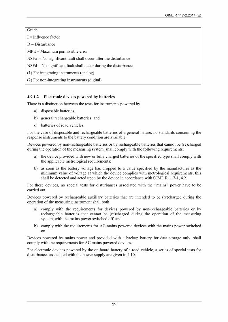
Table 4.9.9 Ripple on DC mains power Applicable standard IEC 61000-4-17 [27] and IEC 6100-4-1 Test method Introducing a ripple voltage on the DC input power port
Applicability
Only applicable for measuring instruments which are temporarily or permanently connected to a DC mains power network (distribution system) supplied by external rectifier systems while in operation and generally only applicable in an industrial environment. (see OIML D 11, 8.4.1). This test is only applicable to equipment powered by DC mains supply and is not applicable to equipment powered by a road vehicle battery.
Object of the test
Verification of compliance with the provisions in OIML R 117-1, 4.1.1 under conditions of the introduction of a ripple on the DC mains voltage. This test is not applicable for instruments connected to battery charger systems with incorporated switch mode converters.
Test procedure in brief
A test generator as defined in the referred standard shall be used. Before starting the tests, the performance of the generator shall be verified. The test comprises subjecting the EUT to ripple voltages such as those generated by traditional rectifier systems and/or auxiliary service battery chargers overlaying on DC power supply sources. The frequency of the ripple voltage is the applicable power frequency or a multiple (2, 3 or 6) dependant on the rectifier system used for the mains (as specified in the product specification). The waveform of the ripple, at the output of the test generator, has a sinusoid-linear character. The test shall be applied for at least 10 min or for the period of time necessary to allow a complete verification of the EUT’s operating performance.
During the tests, the EUT shall be in operation. Simulated inputs are permitted. Tests shall be performed at a minimum of one flowrate.
Percentage of the nominal DC voltage 2 %
Restrictions The test level is a peak-to-peak voltage expressed as a percentage of the nominal DC voltage, UDC.
Permitted maximum deviation
a) For interruptible measuring systems: either significant faults do not occur or checking facilities detect a malfunctioning and act upon it in accordance with OIML R 117-1, 4.3 when significant faults occur.
b) b) for non-interruptible measuring systems: no significant faults occur.
OIML R 117-2:2014 (E)
35
Table 4.9.10 Surges on AC and DC mains power lines
Applicable standard IEC 61000-4-5 [24]
Test method Introducing electrical surges on the mains power lines
Applicability Only applicable for electronic measuring instruments which are temporarily or permanently connected to a mains power network while in operation
Object of the test Verification of compliance with the provisions in OIML R 117-1, 4.1.1 during conditions where electrical surges are superimposed on the mains voltage.
Test procedure in brief
A surge generator as defined in the referred standard shall be used. The characteristics of the generator shall be verified before connecting the EUT.
The test comprises exposure of the EUT to electrical surges for which the rise time, pulse width, peak values of the output voltage/current on high/low impedance load and the minimum time interval between two successive pulses are defined in the referred standard.
At least 3 positive and 3 negative surges shall be applied.
On AC mains supply lines the surges shall be synchronized with the AC supply frequency and shall be repeated such that injection of surges on all the 4 phase shifts: 0°, 90°, 180° and 270° with the mains frequency is covered.
The injection network circuit depends on the applicable conductor and is defined in the referred standard.
The surges are applied during all the time necessary to perform the test; to that purpose more surges than indicated above may be necessary.
During the tests, the EUT shall be in operation. Simulated inputs are permitted. Tests shall be performed at a minimum of one flowrate.
Test level specifications: Parameter mode value Unit
Surge voltage peak
Line to line: 1.0 kV
Line to earth: 2.0 kV
Restrictions This test does not apply to devices powered by a road vehicle battery.
Permitted maximum deviation
a) For interruptible measuring systems: either significant faults do not occur or checking facilities detect a malfunctioning and act upon it in accordance with OIML R 117-1, 4.3 when significant faults occur.
b) For non-interruptible measuring systems: no significant faults occur.
In either a) or b) above, human intervention is permitted to put the EUT into operation after the test (e.g. replacing a fuse), provided that all relevant data is available after the human intervention.
OIML R 117-2:2014 (E)
36
Table 4.9.11 Radiated RF electromagnetic fields
Applicable standard IEC 61000-4-3 [22]; IEC 61000-4-20 [yy]
Test method Exposure to radiated radio frequency electromagnetic fields
Applicability Only applicable for electronic measuring instruments containing active electronic circuits
Object of the test Verification of compliance with the provisions in OIML R 117-1, 4.1.1 under conditions of exposure to electromagnetic fields.
Test procedure in brief
The EUT is exposed to electromagnetic fields with the required field strength and the field uniformity as defined in the referred standard.
The level of field strength specified refers to the field generated by the unmodulated carrier wave.
The EUT shall be exposed to the modulated wave field. The frequency sweep shall be made only pausing to adjust the RF signal level or to switch RF-generators, amplifiers and antennas if necessary. Where the frequency range is swept incrementally, the step size shall not exceed 1 % of the preceding frequency value.
The dwell time of the amplitude modulated carrier at each frequency shall not be less than the time necessary for the EUT to be exercised and to respond, but shall in no case be less than 0.5 s.
Adequate EM fields can be generated in facilities of different type and setup, the use of which is limited by the dimensions of the EUT and the frequency range of the facility.
The expected most critical frequencies (e.g. clock frequencies) shall be analyzed separately.
During the tests, the EUT shall be in operation. Simulated inputs are permitted. Tests shall be performed at a minimum of one flowrate.
Test levels Test levels may be specified according to OIML R 117-2, Tables 4.9.11.1 and 4.9.11.2.
OIML R 117-2:2014 (E)
37
Table 4.9.11.1 Electromagnetic fields of general origin
Test level index 2 3 Unit
Frequency range (26) 80–1000 MHz 3 10 V/m
Modulation 80 % AM, 1 kHz, sine wave
Permitted maximum deviation
a) For interruptible measuring systems: either significant faults do not occur or checking facilities detect a malfunctioning and act upon it in accordance with OIML R 117-1, 4.3 when significant faults occur.
b) For non-interruptible measuring systems: no significant faults occur.
Table 4.9.11.2 Electromagnetic fields specifically caused by wireless communication networks
Test level index
3 Unit
Frequency range 446 MHz(1) 10
V/m (0.8–3) GHz (2),(3) 10
Modulation 80 % AM, 1 kHz, sine wave
Notes
(1) Applicable only for the Europe region. (2) The main test level selection criteria should be the consequences
of failure of an instrument located at the expected minimum distance from a radiating source for wireless communication. (see 8.4.10 and Annex G of IEC 61000-4-3) and the possibility of fraud by using such a radiating source (such as a mobile phone or a transceiver). Selection of the level indexed 3 is suggested to apply only when the manufacturer of the measuring instrument specifies a minimum distance allowed between licensed communication transmitters and the measuring instrument. In all other cases the level indexed 4 is to be applied.
(3) It is not intended that tests need to be applied continuously over the entire frequency range of (1–6) GHz and may be reduced to cover just the specific frequency bands nationally allocated for RF emitting sources. (see IEC /TR 61000-2-5 [26]). Reduction of the test to cover the frequency range (1.4–3) GHz is expected to cover all wide beam and omni-directional emitting sources.
OIML R 117-2:2014 (E)
38
Table 4.9.11.3 Conducted (common mode) currents generated by RF EM fields
Applicable standard IEC 61000-4-6 [25]
Test method Injection of RF currents representing exposure to RF electromagnetic fields
Applicability Only applicable for electronic measuring instruments containing active electronic circuits and equipped with external electrical wiring (mains power, signal, data and control lines)
Object of the test Verification of compliance with the provisions in OIML R 117-1, 4.1.1 while exposed to electromagnetic fields.
Test procedure in brief
An RF EM current, simulating the influence of EM fields shall be coupled or injected into the power ports and I/O ports of the EUT using coupling/decoupling devices as defined in the referred standard.
The characteristics of the test equipment consisting of an RF generator, (de-)coupling devices, attenuators, etc. shall be verified before connecting the EUT.
During the tests, the EUT shall be in operation. Simulated inputs are permitted. Tests shall be performed at a minimum of one flowrate.
One of the following test levels may be specified:
Test level index 2 3 Unit
RF amplitude 3 10 V (e.m.f.)
Frequency range 0.15–80 MHz
Modulation 80 % AM, 1 kHz sine wave
Permitted maximum deviation
a) For interruptible measuring systems: either significant faults do not occur or checking facilities detect a malfunctioning and act upon it in accordance with OIML R 117-1, 4.3 when significant faults occur.
b) For non-interruptible measuring systems: no significant faults occur.
OIML R 117-2:2014 (E)
39
4.10 Tests for EUTs powered by a road vehicle battery
Table 4.10.1 Voltage variations
Applicable standard ISO 16750-2 [aa]
Test method Variation in supply voltage
Applicability Applicable to all measuring instruments supplied by the internal battery of a vehicle and charged by use of a combustion engine driven generator
Object of the test Verification of compliance with the provisions in OIML R 117-1, 4.1 under conditions of high voltage (for example while charging) and low battery voltage.
Test procedure in brief
The test comprises exposure to the specified maximum and minimum power supply voltage conditions for a period of time necessary for the EUT to be exercised and respond. The test durations shall be a minimum of one minute.
During the tests, the EUT shall be in operation. Simulated inputs are permitted. Tests shall be performed at a minimum of one flowrate.
One of the following test levels may be specified:
Nominal battery voltage Unom = 12 V Unom = 24 V Units
Test level index (1) (2) A B C D E F G H
Lower limit 6 8 9 10.5 10 16 22 18 V
Upper limit 16 16 16 16 32 32 32 32 V
Notes
(1) In ISO 16750-2 [41] test levels are called “Code”. (2) The recommended test level for these tests are:
Code C for 12 V batteries and Code F for 24 V batteries.
Permitted maximum deviation
At both the upper supply voltage level and the lower supply voltage level:
• all functions shall operate as designed.
• all errors shall be within the maximum permissible errors.
Test method Electrical transient conduction along supply lines
Applicability Applicable to all measuring instruments which while in operation are supplied by the internal battery of a vehicle which may at the same time be charged by use of a combustion engine driven generator
Object of the test
Verification of compliance with the provisions in OIML R 117-1, 4.1.1 under the following conditions:
• transients due to a sudden interruption of current in a device connected in parallel with the device under test due to the inductance of the wiring harness (pulse 2a);
• transients from DC motors acting as generators after the ignition is switched off (pulse 2b);
• transients on the supply lines which occur as a result of the switching processes (pulses 3a and 3b).
Test procedure in brief
The test comprises exposure of the EUT to disturbances on the power voltage by direct coupling into the supply lines.
During the tests, the EUT shall be in operation. Simulated inputs are permitted. Tests shall be performed at a minimum of one flowrate.
One of the following test levels may be specified (IV is recommended):
Test level index III IV Min. number
of pulses or test time
Test pulse Pulse voltage Us Pulse voltage Us
Unom = 12 V Unom = 24 V Unom = 12 V Unom = 24 V
2a +37 V +37 V +50 V +50 V 500 pulses
2b +10 V +20 V +10 V +20 V 10 pulses
3a –112 V –150 V –150 V –200 V 1 h
3b +75 V +150 V +100 V +200 V 1 h
Notes
Test pulse 2b is only applicable when the EUT is connected to the battery via the main switch of the vehicle. So, if the manufacturer of the EUT has not specified that the EUT is connected directly to the battery, test pulse 2b is not applicable. The recommended values for the level indexed IV, concern the maximum levels as defined in ISO 7637-2 (2004). Test pulses: minimum of 500 for 2a.
Permitted maximum deviation
a) For interruptible measuring systems: either significant faults do not occur or checking facilities detect a malfunctioning and act upon it in accordance with OIML R 117-1, 4.3 when significant faults occur.
b) For non-interruptible measuring systems: no significant faults occur.
OIML R 117-2:2014 (E)
41
Table 4.10.3 Battery voltage variations during starting up a vehicle engine
Applicable standard ISO 16750-2 [aa]
Test method Supply voltage variation due to energizing the starter motor of a vehicle
Applicability Measuring instruments powered by on-board DC battery and which may be in operation while the vehicle engine is started
Object of the test
Verification of compliance with the provisions in OIML R 117-1, 4.1.1 under conditions of starting the vehicle engine (during and after cranking).
Test procedure in brief
The test comprises exposure of the EUT to a typical supply voltage characteristic simulating the voltage variation while cranking the engine using a DC electrical starter motor.
During the tests, the EUT shall be in operation. Simulated inputs are permitted. Tests shall be performed at a minimum of one flowrate.
The following test levels may be specified:
Nominal battery voltage Unom = 12 V Unom = 24 V
Unit Test profile(1) I II III IV I II III
US 8 4.5 3 6 10 8 6 V
UA 9.5 6.5 5 6.5 20 15 10 V
t8 1 10 1 10 1 10 1 s
tf 40 100 100 100 40 100 40 ms
Notes 1) As specified in ISO 16750-2.
Permitted maximum deviation
a) For interruptible measuring systems: either significant faults do not occur or checking facilities detect a malfunctioning and act upon it in accordance with OIML R 117-1, 4.3 when significant faults occur.
b) For non-interruptible measuring systems: no significant faults occur.
OIML R 117-2:2014 (E)
42
Table 4.10.4 “Load dump” test
Applicable standard ISO 16750-2 [aa]
Test method Supply voltage variation due to disconnecting a discharged battery
Applicability Measuring instruments powered by on-board DC battery and which may be in operation while the vehicle engine is running
Object of the test Verification of compliance with the provisions in OIML R 117-1, 4.1.1 under conditions of disconnecting a discharged vehicle battery while the charging alternator is running.
Test procedure in brief
The test comprises exposure of the EUT to a typical pulse on the supply voltage, simulating the voltage peak due to the impedance of connected loads when disconnecting the battery.
During the tests, the EUT shall be in operation. Simulated inputs are permitted. Tests shall be performed at a minimum of one flowrate.
Nominal battery voltage Unom = 12 V Unom = 24 V Unit
Test pulse shape(1) I II I II
US 80 100 150 200 V
Ri 0.5 4 1 8 V
tr 10 10 10 10 ms
td 40–400 40–400 100–350 100–350 ms
Notes (1) As specified in ISO 16750-2.
Permitted maximum deviation
a) For interruptible measuring systems: either significant faults do not occur or checking facilities detect a malfunctioning and act upon it in accordance with OIML R 117-1, 4.3 when significant faults occur.
b) For non-interruptible measuring systems: no significant faults occur.
OIML R 117-2:2014 (E)
43
5 Testing procedures for meter sensors and measuring devices
5.1 General information The meter sensor/measuring device may be tested in either a test bench or in a measuring system. It shall be installed according to the manufacturer’s specification (meter position(s), straight pipes, flow straightening device, minimum back pressure, software setting/configuration, warm-up time, etc.). Low-flow cut-off (if applicable) is set at minimum value.
Note: See OIML R 117-1, 3.1.5.4 on turbine meters and other meter types concerning zero-offset.
Metrological stability shall be achieved before any testing is started. This means that the system shall operate within the repeatability error of OIML R 117-1, 3.1.2.2 (see Annex X, X.5.1 for advice on this).
Before conducting tests, it is necessary to evaluate the meter sensor/measuring device by using the general checklist given in OIML R 117-3 and the relevant points of the checklist given in Annex X, Table X.2.1 (cross reference table to type approval of specific components).
Note: Specific components allowed to receive type approval are only those for which partial MPEs and/or requirements for acceptance (pass/fail criteria) have been defined.
In accordance with the requirements of OIML R 117-1, 6, tests should be carried out at the limits of the rated operating conditions – the limits of pressure, temperature, density, and viscosity. It is possible to reduce the number of liquids to be tested if it can be shown, through technical analysis of the metering principals, that all requirements are fulfilled for any other liquid.
Definition of meter model: Different sizes of meter sensors/measuring transducers having family similarities in the principle of operation, construction and materials. A size is defined by the nominal size of the measuring element of the meter sensor, not the size of the pipe connection.
Meter selection – family of meters
When selecting which sizes of a family of meters are to be tested, the following rules shall be considered:
• the type evaluation authority shall declare the reasons for including and omitting particular meter sizes from testing;
• meters which have the most extreme operating parameters within a family shall be considered for testing (e.g. the largest flowrate range, the highest peripheral (tip) speed of moving parts, etc.);
• endurance tests shall be applied to meters where the highest wear is expected;
• all performance tests relating to influence quantities and disturbances shall be carried out on one size from a family of electronic meters.
One way of selecting sizes to test is to use Figure 5.1. Each line represents one family, meter 1 being the smallest. The family members underlined in Figure 5.1 are then selected for testing. The sizes not tested shall be within the range of 0.5 × Qmax ≤ Qmax ≤ 2 × Qmax of the adjacent sizes.
OIML R 117-2:2014 (E)
44
1
1 2
1 2 3
1 2 3 4
1 2 3 4 5 1 2 3 4 5 6
Figure 5.1 Families of meters pyramid
Depending on sensor size, the tests to be carried out are as follows (the selection of sizes to be tested shall be justified and explained in the test report):
Table 5.1
Subclause Type of test Selection of meter size to be tested 5.3.1 Indication at
zero flowrate Subclause 5.3.1 only applies for electro-magnetic, ultrasonic, and massflow meters. For those meter types, a selection of meter sizes according to Figure 5.1.
5.3.2 Accuracy at metering conditions
A selection of meter sizes according to Figure 5.1.
5.3.3 Accuracy at limits of working range
If documentary evidence is given that technological similarities exist between sizes, testing is conducted on a reduced number of sizes.
See also Annex X, X.5.3.3 for additional advice on this. 5.3.4 Flow
disturbances (optional)
Only for meters sensitive to flow profile.
This test is not applicable if the verification is performed at its final installation (stated in the type approval certificate).
If documentary evidence is given that technological similarities exist between sizes, testing is conducted on a reduced number of sizes.
5.3.5 Inclination test, etc.
Only for drum meters. All sizes.
OIML R 117-2:2014 (E)
45
Subclause Type of test Selection of meter size to be tested 5.4 Endurance test Only for meters with moving parts/parts under mechanical stress (this
means that Coriolis, ultrasonic, and electromagnetic meters are not required to be tested under 5.4).
Only for those sizes of a model for which the highest wear is expected.
Note 1: The “durability” requirement is met without this endurance test (for meters not actually tested under 5.4) because the meter will be running for more than 100 hours during all of the other tests.
Note 2: This is a significant change from the endurance requirements of OIML R 117-1. OIML R 117-1 will reflect this change in a future revision.
5.5 Minimum measured quantity
A selection of meter sizes according to Figure 5.1 (not applicable for pipeline meters).
5.6 Climate and disturbance tests
One size only in a family.
5.2 Test equipment To determine the amount of liquid passed through the meter sensor/measuring transducer, a standard test measure (OIML R 120), weighing machine (OIML R 76), pipe prover (OIML R 119) or master meter can be used. Standards, instruments and methods used shall suit the purpose, be traceable to international standards or to national standards traceable to international standards and be part of a reliable calibration program. Any test methods and test volume may be used provided that it is described in the test report and is accompanied by an uncertainty statement/reference to accreditation, demonstrating that the expanded uncertainty is in accordance with 4.2.
The volume of the supply tank shall be of sufficient capacity to not cause foaming of the liquid or a rise in temperature during the tests.
Note: It is preferable that all gas elimination devices should be vented back to the supply tank to avoid changing the test liquid specifications.
The temperature and pressure of the liquid passing through the meter sensor, measuring device or meter shall be measured close to the meter sensor/measuring device.
OIML R 117-2:2014 (E)
46
5.3 Accuracy
5.3.1 Indication at zero flowrate
The test for reading at zero flowrate should not exceed line C of OIML R 117-1, Table 2, at minimum flowrate (OIML R 117-1, 3.1.5.4).
Note: 5.3.1 only applies for electro-magnetic, ultrasonic, vortex, and massflow meters. For those meter types, apply selection of meter sizes according to Figure 5.1.
5.3.2 Accuracy at metering conditions
5.3.2.1 Accuracy at metering conditions (this subclause is not applicable to drum meters for alcohol; these meters are covered in 5.3.2.2)
Object of the test
The objective of this test is to verify that all individual measurement results at each flowrate meet the requirements concerning the maximum permissible errors.
General information
The flowrates of the measuring point are defined by
max1 QKQ Fn ×= −
where nF is a sequence number of the flowrate test, and
11
max
min−
=
FN
QQK
where NF is the number of flowrates as in the following table:
Qmax / Qmin ratio NF
<5 3
5 – 9 5
10 – 12 6
13 – 21 7
22 – 35 8
>35 9
Note 1: For turn-down ratios that are not a whole number, the ratio shall be rounded to the nearest whole number.
Note 2: When testing for an expanded flow range, new test points are added outside the old flow range, without the need to recalculate the old test points.
The above table shows that the set rate of flow through the measurement transducer shall not differ by more than 10 % from the calculated flowrate (except at Q(1) where 20 % is allowed). Furthermore, the limits for the measurement transducer specified by Qmax and Qmin shall not be exceeded.
Three independent and identical tests shall be carried out at each flowrate. The result (absolute value) of each of these three tests must not exceed line B of OIML R 117-1, Table 2.
The difference between the largest and the smallest results of the three successive measurements (range) is a measure of the repeatability error and shall, according to OIML R 117-1, 3.1.2.2, not be greater than 2/5 of Line A of OIML R 117-1, Table 2, for amounts greater than 5 times the minimum measured quantity.
If the measurement transducer is intended to be used together with a mechanical calculator/indicating device:
• tests shall be performed together with that mechanical calculator/indicating device;
• if that mechanical calculator/indicating device also has a price indicating device, the tests shall be performed at two unit prices which correspond to the maximum and minimum torques. This is generally near the maximum and minimum unit prices.
1. Fill in test report __________ (OIML R 117-3).
2. Draw an error-curve with Evi as a function of Q for each liquid and each unit price (optional).
5.3.2.2 Accuracy at metering conditions for drum meters for alcohol
For drum meters for alcohol, this test is performed without the sampling device, if applicable.
Meters are tested at the following flowrates, 3 tests at each flowrate:
Drum meter flow rate tests
Drum meter
Flowrate (dm3/min)
Q1 Q2 Q3
Small size (4 L per revolution) 0.5 to 1 1 to 2 2 to 3
Big size (20 L per revolution) 3 to 5 5 to 10 10 to 15
OIML R 117-2:2014 (E)
48
5.3.3 Accuracy at limits of working range
5.3.3.1 Accuracy at limits of temperature, pressure, viscosity and density
Perform accuracy tests according to 5.3.2 at limits of temperature, pressure, viscosity and density (when relevant, see OIML R 117-1, B.A.6.2), limited to 3 flowrates where, based on review of meter data at metering conditions per 5.3.2, the meter is determined to be least accurate. For electronic meters, these flowrates can be simulated if technically justified.
Note: The 3 suggested flowrates are:
Qmin;
((Qmax –Qmin) × 0.25) + Qmin; and
Qmax. State in the type approval certificate if the meter can be verified in one liquid and used in another (OIML R 117-1, 2.6.3).
5.3.3.2 Converted indication within a Coriolis meter
When a Coriolis meter uses its density measurement to calculate the liquid quantity in units of volume or if the density measurement is used by a flow computer as conversion, additional testing is required in addition to 5.3.2.1.
5.3.3.3 When a Coriolis meter uses its density measurement to calculate the liquid quantity in units of volume, next to an indication of mass, the error of the volume indication must also be determined. The accuracy of the converted volume indication is determined at the limits of density according to 5.3.2.1 with an MPE of line C of OIML R 117-1, Table 2, or half of the specified quantity deviation (Emin) in respect to the mass error. In this case, there are no additional requirements to the density.
Note: As an example, with an accuracy class of 0.3, the MPE on mass is 0.2 and the MPE on volume of a Coriolis meter is 0.1 in respect to the mass error.
5.3.3.4 When in addition to 5.3.3.2.1, the density measurement is used by a flow computer as a conversion, the density accuracy must also be determined in accordance with 5.3.3.1.
This test is only to be completed with all the manufacturer’s installation requirements followed as described in OIML R 117-1, 3.1.5.2. If appropriate, meters may be tested with at least one flow disturbance, at minimum and maximum flowrates. Three independent and identical tests shall be carried out at both flowrates. The Ev of each test must not exceed line A in OIML R 117-1, Table 2, without adjustment.
Alternative method 1 Use a “half-moon plate” in two orientations, 90° rotated, upstream of the meter. The plate blocks 0.125 × D of the diameter (see OIML R 49-2:2006 and ISO 4064-3:2005).
Alternative method 2 Use a ball valve upstream of the meter or the measurement transducer in several valve opening positions (90°, 80°, 65°, 45°).
Other flow disturbance test procedures may also be used, but justification and documentation must be provided. If necessary, additional disturbance configurations may be defined by the technology of the meter.
Note: See also Annex X.5.3.4.
OIML R 117-2:2014 (E)
49
5.3.5 Drum meters for alcohol
5.3.5.1 Conversion device (OIML R 117-1, 3.1.10.3)
The conversion device of a drum meter for alcohol is tested according to OIML R 117-2, 6 requirements according to OIML R 22, reference temperature 20 °C.
5.3.5.2 Volume of individual measuring chambers (OIML R 117-1 3.1.10.1)
The volume of an individual measuring chamber must not deviate more than ± 0.2 % from the mean volume.
5.3.5.3 Inclined drum axis (OIML R 117-1 3.1.10.1)
Drum meters for alcohol are tested with drum axis inclined 3º to the horizontal, at minimum flowrate. Three independent and identical tests shall be carried out at minimum flowrate. The change in result must not exceed half of line B in OIML R 117-1, Table 2.
5.3.5.4 Test of accuracy of the sampling device (OIML R 117-1, 3.1.10.4)
Error tests for all sampling ladles are made during one revolution of the drum. MPE of n volumes of ladles (where n is the number of chambers of the drum) is 10 % of the sum of the volumes of all ladles of the drum.
5.3.5.5 Test of volume of the containers (OIML R 117, 3.1.10.4)
The error of the volume compared to the nominal volume (stated in the type approval) shall not exceed
±5 % for the collecting containers (for samples),
–5 % for the volume of the inserting containers (for checking evaporation),
–2.5 % for the surge container (for liquid if the drum becomes stuck in the small size meter).
5.3.5.6 Test of accuracy of the thermometer (OIML R 117-1, 3.1.10.6)
The accuracy of the thermometer indication at the maximum temperature (to indicate too high an evaporation rate) shall not exceed ± 1 °C.
Note: Tests according to 5.3.5.4, 5.3.5.5 and 5.3.5.6 are not intended for volume measurement; they are intended for revenue.
5.4 Endurance test
Object of the test To determine the long-term stability of the meter sensor/measuring device. This test is only relevant for meters with moving parts.
General information An endurance test should be carried out at a flowrate between 0.8 × Qmax and Qmax of the measurement transducer using the liquid the measurement transducer is intended to measure or a liquid with similar characteristics.
The measurement transducer shall be of the same type and model as used for the accuracy test, but need not be the same individual device (see 5.3.2).
When the transducer is intended to measure different liquids, the test should be carried out with the liquid that provides the most severe conditions (normally the liquid of lowest viscosity).
OIML R 117-2:2014 (E)
50
An accuracy test shall precede the endurance test.
In principle the duration of the endurance test shall be 100 hours in one or several periods. Details of these test procedures shall be fully documented in the test report (including the choice of test liquid).
After the endurance test, the measurement transducer is subject to an accuracy test. The deviation between the mean value of the errors before and after the endurance test shall remain within line B of OIML R 117-1, Table 2 without any changes of the adjustment or corrections, as specified in OIML R 117-1, 3.1.2.3.
Test procedure 1. Perform accuracy tests in accordance with 5.3.2 at 3 flowrates (Qmin, 0.25–0.40 × Qmax, and
0.80 – 1.00 × Qmax).
2. Calculate Ēvi (B) for each flowrate.
3. Operate the transducer for 100 hours at a flowrate between 0.8 × Qmax and Qmax. For practical reasons, the volume may be divided up into a number of deliveries.
4. Perform an accuracy test in accordance with 5.3.2 at the same three flowrates. The unit price Pu shall be the same as during the initial accuracy test (only relevant for mechanical calculating/indicating devices).
5. Calculate Ēvi (A) and the difference Ēvi (A) – Ēvi (B) for each flowrate.
6. Fill in the test report _______ (R 117-3).
Note: If appropriate, the results from the accuracy tests according to 5.3.2 can be used for step 1 of the test procedure. In this situation the middle flowrate is the next lower flowrate from 5.3.2.
5.5 Accuracy on the minimum measured quantity
Object of the test To determine the error of volume indication Evi when the transducer delivers the minimum measured quantity.
Note: This testing requirement is not applicable for pipeline applications. For pipeline meters this test may be replaced by an evaluation/calculation of MMQ considering cyclic volume, resolution, time constant and flowrate.
General information The manufacturer or the applicant of an OIML certificate for a measurement transducer shall define the minimum measured quantity.
An accuracy test is carried out with a test volume equal to the minimum measured quantity at two flowrates, at Qmin and at the highest attainable flowrate, with standing start and stop (if applicable).
Three independent and identical tests shall be carried out at each flowrate.
The Ev must not exceed 2 times line B of OIML R 117-1, Table 2.
Note: The requirements on uncertainty given in 4.2 may not be fulfilled due to a “large” scale interval of indicator of the EUT.
OIML R 117-2:2014 (E)
51
If the measurement transducer is intended to be used together with a mechanical calculator/indicating device:
• tests shall be performed together with that mechanical calculator/indicating device;
• if that mechanical calculator/indicating device also has a price indicating device, the tests shall be performed at two unit prices which correspond to the minimum and maximum torques. This is generally near the minimum and maximum unit prices.
For electronic calculator/indicating devices the set unit price is not relevant.
For electronic measuring devices, additional tests shall be performed. These tests aim at verifying that the electronic devices comply with the provisions of OIML R 117-1, 4.1.1 with regard to influence quantities.
• Performance tests under the effect of influence factors:
When subjected to the effect of influence factors the equipment shall continue to operate correctly and the errors shall not exceed the applicable maximum permissible errors.
• Performance tests under the effect of disturbances:
For interruptible systems, when subjected to external disturbances the equipment shall either continue to operate correctly or detect and indicate the presence of any significant faults. For non-interruptible systems, no significant faults shall occur.
5.6.2 Test equipment
As described in 5.2.
5.6.3 Test procedures
As described in 4 with the following remarks:
The internal processes in an electronic meter under no-flow conditions are almost identical to those taking place under flowing condition; therefore, these tests need not be performed under flowing conditions. Tests under reference conditions should then also be performed under no-flow conditions.
For electromagnetic, Coriolis and ultrasonic flowmeters, it is usually necessary to fill the flowsensor with liquid (conductive liquid for electromagnetic flowmeters), for it to be in a proper condition to operate.
If the test is performed under no-flow condition, the low-flow cut-off and damping shall be set to zero, so changes can be observed.
Temperature measurement:
Electronic meters may be fitted with an internal temperature probe. When the temperature measurement is intended for internal corrections, the device is regarded to be an integral part of the meter, and is included in the testing.
OIML R 117-2:2014 (E)
52
Pressure measurement:
Pressure transmitters may be connected to an electronic meter for various purposes. If intended for correction, the pressure transmitter is considered as a part of the correction device and is included in the testing.
Test under reference conditions Before the series of tests, the EUT’s performance under reference conditions is verified.
For all types of electronic meters, the flowrate indicated under reference conditions is the basis for all further performance tests.
5.6.3.1 Test method, influence test type A
The object of an influence test is to verify that the electronic meter operates within its maximum permissible errors. Influence tests simulate the instrument’s rated operating conditions.
Ambient temperature tests are only relevant when liquid temperature does not “create” the meter temperature completely.
During this type of influence test, the meter’s flow indication is used to determine whether the meter still operates within the MPEs. However, maximum permissible errors apply to volume / mass and not flowrate. By calculating the effect of an observed change in flowrate on the device’s minimum flowrate, the maximum influence on a volume / mass measurement is calculated, which must be smaller than the MPE. Expressed mathematically:
(change in flowrate / minimum flowrate) × 100% < MPE
Note that the effect decreases with increasing flowrate.
5.6.3.2 Test method, influence test type B
The only difference between an influence test of type A and B is that during a test of type B, the instrument is switched off when the influence factor is applied to the instrument. The instrument’s performance is verified after the test. Typically these tests simulate conditions that the instrument is subjected to when it is not operating.
5.6.3.3 Test method, disturbance test
The object of a disturbance test is to verify that the instrument’s behavior does not change too much, due to the effects of disturbances. A disturbance test simulates conditions that are not considered to be a rated operating condition.
During the presence of the disturbances, the device’s flowrate indication must constantly be monitored for changes. The largest of these changes shall be no larger than the significant fault, when calculated as for influence tests.
OIML R 117-2:2014 (E)
53
6 Testing procedures for electronic calculators (that may be equipped with a conversion device), indicating devices, and associated devices
6.1 General information Tests are performed under reference conditions.
The software and configuration shall be checked according to the applicable requirements in 4 and the checklist in OIML R 117-3.
Reference tests required in 6 shall be conducted before each test and after the final test of the day.
Results of testing conducted in accordance with 6 shall be recorded in the applicable subclauses of OIML R 117-3.
6.1.1 Test setup
For electronic calculators and indication devices, the reference flow can be simulated (for instance by using a motor-driven pulser or electronic pulse simulator). In the case where the indicator is an integrated part of an electronic meter sensor, an electronic offset may be created to simulate a flow indication. Calculators often accept a range of input sensitivity. The calculator input sensitivity must be set to the maximum. Sufficient pulses shall be applied to meet an uncertainty of 1/5 of the MPE fault limit to be verified. It is advisable to apply at least 10 000 pulses to minimize the uncertainty caused by pulse-counting.
One of the following approaches shall be used:
First approach:
(When associated measuring devices are included in the evaluation)
Verification of the associated measuring instrument(s) requires that the liquid characteristics are directly applied to the inputs of the associated measuring device(s) (for example a temperature bath for the probe and/or pressure balance for the pressure sensor and/or reference liquid for a densitometer), to provide reference values for temperature, pressure, and density measurements.
Second approach:
Simulated signals representing temperature, pressure and/or density are applied to the EUT’s inputs. The true values for the simulated quantities are derived from the applied reference method (for example, temperature is derived from a resistor in the case of simulated temperature dependent resistances); pressure and or density may be derived from a generated current (in the case of a 4–20 mA pressure or density input(s)). Density may also be derived from a frequency, in the case of a frequency input.
6.1.2 Accuracy tests
Using an appropriate reference method, the values of the parameter characterizing the liquid are applied to the EUT.
OIML R 117-2:2014 (E)
54
6.1.3 Influence factor tests
For the description of the tests, see 4:
Dry heat: see 4.8.5
Cold: see 4.8.6
Vibration (random): see 4.8.8
AC mains voltage variation: see 4.9.2.1
DC mains voltage variation: see 4.9.2.2
Voltage variations (road vehicle battery) see 4.10.1
During the climate tests, the equipment used for simulating the deliveries and associated measuring instruments is kept outside the climatic chamber.
For each test the severity levels shall be determined as shown in 4.
6.1.4 Disturbance tests
For the severity levels, see 4.9.1.1.
For the description of the tests, see the following subclauses:
4.8.7: Damp heat, cyclic
4.9.3: AC mains voltage dips, short interruptions and reductions
4.9.4: Bursts (transients) on AC and DC mains
4.9.5: Electrostatic discharge (ESD)
4.9.6: Bursts (transients) on signal, data and control lines
4.9.7: Surges on signal, data and control lines
4.9.8: DC mains voltage dips, short interruptions and (short term) variations
4.9.9: Ripple on DC mains power
4.9.10: Surges on AC and DC mains power lines
4.9.11.1: Radiated, radio frequency electromagnetic fields - of general origin
4.9.11.2: Radiated, radio frequency electromagnetic fields specifically caused by wireless communication networks
4.9.11.3: Conducted (common mode) currents generated by radio frequency electromagnetic fields
4.10.2: Electrical transient conduction along supply lines (road vehicle battery)
In the case of the electromagnetic fields immunity tests, the equipment used for the simulation of the deliveries and associated measuring instruments is kept outside the generated electromagnetic field to prevent the simulation equipment from being disturbed by the RF field.
OIML R 117-2:2014 (E)
55
6.2 Electronic calculators and indicating devices
6.2.1 Accuracy tests (see tables in OIML R 117-3)
Using an appropriate reference method, three simulated flowrates (frequencies) are applied to the EUT: the minimum, medium and maximum value.
Based on the values applied by means of the reference methods and the volume (or mass, if that is the primary measurement signal) indicated by the calculator / indicating device the indicated value is compared with the reference value.
The value of the maximum permissible error for this device is specified in OIML R 117-1, 2.8.
6.2.2 Influence factor tests
Dry heat test and cold tests
Before, during, and after the dry heat test and cold test, a delivery shall be simulated.
During the dry heat and cold test, the indicated quantity value is compared with the reference value.
Vibration test
Before and after the vibration test, a simulated delivery is generated.
The indicated quantity value after the vibration test is compared with the reference value.
During the vibration test, the power is switched off.
The value of the maximum permissible error for this device is specified in OIML R 117-1, 2.8.
6.2.3 Disturbance tests
Before each test, reference deliveries are generated to determine the intrinsic error.
Damp heat cyclic test
Before and after the damp heat cyclic test, a simulated delivery is generated.
The indicated quantity value after the damp heat cyclic test is compared with the reference value.
During the damp heat cyclic test, the power is switched off.
During the disturbance a simulated delivery is made and the indication of the indication device is compared with the reference values.
Maximum allowable variation (see OIML R 117-1, 2.8).
• For interruptible systems: checking facilities shall detect a malfunction and act upon it in accordance with OIML R 117-1, 4.3.
• For non-interruptible systems: no significant faults shall occur.
OIML R 117-2:2014 (E)
56
6.3 Conversion device (as part of an electronic calculator)
6.3.1 First approach
6.3.1.1 Accuracy tests
If regarded as an electronic conversion device (ECD), the applied associated measuring devices are considered to be an integral part of the conversion device. Consequently, a conformity assessment is only valid for the EUT if applied in combination with the associated measuring device submitted with it for conformity assessment.
During the tests, the specific test conditions need to be applied to the ECD including its associated measuring devices, using the reference method.
The indicated converted quantity value is compared with the reference converted value (using an internationally accepted method).
For each of the applicable characteristics of the liquid (i.e. temperature, pressure, density, relative density, etc.) the minimum, medium, and maximum values are applied. Based on the values represented by the simulated signals, the indications of the converted quantities are verified.
Input values used for the verification of the conversion calculation (either the measured unconverted volume or the unconverted volume derived from a simulated input) are assumed to be without error.
The value of the maximum permissible error for this device is specified in OIML R 117-1, 2.7.1.2.
Note: The MPE requirement shall not be less than half of the minimum specified quantity deviation.
6.3.1.2 Influence factor tests
If the transducers and the sensor of the associated measuring devices are separated, only the transducers together with the flowcomputer are placed in the climate room.
For each of the applicable characteristics of the liquid (i.e. temperature, pressure, density, relative density, etc.) the medium value is applied and evaluated.
Dry heat test and cold tests
A delivery is simulated before, during, and after the dry heat test and cold test.
During the dry heat and cold test, the indicated converted quantity value is compared with the reference converted value (using an internationally accepted method).
Vibration test
A delivery is simulated before and after the vibration test.
The indicated converted quantity value after the vibration test is compared with the reference converted value (using an international accepted method).
During the vibration test, the power is switched off.
The value of the maximum permissible error for this device is specified in OIML R 117-1, 2.7.1.2.
Note: The MPE requirement shall not be less than half of the minimum specified quantity deviation.
6.3.1.3 Disturbance tests
Before and during the tests, a simulated delivery is generated.
For each of the applicable characteristics of the liquid (i.e. temperature, pressure, density, relative density, etc.) the medium value is applied and evaluated.
OIML R 117-2:2014 (E)
57
During the tests, the indicated converted value is compared with the reference converted value (using an internationally accepted method).
Before and after each test, a reference non-converted value is generated to determine the intrinsic error.
All of the different components are subject to the tests.
Damp heat cyclic test
A delivery is simulated before and after the damp heat cyclic test.
The indicated converted quantity value after the damp heat cyclic test is compared with the reference converted value (using an internationally accepted method).
During the damp heat cyclic test, the power is switched off.
Maximum allowable variation
• For interruptible systems: The value of the maximum permissible error for this device is specified in OIML R 117-1, 2.7.1.3.
• For non-interruptible systems: no significant errors shall occur.
6.3.2 Second approach
6.3.2.1 Accuracy tests of the calculator/conversion device
Following this second approach for the testing of a conversion device, it is possible to verify separately the accuracy of the associated measuring devices and to verify that the provisions for the calculator / indication device with conversion device are fulfilled.
The values represented by the simulated signals shall be compared with the values indicated by the flowcomputer.
In the case of conversion devices with configurable input sensitivity (measured unit per input signal unit), the input sensitivity must be set to the maximum.
For each of these quantities the minimum, medium, and maximum values are applied. Based on the values represented by the simulated signals, the indications of the quantities are verified (see OIML R 117-1, Table 4.1).
Based on internationally accepted standards and the values represented by the simulated signals, the correctness of the conversion calculation(s) is verified (see OIML R 117-1, 2.7.2.1.3).
For the verification of the calculations, tests shall be performed at three values distributed over the range of the equation. For equations split into sections, three tests in each section shall be performed.
For the verification of the conversion calculation, the measured volume or the volume derived from a simulated input is assumed to be without error.
If the signals to simulate the associated measuring devices are digital, the MPE and significant fault limit of the indications are restricted to rounding errors (see OIML R 117-1, 2.7.2.1.1).
6.3.2.2 Influence factor tests of the conversion/calculator device
For each of the applicable characteristics of the liquid (i.e. temperature, pressure, density, relative density, etc.), the medium value is applied and evaluated.
Dry heat test and cold tests
Before and after the dry heat test and cold tests, a simulated delivery is generated.
During the dry heat and cold test, the indicated converted quantity value is compared with the reference converted value (using an internationally accepted method).
OIML R 117-2:2014 (E)
58
Vibration test
Before and after the vibration test, a simulated delivery is generated.
The indicated converted quantity value after the vibration test is compared with the reference converted value (using an internationally accepted method).
During the vibration test, the power is switched off.
Maximum permissible error (see OIML R 117-1, 2.7.2.1, Table 4.1):
If the signals to simulate the associated measuring devices are digital, the MPE and significant fault limit of the indications are restricted to rounding errors (see OIML R 117-1, 2.7.2.1.1).
6.3.2.3 Disturbance tests of the conversion/calculating device
Before each test, a simulated reference delivery is generated to determine the intrinsic error.
For each of the applicable characteristics of the liquid (i.e. temperature, pressure, density, relative density, etc.), the medium value is applied and evaluated.
The equipment used to simulate the signals shall not be influenced by the tests.
The quantities and the conversion calculation are verified using the values represented by the simulated signals and internationally accepted standards.
Damp heat cyclic test
Before and after the damp heat cyclic test, a simulated delivery is generated.
The indicated converted quantity value after the damp heat cyclic test is compared with the reference converted value (using an internationally accepted method).
During the damp heat cyclic test, the power is switched off.
Maximum allowable variations (see OIML R 117-1, 2.7.2.1, Table 4.1):
If the signals to simulate the associated measuring devices are digital, the MPE and the significant fault limit of the indications are restricted to rounded errors (see OIML R 117-1, 2.7.2.1.1).
• For interruptible systems: either no significant fault shall occur or the checking facilities shall detect a malfunction and act upon it accordance with OIML R 117-1, 4.3.
• For non-interruptible systems: no significant faults shall occur.
6.4 Associated measuring devices
6.4.1 Accuracy tests of associated measuring devices
The associated measuring device is subjected to a known temperature, pressure or density or (when applicable) a combination of these at the limits of operation. During the tests, the specific test conditions shall be applied to the associated measuring devices using a reference method (for example: a temperature bath and/or pressure balance and/or reference liquid (true values)). Traceable and documented laboratory reference equipment shall be used. The values indicated by the calculator/indicating device for each of the characteristic quantities shall be used to determine the error for each of the associated measuring devices.
In the case of conversion devices with configurable input sensitivity (measured unit per input signal unit), the input sensitivity must be set to the maximum.
Three values of each of the parameters characterizing the liquid are applied to the EUT: the minimum, medium, and maximum values.
OIML R 117-2:2014 (E)
59
Based on the values applied by means of the reference method(s), the correctness of the values for temperature, pressure and/or density indicated on the electronic conversion device or other indicating device is verified.
Maximum allowable variations (see OIML R 117-1, 2.7.2.1, Table 4.1 and 2.7.2.2.3, Tables 4.2 and 4.3).
6.4.2 Influence factor tests on associated measuring devices
Dry heat test and cold tests
Before, during, and after the dry heat test and cold tests, the indicated measured value is compared with the reference value.
Vibration test
Before and after the vibration test, the indicated measured value is compared with the reference value.
During the vibration test, the power is switched off.
For each of the applicable characteristics of the liquid (i.e. temperature, pressure, density, relative density, etc.) the medium value is applied and evaluated.
Maximum permissible error (see OIML R 117-1, Tables 4.1, 4.2, and 4.3)
6.4.3 Disturbance tests on associated measuring devices
Before each test, the indicated value is compared with the reference value to determine the intrinsic error.
The reference equipment shall not be influenced by the tests.
The correctness of the quantity indications is verified by comparing them with the reference values. For each of the applicable characteristics of the liquid (i.e. temperature, pressure, density, relative density, etc.), the medium value is applied and evaluated.
Damp heat cyclic test
Before and after the damp heat cyclic test, the indicated measured value is compared with the reference value.
During the damp heat cyclic test, the power is switched off.
Maximum permissible error (see OIML R 117-1, Tables 4.1, 4.2, and 4.3)
6.5 Temperature conversion: Tests on the response time of the measuring system temperature sensor
See OIML R 117-1, 3.7.7 and 6.1.10 for further discussions on these requirements.
The desired temperature change is applied to the EUT using a suitable reference method. The output from the sensor shall be able to respond to 90 % of a temperature step change within 15 seconds or (if larger) within a time corresponding to the time needed to deliver, at Qmax, a quantity of twice the MMQ.
In the case of fuel dispensers, this would result in maximum time constants (τ) as found in the following table:
OIML R 117-2:2014 (E)
60
Table for subclause 6.5
Qmax [L/min]
40 80 130 200
MMQ [L]
5 10 20 50
Time [s]
15.00 15.00 18.46 30.00
Maximum τ [s]
6.51 6.51 8.02 13.03
OIML R 117-2:2014 (E)
61
7 Testing procedures for gas elimination devices
7.1 General information Clause 7 covers testing procedures for all three kinds of gas elimination devices mentioned in OIML R 117-1, 2.10: gas separators, gas extractors, special gas extractors.
The gas elimination device may either be type evaluated as a unit separate from the measuring system (MS) for which it is intended (see 7.2.1), or tested as a unit forming part of MS during type evaluation of the MS (see 7.2.2).
Note 1: In practice, the MS subject to type evaluation or verification is not tested in order to check the performance on gas elimination. In fact, the performance of the gas elimination device is established a priori on a specimen of the gas elimination device as a unit separate from the MS for which it is intended. The decision to fit a MS with a given kind of gas elimination device is based on an examination considering the worst conditions in which the MS could operate.
Note 2: For the purpose of clause 7, the term “gas” is used as a general term for “air/gas” or for “mixtures of air and gas”.
Note 3: For testing a gas elimination device, usually air is used as the gas introduced into the liquid, but any other appropriate gas (e.g. nitrogen) may be used as well.
If the gas elimination device is a separate unit (see 7.2.1), it is examined whether a type of a gas elimination device complies with the requirements in OIML R 117-1, 2.10.
A specimen of that type must be installed on a suitable test bench. The test bench comprises, among others, a pump upstream of the gas elimination device under test, a liquid meter and a standard, both located downstream of the gas elimination device.
The standard of the test bench serves the purpose to determine the volume Vn (without gas) of the delivered liquid without gas, so a suitable standard (e.g. a standard capacity tank) must be used from which gas entrapped in the liquid can escape freely.
The liquid meter of the test bench serves to determine the volume of both the delivered liquid and the gas left over in the liquid downstream of the gas elimination device, so the liquid meter is a measure for the efficiency of the gas elimination device, with its meter errors Evi (with gas).
Note: Concerning the type of the liquid meter, positive displacement meters are preferred because of their ability to measure the actual volume of liquid and of gas.
Prior to or after the determination of the meter errors Evi (with gas), the liquid meter shall be tested without gas in order to determine its meter errors Evi (without gas). The difference of the meter errors Evi (with gas) – Evi (without gas) represents the effect due to the influence of gas on the measurement result. For the purpose of clause 7 these values are denoted as the effect of the gas elimination device which shall not exceed the values of OIML R 117-1, 2.10.1.
Note: These values of OIML R 117-1, 2.10.1 do not depend on the accuracy class of the measuring system, but on the type of the liquid.
The type approval certificate of the gas elimination device shall clearly define the kind of gas elimination device which has been tested; in the case of gas separators, information shall be given whether the gas separator has been approved also as a gas extractor.
Note: According to OIML R 117-1, 2.10.2, a gas separator shall also be approved as a gas extractor if gaseous formations such as gas/air pockets liable to have a specific effect greater than 1 % of the minimum measured quantity can occur as well. So, if such tests have been carried out on the gas separator, the relevant information shall be given in the type approval certificate.
OIML R 117-2:2014 (E)
62
If the gas elimination device is a unit forming part of a MS (see 7.2.2), it shall be examined to determine whether the type of the gas elimination device complies with the requirements in OIML R 117-1, 2.10.
A specimen of that type of gas elimination device must be installed in the MS for which it is intended.
For the standard, the same applies as in the paragraph above.
For the liquid meter, the same applies as in the paragraph above, but the liquid meter is part of the MS. When the liquid meter of the MS is not capable of measuring the actual volume of gas (e.g. meters of the Coriolis type), during the gas elimination device test this liquid meter must be substituted by an appropriate type.
7.2 Testing
7.2.1 Test of a gas elimination device as a separate unit
Tests on gas elimination devices should be carried out for flowrates up to a maximum of 100 m³/h. For higher flowrates, characteristics may be determined by analogy with equipment of the same design and smaller dimensions.
Note: From long term experience it can be assumed that in general, gas elimination devices for flowrates ≤ 100 m³/h comply when their effective volume (volume between inlet and outlet) is, as a guide value, ≥ 8 % (maybe even less) of the quantity passing through the gas elimination device at Qmax during 1 min.
The test for flowrates > 100 m³/h is (for reasons of a lack of appropriate testing facilities for such high flowrates) not feasible and therefore it is desirable for the characteristics of meters for large flowrates to be determined by analogy to smaller sizes: for gas elimination devices for flowrates > 100 m³/h the guide value that they comply with is about twice the above mentioned value of 8 %. Nevertheless, for the acceptance of the determination by analogy, the manufacturer of the gas elimination device should underpin the assumption of conformity by valuable calculations. The acceptance of these calculations should be up to the authority in charge of type approval.
Note that for the determination by analogy, parameters such as the Reynolds number and the Froude number are not acceptable to underpin the assumption of conformity because these parameters are valid only for one-phase-fluids but which are not present when testing gas elimination devices.
The test liquid should either have the viscosity for which the device is intended or a greater viscosity. If the gas elimination device meets the 0.5 % criterion in OIML R 117-1, 2.10.1 with a test liquid of a viscosity greater than 1 mPa∙s (at 20 °C), no additional tests with a test liquid of a viscosity ≤ 1 mPa∙s are required.
As a general rule, the test volume of a test run shall be at least the volume of liquid without gas, delivered during one minute at Qmax of the gas elimination device.
The gas is either introduced by injection downstream of the pump, or by suction upstream of the pump.
• In the case of injection (which makes it possible to operate without changing the performance of the pump due to the entry of gas) the liquid and gas flows are adjusted by means of control valves.
OIML R 117-2:2014 (E)
63
• In the case of suction (which yields a pressure reduction by suction and by this reproduces the conditions in reality) the pump (before gas is added) must be set to Qmax of the gas elimination device (if the pump flow capacity is higher than needed it has to be adjusted accordingly). The pump should preferably be of the displacement type but it may also be of the centrifugal type if the supply tank feeds the pump by gravity. The gas flow must then be regulated by a valve positioned upstream of the pump.
The gas inlet is fitted with a shut-off/control valve and a non-return valve to prevent liquid from entering the gas inlet and draining out of the test bench.
A sight glass is installed in the liquid pipework downstream of the gas inlet and upstream of the gas elimination device in order that the added gas can be observed in the liquid. The added gas has to be clearly visible in the sight glass.
Note: When testing gas elimination devices, gas and liquid should normally be present as separate phases. This two-phase-state must be observable (by the sight glass).
If, during the test, the liquid pressure is relatively high (above 2 bar), the gas could become dissolved in the liquid and this would make the function of removing gas from the liquid in a two-phase-state impossible to test. On the other hand, in order to achieve the required Qmax, it might become necessary to increase the liquid pressure P to a relatively high value (e.g. above 2 bar), with the consequence that the gas becomes dissolved (the need for such a (relatively high) pressure may either lie in the characteristic of the test bench or of the gas elimination device or of both).
Even though this testing condition does not correspond to the desired two-phase-state, if the gas elimination device complies at the (relatively high) pressure P and this pressure is defined as the minimum admissible pressure of the gas elimination device, the gas elimination device will also comply when used at any other pressure ≥ minimum admissible pressure.
The volume of gas continuously entering the liquid is measured by a gas meter and isothermally converted to atmospheric pressure on the basis of the indication of a manometer fitted upstream of the gas meter.
The liquid pressure must be measured directly downstream of the gas elimination device (upstream of the liquid meter) to determine the lowest pressure at which the gas elimination device still meets the values in OIML R 117-1, 2.10.1.
A sight glass, downstream of the gas elimination device, is used to check that the gas is no longer visible in the liquid.
Note: A slanting in the pipework downstream of the liquid meter should be avoided to ensure that gas bubbles can escape in the normal way – thus keeping this pipework filled to the same level at the start and at the end of the test.
In the case where the gas elimination device is provided with an automatic stop-valve, the tests shall be carried out with this valve installed in the test bench.
Note: The test report for the gas elimination device has either to indicate the type of this valve or its characteristics concerning the shut off-speed. In the case of pneumatic driven valves, the test report should also indicate the length of the pneumatic control line between the gas elimination device and its automatic stop-valve. Consequently, the measuring system may either use the indicated type or a type of the same characteristics, and the length of the pneumatic control line shall be ≤ the length indicated by the test report.
OIML R 117-2:2014 (E)
64
7.2.1.1 Gas separator test
According to OIML R 117-1, 2.10.8, a gas separator designed for Qmax ≤ 20 m3/h shall ensure the elimination of any proportion by volume of gases relative to the measured liquid. The maximum proportion is 30 % gas for gas separators with a Qmax > 20 m³/h . The volume of gas Va is measured at atmospheric pressure in determining its percentage.
The gas separator must separate the added gas up to the values in OIML R 117-1, 2.10.1, and must stay fully functional.
An example of a test bench which continuously adds gas to the liquid is shown in Annex X.7.2.1.1, Figure 1.
Note: According to OIML R 117-1, 2.10.2, a gas separator shall also be approved as a gas extractor in the case where gaseous formations such as gas pockets liable to have a specific effect greater than 1 % of the minimum measured quantity can occur in the measuring system as well. So, if this is the case, the same tests as on gas extractors have to also be performed on gas separators.
Test procedure
All test runs must start and finish with the gas inlet closed and with the delivery pipe of the test bench full and pressurized.
First determine the (relative) errors Evi (without gas) of the liquid meter at least from Qmax to Qmin of the gas separator without adding gas, at the minimum pressure achievable on the test bench (e.g. pressure < 2 bar) (leading to the error curve of the liquid meter under no gas conditions).
Determine the list of flowrates according to 5.3.2.1.
Then, determine the (relative) errors Evi (with gas) of the liquid meter by continuously adding gas to the liquid, in increasing amounts of the gas/liquid ratio up to the maximum proportion (leading to the error curve of the liquid meter under gas conditions). This procedure shall be terminated under the condition of either a) or b):
a) when it covers the entire range of gas/liquid ratio Va/Vn; b) when discharge stops automatically.
• For each test run at a given gas/liquid ratio start the test run at Qmax of the gas separator, at the minimum pressure achievable on the test bench, with the gas inlet closed. When Qmax is reached, introduce gas of the required proportion by regulating the flowrate of the gas by using the air inlet throttle valve.
Note: The flowrates of the liquid meter obtained under gas conditions need not necessarily be the same as under no gas conditions.
Note the gas bubbles in the sight glass of the test bench upstream of the gas separator.
Check the liquid and gas flowrate together with the pressure values.
• Stop the flow of gas and liquid when the test volume of the liquid is reached; in the case where there is no flow for more than 10 seconds before the test volume of the liquid is reached, close the gas inlet and terminate the test run until the test volume of the liquid is reached.
• Read the liquid volume Vs of the liquid standard and the volume Vi indicated by the liquid meter and calculate Vn. Measurement results gained below Qmin shall be disregarded.
OIML R 117-2:2014 (E)
65
• Convert the (corrected) volume indication Vmetered gas of the gas meter at the pressure pt to the amount of added gas Va at the atmospheric pressure patmospheric by:
catmospheri
catmospheritgas metereda
)(p
ppVV
+⋅=
In the case of sucked-in gas, assume pt = 0.
• Calculate the ratio of Va / Vn and the (relative) meter error Evi (with gas) = (Vi – Vn)/Vn and determine the difference between Evi (with gas) and Evi (without gas) as the effect of the gas separator due to the added gas.
Note: As the flowrates of the liquid meter obtained under gas conditions need not necessarily be the same as under no gas conditions, calculate the difference between the error curve under no gas conditions and the error curve under gas conditions.
7.2.1.2 Gas extractor test
The test bench has a gas reservoir for creating a gas pocket. Care shall be taken that upstream of the gas extractor the liquid and gas are still present as separate phases and that the injected gas does not become dissolved in the liquid (thus conflicting with the test conditions of OIML R 117-1, 2.10.9, first paragraph requiring a gas pocket).
The other parts of the liquid pipework upstream of the meter must be kept full. The gas pocket is then added to the liquid at Qmax of the gas extractor.
The volume of the gas pocket under atmospheric pressure is ≥ the minimum measured quantity of the gas extractor.
Note 1: The MMQ of the gas extractor is defined by the applicant, but as a general rule the minimum measured quantity (MMQ) of the gas extractor should be set to a volume corresponding to the flow at Qmin during 1 minute (if only Qmax is known, then Qmin can be derived from the permissible ratio between the maximum and the minimum flowrates of the measuring system according to OIML R 117-1, 2.3.3.3).
Note 2: OIML R 117-1, 2.10.9, first paragraph requires that the created gas pocket must not be smaller than the MMQ, but does not require that the gas pocket is greater than the MMQ.
Note 3: The volume of the gas pocket defines the necessary volume of the gas reservoir. In the case where the necessary volume at atmospheric pressure patmospheric is not provided, the gas pocket may also be created at a pressure pt, with patmospheric ≤ pt ≤ pmin of the gas extractor (by then converting the volume of the gas pocket at pt to the volume of the gas pocket at patmospheric).
Note 4: An example of a test bench which adds gas pockets to the liquid is shown in Annex X.7.2.1.2, Figure 2.
7.2.1.2.1 Gas pocket test
Make an initial test run without a gas pocket, at Qmax of the gas extractor and at the minimum pressure.
Note: In order to avoid the gas becoming dissolved in the liquid, the pressure should be < 2 bar.
Then make three test runs by adding the gas pocket of the required volume to the liquid.
OIML R 117-2:2014 (E)
66
Test steps
1) Vent the liquid pipework completely from entrapped gas and create the gas pocket.
2) Perform the test run at Qmax and the lowest liquid pressure. When Qmax is reached, open the gas reservoir / the injection valve to discharge the gas pocket into the liquid stream.
3) After the gas extractor had acted upon the gas pocket, the flowrate will resume Qmax; continue the delivery at Qmax and stop it when the test volume of the liquid is reached.
4) Read the standard volume Vs and the volume Vi indicated by the meter and calculate Vn from Vs.
5) Calculate the meter error Evi (with gas) = (Vi – Vn) and determine the difference between the meter error Evi (with gas) and Evi (without gas) as the absolute error of the gas elimination device due to the added gas.
Note: Gas is not added continuously but only once during the test run, so that Evi (with gas) will occur only once and independently from the delivered liquid volume. Therefore, for the determination of the difference between the meter error Evi (with gas) and Evi (without gas), the absolute (and not the relative) error has to be considered. The difference then must be ≤ 1 % of the volume of the added gas pocket.
7.2.1.3 Special gas extractor test
Note: Special gas extractors are mainly (but not exclusively) used for measuring systems on road tankers when compartments are completely emptied (operation of the special gas extractor as a gas extractor), but gas can also occur which is continuously and slightly mixed with the liquid (operation of the special gas extractor as a gas separator under the conditions of OIML R 117-1, 2.10.9 second paragraph).
For the gas extractor function of special gas extractors not intended for road tankers, the analog tests as on gas extractors described in 7.2.1.2 must be carried out.
For the gas extractor function of special gas extractors intended for road tankers, see 7.2.1.4.
In order to determine the effect of the gas elimination device arising from gaseous formations such as pockets, the supply tank is filled with the test volume. The liquid is then emptied through the meter into the standard without operating the start/stop valve of the test bench. For deliveries not by pump but by gravity, a pipework of the test bench is used which bypasses the pump.
In the case where there is an automatic shut-off valve installed in the liquid pipework of the test bench and operated by the special gas extractor, the gas pocket may be created by emptying the pipework between the supply tank and the gas extractor.
Note: In the case where the test bench has more than one supply tank, a more common way to carry out the gas pocket test is to switch during the delivery to an empty supply tank. The switching test covers the gas pocket test.
For the gas separator function of special gas extractors, the test with continuous gas supply as on gas separators in 7.2.1.1 must be carried out at Qmax of the special gas extractor, but with the gas proportion as defined in OIML R 117-1, 2.10.9 second paragraph.
Note: The maximum achievable flowrate for MS on road tankers with gravity discharge is normally below Qmax of the special gas extractor. To reach Qmax of the special gas extractor (in order to meet the requirement of OIML R 117-1 for testing at Qmax) the gravity discharge must be supported by simulating an increased static height. This can be accomplished by pressurizing the supply tank. An increase of around 0.4 bar (which could vary due to the test bench used) results in a simulated increase of the static height by 4 m). A pressure regulator shall guarantee a stable gas pressure in the supply tank during the tests.
OIML R 117-2:2014 (E)
67
The gas is either injected into the supply pipework or sucked in upstream of the pump, by creating an entry of gas over a gas meter and partly closing the valve of the supply tank.
An example of a test bench which adds to the liquid gas pockets and gas continuously is shown in Advice Annex X.7.2.1.3, Figure 3. This test bench is similar to Figures 1 and 2, but reproduces the actual conditions of deliveries from road tankers to underground tanks, e.g. at petrol stations: the supply tank is located above the special gas extractor and above the meter (i.e. at a level corresponding to that of the road tanker) and the standard is located approximately 4 m below the meter.
7.2.1.4 Gas extractor function tests of the special gas extractors intended for road tankers (viscosity ≤ 20 mPa·s)
The following tests must be carried out:
• residual discharge test from the supply tank;
• gas pocket test;
• switching test to an empty supply tank.
The switching test to an empty supply tank also covers the gas pocket test.
Note: The above tests cover all cases where gas pockets on road tankers occur (or might occur) during a delivery:
• the residual discharge test from the supply tank covers the (usual) case where the compartment of a road tanker is completely emptied at the end of a delivery;
• the gas pocket test covers the case where at the start of the delivery gas pockets may occur, e.g. when the pipe between the bottom valve and the special gas extractor is empty, when the measuring system is fed by a compartment on a trailer;
• the switching test to an empty supply tank (which is the most severe test method for the gas extractor function) covers the cases:
o where at the start of the delivery gas pockets may occur, e.g. when the pipe between the bottom valve and the special gas extractor is empty, when the measuring system is fed by a compartment on a trailer;
o where gas pockets occur at measuring systems without automatic interlock of bottom valves and where one switches during the delivery to an empty compartment.
All tests are carried out according to the specification of the special gas extractor with gravity and pumped discharge.
7.2.1.4.1 Residual discharge test from the supply tank
This test consists of completely emptying a supply tank over the special gas extractor.
Before any test runs are carried out the test bench, including the line from the supply tank, must be vented of any entrapped gas.
One initial test run shall be carried out by delivering the liquid quantity until the pipe is empty and the delivery stops. Then make three residual discharge test runs.
A test run is carried out with a test volume corresponding to Qmax of the special gas extractor during 1 minute. The pipe route is enabled depending on the type of test (gravity discharge or pump operation). During the delivery from the supply tank over the special gas extractor, the supply tank shall run completely empty.
Note: The same consideration of Evi (with gas) as in 7.2.1.2 applies.
OIML R 117-2:2014 (E)
68
When the special gas extractor is provided with its own automatic stop-valve (which shall then be installed in the test bench together with the special gas extractor), the test run is finished when the supply tank has run completely empty and the special gas extractor no longer opens its automatic stop-valve.
Note: When the standard is a proving tank and the volume of the delivered liquid is below the nominal capacity of the proving tank, it is necessary to fill the proving tank up to its nominal capacity. To do this, the supply tank is refilled and a corresponding volume is delivered at Qmax into the proving tank without gas being added.
7.2.1.4.2 Gas pocket test
This test consists of delivering a gas pocket over the special gas extractor.
Before any test runs are carried out the test bench, including the gas reservoir, must be vented of any entrapped gas. One initial test run shall be carried out without adding a gas pocket. Then make three gas pocket test runs.
Prepare the gas reservoir with the gas pocket. Switch on the pump and set the test bench to Qmax of the special gas extractor, then switch to the gas reservoir and discharge the gas pocket into the liquid pipework over the special gas extractor. Resume the test at Qmax of the special gas extractor to have at least one minute test duration.
Note: The same consideration of Evi (with gas) as in 7.2.1.2 applies.
7.2.1.4.3 Switching test to an empty supply tank
This test consists of filling one out of two supply tanks with the test liquid and switching the full supply tank to the empty supply tank during the delivery.
Before any test runs are carried out the test bench, including the pipes from the supply tanks, must be vented of any entrapped gas. One initial test run shall be carried out without adding any gas. Then make three switching test runs.
The test is carried out with the volume corresponding to Qmax for 1 minute. The delivery is started from the filled supply tank over the special gas extractor. The valves in the pipes are switched depending on the type of test (gravity discharge or pump operation).
When the flowrate reaches Qmax, the empty supply tank is opened and then the full supply tank is closed.
Continuation of delivery:
• special gas extractor with its own automatic stop-valve:
When the flow is interrupted by the automatic stop-valve, the empty supply tank is closed and the full supply tank is opened again until the volume corresponding to Qmax during 1 minute is delivered;
• special gas extractor without its own automatic stop valve:
When no flow is detected for 10 s, the empty supply tank is closed and the full supply tank is opened again until the volume corresponding to Qmax during 1 minute is delivered.
Note: The same consideration of Evi (with gas) as in 7.2.1.2 applies.
OIML R 117-2:2014 (E)
69
7.2.2 Tests of a gas elimination device forming part of a measuring system during type evaluation of the measuring system
When the gas elimination device is tested in a specimen of the type of the MS, consequently all MS designed according to this type must comply with the specimen regarding the hydraulic conditions under which the gas elimination device functions correctly. The pipework of the test setup shall be documented.
Note: In general, a MS complies with the specimen when:
• Qmax of the MS in use is ≤ Qmax under test, and the minimal back pressure of the gas elimination device in use is ≥ minimal back pressure under test. In general, this pressure condition is met when the pipework diameter upstream of the gas elimination device in use is ≥ the corresponding pipework diameter under test and when the pipework diameter downstream of the gas elimination device in use is ≤ the corresponding pipework diameter under test;
• moreover, the negative slope of the pipework downstream of the gas elimination device in use is ≤ the corresponding slope under test; any means to prevent the generation of gaseous formations such as anti-swirl devices present in the MS under test shall also be present in the MS in use;
• any means to prevent the generation of a suction downstream of the gas elimination device (e.g. a ventilation valve in an empty hose) present in the MS under test is also present in the MS in use.
Tests on gas elimination devices should be carried out for flowrates up to Qmax of the MS.
The test liquid should be the same as that for which the measuring system is intended. If the gas elimination device meets the 0.5 % criterion of OIML R 117-1, 2.10.1 with a liquid of a viscosity greater than 1 mPa∙s (at 20 °C), no additional tests with a test liquid of a viscosity less than 1 mPa∙s are required.
The test volume of a test run shall be at least the volume of liquid without gas, delivered during 1 minute at Qmax of the gas elimination device.
7.2.2.1 Gas separator tests
This test particularly applies to types of separators included in MS which can be mass produced and transported without dismantling, such as fuel dispensers fed by their own supply pumps.
The essential part of the test bench (see Figure 4) is the MS itself (in this case, the fuel dispenser).
In accordance with conditions encountered in actual use, the liquid is drawn up from the supply tank on a lower level than the meter. The gas is drawn in upstream of the gas separator pump unit by suction through a special inlet equipped with a control valve.
The volume of gas continuously entering the liquid is measured by a gas meter and isothermally converted to atmospheric pressure on the basis of the indication of a manometer fitted upstream of the gas meter. However, it is not necessary to use a gas meter if the gas separator is capable of separating and eliminating the gas introduced in any proportion, as provided in OIML R 117-1, 2.10.8.
The requirements in OIML R 117-1, 2.10.1 and 2.10.8 shall be complied with under test conditions such that Qmax of the MS is reached when no gas enters.
OIML R 117-2:2014 (E)
70
7.2.2.1.1 Test procedure for gas separators of fuel dispensers
Note 1: The tests are carried out in accordance with 7.2.1.1.1.
Note 2: According to OIML R 117-1, 2.10.8, a gas separator designed for Qmax ≤ 20 m3/h shall ensure the elimination of any proportion by volume of gases relative to the measured liquid. As Qmax of fuel dispensers is always ≤ 20 m3/h, the fuel dispensers must be tested whether their gas separators are capable of separating and eliminating the gas introduced in any proportion and therefore it is not necessary to determine the percentage of the added gas.
All test runs must start with the gas inlet closed, and with the hose full and pressurized. All test runs must finish with the gas inlet closed and the hose pressurized. If it is expected that the hose has a significant influence on the measurement uncertainty of the measurement procedure, the hose has to be replaced by a solid pipework.
An example of a test bench which continuously adds gas to the liquid is shown in Advice Annex X.7.4, Figure 1.
First determine the errors Evi (without gas) of the fuel dispenser from Qmax to Qmin without adding gas:
Set the flowrate by using a control valve between hose and nozzle, or a nozzle trigger.
Determine the list of flowrates Q(n) according to 5.3.2.1 from the highest flowrate Q(1) to the lowest flowrate Q(6) of the fuel dispenser.
Then determine the errors Evi (with gas) of the fuel dispenser at the same flowrates as above by continuously adding gas:
• for each test run at flowrate Q(n), start the test run at Qmax of the fuel dispenser;
• then introduce air at the suction side of the pump and adjust the flowrate through the fuel dispenser approximately to the subsequent flowrate Q(n+1), regulating the flowrate using the air inlet throttle valve;
• stop the flow of gas and liquid when the test volume of the liquid is reached; in the case where there is no flow for more than 10 seconds before the test volume of the liquid is reached, close the gas inlet and terminate the test run until the test volume of the liquid is reached. Measurement results gained below Q(6) shall be disregarded.
• read the liquid volume Vs of the liquid standard and the volume Vi indicated by the liquid meter and calculate Vn from Vs. Measurement results gained below Qmin shall be disregarded.
Note: A conversion of the (corrected) volume indication Vmetered gas of the gas meter at the pressure pt to the amount of added gas Va at the atmospheric pressure patmospheric is not necessary in the case of sucked-in gas.
• calculate the (relative) meter error Evi (with gas) = (Vi – Vn)/Vn and determine the difference between Evi (with gas) and Evi (without gas) as the effect of the gas separator due to the added gas.
7.2.2.2 Gas extractor tests
The MS comprising the gas elimination device must be constructed so that tests can be carried out as described below.
The tests are carried out as in 7.2.1.2.1, but instead of creating a gas pocket in a gas reservoir, either the liquid pipework upstream of the gas extractor, if possible or the gas extractor itself is emptied to an extent that it contains the gas pocket of the required volume.
Note: The admissible Qmax of MS equipped with the tested type of a gas elimination device shall be set equal to or below the maximum achieved flowrate.
OIML R 117-2:2014 (E)
71
7.2.2.3 Special gas extractor tests
The MS comprising the gas elimination device must be constructed so that tests can be carried out as described below.
• Special gas extractors not intended for MS on road tankers:
Test of the gas extractor function: The test is carried out as in 7.2.1.2.1, but instead of creating a gas pocket in a gas reservoir, the liquid pipework upstream of the special gas extractors shall be emptied to an extent that it contains the required gas pocket. The test runs shall be carried out at the maximum achievable flowrate.
Note: The Qmax of MS equipped with the tested type of the gas elimination device shall be set ≤ the maximum achieved flowrate.
Test of the gas separator function: The test is carried out as in 7.2.1.1.1, but with the gas proportion as defined in OIML R 117-1, 2.10.9 second paragraph.
Gas is drawn in upstream of the special gas extractor (either by injection or by suction) through a special inlet equipped with a control valve, at the maximum achievable flowrate. The volume of gas is measured by a gas meter.
• Special gas extractors intended for MS on road tankers:
Note: The technology of special gas extractors used for measuring systems on road tankers is such that the effective volume of the evaporation chamber (due to restricted space on road tankers) is small. The efficiency of the de-gassing process is supported by an automatic stop-valve (installed downstream of the evaporation chamber and controlled by the special gas extractor), which stops the flow as long as gas of an undue quantity is registered at the special gas extractor.
Therefore, the presence of the automatic stop-valve is an indispensable part of these testing procedures, which are designed for special gas extractors equipped with such automatic stop-valves.
This Recommendation is not intended to prevent the development of new technologies, which might accomplish the same objective without such an automatic stop-valve. For such cases, new testing procedures may need to be developed to verify that such a (new technology) special gas extractor meets all of the requirements of OIML R 117-1, 2.10.1 and 2.10.9.
The following tests shall be carried out:
• residual discharge test for single compartment and multi compartment road tankers; and
• switching test to an empty compartment for multi compartment road tankers.
These tests will give sufficient evidence that the special gas extractor meets the requirements of OIML R 117-1, 2.10.9, second paragraph (gas extractor function and gas separator function).
When the special gas extractor is presented only on a single compartment road tanker (so that the switching test cannot be carried out), the special gas extractor is only valid for the usage on a single compartment road tanker, unless the compartments of a multi compartment road tanker are locked against simultaneous delivery.
• Residual discharge test
The test is carried out by analogy to 7.2.1.4.1:
A compartment is filled with the test quantity (of at least the quantity delivered in 1 minute at the maximum achievable flowrate). The test run is finished when the compartment has run completely empty and the special gas extractor does not open its automatic stop-valve any longer.
OIML R 117-2:2014 (E)
72
Each test run shall be carried out at the nominal flowrate of the gas elimination device for pumped discharge and if designed, also for gravity discharge. If the nominal flowrate is not achievable, the “achievable” flowrate shall be documented as the maximum flowrate.
Test steps:
1) Using normal operating means, deliver a quantity from the compartment to be used and allow it to drain until the pipe is empty and the delivery stops.
2) Close the compartment and fill it with the test quantity.
3) Deliver the quantity, until the delivery stops.
4) Read pt and Tt at 50 % of the test volume.
5) Repeat steps 2)–4) twice, and calculate the Evi(with gas) – Evi(without gas).
Note: The measurement of pt is not necessary in a gravity delivery.
For MS with empty hoses the residual discharge test shall be carried out such that the delivery of the road tanker at a petrol station is simulated: either the standard is placed approx. 3 m beneath the level of the empty hose valve or an under-pressure of approx. 0.3 bar is generated in the hose (e.g. by an acceleration pump).
Care shall be taken that the meter remains completely filled with liquid during the test and that the pressure directly behind the meter does not fall below atmospheric pressure.
• Switching test to an empty compartment
The test is carried out by analogy to 7.2.1.4.3.
The test setup is carried out using two compartments A and B of the road tanker. Compartment A is filled with the test quantity (of at least the quantity delivered in 1 minute at the maximum achievable flowrate) and compartment B is empty. During emptying compartment A at the maximum achievable flowrate, compartment B is opened and compartment A is closed immediately. When the flow is interrupted by the automatic stop-valve, the empty compartment B is closed and the full compartment A is opened again until the test quantity is delivered.
Each test run shall be carried out at the nominal flowrate of the gas elimination device for pumped discharge and if designed, also for gravity discharge. If the nominal flowrate is not achievable the feasible flowrate has to be documented as the maximum flowrate.
Test steps:
1) Deliver a quantity from compartment A at the maximum achievable flowrate.
2) Read pt and Tt.
3) Connect the empty compartment B and then immediately disconnect the filled compartment A.
4) After interruption of the delivery, disconnect the empty compartment B and reconnect the filled compartment A.
Note: The measurement of pt is not necessary in gravity delivery.
OIML R 117-2:2014 (E)
73
8 Testing procedures for ancillary devices
8.1 General information The test procedures detailed in 8 shall only apply to the following ancillary devices:
• printing devices;
• memory devices – including data storage devices (DSDs); and
• conversion devices (not part of an electronic calculator).
Electronic ancillary devices, as defined in this subclause, other than purely digital devices as defined in 8.1.1, shall be tested for immunity to electrical disturbance(s).
The influence factor tests for ancillary devices shall comply with the intended use of the device (as specified by the manufacturer).
8.1.1 If the ancillary device is a purely digital device which
• is not required to ensure correct measurement or intended to facilitate the measuring operations, or
• could not in any way affect the measurement, and
• does not include the power supply for the MI, and
• is equipped with the necessary checking facilities (OIML R 117-1, 4.3.5 Checking facilities for ancillary devices),
then influence factor tests and disturbance tests do not need to be performed on the hardware of the ancillary device.
8.1.2 For electronic ancillary devices powered by batteries, there is a distinction between the tests for instruments powered by
• disposable batteries,
• general rechargeable batteries, and
• batteries of road vehicles.
In the case of disposable and rechargeable batteries of a general nature, there are no applicable standards available.
Devices powered by non-rechargeable batteries or by rechargeable batteries that cannot be (re)charged during the operation of the measuring system shall comply with the following requirements:
a) the device provided with new or fully charged batteries of the specified type shall comply with the applicable metrological requirements;
b) as soon as the battery voltage has dropped to a value specified by the manufacturer as the minimum value of voltage at which the device complies with metrological requirements, this shall be detected and acted upon by the device in accordance with OIML R 117-1, 4.2.
For these devices, no special tests for disturbances associated with the “mains” power are required.
Devices powered by rechargeable auxiliary batteries that are intended to be (re)charged during the operation of the measuring instrument shall both
• comply with the requirements for devices powered by non-rechargeable batteries or by rechargeable batteries that cannot be (re)charged during the operation of the measuring system, with the mains power switched off, and
OIML R 117-2:2014 (E)
74
• comply with the requirements for AC mains powered devices with the mains power switched on.
Devices powered by mains power and provided with a backup battery for data storage only shall comply with the requirements for AC mains powered devices.
For electronic devices powered by the on-board battery of a road vehicle, a series of special tests for disturbances associated with the power supply is given in 4.10.
Notes:
• ancillary devices that are powered directly, and not provided with power from/by the measuring device, may be tested as “stand-alone” units;
• ancillary devices that are provided with power from/by the measuring device shall be tested installed in a measuring system, or equivalent simulator.
8.2 Disturbance and influence factor tests for ancillary devices Note: It is envisaged that the devices in this subclause would be digital and so influence factor
tests, with the exception of mains voltage variations (AC or DC), would not be considered necessary.
However, where the device is analog then it is considered that this is addressed in 8.2.2.
8.2.1 Disturbance tests applicable to digital ancillary devices not fulfilling the requirements of 8.1.1, and analog ancillary devices
For the severity levels see 4.9.1.1.
For the description of the tests, see the following subclauses:
4.8.7: Damp heat, cyclic
4.9.3: AC mains voltage dips, short interruptions and variations
4.9.4: Bursts (transients) on AC and DC mains
4.9.5: Electrostatic discharge (ESD)
4.9.6: Bursts (transients) on signal, data and control lines
4.9.7: Surges on signal, data and control lines
4.9.8: DC mains voltage dips, short interruptions and (short term) variations
4.9.9: Ripple on DC mains power
4.9.10: Surges on AC and DC mains power lines
4.9.11.1: Electromagnetic fields of general origin
4.9.11.2: Electromagnetic fields specifically caused by wireless communication networks
4.9.11.3: Conducted (common mode) currents generated by RF EM fields
4.10.2: Electrical transient conduction along supply lines (road vehicle battery)
4.10.3: Battery voltage variations during starting up a vehicle engine
OIML R 117-2:2014 (E)
75
8.2.2 Influence factor tests applicable to digital ancillary devices not fulfilling the requirements of 8.1.1, and analog ancillary devices
For the severity levels see 4.9.1.1.
For the description of the tests, see the following subclauses:
4.9.2.1: AC mains voltage variation
4.9.2.2: DC mains voltage variation
4.8.5: Dry heat (non-condensing)
4.8.6: Cold
4.8.8: Random vibration
8.3 Printing devices When the printing device is tested separately from the measuring system, or the simulator, the measuring system or simulator shall not be subject to the test conditions. However, this may not be possible where the printing device is an integral device.
The EUT may consist solely of a printing device, or of a printing device connected to a measuring system. During the test, the EUT shall be exposed to the specified condition. During the tests, the EUT shall be in operation; simulated inputs (where applicable) are permitted.
The requirements in OIML R 117-1, 3.4, 5.2.7 and 5.10.3.1.2 shall be satisfied, as applicable.
8.3.1 Disturbance and influence factor tests for printing devices (devices not fulfilling the requirements of 8.1.1)
The classification of the instrument for electrical disturbance tests is given in the first table of 4.9.
The relation between the class and the applicable severity levels is given in the second table of 4.9.
Disturbance tests are as stated in 8.2.1.
Influence factor tests are as stated in 8.2.2.
A measuring system, or simulator, is operated to establish the primary indications, i.e. a quantity indication and, if applicable, a unit price and price to pay. The EUT shall be in operation during the test(s), and a printout shall be initiated.
The printout of the primary indications provided by the printing device shall be compared with the indication of the measuring system, or simulator, and shall not deviate from (each of) the primary indications on the measuring instrument, or simulator, by more than one scale interval or the greater of the two scale intervals if they differ (OIML R 117-1, 5.10.1.3). The identification (e.g. time/date) for the measurement result data shall be printed.
Any value shall be printed as a repeated value from the measuring system or simulator (OIML R 117-1, 3.4.7).
Note: Printout is “continuous” during “sweep” of the frequencies, and is not required at each frequency.
OIML R 117-2:2014 (E)
76
8.3.2 Tests for printing devices powered by a road vehicle battery not fulfilling the requirements of 8.1.1
The tests for devices powered by a road vehicle battery are described in 4.10.
8.3.3 Checking facilities for printing devices
At least the following shall be checked:
• presence of paper;
• transmission of data; and
• the electronic control circuits (except the driving circuits of the printing mechanism itself) to ensure the checking facility, of type I or P, operates correctly.
The test shall ensure that the checking facility of the printing device is functioning by an action that forces a printing malfunction. This action should be a simulated incorrectness in the generation, transmission (taking into account OIML R 117-2, 4.3.2.1), processing, or indication of measurement data.
Where the action of the checking facility is a warning, this warning shall be given on the ancillary device concerned or on another visible part of the measuring system.
The requirements in OIML R 117-1, 4.3.1.2 shall be satisfied, as applicable.
8.4 Memory devices When the memory device (for example, a data storage device (DSD)) is tested separately the measuring system, or the simulator, shall not be subject to the test conditions, however this may not be possible if the memory device is an integral device.
The EUT may consist solely of a memory device, or of a memory device connected to a measuring system. During the test the EUT shall be exposed to the specified condition. During the tests, the EUT shall be in operation. Simulated inputs (where applicable) are permitted.
The test shall ensure that the data stored contains all relevant information necessary to reconstruct an earlier measurement, and be protected against unintentional and intentional changes with common software tools.
These procedures will only check that the data is stored correctly and given back correctly.
The relevant data which are used for a transaction must be stored automatically.
Note: This requirement means that the storing function must not depend on the decision of the person operating the system.
The requirements in OIML R 117-1, 3.5; 4.3.5; 5.10.1.3; and 5.10.3.1.2 shall be satisfied as applicable.
8.4.1 Disturbance and influence factor tests for memory devices not fulfilling the requirements of 8.1.1
The classification of the instrument for electrical disturbance tests is given in the first table of 4.9.
The relation between the class and the applicable severity levels is given in the second table of 4.9.
Disturbance tests are as stated in 8.2.1.
Influence factors tests are as stated in 8.2.2.
OIML R 117-2:2014 (E)
77
The measuring system, or simulator, is operated to establish the primary indications, i.e. a quantity indication and, if applicable, a unit price and price to pay. The EUT shall be in operation during the test(s).
It shall be possible to verify that the stored data corresponds to the data provided by the calculator and that restored data accurately corresponds to stored data.
8.4.2 Tests for memory/storage devices not fulfilling the requirements of 8.1.1 powered by a road vehicle battery
The tests for devices powered by a road vehicle battery are described in 4.10.
8.5 Conversion devices The EUT may consist solely of a conversion device or of a conversion device connected to a measuring system. During the test the EUT shall be exposed to the specified condition while the conversion device is operating under normal atmospheric conditions. During the tests, the EUT shall be in operation. Simulated inputs (where applicable) are permitted.
Test procedures for conversion devices that are a separate part of a complete measuring system are described in 6.3.2.
When the conversion device is tested separately the measuring system, or the simulator, shall not be subject to the test conditions. However, this may not be possible if the conversion device is an integral device, in which case 6.3.1 applies.
The requirements in OIML R 117-1, 2.7.1; 2.7.2; 2.9.2; 3.1.10.3; 4.3.5; 5.10.1.3; and 5.10.3.1.2 shall be satisfied as applicable.
8.5.1 Accuracy tests for digital conversion devices not fulfilling the requirements of 8.1.1, and analogue conversion devices
The accuracy tests for the conversion device as a separate part of a complete measuring system are described in 6.3.2 Second approach.
8.5.2 Disturbance and influence factor tests for digital conversions devices not fulfilling the requirements of 8.1.1, and analog conversion devices
The classification of the instrument for electrical disturbance tests is given in the first table of 4.9.
The relation between the class and the applicable severity levels is given in the second table of 4.9.
The influence factor tests for the first approach are as stated in 6.3.1.2.
The disturbance tests for the first approach are as stated in 6.3.1.3.
The influence factor tests for the second approach are as stated in 6.3.1.2.
The disturbance tests for the second approach are as stated in 6.3.1.3.
The measuring system, or simulator, is operated to establish the primary indications, i.e. a quantity indication and, if applicable, a unit price and price to pay. The EUT shall be in operation during the test(s).
8.5.3 Tests for digital conversion devices not fulfilling the requirements of 8.1.1, and analog conversion devices powered by a road vehicle battery
The tests for devices powered from a road vehicle battery are described in 4.10.
OIML R 117-2:2014 (E)
78
Annex A
Testing procedures for fuel dispensers (type evaluation)
Test procedures for LPG dispensers (type evaluation) are included in Annex A-LPG.
Note: Advance drafts of initial verification test procedures for fuel dispensers and LPG dispensers are in Annex X (Advice and Suggested Practices).
A.1 General information
Test procedures in Annex A are applicable for fuel dispensers and can also be used for other liquid dispensers used at petrol station locations (such as: urea (AUS32/DEF) dispensers, dispensers for windscreen washer fluid (isopropanol/water), and lubricant dispensers) and also boat or small aircraft dispensers, when operation of these is done “hose full”. Also considered as “similar” is any dispenser for foaming liquid that works in a similar way with the “hose full” technique.
Note 1: AUS32 or DEF: Diesel exhaust fluid is urea at 32 % in water, a post-combustion injection liquid used on some engines to reduce NOx in exhaust. This liquid is not a fuel, but is considered as a liquid other than water, and is distributed at petrol stations along with diesel fuel. Refer to ISO22241 for more details.
Special care shall be taken:
• when handling AUS32. Refer to health and safety documentation;
• when fluid dries or freezes below –11 °C (possible crystallization starting at –5 °C).
Note 2: If accuracy tests are performed using a weighing system (i.e. using density of test liquid and checking temperature), special care shall be taken to establish relevant uncertainty calculations, and take into consideration the weight of vapors expelled from the test container during fills, and uncertainty on such (see also OIML R 120 for additional information). To make this Annex easier to read, the expression “measuring standard” is used to designate the calibration means put into use to conduct accuracy tests, whatever those means are. It is understood that the measuring standard is “pre-conditioned” properly before any use (i.e. any action to wet, prepare in temperature or other, when needed and/or relevant). Refer to relevant OIML publications for uncertainty assessment and calculation.
A.2 Testing procedures for meters
Testing is completed in accordance with OIML R 117-2, 5 and (if applicable) 6.
Note: See X.A.2 (four sub-clauses) for additional advice and best practices.
A.3 Testing procedures for electronic devices: calculator, correction, indicating and associated devices
Testing is completed in accordance with OIML R 117-2, 6.
OIML R 117-2:2014 (E)
79
A.4 Testing procedures for gas elimination
Testing is completed in accordance with OIML R 117-2, 7.
If the measuring system is not fitted with a gas elimination device, the requirements of OIML R 117-1, 2.10 and 5.1.3 shall be fulfilled. All measurements shall start with the air inlet closed, and the hose full and pressurized. All measurements shall finish with the air inlet closed and the hose pressurized (see also OIML R 117-2, 7.2.2.1.1).
Note: Typically, submerged pump systems are not fitted with a gas elimination device.
A.5 Testing procedures for ancillary devices
Testing is completed in accordance with OIML R 117-2, 8.
A.6 Additional testing procedures for complete fuel dispensers
A.6.1 General requirements • All tests to be performed with maximum hose length, hose uncoiled.
• All tests to be performed on a complete dispenser, if not yet covered by any previous evaluation or, where appropriate, by simulation.
• If remote nozzle arrangement is part of the type evaluation request (secondary transfer point, usually used on high speed truck lines), testing shall confirm that the requirements of OIML R 117-1, 5.1.7 are fulfilled.
A.6.2 Testing procedure related to flow interruption – with maximum specified hose length – only when a mechanical calculator is used
A.6.2.1 Purpose of the test
To determine the effect of sudden pressure variations and flow interruptions on the accuracy of dispensers built with mechanical calculators (applicable MPE is OIML R 117-1, Table 2, Line A).
A.6.2.2 Test procedure
The interruption test shall be performed three times at the maximum flowrate of the fuel dispenser. The test volume shall be comprised between 50 % and 100 % of the volume delivered in one minute at Qmax. Using the nozzle, the liquid flow is started and stopped abruptly five times during the same measurement. These stops shall be made at various time intervals. The results are compared to the reference test of the meter over similar volume.
OIML R 117-2:2014 (E)
80
A.6.3 Testing procedures related to fuel dispenser hoses
A.6.3.1 General
Hoses do not receive separate type approval (except in some countries where testing is left to the national authorities); however, all systems shall fulfil the hose-related requirements of OIML R 117-1, 2.15.
A.6.3.2 Testing procedures related to fuel dispenser hoses – details
This test is to check that dilation of the maximum specified hose length does not exceed the requirements of OIML R 117-1, 2.15.
a) Disable hiding of increments at the beginning of the delivery (see OIML R 117-1, 5.1.14).
Note: Action needed at calculator of instrument.
b) If needed (hose reel present), uncoil hose with neither the starting pump nor the pressurizing hose.
Note: Can be done by keeping the nozzle boot switch from activating.
c) Activate the pump (pressurize hose) and read the display change over the first 10 seconds.
Note: Causes the nozzle boot switch to be activated – record the result. The display change corresponds to the hose dilation. Check against the MPE in OIML R 117-1, 2.15, and record the result and whether a hose reel is present or not.
d) For the vapor recovery hose: In accordance with OIML R 117-1, 2.18.2, any means to prevent/detect such leak above the MPE limits shall be described in the type evaluation checklist.
A.6.4 Other fuel dispenser functionality to be tested
A.6.4.1 Functional test of communication protocols
A.6.4.1.1 Test correct communication and retrieving of calculator transaction data with a connected console/POS (when applicable and supplied by the manufacturer)
A.6.4.1.2 Test dispenser not accepting new transaction if communication link lost during ongoing transaction
a) Connect the dispenser to a console/POS.
b) Make sure the dispenser mode is “manual authorize from console/POS”.
c) Initiate and start a transaction.
d) While the transaction is ongoing, disconnect the link between the console and the dispenser.
e) Hang the nozzle – record the display indication.
f) Lift the nozzle and check that no further transaction is authorized.
g) Hang the nozzle and check that the display still indicates the same as the last transaction (as per record).
OIML R 117-2:2014 (E)
81
A.6.4.1.3 Functional test of communication protocols do be performed with SSD or console, over remote price change (see OIML R 117-1, 3.3.2.1)
a) Authorization for transaction: program console/POS to not free the dispenser automatically.
b) Price (if applicable): program the product price for the dispenser under test.
c) Lift the nozzle: nothing shall happen, except the price per unit update according to the lifted nozzle (see note).
d) Free the dispenser at the console/POS.
e) The dispenser calculator shall enter the autotest/reset sequence to start the transaction.
f) The dispenser display shall display “Volume = zero and price to pay = zero,” while the price per unit of volume displays the product price that was previously set.
g) From the console, try to change the price of the product. It shall not affect the display of the dispenser.
h) Flow some volume in a test can.
i) Hang the nozzle.
j) The display shall remain with same price per unit of volume as set prior to the transaction.
k) At the console/POS, carry out the usual “cash in” steps for the dispenser. The dispenser display shall either
i. not change and retain last transaction information, or
ii. zero volume and price to pay, and display new price per unit of volume.
Note: OIML R 117-1, 3.3.2.1: A time of at least 5 seconds shall elapse between indicating a new unit price and before the next measurement operation can start, if the unit price is set from ancillary devices.
A.6.4.2 Accuracy at MMQ
a) Lift the nozzle, check reset of the display. Open the control valve at maximum.
Note: Such a control valve could be placed between the hose and the nozzle.
b) Perform the accuracy test at the highest achievable flowrate.
Note: Achievable means with no spillage.
c) Record the result.
d) Repeat this test to achieve a total of three results.
A.6.4.3 Temperature conversion (if applicable)
General
Temperature compensation when applicable (measurement, probe position, see OIML R 117-2, 6.3 and OIML R 117-1, 6.1.10, Note 3). Testing shall be done in accordance with R 117-2, 6.
Note: See also Annex X, X.A.6.4.3 for advice and best practices.
OIML R 117-2:2014 (E)
82
A.6.4.4 Test of the timeout function
Note: Only applies to dispensers with electronic indicators (see OIML R 117-1, 5.1.15).
a) Lift the nozzle to activate the dispenser.
b) Do not deliver fuel – wait for timeout.
c) Check that the dispenser switches off and terminates the transaction within a period not greater than 120 seconds.
d) Hang the nozzle for 5 seconds.
e) Lift the nozzle to activate the dispenser.
f) Deliver a quantity of fuel into the receptacle.
g) Stop the flow and note the time.
h) Check that the dispenser switches off and terminates the transaction within a period not greater than 120 seconds.
i) Hang the nozzle.
j) Record the result of tests c) and h).
A.6.5 Additional testing for blend dispensers – (see OIML R 117-1, 5.9)
A.6.5.1 Multigrade dispensers
An evaluation or testing shall ensure that the accuracy shall meet the MPE requirements at minimum and maximum ratio of mix under normal operating conditions.
A.6.5.2 Gasoline-oil-dispensers
A.6.5.2.1 Oil injected upstream of meter
In this case, oil is measured with the volume of gasoline, and the accuracy of the total volume shall meet MPE requirements. If more than one blend ratio can be used, the tests shall be performed at minimum, maximum, and middle ratio of mix.
Special means shall be provided in the dispenser to route oil to a special sampling point where the oil volume to be injected is collected and volume measured for verification of the blend ratio.
The sampling point shall be capable of being sealed to prevent fraud.
A.6.5.2.2 Oil injected downstream of the meter
In this case, oil is not measured with the volume of gasoline, and old mix/injection shall be disabled to perform the accuracy test. The accuracy of the total volume test shall meet MPE requirements.
Note: The contribution/volume of oil injected can be checked as additional volume dispensed when the oil injection is enabled.
Special means shall be provided in the dispenser to route oil to a special sampling point where the oil volume to be injected is collected and volume measured for verification of the blend ratio.
The sampling point shall be capable of being sealed to prevent fraud.
OIML R 117-2:2014 (E)
83
Annex A-LPG
Testing procedures for LPG dispensers (type evaluation)
A-LPG.1 General information Test procedures in Annex A-LPG are applicable for LPG fuel dispensers.
Note: Special care shall be taken when handling LPG fuel as it can cause severe burns by evaporation.
A-LPG.2 Testing procedures for meters Note: Testing of a separate calculator prior to meter testing can be required to use such a calculator
and associated transducer during meter testing. See A.3.
Testing is completed in accordance with R 117-2, 5 and (if applicable) 6. These tests include those listed below.
A-LPG.2.1 Accuracy tests a) Determine Qmin and Qmax for the associated viscosity/defined fluid to be measured. It is
assumed that any mix of butane/propane is similar to LPG even if the usual specification for such fuel is a mix between 30/70 % and 70/30 % of these two constituents.
b) Put the meter on the test rig as per the manufacturer’s specifications, see OIML R 117-2, 5.1. The test rig might include a pump, associated piping, feeding tank, control valves, hose and nozzle. None of these parts shall interfere with the performance of the meter under test. If the test rig is provided by the manufacturer, it shall be capable of ensuring that no air or vapor is fed to the meter during testing (no cavitation).
c) Adjust the meter to the closest zero-setting at the highest applicable flowrate for approval (or at least 80 % of such a value as per the requirement of the manufacturer).
d) If more than one adjustment point is needed, refer to the manufacturer’s adjustment procedure (i.e. in case of multipoint adjustment curve for dynamic adjustment).
e) Secure adjustment setting: it shall remain unchanged for A-LPG.2.1.7, A-LPG.2.2 and A-LPG.2.3. Any change to the adjustment settings of the meter before the end of tests related to A-LPG.2.3 will invalidate the test results related to A-LPG.2.1.7, A-LPG.2.2 and A-LPG.2.3. Securing the adjustment setting shall be achieved with adequate seals or isolation of the EUT in a room/building until the tests related to A-LPG.2.3 are completed.
f) Establish the list of flowrates to be tested as per OIML R 117-2, 5.3.2.1.
g) Carry out the test for each flowrate (see 5.3.2.1) and record the accuracy test results. All results shall be within the applicable MPE.
h) Repeat g) at the limits of operation as per OIML R 117-2, 5.3.3.
i) If applicable, repeat g) with different disturbances as per OIML R 117-2, 5.3.4.
A-LPG.2.2 Tests on the MMQ (with maximum specified hose length if applicable) a) Confirm that the hose arrangement is adequate for type evaluation – Flush the hose for
3 minutes with continuous flow to remove any remaining air bubbles.
b) Activate the pumping system to pressurize the instrument/meter.
c) Stop the pump – leave idle for 1 minute.
OIML R 117-2:2014 (E)
84
d) Reset the indication, activate the pump, pressurize the instrument/meter and deliver a quantity equal to MMQ into the measuring standard at the maximum achievable flowrate.
e) Record the accuracy test result. The result shall be within the applicable MPE for MMQ as per OIML R 117-1, 2.5.1.
f) Repeat steps b) to e) two more times.
A-LPG.2.3 Endurance testing - see OIML R 117-2, 5.4 If the meter is intended for measuring more than one fuel (or an extended viscosity range is required), the endurance test and related accuracy tests shall be conducted with a fluid having a low viscosity/low lubrication capacity in the viscosity range requested by the manufacturer.
A-LPG.2.4 Check of reverse flow prevention During meter testing, systems which are designed to cope with reverse flow shall be assessed, and recorded in the type evaluation file (a description of the solution shall be recorded, e.g. combination of non-return valve and/or reverse pulse counting).
The manufacturer shall provide a test method to demonstrate that the design copes with reverse flow. The test shall be conducted and the result recorded.
Note on OIML R 117-1, 2.13.4:
“2.13.4 When reversal of the flow could result in errors greater than the minimum specified quantity deviation, a measuring system (in which the liquid could flow in the opposite direction when the pump is stopped) shall be provided with a non-return valve. If necessary, the system shall also be fitted with a pressure limiting device.”
The purpose of this clause in OIML R 117-1 is to ensure that reversal flow cannot influence the next transaction when the system becomes repressurized – achieving such a function with a non-return valve. But such a system requires a pressure limiting device to avoid the hose or piping bursting open in the event of heat overpressure on the hose (sun radiation) or hose overrun. A modern solution can also imply reverse pulse counting during idle time of system, so repressurizing does not result in errors greater than the minimum specified quantity deviation.
A-LPG.3 Testing procedures for electronic devices: calculator, correction, indicating, and associated devices
Testing is completed in accordance with OIML R 117-2, 6.
A-LPG.4 Testing procedures for gas elimination Testing is completed in accordance with OIML R 117-2, 7.
If the measuring system is not fitted with a gas elimination device, the requirements of OIML R 117-1, 2.10 and 5.1.3 shall be fulfilled. All measurements shall start with the hose full and pressurized. All measurements shall finish with the hose pressurized. Apply OIML R 117-2, 7.2.2.1.1.
The requirements on MPE for gas elimination are given in OIML R 117-1, 2.10.1.
A-LPG.5 Testing procedures for ancillary devices Testing is completed in accordance with OIML R 117-2, 8.
OIML R 117-2:2014 (E)
85
A-LPG.6 Additional testing procedures for complete LPG dispensers
A-LPG.6.1 General requirements All tests shall be performed with maximum hose length, hose uncoiled.
All tests shall be performed on the complete dispenser, if not yet covered by any previous evaluation or, where appropriate, by simulation.
If the remote nozzle arrangement is part of the type evaluation request (secondary transfer point, usually used on high speed truck lines but also possible for dual nozzle arrangement dispenser), testing shall confirm that the requirements of OIML R 117-1, 5.5.5 are fulfilled.
A-LPG.6.2 Testing procedure related to flow interruption – with maximum specified hose length – only when a mechanical calculator is used
A-LPG.6.2.1 Purpose of the test To determine the effect of sudden pressure variations and flow interruptions on the accuracy of LPG dispensers built with mechanical calculators (the applicable MPE is given in OIML R 117-1, Table 2, Line A).
A-LPG.6.2.2 Test procedure The interruption test shall be performed three times at the maximum flowrate of the LPG dispenser. The test volume shall be comprised between 50 % and 100 % of the volume delivered in one minute at Qmax. Using the “dead man push button” or any internal valve arrangement in the EUT, the liquid flow is started and stopped abruptly five times during the same measurement. These stops shall be made at various time intervals. Results are compared to the reference test of the meter over similar volume.
A-LPG.6.3 Testing procedures related to LPG dispenser hoses
A-LPG.6.3.1 General Hoses do not receive separate type approval (except in some countries where testing is required by national authorities); however, all systems shall fulfil the hose-related requirements of OIML R 117-1, 2.15. The hose dilation and vaporization quantity shall be less than the allowed hidden quantity. Testing advice on a procedure for a test on hose dilation can be found in the advice Annex X.A.6.2 (see also OIML R 117-1, 5.1.14, 6.2.2.1, and B.6.1.10).
A-LPG.6.3.2 Testing procedures related to LPG dispenser hoses – details The purpose of this test is to check that the dilation of the maximum specified hose length does not exceed the requirements of OIML R 117-1, 2.15.
a) Disable the hiding of increments at the beginning of the delivery (see OIML R 117-1, 5.1.14). Note: Action needed at the calculator of the instrument.
b) If needed (hose reel present), uncoil the hose without either starting the pump or pressurizing the hose. Note: This can be done by keeping the nozzle boot switch activated.
c) Activate the pump (pressurize hose) and read the display change over the first 10 seconds. Note 1: This can be done by activating the nozzle boot switch – record the result. The
display change corresponds to the hose dilation. Check against the MPE in OIML R 117-1, 2.15, and record the result and whether or not a hose reel is present (see warning, below).
OIML R 117-2:2014 (E)
86
Note 2: On LPG dispensers, controlling the flow (and stopping the flow when desired) may require some training and/or some special arrangement (i.e. a valve between the nozzle and the hose to stop the flow without disconnecting the safety coupling from the measuring standard).
Warning: When pressurizing the hose, special care shall be taken with the nozzle (as it is not connected to a vehicle). Pressure might create leaks and/or a hazardous situation with nozzle/hose movements.
A-LPG.6.4 Other LPG dispenser functionality to be tested
A-LPG.6.4.1 Functional test of communication protocols A-LPG.6.4.1.1 Test correct communication and retrieving of calculator transaction data with a connected console/POS (when applicable and supplied by the manufacturer).
A-LPG.6.4.1.2 Test that the LPG dispenser does not accept a new transaction if the communication link is lost during the ongoing transaction.
a) Connect the dispenser to a console/POS.
b) Make sure the dispenser mode is “manual authorize from console/POS”.
c) Initiate and start a transaction.
d) While the transaction is ongoing, disconnect the link between the console and the dispenser.
e) Hang the nozzle – record the display indication.
f) Lift the nozzle and check that no further transaction is authorized.
g) Hang the nozzle and check that the display still indicates the same as the last transaction (as per record).
A-LPG.6.4.1.3 Functional test of communication protocols to be done with SSD or console, over remote price change (see OIML R 117-1, 3.3.2.1)
a) Authorization for transaction: program console/POS to not free the dispenser automatically.
b) Price (if applicable): program product price for the dispenser under test.
c) Lift the nozzle: nothing shall happen, except the price per unit update according to the lifted nozzle (see note).
d) Free the dispenser at the console/POS.
e) The dispenser calculator shall enter the autotest/reset sequence to start the transaction.
f) The dispenser display shall display “Volume = zero and price to pay = zero” while the price per unit of volume displays the product price that was set previously.
g) From the console, try to change the price of the product. It shall not affect the display of dispenser.
h) Flow some volume into a test can.
i) Hang the nozzle.
j) The display shall remain with same price per unit of volume as set previously to the transaction.
k) At the console/POS, carry out the usual “cash in” steps for the dispenser. The display of the dispenser shall either
i. not change and retain last transaction information, or
ii. zero volume and price to pay, and display new price per unit of volume.
OIML R 117-2:2014 (E)
87
Note: OIML R 117-1, 3.3.2.1: A time of at least 5 seconds shall elapse between indicating a new unit price and before the next measurement operation can start, if the unit price is set from ancillary devices.
A-LPG.6.4.2 Accuracy at MMQ a) Lift the nozzle, check the reset of the display. Open the control valve to its maximum position
(such a control valve shall be located between the hose and the nozzle).
b) Perform the accuracy test at the highest achievable flowrate.
Note: Achievable means with no spillage and as per measuring standard arrangement capacity.
c) Record the result.
d) Repeat the test to achieve three results.
A-LPG.6.4.3 Temperature conversion (if applicable)
A-LPG.6.4.3.1 General Temperature compensation when applicable (measurement, probe position, see OIML R 117-2, 6.3 and OIML R 117-1, 6.1.10, note 3) Testing shall be performed in accordance with OIML R 117-2, 6. Note: Special care shall be taken to properly determine the density of any butane and propane mix
as it can influence the conversion.
A-LPG.6.4.4 Test of timeout function Note: This test only applies to LPG dispensers with electronic indicators – (see OIML R 117-1,
5.1.15). a) Lift the nozzle to activate the dispenser.
b) Do not deliver LPG – wait for timeout.
c) Check that the dispenser switches off and terminates the transaction within a period not greater than 120 seconds.
d) Hang the nozzle for 5 seconds.
e) Lift the nozzle to activate the dispenser.
f) Deliver a quantity of LPG into the receiving vessel or back to the storage tank.
g) Stop the flow and note the time.
h) Check that the dispenser switches off and terminates the transaction within a period not greater than 120 seconds.
i) Hang the nozzle.
j) Record the results of tests c) and h).
OIML R 117-2:2014 (E)
88
A-LPG.6.4.5 LPG remaining liquid in the measuring system (OIML R 117-1, 5.5.2)
A-LPG.6.4.5.1 General A stream of LPG in gaseous form is created inside the dispenser by the air separator and sent back to the storage tank. This stream of gas is used as a saturating pressure reference. Liquid pressure inside the measuring system shall remain above such reference with a safety factor (e.g. 1 bar safety). For testing, the gas pressure reference (PG) shall be read as it is fed to the pressure maintaining device (see OIML R 117-1, 5.5.3, second paragraph). Liquid pressure (PL) shall be read at a point downstream of the measuring system, and upstream of the pressure maintaining device.
A-LPG.6.4.5.2 Test a) Lift the nozzle to activate the dispenser and connect to the tank return line.
b) Read the pressure of the liquid PL0 and the gas phases PG0. PL0 shall be greater than PG0 by at least 1 bar.
c) Start flow (activate the dead man push button if needed).
d) Read the pressure of the liquid PL1 and the gas phases PG1. PL1 shall remain greater than PG1 by at least 1 bar.
e) Close the return line of the gas from the air-separator to the storage tank. PG shall be increasing.
f) When PG reaches PL, the flow of liquid in the measuring system shall stop by activation of the pressure maintaining device.
g) Re-open the return line of the gas from the air-separator to the storage tank. PG shall decrease, and the flow shall resume (unless the flow stop was too long and initiated the time-out function).
OIML R 117-2:2014 (E)
89
Annex B
Testing procedures for measuring systems on road tankers
The tests in Annex B apply to measuring systems mounted on road tankers or on transportable tanks for the transport and delivery of all liquids of low viscosity (less than or equal to 20 mPa∙s) and stored at atmospheric pressure, with the exception of foaming potable liquids.
Note 1: Tankers for potable liquids are covered in OIML R 117-2, Annex E, and tankers for liquefied gasses under pressure will be covered in a future annex.
Note 2: In accordance with OIML R 117-1, 2.10.4, higher viscosity liquids may be covered by Annex B, but are not required to have gas elimination devices fitted. In this case, provision shall be made to prevent the entry of air into the system.
B.1 General information Measuring systems on road tankers consist of several constituent elements which may or may not be subject to a separate type evaluation. According to OIML R 117-1, 6.1.1, the constituent elements of a measuring system shall comply with the relevant requirements.
The type evaluation of a measuring system on a road tanker involves verifying that the constituent elements of the system, which have not been subject to separate type approvals, satisfy the applicable requirements.
Tests for carrying out the type evaluation of a measuring system on a road tanker shall therefore be determined on the basis of the type evaluations already granted for the constituent elements.
When none of the constituent elements have been subject to separate type evaluation, all the tests provided in OIML R 117-2, 4, 5, 6, 7 and 8 shall be performed.
When all of the various constituent elements have been evaluated separately, it may be possible to complete a type evaluation of the complete measuring system through an evaluation of system drawings and a review of the type evaluation tests of the constituent elements.
Before conducting the tests, it is necessary to execute the design evaluation of components and pipework of the measuring system on a road tanker by using the general checklist given in OIML R 117-3 and the relevant points for road tanker evaluation.
B.2 Metrological controls and performance tests for type evaluation of the constituent elements
B.2.1 Testing procedures for meter sensors, measuring devices and meters with mechanical indicating devices
Testing is completed in accordance with OIML R 117-2, 5. These tests include
• accuracy tests,
• tests on the minimum measured quantity,
• endurance testing, and
• evaluation of the non-return valve configuration and reverse count detection (see OIML R 117-2, 4.7).
B.2.2 Testing procedures for electronic devices: calculator, correction, indicating, and associated devices
Testing is completed in accordance with OIML R 117-2, 6.
OIML R 117-2:2014 (E)
90
B.2.3 Testing procedures for gas elimination devices Testing is completed in accordance with OIML R 117-2, 7.
Note: If the measuring system is not fitted with a gas elimination device, the requirements of OIML R 117-1, 2.10 and 5.2.3 shall be fulfilled.
B.2.4 Testing procedures for ancillary devices Testing is completed in accordance with OIML R 117-2, 8.
B.3 Metrological controls and performance tests of the complete measuring system B.3.1 Accuracy test of the complete measuring system Testing is completed in accordance with OIML R 117-2, 5. These tests include
• accuracy tests at Qmin and the maximum achievable flowrate, and
• tests on the minimum measured quantity (with maximum specified hose length).
B.3.2 Complete emptying of the compartment of a road tanker (single compartment trucks only) – See also OIML R 117-2, 7.
B.3.2.1 Object of the test To determine the effect of emptying a compartment of a road tanker during delivery on the accuracy of the quantity indication.
B.3.2.2 Test procedure The test quantity shall be at least the quantity delivered in one minute at the maximum achievable flowrate, rounded up to the volume of the test measure used.
(Qmax is often impossible to achieve if the system has gravity delivery).
A compartment of a road tanker, filled with the volume of the test measure used, is completely emptied until the delivery stops. The test shall be performed three times at the maximum achievable flowrate of the measuring system.
1) Using normal operating means, deliver a quantity from the compartment to be used and allow it to drain until the pipework is empty and delivery stops by itself.
2) Wet and drain the test measure (if not correctly done after delivering the product in step 1).
3) Close the compartment and fill it with a quantity of product equal to the volume of the test measure.
4) Reset the indication of the CID.
5) Fill the test measure at Qmax (or at the maximum achievable flowrate of the measuring system) until the delivery is interrupted.
6) Read pt and Tt at 50 % of the test volume.
7) Read Vi, Vs, and Ts.
8) Calculate Vn and Evi.
9) Drain the test measure.
10) Repeat steps 3) to 9) twice, and calculate the mean value Ēv.
11) Fill in the test report.
Note: The detection of pt is not necessary in gravity delivery.
OIML R 117-2:2014 (E)
91
B.3.3 Connecting an empty compartment (multiple compartment trucks only) B.3.3.1 Object of the test To determine the effect of connecting an empty compartment of a road tanker during delivery on the accuracy of the quantity indication.
B.3.3.2 Test procedure The test shall be performed three times at the maximum achievable flowrate of the measuring system. The test quantity shall be at least the volume delivered in one minute at the maximum achievable flowrate.
The delivery starts from a filled compartment of the road tanker. After at least one minute, an empty compartment is connected and the filled compartment is disconnected. After the delivery stops, the empty compartment is disconnected, the filled compartment is connected and the delivery is continued until the test measure is filled.
1) Wet and drain the test measure.
2) Reset the indication of the CID.
3) Start the filling procedure of the test measure from the filled compartment at the maximum achievable flowrate.
4) Read pt and Tt
5) Connect the empty compartment and disconnect the filled compartment.
6) After interruption of the delivery disconnect the empty compartment, connect the filled compartment and fill the test measure to its nominal volume.
7) Read Vi, Vs, Ts.
8) Calculate Vn and Evi.
9) Drain the test measure.
10) Repeat steps 2) to 9) twice, and calculate the mean value Ēv.
11) Fill in the test report
Note: The detection of pt is not necessary in gravity delivery.
B.3.4 Variation in the internal volume of the hose (full hose measuring systems only) B.3.4.1 Object of the test To determine the effect of the increase in internal volume of a hose under pressure on the accuracy of the quantity indication.
B.3.4.2 General information The manufacturer may provide information on how the requirement in OIML R 117-1, 2.15 is fulfilled. It may consist in providing the reference of the hose if it has been used previously in an approved measuring system or results of tests performed by the manufacturer of the measuring system or of the hose.
It shall then be verified that the hose is not used in worse conditions (pressure, length) than previously tested.
If the manufacturer is not able to provide this information, testing is necessary.
OIML R 117-2:2014 (E)
92
A hose is characterized by
a) manufacturer,
b) designation,
c) inner diameter,
d) length of the hose.
The test report shall further contain data concerning
• the maximum operating pressure of the measuring system, and
• the minimum measured quantity of the measuring system.
B.3.4.3 Test equipment Calibrated graduated test measure having a capacity of at least three times the minimum specified quantity deviation of the measuring system to measure the discharge from the delivery hose of the road tanker under test.
Note: It may be necessary to use an intermediate receptacle to collect the volume discharged from the hose before measuring it in the graduated test measure in one or more measurements. If the standard test measure used for the accuracy tests can be read accurately enough, this test could be started with the product level in the sight glass on a graduation mark and the volume of product released during this test could be measured by the rise in product.
B.3.4.4 Test procedure 1) Check that the hose closing device (e.g. a nozzle) is fitted with a device that prevents the
draining of the hose (anti-drain device). If the hose closing device is downstream of the anti-drain device (see OIML R 117-1, 2.13.6), the volume of product between these devices that will be released when the closing device is opened with the hose not being under pressure, will need to be considered if the hose dilation test fails. Note: Where the hose closing device is downstream of the anti-drain device the volume
between these devices should be less than the minimum specified quantity deviation (see OIML R 117-1, 2.13.6) and if the actual volume is unknown it will need to be determined and subtracted from the volume released during the hose dilation test if this test fails.
2) Wet the test measure.
3) Completely uncoil the hose from the hose reel or its normal storage position.
4) Deliver a quantity of product and abruptly stop the delivery by using the hose closing device.
5) Close the valve upstream of the hose (the pump is still running, hose is still pressurized).
6) Depressurize the hose by opening the hose closing valve. Measure the emergent liquid. Switch off the pump.
7) Check that the quantity released does not exceed the minimum specified quantity deviation (see OIML R 117-1, 2.15) when not fitted with a hose reel, or twice the minimum specified quantity deviation when fitted with a hose reel. If the hose closing device is downstream of the anti-drain device and the volume in the test measure is greater than the allowed volume, determine the volume retained between the hose closing device and the anti-drain device and subtract this from the volume of product released in step 6).
8) Repeat steps 2) to 7) twice, and calculate the mean value Ēv.
9) Fill in the test report.
OIML R 117-2:2014 (E)
93
B.3.5 Complete emptying of the hose (empty hose measuring system only) B.3.5.1 Object of the test To determine the effect of the repeatability of the complete emptying of the hose by using additional devices or by gravity on the accuracy of the quantity indication.
B.3.5.2 Test procedure The test shall be performed three times at a flowrate within the flowrate range of the measuring system. The test quantity shall be the minimum measured quantity. Information on the complete emptying procedure shall be fully documented in the test report.
1) Wet and drain the test measure.
2) Reset the indication of the CID.
3) Deliver a quantity equal to the volume of the test measure.
4) Read pt and Tt at 50 % of the test volume.
5) Empty the hose in accordance with manufacturer’s instructions.
6) Read Vi, Vs, and Ts.
7) Calculate Vn and Evi.
8) Drain the test measure.
9) Repeat steps 2) to 8) twice, and calculate the mean value Ēv.
10) Fill in the test report.
OIML R 117-2:2014 (E)
94
Annex E
Testing procedures for measuring systems for milk, beer and other foaming potable liquids
The tests in Annex E apply to measuring systems on road tankers and also to fixed measuring systems that are used for the reception or the delivery of milk, beer and other foaming potable liquids.
Note: “Fixed” is interpreted here as either fixed to a certain location or installed as a package which can be transported.
E.1 General information As valid generally and not only for Annex E, the measuring systems (MS) consist of several constituent elements which may or may not be subject to a separate type evaluation. According to OIML R 117-1, 6.1.1 the constituent elements of an MS shall comply with the relevant requirements.
The type evaluation of the MS involves verifying that the constituent elements of the system, which have not been subject to separate type approvals, satisfy the applicable requirements.
Tests for carrying out the type evaluation of the MS shall therefore be determined on the basis of the type approvals already granted for the constituent elements.
When none of the constituent elements have been subject to separate type evaluation, all tests provided in E.2 to E.7 shall be performed.
When all of the various constituent elements have been approved separately, it may be possible to perform type evaluation of the complete MS based on a review of system drawings and a review of the type approval drawings / certificates of the individual constituent elements. This possibility has to be considered cautiously and it may be appropriate in this case to perform an accuracy test on the complete MS due to the possible influence of hydraulic conditions on the accuracy of the complete system.
Additionally, it shall be safeguarded for milk measuring systems, such that when the air elimination device has been approved separately, the tests have been performed with milk.
Before conducting tests, it is necessary to perform the design examination of the MS by using the general checklist given in OIML R 117-3 and the relevant points for such an evaluation.
E.2 Tests for meter sensors, measuring devices and meters with mechanical indicating devices
For the electronic devices (calculator, conversion device, indicating device, associated devices) additional tests to E.2 apply, see E.3.
Tests are performed in accordance with OIML R 117-2, 5.
Tests shall be performed on a test bench, when the flowrate in the MS is not settable.
OIML R 117-2:2014 (E)
95
The tests consist of:
a) Accuracy tests:
Accuracy tests at metering conditions:
EUT for milk: tests shall be performed either with milk or with a liquid of a viscosity similar to milk (e.g. water);
Metering conditions: same as the typical operating conditions of the MS in use (i.e. temperature range approximately 1–15 °C, pressure range approximately 1–5 bar).
EUT for beer and other foaming liquids: tests shall be performed either with the liquid for the intended use or with a substitute with a viscosity similar to the liquid for the intended use (e.g. water);
Metering conditions: same as the typical operating conditions of the MS in use (i.e. within the temperature and pressure range which is typical for the liquid for the intended use, e.g. for beer: temperature range approximately 1–15 °C, pressure range approximately 1–3 bar).
Accuracy tests at the limits of temperature, pressure, viscosity and density:
EUT for milk: tests are not required for an EUT intended for a milk MS which works under typical operating conditions as above (where the processing of milk allows neither high pressures nor temperatures outside a small temperature range and the milk nearly always has the same density and viscosity).
EUT for beer and other foaming liquids: tests are not required for an EUT intended for a MS which works under typical operating conditions as above (where the processing of the liquid allows neither high pressures nor temperatures outside a small temperature range and the liquids concerned cover a small density/viscosity range).
Flow disturbance tests (see OIML R 117-1, 3.1.5.2):
Note: EUT such as electromagnetic meters, ultrasonic meters, vortex meters, turbine meters (but not PD meters, Coriolis meters) are supposed to be sensitive to disturbances mainly caused by restricted space (meaning that e.g. bows, elbows are part of the pipework upstream of the EUT thus leading to flow disturbances at the inlet of the EUT).
b) The endurance test.
c) An accuracy test on the minimum measured quantity.
Tests are performed in accordance with OIML R 117-2, 6.
Note: Usually, the calculators are not manufactured directly for the special purpose of milk/beer MS. Therefore, care shall be taken that the legally relevant software of the calculator includes all functions and parameters which are necessary for the special measurement purpose, e.g. with milk MS the parameter <quantity required to fill the MS, colloquially “flood volume”> in case the measured quantity is corrected automatically by this parameter.
When these electronic devices are connected to the meter sensors / measuring devices according to E.2, their compatibility with the meter sensors / measuring devices shall be established and declared by the manufacturers of the electronic devices.
OIML R 117-2:2014 (E)
96
E.4 Tests for air/gas elimination devices
E.4.1 Air elimination devices for MS for milk Tests shall be performed with milk in the course of testing the complete MS according to E.6.1.
Note 1: Tests with water do not yield representative results for the air elimination device (the air elimination device is sensitive to the liquid used – cream and foam in the air elimination device may hamper its correct function, especially when the air elimination device contains mechanical parts, e.g. a float).
Note 2: Although other paragraphs of OIML R 117-2 may allow a separate type evaluation testing of components, in the case of an air elimination device for MS for milk, separate tests are not feasible for the following reasons:
Receiving MS: The main purpose of the air elimination device is to ensure that under normal operating conditions of the MS (i.e. under air intake at the start and end of the measurement according to OIML R 117-1, 5.6.3, item 1) the MPE of the MS (± 0.5 %) is met. So this MPE can be tested only under conditions when the complete MS is present and when especially the hose and inlet line dimensions are as foreseen in the final version.
Furthermore, OIML R 117-1, 5.6.3, item 2 requires that when the MS is equipped with hoses, which are designed to be coupled to the outlet of the supply tank, the gas elimination device shall also comply with the requirements in OIML R 117-1, 2.10.1 during the entire measuring operation.
For such a design, sources of air during the whole measuring operation might possibly be leaking through couplings (or cracks in the coupled hoses or similar effects) which could cause continuously and slightly mixed air. So, the air elimination device shall also be tested in the sense of a special gas extractor (OIML R 117-1, 2.10.9, second paragraph). The gas extractor test of the air elimination device is already covered by the test in normal operation of the MS, when air pockets enter the MS at the start and at the end of a measurement; these air pockets are part of the rated operating conditions.
Receiving / delivering MS: To make the air elimination device operate properly under normal operating conditions, it is indispensable to embed it into the complex manufacturer specific control system belonging to the MS. So the air elimination device cannot be tested adequately except when all the parts and functions of the manufacturer specific control system are present during the test.
For a separate test the following test pre-requisites are necessary:
• receiving MS: a suction system (vacuum) / pump system working under the same conditions as the MS for which the air elimination device is foreseen;
• receiving / delivering MS: a control system which can register the liquid level in the air elimination device and which can act upon it in the same way as the MS does;
• receiving / delivering MS: if applicable, regulating and non-return valves;
• receiving / delivering MS: in the case of MS equipped with an air elimination device constructed as bubble sensors, a repeatable air injection system with variable injectors for variable bubble sizes and a settable and measured air injection rate;
• receiving / delivering MS: the testing facility needs to be operated with milk, and all standards as foreseen for testing the complete MS are necessary.
OIML R 117-2:2014 (E)
97
E.4.2 Gas elimination devices for MS for beer and other foaming potable liquids Tests are performed according to either a) or b).
a) The EUT is tested in the course of testing the complete MS according to E.6.2.
Note: This is the preferable test, because such MS usually work under pressure, and the product can either be propelled by means of pressure in the supply tank or by a pump, and in some cases with a gas back pressure in the reception tank – which might influence the performance of the EUT; so by this test, the gas pressure influence can be better allowed for than by a separate test of the EUT.
b) The EUT is tested separately according to OIML R 117-2, 7.
Note: Clause 7 states tests for different kinds of gas elimination devices (gas separators, gas extractors, special gas extractors. Each kind is characterized by OIML R 117-1, 2.10 according to its performance). The decision to fit a MS with a given kind of gas elimination device is based on an examination considering the worst conditions in which the MS could operate (e.g. in the case that the gas intake can only occur when the overground supply tank runs empty, the adequate kind of gas elimination device is a gas extractor).
The test liquid shall either be the same as for the intended use or of a viscosity which is similar to the liquid for the intended use, e.g. water.
The EUT shall comprise all parts defined by the manufacturer as being the gas elimination device.
In the case that for its proper operation the gas elimination device makes use of parts of the MS not defined by the manufacturer as being the gas elimination device, the test shall be performed together with these parts (e.g. a specific control system of the MS, into which the gas elimination device is embedded; or a shut off valve controlled by the gas elimination device which interrupts the flow during venting of the gas elimination device).
The test report must state Qmax and the upper and lower pressure of the gas elimination device.
Care shall be taken when installing the gas elimination device into the MS that Qmax and Pmax of the MS match with the rated operating conditions of the gas elimination device.
E.5 Tests for ancillary devices The tests are performed in accordance with OIML R 117-2, 8.
E.6 Additional tests on the complete measuring systems
E.6.1 Measuring systems for milk General
The accuracy test and the test of the special gas extractor function of the air elimination device shall be performed either on the complete MS or on an installation which is representative of the complete MS.
Note: In order to achieve the required accuracy – especially for MS working at high flowrates – many components form a complex system for the automatic control of the measurement procedure. So, any changes (additions or modifications) to the hardware or software of these components require an application for variant and a corresponding accuracy check as above.
Components of an installation which can be considered as representative for the complete MS:
• Pipe system: The dimensions of the suction lines shall be the same as and the spatial arrangement of the parts of the suction line upstream of the meter shall be similar to the complete MS.
OIML R 117-2:2014 (E)
98
• The air elimination device, its installation in the pipe system and its control unit shall be identical to the complete MS.
• The suction elements (such as pumps, ejectors) shall be of the same constructional and functional principle as in the complete MS, and the EUT shall be tested at the maximum capacity of the suction elements.
• The software (programs, parameters) of the control unit shall be identical to the complete MS. The SW-ID shall be registered.
All other components of the MS foreseen in the complete MS which may influence the performance of the MS (such as control valves being actuated by the control unit, pressure maintaining valves, a ventilation valve in an empty hose) shall be installed in the EUT as foreseen in the complete MS.
The meter sensor/measuring device/meter shall be installed in the EUT in a position as foreseen in the complete MS and according to the manufacturer’s specification (straight pipes, flow straightening device, minimum back pressure, software setting/configuration, warm-up time, etc.).
In the following of E.6.1 the EUT is always denoted as “MS”, regardless of whether the test is performed on the complete MS or on an installation which is representative for the complete MS.
The accuracy test shall be performed with milk (ideally raw milk between 7 °C and 14 °C which causes little foam formation and creaming. Care shall be taken that milk which has been pumped over several times still remains in a consistent stage. Fat shall be emulsified within the liquid and must not show a separation from the milk).
E.6.1.1 Accuracy test for a receiving MS for milk
The accuracy test is combined with the test of the air elimination device. The accuracy test shall be performed at the maximum operational flowrate which is automatically set by the MS.
Note 1: Qmax of the MS is considered to be the maximum flowrate attained during the test runs.
Note 2: Receiving MS cannot be tested by determining an error curve because the flowrate cannot be set, but is a function of the suction element.
Care shall be taken that the operational flowrate is the maximum attainable flowrate, and must not be reduced e.g. by the control unit or by the ratio of the vehicle’s gear.
Before the start of each measurement test sufficient milk shall be passed through the MS to ensure that the MS is completely filled as foreseen.
At the start and finish of a measurement run, the requirement in OIML R 117-1, 5.6.2.4 must be fulfilled (settlement of constant level within the range defined by two marks on the sight glass). In the case that the MS measures the level in the constant level tank automatically before and after a measurement (e.g. by a dipstick) and corrects the received quantity according to the levels, 5.6.2.4 does not apply.
The measurement runs shall be performed without activating a sampling system.
The MS and the supply tank shall be located on level ground. The difference in height between the pump of the MS and the outlet valve of the supply tank shall not exceed 1 m up or down (see figure on the next page).
OIML R 117-2:2014 (E)
99
Test installation
Note: The receiving road tanker MS usually have a suction hose which may either be coupled to a suction pipe in order to suck off milk churns and other vessels of similar size or directly coupled to the outlet valve of a big supply tank. Receiving stationary MS usually have a suction hose which is directly coupled to the outlet valve of a supply tank.
• Test with suction pipe, at the operational flowrate of the MS; three independent and identical measurement runs. The measured quantity shall be such that a continuous flow at the maximum attainable flowrate during at least 1 min is established; anyway, this quantity shall not be less than 2 × MMQ.
• Test without suction pipe, with the hose of the MS directly coupled to the supply tank (thus simulating a big supply tank), at the operational flowrate, three independent and identical measurement runs. The measured quantity shall be similar to above.
Note: Care shall be taken that the outlet valve of the supply tank is completely open. Otherwise cavitation may occur leading to the generation of air additional to the start and stop phase of the reception.
• Test of MMQ, with suction pipe, at the operational flowrate of the MS; three independent and identical measurement runs. Before this test a simulated measurement run with a quantity ≈ MMQ shall be performed.
Each measurement run must fulfil the MPE.
Note: These tests cover the testing of the air elimination device under normal operating conditions. Contrary to other MS, where the entrance of air is beyond the normal operating conditions, the entrance of air described in OIML R 117-1, 5.6.3, item 1, represents the normal working principle of a receiving MS for milk under rated operating conditions, for which the MPE applies. So, for receiving MS for milk where air / gas intake occurs often and is therefore considered to be a part of the normal operating conditions, the MPE equals the MPE of OIML R 117-1, Table 2.
1 m
1 m
Prover valve Suction hose
OIML R 117-2:2014 (E)
100
E.6.1.2 Test of the special gas extractor function of the air elimination device
Note: The test procedure below is analogous to the test procedures of OIML R 117-2, 7 “Testing procedures for gas elimination devices”, with adjustments to the conditions of MS for milk.
Care shall be taken when choosing the type of the meter used for this test.
The efficiency of the air elimination device (expressed by the meter error E(with gas) – E(without gas)) can be determined appropriately only for meter types which count the air according to its real volume (such as PD meters). When the meter type does not count the real gas volume (which might be the case e.g. with electronic meters) then E(with gas) is also affected by an unknown effect of the air on the meter. No problem exists when the air elimination device – tested by another meter type than a PD meter – complies and the MS is then approved for this combination under test.
The test shall be performed at the maximum operational flowrate which is automatically set by the MS.
Note: Qmax of the MS is considered to be the maximum flowrate attained during the test runs.
Care shall be taken that the operational flowrate is the maximum attainable flowrate, and must not be reduced (e.g. by the control unit or by the ratio of the vehicle’s gear).
The test quantity shall be at least the quantity delivered in one minute at the maximum attainable flowrate, Qmax of the MS.
At the start and finish of each measurement run, the requirement of OIML R 117-1, 5.6.2.4 must be fulfilled (settlement of constant level within the range defined by two marks on the sight glass). In the case that the MS measures the level in the constant level tank automatically before and after a measurement (e.g. by a dipstick) and corrects the received quantity according to the levels, OIML R 117-1, 5.6.2.4 does not apply.
The measurement runs shall be performed without activating a sampling system.
The milk is supplied from the supply tank (prover). The MS and the supply tank shall be located on level ground; the difference in height between the pump of the MS and the outlet valve of the supply tank shall not exceed 1 m up or down (see figure below). The suction hose of the MS shall be directly coupled to the outlet valve of the supply tank.
The air is drawn in upstream of the air elimination device (either by injection or by suction) through the air control valve.
Test installation
1 m
1 m
Prover valve Suction hose
Needle valve
Tube (air intake)
OIML R 117-2:2014 (E)
101
The volume of air continuously entering the liquid via the air intake is measured by a gas meter and isothermally converted to atmospheric pressure on the basis of the indication of a manometer fitted upstream of the gas meter. The conversion of the (corrected) volume indication Vmetered gas of the gas meter at the pressure pt to the amount of added gas Va at the atmospheric pressure patmospheric is calculated by
catmospheri
catmospherigas metereda
)(p
ppVV t +⋅
=
Note: The conversion is negligible in the case of sucked-in air.
The requirements of OIML R 117-1, 2.10.1 and 2.10.9 shall be complied with under test conditions such that Qmax of the MS is reached when no air enters.
Test procedure
1) All measurements must start with the air inlet closed, and the hose empty up to the outlet valve of the supply tank. All measurements must finish with the air inlet closed and the supply tank and the hose empty.
2) Start each test run at Qmax of the MS. Then introduce air, regulating the air flow by the air inlet control valve. Follow the test steps below.
3) Calculate the error of the air elimination device by taking the error of the accuracy test into account.
Test steps
1) Set the entry of air to 0 %.
2) Vent the liquid pipework completely from entrapped air as foreseen for the accuracy test.
3) Make a test run at Qmax of the MS.
4) Read the liquid volume Vs of the liquid standard and calculate Vn. Then make the test run at Qmax by adding air of the required proportion. Start the test run with the air inlet closed. When Qmax is reached add air by regulating the air flow by the air inlet control valve.
5) Check the liquid and air flowrate together with the pressure values.
6) Stop the flow of air shortly before the supply tank becomes empty.
7) Read the volume Vi indicated by the liquid meter and calculate Va.
8) Calculate the ratio of Va /Vn and the relative meter error Evi(with gas) = (Vi – Vn)/Vn and determine the difference between Evi(with gas) and Evi(without gas) as the relative error of the gas elimination device due to the added air.
9) Repeat steps 4)–8) by increasing the air/liquid ratio successively up to 5 %.
E.6.1.3 Accuracy test for delivering MS for milk
Note: As opposed to the tests for receiving MS for milk (see E.6.1.1), the accuracy test for delivering MS for milk is not combined with the test of the air elimination device. The test of the air elimination device for delivering MS for milk is described in E.6.1.4.
In the case of an empty hose MS, the MS and the receiver tank shall be located on such a level that the empty hose can be completely emptied.
Before the start of the measurement tests sufficient liquid shall be passed through the MS to ensure that the MS is completely filled.
OIML R 117-2:2014 (E)
102
The measurement runs shall be performed without activating a sampling system.
• Test at Qmin, Qmax and at an intermediate flowrate.
Note: Qmax of the MS is considered to be the maximum flowrate attained during the test runs.
Care shall be taken that the operational flowrate is the maximum attainable flowrate, and must not be reduced e.g. by the control unit.
The measured quantity shall be such that a continuous flow at the maximum attainable flowrate during at least 1 min is established for all flowrates tested. This quantity shall not be less than 2 × MMQ.
• Test of MMQ, at any flowrate between Qmin and Qmax, three independent and identical measurement runs.
Each measurement run must fulfil the MPE.
E.6.1.4 Test of the air elimination device for delivering MS for milk
Note 1: Contrary to receiving MS for milk for which requirements concerning the design and the extent of tests of the air elimination device are well defined (see OIML R 117-1, 5.6), adequate requirements for delivering MS for milk are missing there. So for delivering MS for milk, the considerations on the supply conditions (leading to the right choice of the kind of the gas elimination device) refer to OIML R 117-1, 2.10.2 (pumped flow) and OIML R 117-1, 2.10.3 (non-pumped flow), and the extent of tests refers to OIML R 117-1, 2.10.8 (gas separator) and 2.10.9 (gas extractor, special gas extractor).
Note 2: The test procedures below are analogous to the test procedures of OIML R 117-2, 7 (Testing procedures for gas elimination devices), with adjustments to the conditions of MS for milk.
Tests on gas elimination devices should be carried out for flowrates up to Qmax of the MS.
The test quantity shall be at least the quantity delivered in one minute at the maximum attainable flowrate Qmax of the MS.
The test shall be performed twice; from the two test runs the mean error value Ēv shall be calculated.
Tests on gas separators E.6.1.4.1
The milk is supplied from the supply tank of the MS. The air is drawn in upstream of the gas separator (either by injection or by suction) through an air inlet control valve.
The volume of air continuously entering the liquid is measured by a gas meter and isothermally converted to atmospheric pressure on the basis of the indication of a manometer fitted upstream of the gas meter. The conversion of the (corrected) volume indication Vmetered gas of the gas meter at the pressure pt to the amount of added gas Va at the atmospheric pressure patmospheric is calculated by
catmospheri
catmospherigas metereda
)(p
ppVV t +⋅
=
Note: The conversion is negligible in the case of sucked-in air.
As required by OIML R 117-1, 2.10.8, it is not necessary to use a gas meter if the gas separator is capable of separating and eliminating the air introduced in any proportion.
The requirements of OIML R 117-1, 2.10.1 and 2.10.8 shall be complied with under test conditions such that Qmax of the MS is reached when no air enters.
OIML R 117-2:2014 (E)
103
Test procedure
• All measurements must start with the air inlet closed, and the hose full and pressurized. All measurements must finish with the air inlet closed and the hose pressurized.
• Determine the error curve of the meter from Qmin to Qmax of the MS.
• Start each test run at Qmax of the MS. Then introduce air, regulating the air flow by using the air inlet control valve. Follow the test steps below.
• If there is no liquid flow for more than 10 seconds, close the air inlet and terminate the test run until the test quantity of the liquid is reached.
• Measurement results gained below Qmin shall be disregarded.
• Calculate the error of the gas separator by taking the error curve of the meter into account.
Test steps
1) Set the entry of air to 0 %.
2) Vent the liquid pipework completely from entrapped air.
3) Make a test run at Qmax of the MS.
4) Make the test run at Qmax by adding air of the required proportion. Start the test run with the air inlet closed. When Qmax is reached add air by regulating the air flow by the air inlet control valve.
5) Check the liquid and air flowrate together with the pressure values.
6) Stop the flow of air and liquid when the test quantity of the liquid is reached.
7) Read the liquid volume Vs of the liquid standard and the volume Vi indicated by the liquid meter and calculate Vn.
8) Calculate the ratio of Va /Vn and the relative meter error Evi(with gas) = (Vi – Vn)/Vn and determine the difference between Evi(with gas) and Evi(without gas) as the relative error of the gas elimination device due to the added air.
9) Repeat steps 4)–8) by increasing the air/liquid ratio. This procedure shall be terminated under the condition of either a) or b):
a) when it covers the entire range of air/liquid ratio Va/Vn; b) when the discharge stops automatically.
Tests on gas extractors E.6.1.4.2
An air pocket is created (either by emptying the liquid pipework upstream of the gas extractor or by emptying the gas extractor itself) of a volume (under atmospheric pressure) equal to the MMQ of the MS. The other parts of the liquid pipework upstream of the meter must be kept full.
This gas pocket is added to the liquid during the delivery.
When the test is performed by filling up the supply tank with the test quantity and after the delivery of the liquid the supply tank becomes completely empty (residual discharge), the volume of the air pocket is deemed to be of the required volume.
Perform the measurements for pumped flow and/or for not-pumped flow, whichever is applicable.
OIML R 117-2:2014 (E)
104
Test steps
1) Vent the liquid pipework completely from entrapped air.
2) Make a test run by setting the MS to Qmax and add the air pocket to the liquid.
3) For adding the air pocket during the delivery: After the gas extractor had acted upon the air pocket, the flowrate will resume Qmax; continue the delivery at Qmax and stop it by the delivery valve of the MS, as soon as the test quantity of the liquid is reached.
For a residual discharge: After the gas extractor had acted upon the air pocket, the flow is either stopped automatically or the delivery valve of the MS is closed manually when the flowrate is zero for more than 30 s.
4) Read the standard volume Vs and the volume Vi indicated by the meter. Calculate Vn.
Calculate the meter error Evi(with gas) = (Vi – Vn) and determine the difference between the meter error Evi(with gas) and Evi(without gas) as the absolute error of the air elimination device due to the added air.
Note: For a gas extractor, the error limits of OIML R 117-1, 2.10.1 apply: The effect due to the influence of air or gases on the measuring result must not exceed 1 % of quantity delivered (but need not be less than MMQ).
For this test, air is not added continuously, but only once during a delivery. But the error limit of ≤ 1 % of quantity delivered means that the test volume can be manipulated to a larger volume that enables this test to be successful when air is introduced only once.
In order to cope with that problem, the test volume should be related to the worst case, i.e. to the delivery of the MMQ (with the applicable error limit for the MMQ of 1 % of the MMQ). For practical reasons it is preferable to deliver a test quantity ≥ MMQ; in this case the determination of the difference between the meter error Evi(with
gas) and Evi(without gas) shall be related to the delivery of MMQ by taking into account the absolute (and not the relative) errors. The difference then must be ≤ 1 % of MMQ.
Tests of special gas extractors E.6.1.4.3
Special gas extractors not intended for MS on road tankers:
• Test of the gas separator function: see E.6.1.4.1;
• Test of the gas extractor function: see E.6.1.4.2.
Special gas extractors intended for MS on road tankers:
• Test of the gas separator function: The test of the gas extractor function as stated below gives sufficient evidence that the special gas extractor meets the requirements of OIML R 117-1, 2.10.9, second paragraph.
• Test of the gas extractor function: according to E.6.1.4.2 by residual discharge. For MS with empty hoses the test of the residual discharge shall be carried out such that the delivery to an underground reception tank is simulated: either the reception tank is placed approx. 3 m beneath the level of the empty hose valve or an under-pressure of approx. 0.3 bar is generated in the hose (e.g. by an acceleration pump). Care shall be taken that the meter remains completely filled with liquid during the test and that the pressure directly behind the meter does not fall below atmospheric pressure.
OIML R 117-2:2014 (E)
105
Measurement procedures (gravimetric or volumetric):
1a. Volumetric procedure by receiving the liquid from a standard capacity measure
Each measurement run comprises:
• Fill the standard capacity measure, wait until entrained air has been released from the milk and then read Vs, Ts.
• Reset the indication device of the meter to zero.
• Start the reception. In the case of a suction pipe suck from the bottom of the supply tank and in the case of a hose coupled to the outlet of a supply tank open the outlet valve.
• Suck until the measure is empty and the MS finishes the reception automatically.
• Read Vi and calculate Vn and Evi.
Note 1: Vn is the volume of the test measure at the temperature when the reading is taken.
Usually, the differences between the temperature at the standard capacity measure and the temperature at the MS are small so that conversion can be neglected, especially when considering the small coefficient of expansion of milk compared e.g. with that of hydrocarbons.
Note 2: This procedure covers the testing of the air elimination device under normal operating conditions.
1b. Volumetric procedure by delivering the liquid into a standard capacity measure
Each measurement run comprises:
• Wait until entrained air has been released from the milk in the supply tank.
• Reset the indication device of the meter to zero.
• Start the delivery.
• Stop the delivery until the measure is full.
• Read Vs, Ts, Vi and calculate Vn and Evi.
Note: Vn is the volume as above.
2a. Gravimetric procedure by receiving the liquid from a tank on a balance
• The weighing instrument (balance) should be of a suitable capacity and a suitable verification scale interval.
Note: A scale interval corresponding to a quantity not greater than 1/10 of the MPE of the MS at the quantity tested is considered as suitable.
• When determining the suitability of the weighing instrument consider situations where the tare weight of the vessel is likely to vary (e.g. fuel consumption in a vehicle which forms part of the tare weight of the vessel).
• Changeover points can be used to increase the indicating resolution of the weighing instrument.
OIML R 117-2:2014 (E)
106
Note: “Changeover points” means the point at which a digital indication changes from one scale interval to the next scale interval. This is done by adding weights equal to not more than 10 % of the value of a scale interval to the balance to make the indication increase by 1 digit and then determining the true value of the indication to 10 % of a scale interval.
Each measurement run comprises:
• Fill the tank, wait until entrained air has been released from the milk and then draw a sample of the milk (without any entrained air) from the tank, determine its density ρ(Ts´) and calculate ρ(Ts) from ρ(Ts´) (take an approximate volume expansion factor of water = 200.10-6 °C-1):
ρ(Ts) = ρ(Ts´) + 200.10-6. ρ(Ts´) × (Ts´ – Ts)
Determine the gross weight Wgross of the tank and milk and Ts
Note: When the hose is coupled to the tank and this influences the reading of the balance, the hose has to be uncoupled before reading.
• Reset the indication device of the meter to zero.
• Start the pump. In the case of a suction pipe suck from the bottom of the supply tank and in the case of a hose coupled to the outlet of a supply tank open the outlet valve.
• Suck until the tank is empty and the MS finishes the reception automatically.
• Read Vi and the weight of the empty tank as indicated by the balance.
• From the gross weight and weight of the empty tank determine the net weight of the milk after correcting for air buoyancy (assume air density as 0.0012 kg/L and enter this value into the formula in the appropriate units) and from ρ(Ts) calculate Vn and Evi:
Note: This procedure covers the testing of the air elimination device under normal operating conditions.
2b. Gravimetric procedure by delivering the liquid into a tank on a balance
• The weighing instrument (balance) should be of a suitable capacity and a suitable verification scale interval.
Note: A scale interval corresponding to a quantity not greater than 1/10 of the MPE of the MS at the quantity tested is considered as suitable.
• When determining the suitability of the weighing instrument consider situations where the tare weight of the vessel is likely to vary (e.g. fuel consumption in a vehicle which forms part of the tare weight of the vessel).
• Changeover points can be used to increase the indicating resolution of the weighing instrument.
Note: “Changeover points” means the point at which a digital indication changes from one scale interval to the next scale interval. This is done by adding weights equal to not more than 10 % of the value of a scale interval to the balance to make the indication increase by 1 digit and then determining the true value of the indication to 10 % of a scale interval.
Each measurement run comprises:
• Wait until entrained air has been released from the milk in the supply tank.
• Determine the net weight Wnet of the reception tank on the balance.
OIML R 117-2:2014 (E)
107
Note: When the hose is coupled to the tank and this influences the reading of the balance, the hose has to be uncoupled before reading.
• Reset the indication device of the meter to zero.
• Start the delivery.
• Stop the delivery until the desired quantity is reached.
• Read Vi and the weight Wgross of the full reception tank as indicated by the balance.
• Draw a sample of the milk (without any entrained air) from the reception tank, determine its density ρ(Ts´) and calculate ρ(Ts) from ρ(Ts´) (take an approximate volume expansion factor of water = 200.10-6 °C-1):
ρ(Ts) = ρ(Ts´) + 200.10-6. ρ(Ts´) × (Ts´ – Ts) • From the gross weight and weight of the empty tank determine the net weight of the milk after
correcting for air buoyancy (assume air density as 0.0012 kg/L and enter this value into the formula in the appropriate units) and from ρ(Ts) calculate Vn and Evi:
Note: This procedure covers the testing of the air elimination device under normal operating conditions.
E.6.1.5 In addition to the tests of E.6.1.1 – E.6.1.4, the following shall be checked/examined:
• Check that it is impossible during a measurement to reset the indicating device to zero (that means when the suction process comes to an end, the indicating device cannot be reset to zero before the constant level has been reached). When the level is registered automatically (e.g. by an electronic dip stick) check that resetting of the indicating device to zero is not possible before the level is registered, and that the level remains constant after registration.
• Check that there are no means by which liquid can be diverted during its passage from the supply tank to the receiving tank without being measured by the MS. A manually controlled outlet that may be opened for purging or draining the MS is permissible, but effective means shall be provided to prevent passage of liquid through any outlet during normal operation of the MS.
• Examine/test the sampling system (if provided).
Although the sampling system is not under metrological control, it shall be checked to ensure that it does not interfere with the metrological characteristics of the MS.
If documentary evidence is given that this is the case, no test is necessary; if not, a test shall be performed by activating the sampling system during a measurement run. The measurement must fulfil the MPE.
E.6.1.6 Test of the volume required to fill the measuring system (colloquially “flood volume”, “dry start priming volume”) (OIML R 117-1, 5.6.2.7)
This test is performed in the course of the initial verification and need not be performed in the course of a subsequent verification provided that no parts of the MS have been changed since the initial verification which could affect the flood volume.
Test procedure
Empty the MS completely, without the pump running. The milk is received from a standard capacity measure with volume Vn. The difference between the volume Vn and the indication of the meter, corrected by the meter error, is the searched volume required to fill the MS. This measurement shall be done twice and the result taken as the mean value.
OIML R 117-2:2014 (E)
108
E.6.2 Measuring systems for beer and other foaming liquids E.6.2.1 Accuracy test
The tests shall be performed in the delivery mode for systems only intended for delivery. Additional tests are given for systems that will also be used for receiving liquid.
Note: Although in general the MS are foreseen for the delivery of liquids, they may also be designed for the reception of liquids.
The test shall be performed either with the liquid for the intended use or with a substitute of a similar characteristic (when the liquid for the intended use contains carbonic acid then the substitute shall also contain carbonic acid to a similar extent).
Temperature of the liquid: within the limits of the temperature range of the MS.
Because MS for beer and other foaming liquids are full hose systems, the EUT and the standard (balance / standard capacity measure) may be located on any level.
Before the start of the measurements, sufficient liquid shall be passed through the MS to ensure that the MS is completely filled.
• Test at Qmin, Qmax and at 2 intermediate flowrates evenly spaced over the flowrate range.
Note: Qmax of the MS is considered to be the maximum flowrate attained during the test runs.
The measured quantity shall be such that a continuous flow at the maximum attainable flowrate during at least 1 min is established for all flowrates tested. This quantity shall not be less than 2 × MMQ.
Note: OIML R 117-1, 2.3.3.3 requires for MS a ratio of Qmax: Qmin ≥ 5:1 (this ratio is defined by Qmin of the meter and by Qmax of the MS). This ratio may be less, but the MS shall be fitted with an automatic checking device to detect when the flowrate of the liquid to be measured is outside the restricted flowrate range. In the case of MS for beer and other foaming liquids, for quality reasons of the delivered liquids, Qmax should be maintained low (flow speed below 2 m/s in order to avoid a big shear force at the pipe surface which deteriorates the quality of the liquid), whereas the nominal size of the meter shall be relatively high (consequently Qmin of the meter is adequately high), so that the actual ratio Qmax: Qmin for such MS may be below 5:1.
• Test of MMQ, at any flowrate between Qmin and Qmax: three independent and identical measurement runs.
• In the case where the MS is intended also for the reception of liquid and the reception procedure is under metrological control:
Note: Usually, the pipework for the reception is designed and can be operated such that the pump of the MS is able to suck liquid from a supply tank over the delivery hose and is able to propel it over the gas elimination device and the meter back to the supply tank of the MS. In order to prevent oxidation of the liquid, it is the intended concept of such MS that during the reception no parts of the pipework run empty.
A test additional to the test of the first bullet at an intermediate flowrate shall be performed, with two independent and identical measurement runs. The measured quantity shall be such that a continuous flow at the maximum attainable flowrate during at least 1 min is established. This quantity shall not be less than 2 × MMQ.
The MS shall be completely filled before the start of the test and the reception shall be performed by draining a known volume from a supply tank (standard capacity measure or tank on a balance), until the desired quantity is reached without gases or air being introduced from the supply tank into the MS.
Each measurement shall fulfil the MPE.
OIML R 117-2:2014 (E)
109
Measurement procedures (gravimetric or volumetric) to deliver:
1) Gravimetric procedure by delivering the liquid into a reception tank on a balance.
• The weighing instrument (balance) should have a suitable capacity and a suitable scale interval.
Note: A scale interval corresponding to a quantity not greater than 1/10 of the MPE of the MS at the quantity tested is considered as suitable.
• When determining the suitability of the weighing instrument, consider situations where the tare weight of the vessel is likely to vary (e.g. fuel consumption in a vehicle which forms part of the tare weight of the vessel).
• Changeover points can be used to increase the indicating resolution of the weighing instrument.
Note: “Changeover points” means the point at which a digital indication changes from one scale interval to the next scale interval. This is done by adding weights equal to not more than 10 % of the value of a scale interval to the balance to make the indication increase by 1 digit and then determining the true value of the indication to 10 % of a scale interval.
Each measurement run comprises:
• Perform the delivery with the hose uncoiled from the reel, if present;
• Fill the delivery hose up to the reception valve of the reception tank.
The reception tank shall be prepared such that the necessary back pressure representative for the normal use of such a MS is established in the tank before the delivery starts. During the delivery the pressure supply shall be switched off, and no pressure shall be released.
• Read the indication of the weight of the tank on the balance.
Note: When the hose is coupled to the tank and this influences the reading of the balance, the hose has to be uncoupled before reading. By doing so, the pipe section between the coupling mechanism of the hose and the reception valve of the tank runs empty. Thus, at the start of the delivery a liquid volume corresponding to this pipe section passes the meter without being registered by the balance. This volume has to be subtracted from the indication of the meter.
• Keep the delivery valve closed and start the pump / the pressurizing system (hose becomes pressurized), then reset the indication device of the meter to zero.
• Start the delivery and fill the tank without pressure release.
Note that any gas quantity released from or added to the tank during a run contributes to the mass measurement by the balance. So if for any reasons de-pressurizing/pressurizing the tank is necessary during a run (e.g. because the pressure of the pump does not overcome the back pressure in the tank, the back pressure is too low so that the pressure control of the measuring system stops the delivery, etc.), make the corresponding correction for that subtracted/added quantity of gas. The correction is calculated by considering that the respective mass of gas in the reception tank at the pressure P (reading the manometer of the reception tank) is given by:
o the volume of gas in the tank:
Vair/gas in the tank = Vtank – Vliquid in the tank
o and the gas density in the tank at pressure P:
ρgas(P) = ρgas(Patmosphere in bar) × (reading of tank manometer in bar +1)
ρCO2 (15 °C, 1 bar) ≈ 1.8 kg/m3
OIML R 117-2:2014 (E)
110
• During the delivery determine the mean liquid temperature Ts (using a reference standard thermometer with a measurement uncertainty ≤ ± 0.2 °C).
Note: The liquid temperature can either be determined by an inline temperature sensor or by drawing a sample (e.g. from a vent pipe) into a Dewar vessel. Care shall be taken that the determined temperature is representative for the mean temperature of the metered liquid. In the case that the sample is diverted from the metered liquid, correct the metered liquid adequately for the diverted quantity.
• During the delivery draw a sample of the liquid and determine its density ρ(Ts´) and calculate ρ(Ts) from ρ(Ts´) (take an approximate volume expansion factor of water = 200.10-6 °C-1):
ρ(Ts) = ρ(Ts´) + 200.10-6. ρ(Ts´) × (Ts´ – Ts)
Note 1: In the case that the sample is diverted from the metered liquid, correct the metered liquid adequately for the diverted quantity.
Note 2: Because the liquid is carbonated, care has to be taken that that the density determination covers the liquid together with its dissolved gas. The density of the liquid together with its dissolved gas can be determined, e.g.
o by diverting the sample into a glass vessel under pressure, which contains the densitometer (during the density determination the gas remains dissolved),
o by diverting the sample into a volume measure under pressure. Determine the volume and the mass of the liquid, and from that calculate the density of the carbonated liquid.
• Stop the delivery by the closure of the delivery valve (hose still pressurized). Read Vi and then switch off the pump / the pressurizing system,
• Read the gross weight of the balance (weight of tank and liquid).
Note: When the hose is coupled to the tank and this influences the reading of the balance, then uncouple the hose while reading.
• From the gross weight and weight of the tank and from ρ(Ts) calculate Vn and Evi.
Note 1: Do not correct for buoyancy (no gas was displaced from the tank).
Note 2: Filling the tank with liquid increases the gas pressure in the tank thus increasing the back pressure, which decreases the flowrate. From start to finish the flowrate Q passes a spectrum and so do the errors of the meter. In order to avoid that the resulting (mean) error Evi is a combination of errors > MPE and < MPE, Q has to be kept relatively constant during the delivery. This can be achieved by de-pressurizing the tank after each test run and by emptying the tank after one or several test runs.
2) Volumetric procedure to receive the liquid from a pressurized (closed) standard capacity measure.
Each measurement run comprises:
• perform the delivery with the hose uncoiled from the reel, if present;
• wet and drain the standard capacity measure. Adhere to the correct drainage time of the measure used;
• fill the delivery hose up to the reception valve of the measure;
• keep the delivery valve closed and start the pump/pressurizing system (hose becomes pressurized), then reset the indication device of the meter to zero;
OIML R 117-2:2014 (E)
111
• start the delivery and fill the measure without pressure release;
• stop the delivery by the closure of the delivery valve (hose still pressurized), read Vi and then switch off the pump/pressurizing system;
• read Vs, Ts and ps and calculate Vn and Evi.
Note: MS for beer and other foaming liquids usually work under low pressure. A volume correction of the measure according to the pressure Ps has to be performed only in the case when the influence of the pressure on the volume of the measure exceeds 1/10 of the MPE.
Measurement procedures (gravimetric or volumetric) to receive:
Gravimetric procedure to receive the liquid from a delivery tank on a balance:
For the suitable capacity, the suitable scale interval and the changeover points see gravimetric procedure to deliver.
Each measurement run comprises:
• perform the reception with the hose of the MS uncoiled from the reel, if present;
• fill the hose of the MS up to the delivery valve of the delivery tank.
The delivery tank shall be prepared such that the necessary back pressure representative for the normal use of such a MS is established in the tank before the reception starts. During the reception the pressure supply shall be switched off, and no pressure shall be released.
The delivery tank must be filled up with sufficient liquid so that during the reception no gas is sucked from the tank.
• Read the gross weight on the balance.
Note: When the coupling of the hose (to the tank) influences the reading of the balance, the hose has to be uncoupled before reading. But by doing so, the pipe section between the coupling mechanism of the hose and the delivery valve of the tank runs empty. Thus, at the reception a liquid volume corresponding to this emptied pipe section is missing at the meter but which had been registered by the balance. This volume has to be added to the indication of the meter.
• Reset the meter to zero, open the delivery valve of the delivery tank and then start the suction;
• Empty the tank without pressure release.
Note that any gas quantity released from or added to the tank during a run contributes to the mass measurement by the balance. So if for any reasons de-pressurizing/pressurizing the tank is necessary during a run, make the corresponding correction for that subtracted/added quantity of gas. The correction is calculated by considering that the respective mass of gas in the reception tank at the pressure P (reading the manometer of the reception tank) is given by:
o the volume of gas in the tank:
Vair/gas in the tank = Vtank – Vliquid in the tank
o and the gas density in the tank at pressure P:
ρgas(P) = ρgas(Patmosphere in bar) × (reading of tank manometer in bar +1)
ρCO2 (15 °C, 1 bar) ≈ 1.8 kg/m3
• during the reception, determine the mean liquid temperature Ts as described for the gravimetric procedure by delivering;
• during the reception, draw a sample of the liquid and determine its density ρ(Ts´) and calculate ρ(Ts) from ρ(Ts´) as described for the gravimetric procedure by delivering.
OIML R 117-2:2014 (E)
112
• stop the reception by switching off the suction and then close the delivery valve; read Vi;
• read the net weight of the balance;
Note: When the hose is coupled to the tank and this influences the reading of the balance, then uncouple the hose while reading.
• from the gross weight, net weight and ρ(Ts) calculate Vn and Evi.
Note: Do not correct for buoyancy (no gas was displaced from nor added to the tank).
Volumetric procedure to receive the liquid from a pressurized (closed) standard capacity measure:
This procedure is only applicable for standard capacity measures which allow the delivery of the required test volume without running empty (e.g. standard capacity measures with a level tube).
Each measurement run comprises:
• perform the reception with the hose of the MS uncoiled from the reel, if present;
• fill the standard capacity measure with sufficient liquid so that during the reception no gas is sucked from the standard capacity measure.
The standard capacity measure shall be prepared such that the necessary back pressure representative for the normal use of the MS under test is established in the standard capacity measure during the reception.
• read the upper volume Vs of the standard capacity measure and Ts, then:
• fill the delivery hose up to the delivery valve of the measure;
• reset the meter to zero, open the delivery valve and then start the suction;
• stop the delivery by switching off the suction, then close the delivery valve and read the lower volume Vs of the standard capacity measure;
• from the upper and lower volume Vs and from Ts calculate Vn and Evi.
Note: MS for beer and other foaming liquids usually work under low pressure. A volume correction of the measure according to the pressure has to be performed only in the case when the influence of the pressure on the volume of the measure exceeds 1/10 of the MPE.
Test of the gas elimination device E.6.2.1.1
This test consists of a residual discharge from a supply tank (gas pocket test).
The supply tank (for road tankers: a compartment of a road tanker) is filled with the test quantity and then completely emptied until the delivery is interrupted by the gas elimination device.
Note: For this test, the volumetric method is less appropriate than the gravimetric method, because the volumetric method requires the actual quantity delivered at the end of the test to be within the readable range of the standard capacity measure.
The test shall be performed in the delivery mode.
To correctly evaluate the efficiency of the gas elimination device, adequate test conditions have to be established: the back pressure in the receiving tank shall be low (≈ 0.2 bar) and the pressure of the CO2 atmosphere in the supply tank shall be the same as in normal operation (> 0.5 bar).
The test shall be performed twice at the maximum attainable flowrate Qmax of the MS; from the two test runs the mean error value Ēv shall be calculated.
The test quantity shall be at least the quantity delivered in one minute at the maximum attainable flowrate Qmax.
OIML R 117-2:2014 (E)
113
Note: Gas is not added continuously (and the pressure – by design of such MS – will neither fall below atmospheric nor below the saturated vapor pressure of the liquid), but only once during a residual discharge, when the supply tank becomes empty and gas pockets are introduced into the pipework (see OIML R 117-1, 2.10.2).
So the gas elimination device has to be tested as a gas extractor (gas pocket test), for which the error limits of OIML R 117-1, 2.10.1 apply. The effect due to the influence of air or gases on the measuring result must not exceed 1 % of the quantity delivered (but need not be less than MMQ).
But this error limit of ≤ 1 % of quantity delivered means that the test volume can be manipulated to a larger volume that enables this test to be successful when gas is introduced only once. In order to cope with this problem, the test volume shall be related to the worst case, i.e. to the delivery of the MMQ (with the applicable error limit for the MMQ of 1 % of the MMQ).
For practical reasons it is more feasible to deliver a test quantity ≥ MMQ. In this case the determination of the difference between the meter error Evi(with gas) and Evi(without gas) shall be related to the delivery of MMQ by taking into account the absolute (and not the relative) errors. The difference then must be ≤ 1 % of MMQ.
The test procedure is the same as for the accuracy test, with the exception that the delivery is interrupted by the gas elimination device. If continuation of the delivery is possible (e.g. by a manual re-start of the pump), the delivery shall be continued until gas is clearly visible in the sight glass and until any re-start is impossible. The delivery is stopped by the closure of the delivery valve.
Note: Because such MS usually control the delivery procedure automatically, they may interrupt the flow for different reasons (e.g. when the gas elimination device registers gas, or when a low flowrate is registered over a certain period due to a high back pressure in the reception tank). Therefore care shall be taken that such an interruption is not always interpreted as the response of the gas elimination device to the entrance of gas and therefore as the end of the delivery.
E.7 Hose variation Tests are only applicable to full hose systems.
See also OIML R 117-1, 2.15 and OIML R 117-2, Annexes A and B.
OIML R 117-2:2014 (E)
114
Annex F
Testing procedures for measuring systems on pipelines and systems for the loading of ships
F.1 General information The tests in Annex F apply to measuring systems used for pipelines and systems for the loading of ships. These procedures are for all liquids with the exception of systems for potable liquids (foaming or non-foaming).
In accordance with OIML R 117-1, 2.10.4, higher viscous liquids are covered by Annex F, but are not required to have gas elimination devices fitted. In this case, provisions must be made to prevent the entry of air into the system as per OIML R 117-1, 5.7.2.
F.1.1 Type evaluation Measuring systems on pipelines and systems for loading of ships (referenced as “MS” for the remainder of this Annex) consist of several constituent elements which may or may not be subject to a separate type evaluation. According to OIML R 117-1, 6.1.1, the constituent elements of a MS shall comply with the relevant requirements.
The type evaluation of MS involves verifying that the constituent elements of the system, which have not been subject to separate type evaluations, satisfy the applicable requirements.
Tests for carrying out the type evaluation of MS shall therefore be determined on the basis of the type approvals already granted for the constituent elements.
When none of the constituent elements have been subjected to separate type evaluation testing, the tests provided in 5, 6, 7, and 8 shall be performed as required on the applicable elements.
When all of the various constituent elements have been approved separately, it may be possible to perform type evaluation of the complete MS based on a review of system drawings and a review of the type approval drawings / certificates of the individual constituent elements.
These types of MS are usually single-unit productions built for a specific application. To take this fact into account, type evaluation tests are typically carried out for the individual constituent elements. The testing of the complete MS is normally completed during the initial verification.
In some cases, it may not be possible to test a complete MS where it is (or will be) installed. In this case, it is possible to test the constituent elements in a test facility having comparable conditions as long as the hydraulic conditions of the system can be closely replicated, taking into account the requirements of OIML R 117-2, 5.3.4.
OIML R 117-2:2014 (E)
115
F.2 Metrological controls and performance tests for type evaluation
F.2.1 Testing procedures for meter sensors, measuring devices and meters with mechanical indicating devices
Testing is completed in accordance with 5. These tests include
• accuracy tests,
• tests on the minimum measured quantity, and
• endurance testing.
Note 1: Reverse flow prevention as per OIML R 117-1, 5.7.3 (Uni-directional system) and reverse count detection (Uni-directional and bi-directional systems) shall be verified.
Note 2: A sampling device (if present) shall be verified as per OIML R 117-1, 5.7.4.
F.2.2 Testing procedures for electronic devices: calculator, correction, indicating, and associated devices
Testing is completed in accordance with OIML R 117-2, 6.
Note 1: The checking facility shall be permanent and automatic (Type P) and result in a visible or audible alarm for the operator. This alarm shall continue until the flowrate and other operating conditions are within the allowed limits.
Note 2: If the ratio between the maximum and minimum flowrate of the MS is less than 5, verify that the requirements of OIML R 117-1, 5.7.1 are fulfilled.
F.2.3 Testing procedures for gas elimination devices Testing is completed in accordance with OIML R 117-2, 7. If the entry of air into the liquid or release of gas from the liquid is prevented by the configuration of the pipework or by the arrangement and operation of the pump(s), this system arrangement shall be fully documented.
Note:1: The system shall meet the requirements of OIML R 117-1, 5.7.2 “Prevention of gas flow”.
Note 2: If the system is not fitted with a gas elimination device, the requirements of OIML R 117-1, 2.10 and 5.1.3 shall be fulfilled.
Note 3: It is assumed here that OIML R 117-2, 7 will either include a complete set of testing procedures for larger gas elimination devices, or develop a methodology to derive performance of high capacity devices from that of smaller devices of similar design.
F.2.4 Testing procedures for ancillary devices Testing is completed in accordance with OIML R 117-2, 8.
OIML R 117-2:2014 (E)
116
Annex G
Testing procedures for measuring systems for the fueling of aircraft
G.1 General information Most aircraft refueling tank vehicles and vehicles/carts with hydrant measuring systems are designed for use at airport locations and not for travel on regular roads (because of vehicle size limits, maximum axial load, hanging parts, etc.). Therefore, in most cases, it is necessary to perform the test procedures of Annex G on the site of use at an airport.
Measuring systems intended for the fueling of aircraft usually consist of several constituent elements which may or may not be subject to a separate type evaluation. According to OIML R 117-1, 6.1.1 the constituent elements of a measuring system shall comply with the relevant requirements.
The type evaluation of a measuring system intended for the fueling of aircraft consists of verifying that the constituent elements, which have not been subject to separate type evaluations, satisfy all applicable requirements.
Tests for carrying out the type evaluation of a measuring system shall therefore start with a full review of the type approvals already granted for the constituent elements of the measuring system.
When none of the constituent elements has been subject to separate type evaluation, all the tests provided in 4, 5, 6, and 7 shall be performed. When the various constituent elements have all been approved separately, it may be possible to replace type evaluation based on tests by type evaluation of drawings of the constituent elements.
Measuring systems for fueling aircraft are usually single-unit productions (they are not mass-produced). To take this fact into account, the evaluation tests are usually carried out on the individual components. The testing of the complete measurement system is usually most suitable for initial verification testing.
Before conducting tests, it is necessary to execute the design evaluation of the measuring system by using the general checklist given in OIML R 117-3 and the relevant points of this Annex G.
G.2 Metrological controls and performance tests for type evaluation
G.2.1 Testing procedures for meter sensors, measuring devices and meters with mechanical indicating devices
Testing is completed in accordance with the applicable parts of 5. These tests include
• accuracy tests,
• tests on the minimum measured quantity,
• endurance testing,
• non-return valve configuration and reverse count detection, and
• flow disturbance test (if necessary).
G.2.2 Testing procedures for electronic devices: calculator, correction, indicating, and associated devices
Testing is completed in accordance with 6.
OIML R 117-2:2014 (E)
117
G.2.3 Testing procedures for gas elimination devices Testing is completed in accordance with 7.
Note: If a measuring system for the fueling of aircraft is not fitted with a gas elimination device, the requirements of OIML R 117-1, 2.10 and 5.1.3 shall be fulfilled.
G.2.4 Testing procedures for ancillary devices Testing is completed in accordance with 8.
G.2.5 Additional test procedures for the complete measuring system intended for the fueling of aircraft
G.2.5.1 Common tests for all measuring systems intended for the fueling of aircraft
G.2.5.1.1Object of the test
To determine the accuracy of the quantity indication of the stationary or mobile measuring system intended for refueling of aircraft during delivery.
G.2.5.1.2Test procedure
The delivery starts from an appropriate source of delivered liquid (pipeline or tank upstream of the measuring system).
It is necessary to ensure that the liquid level in the tank remains above its lowest permissible level during testing.
The test quantity shall be at least the volume delivered in one minute at the tested flowrate.
A) Test procedure using a volumetric test measure:
1) Recirculate the system to stabilize the system temperature and pressure. Always stop the delivery by the nozzle or by valve closest to the test measure.
2) Wet and drain the test measure.
3) Reset the indication of the CID.
4) Start the filling procedure of the test measure from the liquid source at the service flowrate (recommended to be in the range of 0.8–1 Qmax).
5) Read pt and Tt
6) Read Vi, Vs, Ts.
7) Calculate Vn and Evi.
8) Drain the test measure.
9) Evaluate, determine if the result is within the MPE.
10) If yes, repeat steps 3) to 8), check if those results differ by more than 0.05 %.
11) If yes, repeat steps 3) to 8) again.
12) Then, calculate the mean value Ēv.
13) Fill in the test report.
Repeat this test procedure for flowrate (recommended Qmin – 0.2∙Qmax) and for intermediate Q. Intermediate Q should be a point where meter is expected to be least accurate.
Repeat this test procedure for the MMQ.
OIML R 117-2:2014 (E)
118
The mean values of the error of the tested flowrates shall not exceed ±0.2 %.
Repeatability shall not exceed 0.05 %.
B) Test procedure using a master meter: 1) Recirculate to stabilize the system temperature and pressure. Always stop the delivery
by the first valve downstream of master meter.
2) Reset the indication of the master meter.
3) Reset the indication of the CID.
4) Start the filling procedure from the liquid source at the service flowrate (recommended about 0.8∙Qmax).
5) Read Vn and calculate Evi.
6) Evaluate, determine if the result is within the MPE.
7) If yes, repeat steps 2) to 8), check if those results differ by more than 0.05 %.
8) If yes, repeat steps 2) to 8) once more.
9) Then calculate the mean value Ēv.
10) Fill in the test report.
11) Repeat this test procedure for flowrate (recommended Qmin – 0.2∙Qmax) and for the intermediate flowrate. The intermediate flowrate should be the point at which the meter performance is the worst.
Repeat this test procedure for the MMQ if it is smaller than 500 L.
The mean values of the error between tested flowrates shall not exceed ±0.2 %.
Repeatability shall not exceed 0.05 %.
Note: It is also possible to fulfill the requirements of this subclause gravimetrically.
OIML R 117-2:2014 (E)
119
Annex X
Interpretation, examples, advice, and possible solutions
(Non-mandatory)
X.2 Advice annex on clause 2 “Metrological control” The figure below is added in Annex X to assist with the understanding of constituent elements of a measuring system. The blue double line represents the liquid flow; the flow control system consists of the pumps, valves, etc.
OIML R 117-2:2014 (E)
120
Table X.2.1 Su
bcla
use
from
OIM
L R
117
-1
General metrological requirements for specific components of a measuring system
Meter Gas elimination device
Associated measuring
devices
Ancillary device (main examples)
Measuring device
Elec
tron
ic c
alcu
lato
r (in
cl. c
onve
rsio
n,
adju
stm
ent,
corr
ectio
n)
Indi
catin
g de
vice
Gas
sepa
rato
r
Gas
ext
ract
or
Spec
ial g
as e
xtra
ctor
Pres
sure
mea
suri
ng
devi
ce
Den
sity
mea
suri
ng d
evic
e
Tem
pera
ture
mea
suri
ng
devi
ce
Self-
serv
ice
devi
ce
Prin
ting
devi
ce
Mem
ory
devi
ce
Pric
e in
dica
tion
devi
ce
Pre-
sett
ing
devi
ce
Con
vers
ion
devi
ce (n
ot
incl
uded
in c
alcu
lato
r)
Meter sensor
Trans-ducer
Elec
tric
al
Mec
hani
cal
Elec
tric
al
Mec
hani
cal
1.2 X X
2.2 X X X X X X
2.5 X X X X X X
2.6.2 X X X X X X X X X
2.6.3 X X X X X X
2.7.1 X X X X X
2.7.2 X X X X X
2.8 X
2.9.1 X X X X
2.9.2 X X
2.10.1
X X X
2.10.2
X X X
2.10.3
X X X
2.10.5
X X X
2.10.7
X X X
2.10.8
X
OIML R 117-2:2014 (E)
121
Subc
laus
e fr
om O
IML
R 1
17-1
General metrological requirements for specific components of a measuring system
Meter Gas elimination device
Associated measuring
devices
Ancillary device (main examples)
Measuring device
Elec
tron
ic c
alcu
lato
r (in
cl. c
onve
rsio
n,
adju
stm
ent,
corr
ectio
n)
Indi
catin
g de
vice
Gas
sepa
rato
r
Gas
ext
ract
or
Spec
ial g
as e
xtra
ctor
Pres
sure
mea
suri
ng
devi
ce
Den
sity
mea
suri
ng d
evic
e
Tem
pera
ture
mea
suri
ng
devi
ce
Self-
serv
ice
devi
ce
Prin
ting
devi
ce
Mem
ory
devi
ce
Pric
e in
dica
tion
devi
ce
Pre-
sett
ing
devi
ce
Con
vers
ion
devi
ce (n
ot
incl
uded
in c
alcu
lato
r)
Meter sensor
Trans-ducer
Elec
tric
al
Mec
hani
cal
Elec
tric
al
Mec
hani
cal
2.10.9
X X
2.19.2
X X X X X X X X X X X X X X X X X X
2.19.4
X
2.20.1
X X X X X X X X X X X X X X X X X X
2.20.2
X X X X X
3.1.1 X X X X X X
3.1.2 X X X X X X
3.1.3 X X X
3.1.4 X X X X X
3.1.5 X X X X X
3.1.6 X X X X
3.1.7 X X X X
3.1.8 X X X X
3.1.9 X X X X
3.1.1
3.2 X
3.3 X
3.4 X
OIML R 117-2:2014 (E)
122
Subc
laus
e fr
om O
IML
R 1
17-1
General metrological requirements for specific components of a measuring system
Meter Gas elimination device
Associated measuring
devices
Ancillary device (main examples)
Measuring device
Elec
tron
ic c
alcu
lato
r (in
cl. c
onve
rsio
n,
adju
stm
ent,
corr
ectio
n)
Indi
catin
g de
vice
Gas
sepa
rato
r
Gas
ext
ract
or
Spec
ial g
as e
xtra
ctor
Pres
sure
mea
suri
ng
devi
ce
Den
sity
mea
suri
ng d
evic
e
Tem
pera
ture
mea
suri
ng
devi
ce
Self-
serv
ice
devi
ce
Prin
ting
devi
ce
Mem
ory
devi
ce
Pric
e in
dica
tion
devi
ce
Pre-
sett
ing
devi
ce
Con
vers
ion
devi
ce (n
ot
incl
uded
in c
alcu
lato
r)
Meter sensor
Trans-ducer
Elec
tric
al
Mec
hani
cal
Elec
tric
al
Mec
hani
cal
3.5 X
3.6 X
3.7 X
3.8 X
4.1 X X X X
4.2 X X
4.3.1 X X X X X X
4.3.2 X X
4.3.3 X X X
4.3.4 X
4.3.5 X X X X X X
4.3.6 X X X
OIML R 117-2:2014 (E)
123
X.5 Advice annex on clause 5 “Testing procedures for meter sensors and measuring devices”
X.5.1 If the meter sensor/measuring device is tested in a complete fuel dispenser (especially at lower flowrates), a temperature rise during the successive tests can occur. To avoid such a temperature rise, a connection with a non-return valve and flow regulating valve from the pipe between the gas separator and the meter sensor, measuring device or meter to the supply tank can be installed. At lower flowrates, the main liquid flow is fed back to the storage tank via this extra outlet.
Every time the meter sensor/measuring device to be tested is connected hydraulically, it should be operated at the maximum flowrate for at least five minutes (e.g. to reach stability of [liquid] temperature and removal of air/gas) before measurement starts. Every time a new work session starts (for example after a stop of one hour or more), the EUT should operate at the maximum flowrate for at least one minute or until metrological stability is achieved, before the measurement starts.
X.5.3.3 Advice on subclause 5.3.3 “Accuracy at the limits of the working range”
Testing at the limits of the rated operating conditions may not be required when these limits have a negligible effect on the specific meter technology. For example, it would not be necessary to test a mass flow meter at the limits of viscosity, or a meter with a pressure-balanced measuring chamber at the limits of pressure.
When it is determined that the rated operating conditions will affect the accuracy of the meter, the following may be considered:
• tests at the limits of pressure are not needed if the maximum liquid pressure is equal to or below 10 bar;
• tests at the limits of pressure may be conducted within ± 10 bar of the actual limit;
• tests on a liquid with a viscosity up to 1 mPa∙s may be used to represent liquids with viscosities up to 2 mPa∙s;
• tests at the limits of viscosity > 2 mPa∙s may be within ± 20 % of the actual limits;
• tests at the limits of liquid density may be within ± 100 kg/m3 of the actual limits.
Where the measuring system is intended to measure liquid quantities at temperatures from – 5 °C to + 35 °C, only one accuracy test at one temperature between – 5 °C and + 35 °C is suggested.
X.5.3.4 Advice on flow disturbance A few disturbance configurations are provided in the case that flow disturbance testing is performed:
• two elbows out of plane upstream of the meter or the measurement transducer;
• two elbows in the same plane upstream of the meter or the measurement transducer;
• a locked propeller upstream of the meter or the measurement transducer;
• a locked propeller downstream of the meter or the measurement transducer,
• a valve upstream of the meter or the measurement transducer in several positions (90°, 80°, 65°, 45°).
If necessary, additional disturbance configurations may be defined by the technology of the meter.
X.5.4 Determination of the flowrate The flowrate can be obtained under flying start/stop conditions by the following procedure:
Start the flow. When the indication is at a whole number of litres/kg (V1), start the stop-watch.
OIML R 117-2:2014 (E)
124
After at least 30 seconds, stop the stop-watch when the indication is at a whole number of litres or kilograms (V2).
Calculate the flowrate Q = (V2 – V1) × (60 / t) in L or kg/min
(Where: t = the time elapsed in seconds, from the stop-watch in step 3).
X.5.6 Advice on 5.6 “Additional testing procedures for electronic measuring devices” Advice/remarks:
Note that plain water will freeze during a test on low temperatures, in which case the EUT no longer operates normally.
To prevent damage to the flowsensor due to temperature expansion or contraction, do not close the sensor by means of rigid blinding flanges.
Also keep in mind that in some liquids, bubbles will appear for example by dissolving air. Especially when testing ultrasonic flowmeters, this could cause ultrasonic signals to be interrupted, which is an undesired effect.
Before the temperature of the liquid is fully stabilized, temperature convection will cause small flows of liquid to move up and down through the EUT. On some meters this will appear as a flow indication where none is expected.
Advice on 5.6 “Test method influence test type A” Calculation example:
Flowrate under reference conditions: 0.0400 L/min
Flowrate under test conditions: 0.0500 L/min
Flow range to be tested: 5–100 L/min
Change in flowrate: 0.05 – 0.04 = 0.01 L/min
(0.01 / 5) × 100 % < 0.3 %
0.2 % < 0.3 % OK
Precautions for EUTs with installation dependent characteristics:
Some measurement characteristics may to some degree be affected by the way an electronic meter is installed in a system (the zero-setting of a Coriolis meter for example).
When this is the case, care must be taken that the EUT is not moved nor its installation changed between the reference test and the other tests.
Ambient temperature tests for ultrasonic flowmeters:
Possibly, ultrasonic flowmeters are fitted with an internal temperature transmitter to perform corrections for changes in the meter body’s dimensions due to temperature expansion/contraction. Based on information provided by the manufacturer and/or knowledge of physics, it should be checked by calculation which part of the observed changes can be attributed to changes in the dimensions of the EUT and which is caused by effects on the EUT’s electronics for which these tests are intended.
Ambient temperature tests for electromagnetic flowmeters:
If equipped with a temperature transmitter for corrections, the same applies as for the ultrasonic flowmeters.
Ambient temperature tests for Coriolis meters:
Most Coriolis meters are equipped with an internal temperature transmitter for the purpose of correction. Due to changing measurement tube temperature, the EUT’s characteristics will change
OIML R 117-2:2014 (E)
125
during the ambient temperature tests. To test the effects on the EUT's electronics separately, this mechanical effect can be eliminated. When one pick-off coil is connected in parallel to both applicable inputs, the mechanical effect of temperature changes is eliminated.
Advice on 5.6 “Test method influence test type B” For precautions, see influence tests type A.
Advice on clause 5 concerning meter types Low-flow cut-off
Possibly in electronic meters a so-called low-flow cut-off is installed. This feature will consider flowrates below this value not to be a measurement. Once a flowrate higher than this value is registered, will the flowrate (without subtraction of the low-flow cut-off value) be registered as a measurement. During testing, in most cases, it is desirable to see all flow indications, even if below the normal low-flow cut-off value. Therefore, during most performance tests the low-flow cut-off should be set to zero.
Note that in practice an indication other than zero is needed during testing. Generally, the value in practice depends on the zero-stability of the meter, the minimum measured quantity of the complete measuring instrument/system and the application itself.
Meter curve, electromagnetic flowmeters
Meter performance of an electromagnetic flowmeter is typically determined by the electric conductivity of the liquid and the flow profile.
Meter curve, ultrasonic flowmeters
Several effects determine the metrological behavior of ultrasonic flowmeters:
The acoustic damping of the liquid:
If the amplitude of the signal decreases too much, the signal to noise ratio becomes so small that the measurement signal becomes unreliable.
The flow profile of the liquid through the measurement sensor:
From the speed of the liquid through the measurement paths, the average flowrate is determined. This is done by applying a weighing factor to the liquid speeds measured through particular paths. If these do not represent the actual flow profile, an incorrect flowrate is determined.
The Reynolds number:
Basically an ultrasonic flowmeter is a Reynolds dependent device. The combination of the sensor’s inner diameter, the average speed of the liquid, the liquid density and the liquid viscosity determine the Reynolds number. Therefore the operating range of an ultrasonic meter can be given as the ranges of each of these factors or as a Reynolds range.
Gas bubbles and solid particles:
Both gas bubbles and solid particles contained within the liquid affect the meter’s performance due to the fact that they disturb/reflect the ultrasonic signal. Moreover, if the signal is not disrupted, the volume of gas bubbles will be attributed to the liquid volume. However, when the signal is disrupted by gas bubbles or solid particles, this can be detected by an ultrasonic meter. Detection of such events can be followed by a correcting action, such as for example stopping the flow. If the flow is interrupted quickly enough, the effect of gas bubbles and/or solid particles can be reduced to acceptable proportions. The sensitivity of an ultrasonic meter to gas bubbles and/or solid particles will depend on many factors. Therefore, specific tests would need to be done to prove that the effects are within acceptable limits.
OIML R 117-2:2014 (E)
126
Meter curve, Coriolis meters
Typically, liquid density and/or liquid pressure may have an effect on the device’s metrological characteristics. Possibly, effects are automatically corrected for, but in some cases the meter curve may need to be determined under pressures and/or on liquids of a similar density and/or pressure as present in the end-application.
If it is proved during a type evaluation that the effects listed above are negligible or properly corrected for, a Coriolis meter’s curve can be determined on a liquid which is not similar to the one in the end application. In that case a meter curve determined on water could for example suit an application on LPG.
Installation effects on Coriolis meters:
The meter’s installation dependent zero-setting affects the metrological behavior of the device. Therefore, it must be checked that the zero-setting is correct, once the device is installed. The documentation, manuals and type approval certificate must state when zero-setting must be performed (for example when the installation has been disturbed, change of liquid, change of temperature).
Coriolis sensor:
All Coriolis meters basically consist of two sensors: one flowsensor (usually consisting of one or two parallel measurement tubes) and a temperature sensor for the purpose of performing temperature corrections on the vibrational properties of the flowsensor.
The primary measurement signals of a Coriolis meter are the following:
• a time difference related to the mass flowrate through the flowsensor;
• a resonant frequency related to the density of the liquid in the flowsensor;
• a resistance related to the temperature of the measurement tube(s).
The measurement tube(s) is/are set into motion (a sinusoidal vibration) by means of an alternating current through one or more so-called drive coils. The movement of the measurement tubes is detected using at least two pick-off coils. In principle these coils are considered to be electronic components, thus making a Coriolis flowsensor an electronic device, on which the applicable performance tests need to be performed. However, the measurement tubes themselves are purely mechanical components. Only when it is proved that these coils are sufficiently insensitive to the effects of the test conditions, is it allowed not to submit the Coriolis flowsensor to influence/disturbance tests.
Density measurement:
In principle all Coriolis meters perform both a mass flowrate and a density measurement. Both the mass and/or the volume of liquid can be the bases for the measurement transaction. If so desired by the applicant, both the mass and volume output of the equipment under test can be tested against legal requirements. In the case of a Coriolis meter, volume is calculated from measured mass and measured density. So once it is determined that the calculation of volume operates correctly, verification of the mass and density determination suffices to guarantee the correctness of the Coriolis meter’s mass and volume outputs.
Effect of liquid properties:
Some Coriolis meters may be affected by the density of the measurand, in which case the meter curve will shift depending on the liquid density.
Extremely high liquid viscosities may also have an effect. This is thought to be caused by the liquid absorbing the vibrational energy of the measurement tubes, thus reducing the amplitude of the vibration. In extreme cases such a reduction will cause the measurement signals to become too small for correct processing. Such effects occur especially when the flow is started.
OIML R 117-2:2014 (E)
127
X.7 Advice annex on clause 7 “Test procedures for gas elimination devices”
X.7.2.1.1 Figure 1 – Test bench for gas separators
(Also: Test bench for gas separators in fuel dispensers)
Gas is introduced into the test liquid when the valves in the gas supply line are open. The gas flow is set by the throttle valve and the gas meter. By manometer P3 the actual gas volume is converted to atmospheric pressure.
Two optional test methods:
a) The liquid volume Vn(without gas) of the delivered liquid is measured by the scale/volumetric prover and the volume Vi delivered over the gas separator is measured by the liquid meter Z1.
b) The liquid volume Vn(without gas) is measured by the liquid meter Z2 and the volume Vi delivered over the gas separator is measured by the liquid meter Z1.
The precondition for this test is that before and after the test the gas separator is completely filled (or filled to the same extent).
OIML R 117-2:2014 (E)
128
X.7.2.1.2 Figure 2 – Test bench for gas extractors (gas pocket test) Also: Air pocket test bench for refinery applications
The volumetric prover could also be a gravimetric scale.
The gas pocket is created in the gas reservoir with stop-valve V1 kept closed. The required volume of the gas pocket is created by filling up the gas reservoir with liquid to the known volume of the gas reservoir and then by draining it partially over its drain valve.
For the test run the gas pocket is discharged from the gas reservoir to the liquid stream by opening valve V1 completely and closing valve V2.
OIML R 117-2:2014 (E)
129
X.7.2.1.3 Figure 3 – Test bench for special gas extractors
No.: Component Name
1 Storage tank B2, B1
2 Test container B3
3 Foot valve V2, V1
4 In-line valve V4, V3
5 Stop valve V5, V6, V21, V16
6 Ball valve V17
7 Check valve V15
8 Throttle valve with sight glass V23
9 In-line valve V24, V26, V27
10 Throttle valve V34
11 Sight glass S1, S2, S3, S4
12 Pressure manometer P1, P3
13 Thermometer T2, T1
14 Pump K1, K2
15 Scale W1
16 Positive displacement meter Z1
17 High pressure gas meter Z2
18 Rotameter Z3
OIML R 117-2:2014 (E)
130
X.7.4, Table 1: System components of the test bench
• Heights h1 and h2:
For gravity discharge tests a static height difference (h1) between the supply tank and the meter and a static height difference (h2) between the meter and the tank on the scale (B3) shall be provided. Height h1 shall be at least above the level where the special gas extractor and meter are completely filled. By opening the valves of the supply tanks the special gas extractor is completely flooded. Before testing, the pipework from the supply tanks up to the automatic stop valve (V21) is completely filled with liquid. For a high flowrate height h2 should be as large as possible.
The use of a suction pump at the outlet of valve (V23) is not recommended, because determining the start and end conditions of remaining product in the pump is not well defined.
• Pipe connection for pumped and gravity discharge tests:
During gravity discharge tests valve (V5) is open. The test liquid flows via the bottom valve (V1 and/or V2), (V5) and (V6) to the special gas extractor. The flowrate is throttled via the valve (V23) to make sure that meter (Z1) is constantly flooded. Make sure that the liquid pressure directly downstream of the meter is not below atmospheric pressure.
For pumped discharge tests valve (V5) has to be closed and the pump K1 has to be switched on.
• Residual discharge test of the gas extractor function:
The delivery of liquid is carried out either from supply tank (B1) or (B2). The pipe route is enabled depending on the type of test (gravity discharge or pump operation).
The throttle valve (V23) is fully open. After the start of the delivery the stop valve (V21) is opened and the liquid flows through the special gas extractor into the tank on the scale (B3). In the case of gravity discharge, the throttle valve (V23) has to be set such that the liquid pressure at manometer P3 is never below the atmospheric pressure.
After each test run the liquid pipework from the bottom valve of the supply tank in use to the discharge pipe (V21) is ventilated.
• Empty compartment test of the gas extractor function:
The delivery of liquid is carried out by filling one of the two supply tanks with test liquid whereas the other supply tank is completely empty. The valves in the pipes are switched depending on the type of test (gravity discharge or pump operation). After the start of the delivery the automatic stop valve (V21) opens and the test liquid flows through the special gas extractor into the weighing tank (B3).
During the delivery the liquid path is switched from the supply tank in use to the empty supply tank. When the special gas extractor comes into action the liquid path is switched back to the supply tank. After each test run, the liquid pipework from the bottom valves of the supply tanks to the discharge pipe (V21) is ventilated.
• Test of the gas separator function with continuous gas supply:
A continuous supply of gas is added to the liquid by opening valve (V17). The gas flow is set by a throttle valve (V34), a gas meter (Z2) and a gas flowrate sensor (Z3).
Valve (V16) will be automatically opened, when the automatic stop valve (V21) is released by the special gas extractor and liquid is flowing.
The delivery of liquid is carried out by filling the supply tank (B1) or (B2) with liquid. The valves in the pipes are switched depending on the type of test (gravity discharge or pump operation). After the start of the delivery the automatic stop valve (V21) is opened. The liquid flows through the special gas extractor into the tank on the scale (B3).
OIML R 117-2:2014 (E)
131
During the delivery, a continuous flow of compressed gas is simultaneously introduced into the liquid pipework. When the liquid measuring process is interrupted by the special gas extractor, the automatic stop valve (V21) and the valve (V16) are closed and the flow of the liquid and compressed gas supply is interrupted.
By the gas meter (Z2) and the manometer (P2), the percentage of gas volume related to the liquid volume can be calculated.
After each test run the liquid pipework from the bottom valves to the discharge pipe (V21) is ventilated.
OIML R 117-2:2014 (E)
132
Annex X.A
Advice annex on Annex A “Testing procedures for fuel dispensers (type evaluation)”
This part of Annex X contains “Advice and suggested practices” concerning:
• Testing procedures for fuel dispensers (type evaluation advice and suggested practices) – these clauses are numbered X.A.n.n.n and correspond to the clauses numbered A.n.n.n in Annex A;
• Draft testing procedures for fuel dispensers (for initial verification) – these clauses are numbered X.A-I.n.n.n and start in clause X.A-I.7;
• Testing procedures for LPG dispensers (type evaluation advice and suggested practices) – these clauses are numbered X.A-LPG.n.n.n and correspond to the clauses numbered A.n.n.n in Annex A;
• Draft testing procedures for LPG dispensers (for initial verification) – these clauses are numbered X.A-LPG-I.n.n.n and start in clause X.A-LPG-I.7.
X.A.2.1 Accuracy tests a) Determine Qmin and Qmax for the associated viscosity/defined fluid to be measured.
b) Put the meter on the test rig as per the manufacturer’s specifications, see OIML R 117-2, 5.1. The test rig might include a pump, associated piping, feeding tank, control valves, hose and nozzle. None of these parts shall interfere with the performance of the meter under test. If the test rig is provided by the manufacturer, it shall be capable of ensuring that no air or vapor is fed to the meter during testing (no cavitation).
c) Adjust the meter to the closest zero-setting at the highest applicable flowrate for evaluation (or at least 80 % of such a value as per the requirement of the manufacturer).
d) If more than one adjustment point is needed, refer to the manufacturer’s adjustment procedure (i.e. in the case of a multipoint adjustment curve for dynamic adjustment).
e) Secure the adjustment setting as it shall remain unchanged for X.A.2.1.g, X.A.2.2 and X.A.2.3. Any change to the adjustment settings of the meter before the end of the tests related to A.2.3 will invalidate the test results related to X.A.2.1.g, X.A.2.2 and X.A.2.3. Securing the adjustment setting shall be achieved with adequate seals or isolation of the EUT in a room/building until the tests related to X.A.2.3 are finished.
f) Establish the list of flowrates to be tested as per OIML R 117-2, 5.3.2.1.
g) Carry out testing for each flowrate (see 5.3.2.1) and record the accuracy test results. All results shall be within the applicable MPE.
h) Repeat g) at the limits of operation as per OIML R 117-2, 5.3.3.
i) If applicable, repeat g) with different disturbances as per OIML R 117-2, 5.3.4.
OIML R 117-2:2014 (E)
133
X.A.2.2 Tests on the MMQ (with maximum specified hose length if applicable) a) Confirm adequate hose arrangement for type evaluation – Flush hose with 3 minutes of
continuous flow to remove any remaining air bubbles.
b) Activate the pumping system to pressurize the instrument/meter.
c) Stop the pump – leave idle for 1 minute.
d) Reset the indication, activate the pump, pressurize the instrument/meter and deliver a quantity equal to MMQ at maximum achievable flowrate in the measuring standard.
e) Record the accuracy test result. The result shall be within the applicable MPE for MMQ as per OIML R 117-1, 2.5.3.
f) Repeat steps b) to e) two more times.
X.A.2.3 Endurance testing - see OIML R 117-2, 5.4 The endurance test and related accuracy tests shall be conducted with a fluid having a low viscosity / low lubrication capacity in the viscosity range requested by the manufacturer.
X.A.2.4 Check of reverse flow prevention During meter testing, systems which are designed to cope with reverse flow shall be assessed, and recorded in the type evaluation file (description of solution, e.g.: combination of non-return valve and/or reverse pulse counting)
The manufacturer shall provide a test method to demonstrate that the design copes with reverse flow. The test shall be conducted and the result recorded.
Note on OIML R 117-1, 2.13.4: “2.13.4 When reversal of the flow could result in errors greater than the minimum specified quantity deviation, a measuring system (in which the liquid could flow in the opposite direction when the pump is stopped) shall be provided with a non-return valve. If necessary, the system shall also be fitted with a pressure limiting device”
It is the purpose of this subclause of OIML R 117-1 to make sure that reversal flow cannot influence the next transaction when the system becomes repressurized, achieving such function with a non-return valve. But such a system requires a pressure limiting device to avoid the hose or piping bursting open in the case of heat overpressure on the hose (sun radiation) or hose overrun. A modern solution can also imply reverse pulse counting during idle system time, so repressurizing does not result in errors greater than the minimum specified quantity deviation.
X.A.4 Testing procedures for gas elimination Requirements on MPE for gas elimination are given in OIML R 117-1, 2.10.1.
Note 1: Adequate means shall be used to prevent de-priming the suction line connecting the EUT to the storage tank. An air injection point shall be implemented between such means and the EUT.
Note 2: A “setting run” may be needed to set the air intake/flowrate to the next Qi rate before performing the real accuracy test. As the test shall begin and stop with the air intake closed (at the end of the accuracy test flow, accurate termination is achieved with the nozzle trigger), the valve controlling the air intake might be secured with a second valve in-line to stop/start the air-intake without touching the setting of the main air-intake valve.
OIML R 117-2:2014 (E)
134
X.A.6.4.3 Temperature conversion (if applicable)
X.A.6.4.3.1 Method 1: use of a measuring standard capable of correcting also for temperature at final reading (as resulting temperature in a readable information with some measuring standards such as proving cans, with probe sensing fuel temperature in the middle if the volume of fuel).
a) Definition of MPEC (Maximum permissible error with conversion). MPEC is the addition of applicable line A or B of Table 2 of OIML R 117-1 and line C of OIML R 117-1, Table 2, for the applicable class (example: if the EUT is a full measuring system under class 0.5, MPE is 0.5 % (line A) and conversion extra MPE is 0.2 % (line C) as per OIML R 117-1, 2.7.1.2).
b) Use two storage tanks of the same fuel, each at a different temperature. Tank 1 shall be cold, tank 2 shall be warm. The temperature difference between tank 1 and tank 2 shall be at least 10 °C. The length of the connection piping from the tanks to the EUT shall be minimal.
c) Pre-condition the measuring standard on tank 1. Adjust the meter as close as possible to zero.
d) Execute accuracy test on tank 1. The volume of the test shall be at least 2 × MMQ + volume of piping and no more than 4 × MMQ + volume of piping from tank to EUT. Record the result. The result shall be within the MPEC.
e) Switch the EUT to tank 2. Do not flow liquid from tank 2 unless it is for the next accuracy test.
f) Execute the accuracy test on tank 2. The volume of the test shall be at least 2 × MMQ + volume of piping and no more than 4 × MMQ + volume of piping from the tank to the EUT Record the result. The result shall be within the MPEC
g) Switch the EUT to tank 1. Do not flow liquid from tank 2 unless it is for the next accuracy test.
h) Execute the accuracy test on tank 1. The volume of the test shall be at least 2 × MMQ + volume of piping and no more than 4 × MMQ + volume of piping from the tank to the EUT Record the result. The result shall be within the MPEC.
i) When applicable, check the correction table of the calculator (or checksum signature when applicable) and record.
Note 1: The purpose of this method 1 process is to check the global response of the temperature conversion, using measurement standards capable of correcting the result with the final temperature of the transferred fuel. As it might not be easy to deploy these means for testing, method 2 allows for split verification for type evaluation purposes.
Note 2: Special safety precautions shall be in use to prevent any fuel hazard when heating.
X.A.6.4.3.2 Method 2: split EUT verification for type evaluation
a) It is recommended to execute these tests with a low hazard fuel such as mineral spirit.
b) The EUT arrangement shall be with a very short hose.
c) Install the reference probe (1) at the EUT temperature well.
d) Install the reference probe (2) at the EUT nozzle spout tip.
e) Disengage the temperature correction of the EUT
Note: Refer to the manufacturer’s manual as this might be the way to have maintenance information displayed on the EUT dial such as the temperature of the fuel at the EUT conversion probe.
f) Run the flow through the EUT at Qmax from the storage tank for at least 3 minutes to stabilize the fluid temperature and the EUT temperature (outgoing flow can be re-circulated back to storage tank).
OIML R 117-2:2014 (E)
135
g) Check the accurate temperature reading by comparing the temperature indicated by the EUT (converted signal from its own temperature probe) with the reference probe (1) inserted in the temperature well close to the instrument meter/transducer. Maximum difference allowed is 1.6 °C (equivalent to the 0.2 % line C of OIML R 117-1, Table 2, for gasoline).
h) Warm up the storage tank by 10 °C minimum from the actual temperature.
i) Read Probe (1) = PT0, and the temperature indicated by EUT =PTS.
j) Initiate the flow at Qmax and start the stopwatch simultaneously.
k) After 15 s (+/– 1 second), read Probe (1) = PT1, probe (2)=PT2 and the temperature indicated by EUT =PTI.
l) Stop the flow.
m) If the difference between PT2 and PT1 is greater than 1 °C, perform test again or re-assess the test situation.
n) (PTS-PTI) shall be greater than 90 % of (PT1–PT0).
Note: Testing of g) and k) can be arranged outside of the EUT by using a reference bath to compare the EUT probe reading and the reference probe reading. Such an arrangement also allows for the full range of temperature to be covered.
X.A-I.7 General information for initial verification of fuel dispensers – Preamble
Initial verification of fuel dispensers may be performed either
a) at the factory of the manufacturer,
i) under quality insurance control, if permitted by the national authority of the country of use,
ii) by inspection of the apparatus, routine or batch sample, as per the regulations in the country of use; this is carried out by the authorized inspection organization, or
b) at the site of use. Common practice is for national authorities to perform this, unless it is subcontracted to an approved/authorized representative of the manufacturer or authority.
Note: The expression “measuring standard” will be used here to replace any of the possible tools used (with no prejudice to validation of such tool and process to be adequate for the test and pre-conditioning such tools).
X.A-I.7.1 Initial verification at manufacturer’s premises a) Test fluid: the use of any substitute fluid for testing shall be validated with fuel comparison
data to assess resulting uncertainties.
b) Test conditions: environmental conditions (temperature) shall be part of the uncertainty assessment.
c) Measuring standard (proving cans/verification standards/weighting system): uncertainty and delivery volume to be assessed according to requirement of OIML R 117-1, 2.5.3.
d) Sampling and/or split verification (e.g.: separate component check prior to integration in the dispenser). It is permitted to perform tests at earlier stages of the manufacturing process (for example: testing 100 % of meters individually before integration in dispensers; testing 100 % of calculators on simulators; testing 100 % of air-separation components on special test bench; testing 100 % of SSDs) as long as the manufactured dispensers or SSDs are checked under statistical (minimally 10 % of the manufactured population) or systematic survey at the final test.
X.A-I.7.1.1 Administrative verification a) Verify the compliance of the design to the type approval certificate/number (reference to the
certificate shall be on the type approval plate as per OIML R 117-1, 2.19.1 and 2.19.2, and on the relevant manufacturer’s paperwork).
b) Check that all the metrological components (e.g. calculator, meter, air separator) are referenced in the type approval certificate.
c) Check that the required seals are in place and that they prevent normal dismounting/opening of the associated component (seals do not need to be marked at this time).
d) Check that the MMQ is clearly indicated for normal conditions of use (see OIML R 117-1, 2.19.1) at dial level.
OIML R 117-2:2014 (E)
137
e) Check that the identification plate(s) is (are) compliant with the type approval certificate information (or registered design) and include(s) all the markings required in OIML R 117-1, 2.19.
f) Check that the identification plate(s) is (are) sealed/attached to the dispenser in a durable way.
g) Record the pass/fail result. In the case of failure, record the reason for the failure.
X.A-I.7.1.2 Accuracy test at high and low flowrates (testing for fully assembled dispensers)
Note: If the meters were individually tested before the dispenser assembly, this process shall be described in the manufacturer’s quality plan.
a) Disengage the temperature conversion (if applicable).
b) Pre-condition the measuring standard.
c) Lift the nozzle of the EUT, place in the inlet of the measuring standard for high flow, check that the display is reset to zero and stays at zero for 5 seconds, open the nozzle to achieve the maximum flowrate, perform the accuracy test, and hang the nozzle.
d) Record the result and the actual flowrate of the test performed.
e) Check the results versus the MPE requirements of OIML R 117-1, 2.6.1, line A of Table 2, and check that the flowrate is between 70 % and 100 % of maximum flowrate of the type approval certificate (see also the identification plate).
f) Lift the nozzle of the EUT, place in the inlet of the measuring standard for low flow, check that the display is reset to zero and stays at zero for 5 seconds, open the nozzle to achieve the minimal flowrate (adjust the flow to stay between 100 % and 120 % of the minimal flowrate of type approval), perform the accuracy test, and hang the nozzle.
g) Record the result and the actual flowrate of the test performed.
h) Check the results versus the MPE requirements of OIML R 117-1, 2.6.1, line A of Table 2.
i) Record the pass/fail result. In the case of failure, record the reason for the failure (if known).
Note: During tests b) and e), the volume of the delivery shall be at least 2 times the MMQ (see OIML R 117-1, 2.5.1).
X.A-I.7.1.3 Accuracy test at MMQ and vapor recovery check (OIML R 117-1, 2.18.2) a) Disengage temperature conversion (if applicable).
b) Pre-condition the measuring standards (wetting). The volume of the test shall be the MMQ.
c) Disable the increment masking feature at the calculator.
d) Lift the nozzle of the EUT, place in the measuring standard for MMQ, check that the display is reset to zero and stays at zero for 5 seconds, open the nozzle to achieve the maximum possible flowrate with no spillage, and execute the accuracy test.
e) For gasoline hoses with vapor recovery: do not hang the nozzle. Place the nozzle tip out of the measuring standard. Wait for 2 minutes (or for calculator time out) to witness any unexpected extra increment at the display or any unwanted flow at the nozzle spout. Record the results.
f) Hang the nozzle.
g) Record the result of the MMQ check.
h) Check the results versus the MPE requirements of OIML R 117-1 (see OIML R 117-1, 2.5.3).
i) Record the pass/fail result. In the case of failure, record the reason for the failure (if known).
OIML R 117-2:2014 (E)
138
X.A-I.7.1.4 Check of hose dilation and draining (see OIML R 117-1, 2.13.6 and 2.15)
X.A-I.7.1.4.1 General The purpose of this subclause is to check the hose dilation and the nozzle anti-draining device as well as the means to prevent reverse flow to the meter. All the applicable steps of this subclause shall be carried out in sequence, with not more than 3 minutes between each subclause of A.7.1.4.
X.A-I.7.1.4.2 Hose dilation a) If an electronic calculator is present, unmask small increments at the display.
b) Lift the nozzle and do not extend/extract the hose from the dispenser (use actual free reach of the hose) and observe the display for 30 seconds. Read the display after 30 seconds (HD1). Check the volume HD1 against the MPE for hose dilation over MMQ. Record HD1 and MMQ.
X.A-I.7.1.4.3 Draining (procedure from X.A-I.7.1.4.2 continues here) a) Place the nozzle spout in a receptacle (any compatible liquid vessel).
b) Activate the nozzle switch without hanging the nozzle (simulate the nozzle returned to the nozzle boot to terminate the transaction), and observe potential liquid drainage from the nozzle spout for 1 minute.
c) Release the nozzle boot switch to start a new transaction and observe the display for 30 seconds. The display shall reset first and then the dispenser shall start new transaction. Read the display after 30 seconds (HD2). Check volume HD2 against the MPE for hose dilation over MMQ. Record HD2.
d) Place the nozzle back in the nozzle boot to terminate the transaction.
X.A-I.7.1.4.4 Hose dilation with hose reel (if applicable, in continuation of X.A-I.7.1.4.3) a) While keeping the nozzle in the nozzle boot, uncoil the full length of the hose (on the floor if
needed; this action might require special tools such as clamps or locking devices if the hose retractor is automatic).
b) Lift the nozzle and observe the display for 30 seconds. The display shall reset first and then the dispenser shall start the new transaction. Read the display after 30 seconds (HD3). Check the volume HD3 against the MPE for hose dilation over MMQ. Record HD3.
X.A-I.7.1.4.5 Draining (procedure from X.A-I.7.1.4.4 continues here) a) Place the nozzle spout in a receptacle (any compatible liquid vessel).
b) Activate the nozzle switch without hanging the nozzle (simulate nozzle back in the nozzle boot to terminate the transaction), and observe the potential liquid drainage from the nozzle spout for 1 minute.
c) Release the nozzle boot switch to start a new transaction and observe the display for 30 seconds. The display shall reset first and then the dispenser shall start a new transaction. Read the display after 30 seconds (HD4). Check volume HD4 against the MPE for hose dilation over MMQ. Record HD4.
d) Place the nozzle back in the nozzle boot to terminate the transaction.
OIML R 117-2:2014 (E)
139
X.A-I.7.1.5 Test of the timeout function on dispensers with an electronic indicator (see OIML R 117-1, 5.1.15)
Note: This test only applies to dispensers with electronic indicators. This test can be replaced by software revision control.
a) Lift the nozzle to activate the dispenser.
b) Do not deliver fuel – wait for the timeout.
c) Check that the dispenser switches off and terminates the transaction within a period not greater than 120 seconds.
d) Hang the nozzle for 5 seconds.
e) Lift the nozzle to activate the dispenser.
f) Deliver a quantity of fuel into the receptacle.
g) Stop the flow and note the time.
h) Check that the dispenser switches off and terminates the transaction within a period not greater than 120 seconds.
i) Hang the nozzle.
j) Record the result of tests of c) and h).
X.A-I.7.1.6 Air elimination check – process for fully assembled dispensers Note: Adequate air separator individual test upstream manufacturing flow must be integrated in the
manufacturer’s quality plan.
X.A-I.7.1.6.1 General a) The suction line connected to the EUT shall be equipped with a suction air-inlet plug with a
calibrated inlet hole (example: between 1.5 and 2.5 mm diameter). The plug shall be equipped with a control valve to open/close the plug to the atmosphere.
b) Pre-condition the measuring standard – the volume of the check will be 20 L minimum.
c) Lift the nozzle of the EUT, place it in the measuring standard for high flow, check that the display is reset to zero and stays at zero for 5 seconds, open the nozzle to achieve maximum possible flowrate with no spillage, and execute the check.
X.A-I.7.1.6.2 Alternative method 1 – air elimination test with result a) During the flow, open the suction air-inlet plug for 15 seconds (or less if the pump system
terminates delivery upon air detection).
b) Hang the nozzle.
c) Read the accuracy test result and record the result as air elimination check.
d) Check the results versus the MPE requirements of OIML R 117-1 (take into consideration the viscosity of the fluid or test fluid in use if applicable) and decide on pass/fail result.
OIML R 117-2:2014 (E)
140
X.A-I.7.1.6.3 Alternative method 2 – air elimination test with blowing evidence a) During the flow, open the suction air-inlet plug for 15 seconds (or less if the pump system
terminates delivery upon air detection).
b) Check evidence of air blowing out of air-vent of air-separator.
c) Hang the nozzle.
d) If no air-flow was sensed at the air-vent, consider that air-separation has failed.
X.A-I.7.1.6.4 Record pass/fail result on initial verification paperwork
X.A-I.7.1.7 Ancillary devices
X.A-I.7.1.7.1 Prepay-preset Purpose of the test: to check that the valve(s) of the dispenser will stop the transaction at the targeted volume with no unacceptable error above the acceptable MPE as per OIML R 117-1, 3.6. The check can be simulated or activated by the special calculator menu, or any special control device on the manufacturer’s test bench.
a) If the preset function is not available for volume, jump to e).
b) Set the preset volume to the target check volume (minimum 2 × MMQ). The amount preset here shall correspond with the measuring standard capacity.
c) Lift the nozzle to start delivery in the measuring standard. When the delivery is terminated by the dispenser (preset function), hang the nozzle and record the result of the accuracy test and result at the display of the dispenser.
d) Check the accuracy result versus the MPE requirements of OIML R 117-1, 3.6.6.
e) If the prepay function is not available for the price, jump to i).
f) Calculate the price prepay target from the measuring standard expected volume (minimum 2 × MMQ). Set the prepay price to the target amount. The amount preset here shall correspond with the measuring standard capacity. Some calculation is needed with the price per litre to correspond with the capacity of the measuring standard. Consider rounding.
g) Lift the nozzle to start the delivery in the measuring standard. When the delivery is terminated by the dispenser (preset function), hang the nozzle and record the result and display (price, volume and price per litre).
h) Check the accuracy versus the MPE requirements of OIML R 117-1, 3.6.6.
i) Record the pass/fail result.
X.A-I.7.1.7.2 Printer for dispenser a) If the dispenser is equipped with its own printer, this check could take place at the time of any
previous check.
b) Check that the ticket issued reflects the information of the display with no allowed difference.
c) Record the pass/fail result.
OIML R 117-2:2014 (E)
141
X.A-I.7.1.8 Temperature conversion (if applicable)
X.A-I.7.1.8.1 General a) During the check of the dispensers with the temperature conversion, the special function/menu
shall be available to read
o uncompensated volume,
o temperature of fuel from the EUT probe,
o density if applicable, and
o correction tables or parameters, or the signature of the tables used.
b) Proper correction tables or parameters or the signature of the tables to be used shall be made available to the verification operator (e.g. corresponding to the test fluid in use in the factory) so the calibration correction/check can be carried out properly.
c) Proper training is needed for the verification operator to properly assess the results.
d) Record the pass/fail result. In the case of failure, record the reason if known.
X.A-I.7.1.8.2 Test methods X.A-I.7.1.8.2.1 General Temperature conversion when applicable (measurement, probe position, see OIML R 117-2, 6.3, and OIML R 117-1, 6.1.10 note 3.
X.A-I.7.1.8.2.2 Split EUT verification for first verification These tests are performed to check the accurate temperature reading of fluid in the EUT.
a) Install the reference probe (1) at the EUT temperature well.
b) Disengage the temperature correction of the EUT.
Note: Refer to the manufacturer’s manual as this might be the way to have maintenance information displayed on the EUT dial such as the temperature of the fuel at the EUT conversion probe.
c) Run the flow through the EUT at Qmax from the storage tank for at least 3 minutes to stabilize the fluid temperature and the EUT temperature (outgoing flow can be re-circulated back to the storage tank).
d) Check the accurate temperature reading by comparing the temperature indicated by the EUT (converted signal from its own temperature probe) with the reference probe (1) inserted in the temperature well close to the instrument meter/transducer. The maximum difference allowed is 1.6 °C.
e) Stop the flow.
f) Check the use of the correct conversion table (as per type approval) in the conversion (calculator) arrangement.
X.A-I.7.1.9 Self-service devices (SSD)
X.A-I.7.1.9.1 Unattended mode – Differed post payment When simulation means/tools are used to check the SSD in the factory, the simulation means are most of the time a set of one to several calculators/indicators organized with simulators for volume and other arrangements (nozzle switch, status bulbs for motors/valves). Simulation means can also be fully automated and integrated in one special computer. It is the responsibility of the manufacturer using
OIML R 117-2:2014 (E)
142
such simulation tools to fairly demonstrate that his simulation tools are behaving like calculators using the considered protocols.
The test shall verify that correct communication and memorizing/printing is achieved with production instruments.
Example:
a) Initiate a transaction with the dispenser or simulator (usually, done with a credit card system).
b) Activate a few litres of flow, and hang the nozzle.
c) Check the good transmission of the corresponding transaction to the SSD.
d) Compare the display of the dispenser with the memorized (or printed when applicable) information at the SSD. This check can also be conducted on the ticket printer at the credit card payment terminal when applicable.
e) Check the good retrieving of the last transaction from the SSD memory when applicable.
f) Record the pass/fail result.
X.A-I.7.1.9.2 Attended mode – Temporary storage mode – Immediate post payment When simulation means/tools are used during checks of the SSD in the factory, the simulation means are most of the time a set of one to several calculators/indicators organized with simulators for volume and other arrangements (nozzle switch, status bulbs for motors/valves). Simulation means can also be fully automated and integrated in one special computer. It is the responsibility of the manufacturer using such simulation tools to fairly demonstrate that his simulation tools are behaving like calculators using the considered protocols.
The test shall verify that correct the communication and memorizing/printing is achieved with production instruments.
a) Initiate a transaction with the EUT.
b) Activate a few litres of flow, and hang the nozzle.
c) Initiate a new transaction with the EUT.
d) Activate a few litres of flow (different volume from the first transaction), and hang the nozzle.
e) Try to initiate a new transaction with the EUT – it must be impossible (limited stacking to 2 transactions).
f) Check the good transmission of the corresponding transactions to the console/SSD.
g) Check the good retrieving of both transactions from the SSD memory when applicable.
h) Record the pass/fail result. In case of failure, record the reason.
X.A-I.7.2 Initial verification on demand, at place of use
X.A-I.7.2.1 General a) Test fluid: dispensers are tested with fuel to be dispensed.
b) Test conditions: environmental conditions (temperature) to be part of uncertainty assessment, as well as evaporation, wind, misting and potential denting of measuring standards.
c) Measuring standard: uncertainty and volume of checks to be assessed according to the requirements of OIML R 117-1.
OIML R 117-2:2014 (E)
143
X.A-I.7.2.2 Administrative test a) Verify the compliance of the design to the type approval certificate (the reference of the
certificate is expected on the type approval plate).
b) Check that all known metrological components (e.g. calculator, meter, air separator) are referenced in the type approval certificate.
c) Check that the relevant seals are in place and preventing normal dismounting/opening of the associated component (seals do not need to be marked at this time).
d) Check that the MMQ is properly indicated at the dial level.
e) Check that the identification plate(s) is (are) compliant with the type certificate information (or registered design).
f) Check that the identification plate(s) is (are) attached to the dispenser in a durable way.
g) Record the pass/fail result. In the case of failure, record the reason if known.
X.A-I.7.2.3 Accuracy test at high and low flow a) Disengage temperature conversion (if applicable).
b) Pre-condition measuring standards.
c) Lift the nozzle of the EUT, place it in the measuring standard for high flow, check that the display is reset to zero and stays at zero for 5 seconds, open the nozzle to achieve maximum flowrate, carry out the accuracy test, and hang the nozzle.
d) Record the result, and the real flowrate.
e) Check the results versus the MPE requirements of OIML R 117-1, and check that the flowrate is between 50 % and 100 % of the maximum flowrate of the type certificate (see also the identification plate).
f) Lift the nozzle of the EUT, place it in the measuring standard for low flow, check that the display is reset to zero and stays at zero for 5 seconds, open the nozzle to achieve minimal flowrate (adjust during flow to stay between 100 % and 120 % of the minimal flowrate of the type approval), carry out the accuracy test, and hang the nozzle.
g) Record the result, and the real flowrate.
h) Check the results versus the MPE requirements of OIML R 117-1.
i) Record the pass/fail result. In the case of failure, record the reason if known.
X.A-I.7.2.4 Accuracy test at MMQ and hose check a) Disengage temperature conversion (if applicable).
b) Pre-condition the measuring standard – the volume of the check will be the MMQ.
c) Disable the increment masking feature at the calculator.
d) Lift the nozzle of the EUT, place it in the measuring standard for high flow, check that the display is reset to zero and stays at zero for 5 seconds, open the nozzle to achieve maximum possible flowrate with no spillage, carry out the accuracy test.
e) For gasoline hoses, with vapor recovery: do not hang the nozzle but keep the nozzle spout out of the measuring standard. Wait for the calculator to time out (or one minute) to witness any unexpected extra increment at display. Record the result. Unexpected extra increments at the display shall not exceed 1 % of MMQ.
f) Hang the nozzle.
g) Record the result of the MMQ accuracy check.
OIML R 117-2:2014 (E)
144
h) Check the results versus the MPE requirements of OIML R 117-1 (see OIML R 117-1, 2.5.3).
i) Record the pass/fail result. In the case of failure, record the reason if known.
X.A-I.7.2.5 Test of the timeout function on dispensers with an electronic indicator (see OIML R 117-1, 5.1.15) – this test can be replaced by software revision control
Note: This test only applies to dispensers with electronic indicators.
a) Lift the nozzle to activate the dispenser.
b) Do not deliver fuel – wait for timeout.
c) Check that the dispenser switches off and terminates the transaction within a period not greater than 120 seconds.
d) Hang the nozzle for 5 seconds.
e) Lift the nozzle to activate the dispenser.
f) Deliver a quantity of fuel into the receptacle.
g) Stop the flow and note the time.
h) Check that the dispenser switches off and terminates the transaction within a period not greater than 120 seconds.
i) Hang the nozzle.
j) Record the result of the test of c) and h).
X.A-I.7.2.6 Air elimination check
X.A-I.7.2.6.1 General The suction line or inlet connected to the EUT shall be equipped with a suction air-inlet plug with a calibrated inlet hole between 1.5 and 2.5 mm in diameter. The plug shall be equipped with a control valve to open/close the plug to the atmosphere. It must be such that it may be connected to any drain plug or fitted on a special cover (e.g. special test inlet filter cover). This special air-inlet can be removed after verification on site is finished. When done on site, this test creates a hazardous situation. Operators shall be properly trained with respect to explosion safety rules and precautions.
X.A-I.7.2.6.2 Alternative method 1 – air elimination test with result a) During the accuracy test, open the suction air-inlet plug for 15 seconds.
b) Hang the nozzle.
c) Record the accuracy result with air.
d) Check the results versus the MPE requirements of OIML R 117-1 (take into consideration the viscosity of the fluid or test fluid in use, if applicable).
X.A-I.7.2.6.3 Alternative method 2 - air elimination test with blowing evidence a) During a test run in a receptacle, open the suction air-inlet plug for 15 seconds.
b) Check evidence of air blowing out of the air-vent of the air-separator.
c) Hang the nozzle.
d) If no air-flow was sensed at the air-vent, consider that air-separation has failed.
e) Record the pass/fail result.
OIML R 117-2:2014 (E)
145
X.A-I.7.2.7 Ancillary devices
X.A-I.7.2.7.1 Prepay a) Check the prepay function of the dispenser. The check must be activated from the console
controlling the site.
b) Set the prepay volume to the target check volume (minimum 2 × MMQ) – to be done at the kiosk of the station.
c) Activate at the console, walk back to the dispenser and carry out the accuracy test, record the result.
d) Check the result versus the MPE requirements of OIML R 117-1.
e) Record the pass/fail result. In the case of failure, record the reason if known.
X.A-I.7.2.7.2 Printer for the dispenser a) If the dispenser is equipped with its own printer, the check could take place during any
previous check.
b) Check that the ticket issued reflects the information of the dial with no allowed difference.
c) Record the pass/fail result.
X.A-I.7.2.8 Temperature conversion (if applicable)
X.A-I.7.2.8.1 General a) During the check of dispensers with temperature conversion, the special function/menu shall
be available to read
o uncompensated volume,
o temperature of fuel from EUT probe,
o density (if applicable), and
o the correction tables or parameters, or the signature of the tables used.
b) Proper correction tables or parameters or signature of tables to be used shall be made available to the verification official (e.g. corresponding to the test fluid in use in the factory) so that the calibration correction/check can be done properly.
c) Proper training is needed for the verification official to properly assess the results.
X.A-I.7.2.8.2 Test methods
X.A-I.7.2.8.2.1 General Temperature conversion when applicable (measurement, probe position, see OIML R 117-2, 6.3, and OIML R 117-1, 6.1.10, note 3).
X.A-I.7.2.8.2.2 Split EUT verification for first verification These tests are done to check the accurate temperature reading of the fluid in the EUT.
a) Install the reference probe (1) at the EUT temperature well.
b) Disengage the temperature correction of the EUT.
OIML R 117-2:2014 (E)
146
Note: Refer to the manufacturer’s manual as this might be the way to have maintenance information displayed on the EUT dial such as the temperature of the fuel at the EUT conversion probe.
c) Run the flow through the EUT at Qmax from the storage tank for at least 3 minutes to stabilize the fluid temperature and the EUT temperature (outgoing flow can be re-circulated back to the storage tank).
d) Check the accurate temperature reading by comparing the temperature indicated by the EUT (converted signal from its own temperature probe) with the reference probe (1) inserted in the temperature well close to the instrument meter/transducer. The maximum difference allowed is 1.6 °C.
e) Stop the flow.
f) Check the use of the correct conversion table (as per the type approval) in the conversion (calculator) arrangement.
X.A-I.7.2.9 Self-service devices
X.A-I.7.2.9.1 Unattended mode – Differed post payment a) Initiate a transaction with the connected dispenser (usually done with a credit card system).
b) Activate a few litres of flow, and hang the nozzle.
c) Check the good transmission of the corresponding transaction to the SSD.
d) Compare the display of the dispenser with the memorized (or printed when applicable) information at the SSD. This check can also be conducted on the ticket printer at the credit card payment terminal when applicable.
e) Check the good retrieving of the last transaction from the SSD memory when applicable.
f) Record the pass/fail result. In the case of failure, record the reason if known.
X.A-I.7.2.9.2 Attended mode – Temporary storage mode – Immediate post payment a) Initiate a transaction with the EUT.
b) Activate a few litres of flow, and hang the nozzle.
c) Initiate a new transaction with the EUT.
d) Activate a few litres of flow (different volume from the first transaction), and hang the nozzle.
e) Try to initiate a new transaction with the EUT – it must be impossible (limited stacking to 2 transactions).
f) Check the good transmission of the corresponding transactions to the console/SSD.
g) Check the good retrieving of both transactions from the SSD memory when applicable.
h) Record the pass/fail result. In the case of failure, record the reason if known.
dynamic flow corrected meter: meter associated with its transducer, where correction factors linked to the flowrate are used to adjust the measurement dependently (2 or more factors to optimized the accuracy curve of the measuring system over the flowrate range)
measuring standard: generic term to designate the adequate tools (and process) in use to check the accuracy of the instrument/meter (see note 2). Special care shall be taken to properly assess the ratio of the mix of butane and propane in use for any test if it can influence the accuracy of the measuring standards
console: ancillary device control system, not in the scope of the type certification, capable of setting the unit price to the dispenser and controlling various phases in self-serving mode on petrol stations (releasing a dispenser, cash in a dispenser, stop a dispenser, changing price of LPG fuel) using the communication protocol with the dispenser calculator
LPG dispenser: all commonly used fuel or liquid dispensers where the liquid has a saturating vapor pressure above atmospheric pressure at ambient temperature (e.g. DMF). This includes equipment at petrol stations and also used to feed boats or small aircraft, when the operation of these is done “hose full”
X.A-LPG-I.7 General information for initial verification – Preamble Initial verification of fuel dispensers is the responsibility of national authorities, and may be done either
a) at the factory of the manufacturer,
i) under quality insurance control, if permitted by the national authority of the country of use,
ii) by inspection of the apparatus, routine or batch sample, as per the regulations of the country of use, done by the authorized inspection organization,
b) at the site of use. Common practice is for national authorities to perform this, unless it is subcontracted to an approved/authorized representative of the manufacturer or authority.
Note: The expression “measuring standard” will be used here to replace any of the possible tools used (with no prejudice to validation of such tool and process to be adequate for the test and pre-conditioning such tools).
X.A-LPG-I.7.1 Initial verification at the manufacturer’s premises a) Test fluid: the use of any substitute fluid for testing shall be validated with fuel comparison
data to assess resulting uncertainties.
b) Test conditions: environmental conditions (temperature) shall be part of the uncertainty assessment.
c) Measuring standard (proving cans/verification standards/weighting system): uncertainty and delivery volume are to be assessed according to the requirement of OIML R 117-1, 2.5.3.
d) Sampling and/or split verification (e.g. separate component check prior to integration in the dispenser). It is allowed to perform tests at the earlier stages of the manufacturing process (e.g.
OIML R 117-2:2014 (E)
148
testing 100 % of meters individually before integration in the dispensers, testing 100 % of the calculators on simulators, testing 100 % of air-separation on a special test bench, testing 100 % of SSDs) as long as the manufactured dispensers or SSDs are checked under a statistical (minimal 10 % of manufactured population) or systematic survey at the final test.
X.A-LPG-I.7.1.1 Administrative verification a) Verify the compliance of the design to the type approval certificate/number (reference to the
certificate shall be on the type approval plate as per OIML R 117-1, 2.19.1 and 2.19.2, and on the manufacturer’s relevant paperwork).
b) Check that all the metrological components (e.g. the calculator, meter, air separator when applicable) are referenced in the type approval certificate.
c) Check that the required seals are in place and preventing normal dismounting/opening of the associated component (seals do not need to be marked at this time).
d) Check that the MMQ is clearly indicated in normal conditions of use (see OIML R 117-1, 2.19.1) at the dial level.
e) Check that the identification plate(s) is (are) compliant with the type approval certificate information (or registered design) and contain the markings required in OIML R 117-1, 2.19.
f) Check that the identification plate(s) is (are) attached to the dispenser in a durable way.
g) Record the pass/fail result. In the case of failure, record the reason if known.
X.A-LPG-I.7.1.2 Accuracy test at high and low flow – Process for fully assembled dispensers
Note: If the meters are individually tested before being placed in the dispenser assembly, this process shall be fully described in the manufacturer’s quality plan.
An adequate individual meter test upstream of the manufacturing flow must be integrated in the manufacturer’s quality plan.
a) Disengage temperature conversion (if applicable).
b) Pre-condition the measuring standard.
c) Lift the nozzle of the EUT, place the nozzle in the inlet of the measuring standard for high flow, check that the display is reset to zero and stays at zero for 5 seconds, activate the flow (dead man push button if needed) to achieve maximum flowrate, carry out the accuracy test, and hang the nozzle.
d) Record the result, and the actual flowrate of the test done.
e) Check the results versus the MPE requirements of OIML R 117-1, 2.6.1 line A of Table 2, and check that the flowrate is between 80 % and 100 % of the maximum flowrate of the type certificate (see also the identification plate).
f) Set the flow valve arrangement (e.g. the valve between the nozzle and the hose) for low flow.
g) Lift the nozzle of the EUT, place the nozzle in the inlet of the measuring standard for low flow, check that the display is reset to zero and stays at zero for 5 seconds, activate the flow (dead man push button if needed) to achieve minimal flowrate (adjust during the flow to stay between 100 % and 120 % of the minimal flowrate of the type approval), carry out the accuracy test, and hang the nozzle.
h) Record the result, and the actual flowrate of the test done.
i) Check the results versus the MPE requirements of OIML R 117-1, 2.6.1 line A of Table 2.
j) Record the pass/fail result. In the case of failure, record the reason if known.
OIML R 117-2:2014 (E)
149
Note: During tests b) and e), the volume of delivery shall be at least 2 times the MMQ (see OIML R 117-1, 2.5.1).
X.A-LPG-I.7.1.3 Accuracy test at MMQ a) Disengage temperature conversion (if applicable).
b) Pre-condition the measuring standards - the volume of the test shall be MMQ.
c) Disable the increment masking feature at the calculator.
d) Lift the nozzle of the EUT, connect the nozzle to the measuring standard for the MMQ, check that the display is reset to zero and stays at zero for 5 seconds, activate the flow to achieve the maximum possible flowrate, execute the accuracy test.
e) Hang the nozzle.
f) Record the result of the MMQ check.
g) Check the results versus the MPE requirements of OIML R 117-1, 2.5.3.
h) Record the pass/fail result. In the case of failure, record the reason if known.
X.A-LPG-I.7.1.4 Check of hose dilation and draining (see OIML R 117-1, 2.13.6 and 2.15)
X.A-LPG-I.7.1.4.1 General The purpose of this subclause is to check the hose dilation and nozzle anti-draining device as well as the means to prevent reverse flow to the meter. All the applicable steps of this subclause shall be carried out in sequence, with not more than 3 minutes between each subclause of X.A-LPG-I.7.1.4.
X.A-LPG-I.7.1.4.2 Hose dilation a) If the calculator is electronic, unmask the small increments at the display.
b) Lift the nozzle and do not extend/extract the hose from the dispenser (use the actual free reach of the hose), activate the flow while the nozzle is not connected (dead man push button if needed) and observe the display for 30 seconds. Read the display after 30 seconds (HD1). Check the volume HD1 against the MPE for the hose dilation over the MMQ. Record HD1 and MMQ.
c) Release the dead man push button.
X.A-LPG-I.7.1.4.3 Draining (procedure from A.7.1.4.2 continues here) a) Connect the nozzle to the storage return line (or any compatible liquid vessel).
b) Activate the nozzle switch without hanging the nozzle (simulate the nozzle back in the nozzle boot to terminate the transaction), and observe any potential liquid drainage from the nozzle spout for 1 minute.
c) Release the nozzle boot switch to start a new transaction and observe the display for 30 seconds. The display shall reset first and then the dispenser shall start a new transaction. Read the display after 30 seconds (HD2). Check the volume HD2 against the MPE for the hose dilation over the MMQ. Record HD2.
d) Place the nozzle back in the nozzle boot to terminate the transaction.
OIML R 117-2:2014 (E)
150
X.A-LPG-I.7.1.4.4 Hose dilation with hose reel (if applicable, in continuation of A.7.1.4.3)
a) While keeping the nozzle in the nozzle boot, uncoil the hose full length (on the floor if needed; this action might require special tools such as clamps or locking devices if the hose retractor is automatic).
b) Lift the nozzle, but do not connect it. Activate the flow (use the dead man push button, if needed) and observe the display for 30 seconds. The display shall reset first and then the dispenser shall start the new transaction. Read the display after 30 seconds (HD3). Check the volume HD3 against the MPE for the hose dilation over the MMQ. Record HD3.
X.A-LPG-I.7.1.4.5 Draining (procedure from A.7.1.4.4 continues here) a) Connect the nozzle to the storage return line (or any compatible liquid vessel).
b) Activate the nozzle switch without hanging the nozzle (simulate the nozzle back in the nozzle boot to terminate the transaction), and observe any potential liquid drainage from the nozzle spout for 1 minute.
c) Release the nozzle boot switch to start a new transaction and observe the display for 30 seconds. The display shall reset first and then the dispenser shall start a new transaction. Read the display after 30 seconds (HD2). Check the volume HD2 against the MPE for the hose dilation over the MMQ. Record HD2.
d) Place the nozzle back in the nozzle boot to terminate the transaction.
X.A-LPG-I.7.1.5 Test of the timeout function on dispensers with an electronic indicator (see OIML R 117-1, 5.1.15)
Note 1: This test can be replaced by software revision control.
Note 2: This test only applies to dispensers with electronic indicators.
a) Lift the nozzle to activate the dispenser.
b) Do not deliver any fuel – wait for timeout.
c) Check that the dispenser switches off and terminates the transaction within a period not greater than 120 seconds.
d) Hang the nozzle for 5 seconds.
e) Lift the nozzle to activate the dispenser.
f) Connect the nozzle to the storage tank return line and deliver a quantity of fuel.
g) Stop the flow and note the time.
h) Check that the dispenser switches off and terminates the transaction within a period not greater than 120 seconds.
i) Hang the nozzle.
j) Record the result of the tests of c) and h).
X.A-LPG-I.7.1.6 Air elimination check – Process for fully assembled dispensers Warning note: This test can only be achieved with actual LPG fuel. If a low saturating pressure
substitute fluid is used, this test shall be adjusted, see note (below).
a) The liquid pressurized line connected to the EUT shall enter the EUT via an electric controlled valve, activated by the operator’s request for flow (use the dead man push button, if needed).
OIML R 117-2:2014 (E)
151
b) During the idle state, the remaining liquid LPG is allowed to boil back to the storage tank via the storage tank return line for safety reasons. The purpose of this test is to make sure that the volume of LPG under the gaseous phase will not alter the accuracy of the measuring system at the next transaction.
c) Pre-condition the measuring standard – volume of check will be 20 L minimal.
d) Leave the EUT idle for 3 minutes (relaxing time for air-separator to boil the liquid back to the storage tank).
e) Lift the nozzle of the EUT while keeping the nozzle switch of the boot activated (to prevent pump activation), connect to the measuring standard for high flow.
f) Activate the flow, simultaneously releasing the nozzle boot switch. Check that the display is reset to zero and stays at zero for 5 seconds, activate the flow immediately to achieve the maximum possible flowrate with no spillage. Execute the accuracy check. The result shall be within the MPE for air-elimination.
Note: If using a low saturating pressure substitute fluid, step d) is replaced by step d’) (as follows):
d’) Flush the air separator with nitrogen at high flow so that the liquid inside the air separator is expelled back to the storage tank.
X.A-LPG-I.7.1.7 Ancillary devices
X.A-LPG-I.7.1.7.1 Prepay-preset (when applicable) Purpose of the test: to check that the valve(s) of the LPG dispenser will stop the transaction at the targeted volume with no unacceptable error above the acceptable MPE as per OIML R 117-1, 3.6. The check can be simulated or activated by the special calculator menu, or any special control device on the manufacturer’s test bench.
a) If the preset function is not available for volume, jump to e).
b) Set the preset volume to the target check volume (minimum 2 × MMQ). The amount preset here shall correspond with the measuring standard capacity.
c) Connect the nozzle to start the delivery in the measuring standard. When the delivery is terminated by the dispenser (preset function), hang the nozzle and record the result of the accuracy test and the result at the display of the dispenser.
d) Check the accuracy result versus the MPE requirements of OIML R 117-1, 3.6.6.
e) If the prepay function is not available for price, jump to i).
f) Calculate the price prepay target from the measuring standard expected volume (minimum 2 × MMQ). Set the prepay price to the target amount. The amount preset here shall correspond with the measuring standard capacity. Some calculation is needed with the price per litre to correspond with the capacity of the measuring standard. Consider rounding.
g) Lift the nozzle to start the delivery in the measuring standard. When the delivery is terminated by the dispenser (preset function), hang the nozzle and record the result and the display (price, volume and price per litre).
h) Check the accuracy versus the MPE requirements of OIML R 117-1, 3.6.6.
i) Record the pass/fail result.
OIML R 117-2:2014 (E)
152
X.A-LPG-I.7.1.7.2 Printer for dispenser a) If the dispenser is equipped with its own printer, this check could take place at the time of any
previous check.
b) Check that the ticket issued reflects the information of the display with no allowed difference.
c) Record the pass/fail result.
X.A-LPG-I.7.1.8 Temperature conversion (if applicable)
X.A-LPG-I.7.1.8.1 General a) During the check of the LPG dispensers with temperature conversion, the special
function/menu shall be available to read:
o the uncompensated volume,
o the temperature of the LPG fuel from the EUT probe,
o the density (if applicable), and
o the correction tables or parameters, or the signature of tables used.
b) Proper correction tables or parameters or signature of tables to be used shall be made available to the verification official (e.g. corresponding to the test fluid in use in the factory) so that the calibration correction/check can be done properly.
c) Proper training is needed for the verification official to properly assess the results.
d) Record the pass/fail result. In the case of failure, record the reason if known.
X.A-LPG-I.7.1.8.2 Test methods X.A-LPG-I.7.1.8.2.1 General Temperature conversion when applicable (measurement, probe position, see OIML R 117-2, 6.3 and OIML R 117-1, 6.1.10, note 3).
X.A-LPG-I.7.1.8.2.2 Split EUT verification for first verification These tests are carried out to check the accurate temperature reading of the fluid in the EUT.
a) Install the reference probe (1) at the EUT temperature well.
b) Disengage the temperature correction of the EUT (Note: refer to the manufacturer’s manual as this might be the way to have maintenance information displayed on the EUT dial such as the temperature of the LPG fuel at the EUT conversion probe).
c) Connect the nozzle to the storage tank return line. Run the flow through the EUT at Qmax from the storage tank for at least 3 minutes to stabilize the fluid temperature and the EUT temperature (the outgoing flow can be re-circulated back to the storage tank).
d) Check the accurate temperature reading by comparing the temperature indicated by the EUT (converted signal from its own temperature probe) with the reference probe (1) inserted in the temperature well close to the instrument meter/transducer. The maximum difference allowed is 1.3 °C.
e) Stop the flow.
f) Check the use of the correct conversion table (as per the type approval) in the conversion (calculator) arrangement.
OIML R 117-2:2014 (E)
153
X.A-LPG-I.7.1.9 Self Service devices (SSD)
X.A-LPG-I.7.1.9.1 Unattended mode – Differed post payment When the simulation means/tools are used to check the SSD in the factory, the simulation means are most of the time a set of one to several calculators/indicators organized with the simulators for volume and other arrangements (nozzle switch, status bulbs for motors/valves). The simulation means can also be fully automated and integrated in one special computer. It is the responsibility of the manufacturer using such simulation tools to fairly demonstrate that his simulation tools are behaving like calculators using the considered protocols.
The test shall verify that correct communication and memorizing/printing is achieved with production instruments.
Example: a) Initiate a transaction with the EUT (usually, done with a credit card system).
b) Activate a few litres of flow, and hang the nozzle.
c) Check the good transmission of the corresponding transaction.
d) Compare the display of the dispenser with the memorized (or printed when applicable) information at the SSD. This check can also be conducted on the ticket printer at the credit card payment terminal when applicable.
e) Check the good retrieving of the last transaction for the SSD memory when applicable.
f) Record the pass/fail result.
X.A-LPG-I.7.1.9.2 Attended mode – Sale stacking – Immediate post payment When the simulation means/tools are used to check the SSD in the factory, the simulation means are most of the time a set of one to several calculators/indicators organized with the simulators for volume and other arrangements (nozzle switch, status bulbs for motors/valves). The simulation means can also be fully automated and integrated in one special computer. It is the responsibility of the manufacturer using such simulation tools to fairly demonstrate that his simulation tools are behaving like calculators using the considered protocols.
The test shall verify that correct communication and memorizing/printing is achieved with production instruments.
a) Initiate a transaction with the EUT.
b) Activate a few litres of flow, and hang the nozzle.
c) Initiate a new transaction with the EUT.
d) Activate a few litres of flow (different volume from the first transaction), and hang the nozzle.
e) Try to initiate a new transaction with the EUT – it must be impossible (limited stacking to 2 transactions).
f) Check the good transmission of the corresponding transactions to the console/SSD.
g) Check the good retrieving of both the transactions from the SSD memory when applicable.
h) Record the pass/fail result. In the case of failure, record the reason if known.
OIML R 117-2:2014 (E)
154
X.A-LPG-I.7.2 Initial verification on demand, at place of use
X.A-LPG-I.7.2.1 General a) Test fluid: the dispensers are tested with the fuel to be dispensed.
b) Test conditions: the environmental conditions (temperature) are to be part of the uncertainty assessment, as well as evaporation, wind, misting and potential denting of measuring standards.
c) Measuring standard: the uncertainty and the volume of checks are to be assessed according to the requirement of OIML R 117-1, 2.5.3.
X.A-LPG-I.7.2.2 Administrative test a) Verify the compliance of the design to the type approval certificate (the reference of the
certificate is expected to be on the type approval plate).
b) Check that all known metrological components (e.g. calculator, meter, air separator) are referenced in the type approval certificate.
c) Check that the relevant seals are in place and preventing normal dismounting/opening of the associated component (seals do not need to be marked at this time).
d) Check that the MMQ is properly indicated at the dial level.
e) Check that the identification plate(s) is (are) compliant with the type certificate information (or the registered design).
f) Check that the identification plate(s) is (are) attached to the dispenser in a durable way.
g) Record the pass/fail result. In the case of failure, record the reason if known.
X.A-LPG-I.7.2.3 Accuracy test at high and low flow a) Disengage the temperature conversion if applicable.
b) Pre-condition the measuring standards.
c) Lift the nozzle of the EUT, connect the nozzle to the measuring standard for high flow, check that the display is reset to zero and stays at zero for 5 seconds, open the nozzle to achieve maximum flowrate, carry out the accuracy test, and hang the nozzle.
d) Record the result, and the real flowrate.
e) Check the results versus the MPE requirements of OIML R 117-1, and check that the flowrate is between 50 % and 100 % of the maximum flowrate of the type certificate (see also the identification plate).
f) Lift the nozzle of the EUT, connect it to the measuring standard for low flow (see note), check that the display is reset to zero and stays at zero for 5 seconds, open the nozzle to achieve minimal flowrate (adjust during flow to stay between 100 % and 120 % of minimal flowrate of the type approval), carry-out the accuracy test, and hang the nozzle.
g) Record the result, and the real flowrate.
h) Check the results versus the MPE requirements of OIML R 117-1.
i) Record the pass/fail result. In the case of failure, record the reason if known.
Note 1: To adjust the low flow, the operation might require a special adjusting valve at the entry port of the measuring standard to avoid modifications to the EUT hose/nozzle arrangement.
Note 2: The target of 50 % of point e) might be difficult to match on-site with the temperature of the vapors in the receiving tank.
OIML R 117-2:2014 (E)
155
X.A-LPG-I.7.2.4 Accuracy test at MMQ (if applicable) and hose check a) Disengage temperature conversion if applicable.
b) Pre-condition measuring standard – volume of check will be MMQ.
c) Disable the increment masking feature at the calculator.
d) Lift the nozzle of the EUT, connect to the measuring standard for high flow, check that the display is reset to zero and stays at zero for 5 seconds, activate the flow (e.g.: dead man push button), carry out the accuracy test.
e) Hang the nozzle.
f) Record the result of the MMQ accuracy check.
g) Check the results versus the MPE requirements of OIML R 117-1 (see OIML R 117-1, 2.5.3).
h) Record the pass/fail result on initial verification paperwork. In the case of failure, record the reason if known.
X.A-LPG-I.7.2.5 Test of timeout function on dispensers with an electronic indicator (see OIML R 117-1, 5.1.15)
Note 1: This test can be replaced by software revision control.
Note 2: This test only applies to dispensers with electronic indicators.
a) Lift the nozzle to activate the dispenser.
b) Do not deliver the fuel – wait for the timeout.
c) Check that the dispenser switches off and terminates the transaction within a period not greater than 120 seconds.
d) Hang the nozzle for 5 seconds.
e) Lift the nozzle to activate the dispenser and connect to the storage tank return line.
f) Deliver a quantity of fuel.
g) Stop the flow and note the time.
h) Check that the dispenser switches off and terminates the transaction within a period not greater than 120 seconds.
i) Hang the nozzle.
j) Record the result of tests c) and h).
X.A-LPG-I.7.2.6 Air elimination check a) The liquid pressurized line connected to the EUT shall enter the EUT via an electric controlled
valve, activated by the operator’s request for flow (dead man push button if needed).
b) During the idle state, the remaining liquid LPG is allowed to boil back to the storage tank via the storage tank return line for safety reasons. The purpose of this test is to make sure that the volume of LPG under the gaseous phase will not alter the accuracy of the measuring system at the next transaction.
c) Pre-condition the measuring standard – the volume of the check will be a minimum of 20 L.
d) Leave the EUT idle for 3 minutes (the relaxing time for the air-separator to boil the liquid back to the storage tank).
e) Lift the nozzle of the EUT while keeping the nozzle switch of the boot activated (to prevent pump activation), connect to the measuring standard for the high flow.
OIML R 117-2:2014 (E)
156
f) Activate the flow, simultaneously releasing the nozzle boot switch. Check that the display is reset to zero and stays at zero for 5 seconds, activate the flow immediately to achieve the maximum possible flowrate with no spillage, execute the accuracy check. The result shall be within the MPE for air-elimination.
X.A-LPG-I.7.2.7 Ancillary devices
X.A-LPG-I.7.2.7.1 Prepay Check of prepay function of dispenser.
a) The check must be activated from the console controlling site.
b) Set the prepay volume to the target check volume (minimum 2 × MMQ) – to be done at the kiosk of the station.
c) Activate at the console, walk back to the dispenser and carry out the accuracy test, record the result.
d) Check the result versus the MPE requirements of OIML R 117-1.
e) Record the pass/fail result. In the case of failure, record the reason if known.
X.A-LPG-I.7.2.7.2 Printer for the dispenser If the dispenser is equipped with its own printer, the check could take place during any previous check.
a) Check that the ticket issued reflects the information of the dial with no allowed difference.
b) Record the pass/fail result.
X.A-LPG-I.7.2.8 Temperature conversion (if applicable)
X.A-LPG-I.7.2.8.1 General a) During the check of dispensers with temperature conversion, the special function/menu shall
be available to read:
o Uncompensated volume.
o Temperature of the fuel from the EUT probe.
o Density if applicable.
o Correction tables or parameters, or signature of the tables used.
b) The proper correction tables or parameters or signature of tables to be used shall be made available to the verification official (e.g. corresponding to the fluid) so the calibration correction/check can be done properly.
c) Proper training is needed for the verification official to properly assess the results.
X.A-LPG-I.7.2.8.2 Test methods X.A-LPG-I.7.2.8.2.1 General Temperature conversion when applicable (measurement, probe position, see OIML R 117-2, 6.3 and OIML R 117-1, 6.1.10 note 3).
OIML R 117-2:2014 (E)
157
X.A-LPG-I.7.2.8.2.2 Split EUT verification for first verification These tests are done to check the accurate temperature reading of the fluid in the EUT.
a) Install the reference probe (1) at the EUT temperature well.
b) Disengage the temperature correction of the EUT.
Note: Refer to the manufacturer’s manual as this might be the way to have maintenance information displayed on the EUT dial such as the temperature of the fuel at the EUT conversion probe.
c) Run the flow through the EUT at Qmax from the storage tank for at least 3 minutes to stabilize the fluid temperature and the EUT temperature (outgoing flow can be re-circulated back to the storage tank).
d) Check the accurate temperature reading by comparing the temperature indicated by the EUT (converted signal from its own temperature probe) with the reference probe (1) inserted in the temperature well close to the instrument meter/transducer. The maximum difference allowed is 1.3 °C.
e) Stop the flow.
f) Check the use of the correct conversion table (as per the type approval) in the conversion (calculator) arrangement.
X.A-LPG-I.7.2.9 Self-service devices
X.A-LPG-I.7.2.9.1 Unattended mode – Differed post payment a) Initiate a transaction with the EUT (usually, done with a credit card system).
b) Activate a few litres of flow, and hang the nozzle.
c) Check the good transmission of the corresponding transaction.
d) Compare the display of the dispenser with the memorized (or printed when applicable) information at the SSD. This check can also be conducted on the ticket printer at the credit card payment terminal when applicable.
e) Check the good retrieving of the last transaction for the SSD memory when applicable.
f) Record the pass/fail result. In the case of failure, record the reason if known.
X.A-LPG-I.7.2.9.2 Attended mode – Sale stacking – Immediate post payment a) Initiate a transaction with the EUT.
b) Activate a few litres of flow, and hang the nozzle.
c) Initiate a new transaction with the EUT.
d) Activate a few litres of flow (different volume from the first transaction), and hang the nozzle.
e) Try to initiate a new transaction with the EUT – it must be impossible (limited stacking to 2 transactions).
f) Check the good transmission of the corresponding transactions to the console/SSD.
g) Check the good retrieving of both transactions from the SSD memory when applicable.
h) Record the pass/fail result. In the case of failure, record the reason if known.
OIML R 117-2:2014 (E)
158
Annex X.E
Advice annex on Annex E “Testing procedures for measuring systems for milk, beer and other foaming potable liquids”
The technical aspects of this type of measuring system are explained here. This should lead to a better understanding in order to perform the tests correctly and to identify any problems, when irregular performance of a MS occurs.
Technical aspects of milk measuring systems While in their technical design MS for the delivery of milk closely resemble conventional MS for the delivery of liquid petroleum and related products, in MS for the reception of milk the transfer point is defined by a constant level tank upstream of the meter. The air elimination device makes use of the constant level tank and is usually combined in one device. The air elimination device may be separate if it is downstream of the constant level tank and before the meter. The level in the constant level tank before and after each measurement is established automatically.
Milk MS on road tankers and fixed milk MS (both for the reception) are usually designed in the same way, but the delivery line of a MS on a road tanker leads to a reception tank above the level of the meter (so that the meter will never run empty), whereas the delivery line of a stationary MS may lead to a reception tank beneath the level of the meter. In this case, means in the delivery line are provided (e.g. a pressure maintaining valve, a special pipe geometry) which prevent the meter from running empty (see OIML R 117-1, 5.6.2.6).
Main operational principles for the reception:
Suction of milk from a supply tank (milk churns, containers) into the air elimination device by a vacuum unit and transfer of milk from the air elimination device by a pump through the meter to the reception tank (see Figure 1a).
Figure 1a: Principal instrumentation of a milk measuring system, with suction by a vacuum
OIML R 117-2:2014 (E)
159
Suction of milk from a supply tank (milk churns, containers) by a pump and transfer of milk into the air elimination device and from the air elimination device through the meter to the reception tank (see Figure 1b).
Figure 1b: Principal instrumentation of a milk measuring system, with suction by a pump
Suction of the milk from a supply tank (milk churns, containers) into the air elimination device by a vacuum unit and transfer of the milk from the air elimination device by a pump through the meter to the reception tank. The air elimination device still acts as a transfer point, but air bubbles may pass it and enter the meter, but are registered by the sensors for the adequate correction of the liquid volume (see Figure 1c).
Note: Although this operational principle of a gas elimination device does not comply with a device described in OIML R 117-1, 5.6.2 (constant level air elimination system upstream of the meter), OIML R 117 is not intended to prevent the development of new technologies. Therefore, this operational principle is acceptable in the case where it yields equivalent results when tested under the same conditions as air elimination devices described in OIML R 117-1, 5.6.2.
OIML R 117-2:2014 (E)
160
Figure 1c: Principal instrumentation of a milk measuring system, with bubble sensors
Specific instrumentation of a milk MS (given here in the order of their installation)
Suction lines The suction lines are automatically emptied at the finish of the reception. They are either designed as a rigid suction pipe connected to a flexible hose (to receive milk from milk churns) or as a flexible hose with a flange (for coupling the hose to a supply tank).
The hoses are reinforced and must allow the drainage at the finish of the reception.
A MS may have more than only one suction line (in such a case the suction lines are interlocked against simultaneous usage).
A suction line may have one or several diversion lines (e.g. for pumping the milk by the aid of the pump of the MS into a trailer); such diversion lines are locked during the reception (the interlock shall be verified).
A suction line may have a connection with a manual valve (for emptying and rinsing).
Possible problems:
(Small) cracks in the hoses and defective gaskets at the couplings/joints of the hoses generate air bubbles which cannot be removed by the air elimination device; an unusual quantity of foam is present in the air elimination device at the end of a transaction (visible through the sight glass of the air elimination device).
Sampling systems (usually arranged in the suction line) For quality investigations (e.g. fat content, contamination) the MS usually has devices in the suction line which automatically divert a small volume sample from the received quantity.
Examples of the design of sampling systems:
OIML R 117-2:2014 (E)
161
• A pre-determined volume is diverted into a container where the milk is stirred, and – after diverting a small volume of the stirred milk into a flask – returned to the MS upstream of the meter (the return may also be accomplished after setting the level in the air elimination device, so that the pump will be re-started for a short period to take over the diverted quantity.
• The product sample is diverted by a pump (which is controlled by the meter of the MS or by an additional meter/sensor mounted in the suction line) and directly injected into a sample vial.
Temperature sensor(s) Only for documentation, not under metrological control.
Possibly installed in the suction line.
Pumps Pumps on road tankers are driven either by the auxiliary drive of the vehicle’s gearbox or by an electric motor connected to an exterior power supply.
Figures 1a and 1c show how the milk is sucked into the air elimination device by a vacuum (generated e.g. by one or more ejectors, by a vacuum pump). A pump located downstream of the air elimination device (usually a rotary pump, not self-priming) transfers the milk through the meter into the reception tank, until the reception comes to its finish and the level at the air elimination device is set to the transfer point. The pump is controlled automatically by the filling level in the air elimination device.
Figure 1b shows how the milk is pumped into the air elimination device by a pump located upstream of the air elimination device (usually this is an impeller centrifugal pump = vane type pump, self-priming). The pump transfers the milk through the air elimination device and the meter into the reception tank, until the reception comes to its finish and the level at the air elimination device is set to the transfer point. The pump is controlled automatically by the filling level in the air elimination device.
Possible problems:
• A leaky shaft-seal of the pump generates small air bubbles which cannot be removed by the air elimination device; an unusual quantity of foam is present in the air elimination device at the end of a transaction (visible through the sight glass of the air elimination device).
• Increasing the speed of the pump (which on road tankers is driven by the auxiliary drive of the vehicle’s gear) may lead to a flowrate outside of the approved flowrate range.
Increasing the speed of the pump may cause a mixture of air and milk which is outside the approved capability of the air elimination device.
Gears for driving the pump (by their auxiliary drive) may be constructed so that they can be split, so that two different speeds of the auxiliary drive are settable. Therefore, care shall be taken to set the gear such that during the tests the maximum possible flowrate is achieved.
Control units for the transaction procedure The control of sensors, activators and pumps as well as the selection and control of the path of the liquid is usually performed by a store-programmed control (SPC) which may either be designed as a separate unit or incorporated into the software/hardware part of the ECID.
For the correct interaction of all parts of the instrumentation leading to a correct performance of the MS, the SPC has a complex system of settable parameters (e.g. parameters for pressure control of the vacuum, pump speed depending on the filling level at the air elimination device, time variables for pump follow-up).
OIML R 117-2:2014 (E)
162
Note: Although some of these parameters may be sensitive to the performance of the MS and must not be changed after the test, it is common practice not to secure them in the SPC against unauthorized modification.
At any rate, it must be possible to secure device specific parameters (such as the calibration factor of the meter, the ID of the measuring system and its components, the settings of a dip stick in the air elimination device, the volume required to fill the measuring system - colloquially called “flood volume” or “dry start priming volume”) against unauthorized modification.
It may happen that during the tests a reduction of the flowrate (e.g. by the control unit, by the ratio of the gear) yields better measuring results, but the MS in service is operated at higher flowrates; therefore care shall be taken that the tests are performed at the maximum attainable flowrate of the MS.
Air elimination device For the elimination of air, OIML R 117-1 requires the following devices:
A gas separator shall be provided when the pressure at the pump inlet may, even momentarily, fall below the atmospheric pressure (the liquid does not supply the pump by gravity).
Examples:
• MS with pumped flow, with an underground supply tank;
• MS with pumped flow, with an overground supply tank, but with supply lines above the level of the supply tank;
• MS with pumped flow, with a low suction head when the pump is of the self-priming type.
Centrifugal pumps and vane type pumps are usually of the non-self-priming type, but may also be designed as a self-priming type.
As an alternative solution for a gas separator the manufacturer may use (for example):
• a pressure sensor monitoring that the pressure is always above the atmospheric pressure,
• an air detector with a venting device.
A gas extractor shall be provided when the pressure at the pump inlet is always greater than the atmospheric pressure, and if air pockets liable to have a specific effect greater than 1 % of the MMQ can occur (if such air pockets can also occur at flow conditions under which a gas separator is mandatory, this gas separator shall also be approved as a gas extractor). Air pockets are likely to be introduced into the pipework when the supply tank becomes empty.
A special gas extractor, mainly used for delivery MS on road tankers, is principally intended to prevent measurement errors which may arise from the complete emptying of one compartment. It must also separate and continuously remove introduced air, although to a lesser degree than a gas separator. Installing a special gas extractor is subject to supply conditions.
OIML R 117-1, 2.10.2 and 2.10.3 also consider supply conditions under which an air elimination device is not needed at all, especially when the meter is supplied by gravity without the use of a pump. But even then, the pressure at the meter inlet may fall below atmospheric pressure, e.g. when the inlet line of the meter bears constrictions < nominal diameter of the meter inlet.
Note that OIML R 117-1, 2.10 does not state any further requirements on the performance of air elimination devices except that the air must be evacuated automatically unless a device is provided which automatically either stops or sufficiently reduces the flow of liquid when there is a risk of air entering the meter (OIML R 117-1, 2.10.7.1). This requirement is met by types of air elimination devices which close a valve downstream of the meter during the evacuation of air.
OIML R 117-2:2014 (E)
163
Air elimination devices are usually designed as a tank serving as an air elimination device with a built-in constant level tank (which serves as the transfer point) and located upstream of the meter. The level is established automatically.
Usually, the constant level at the transfer point before and after the measurement can be monitored by a sight glass with two marks (the level is considered to be constant when it settles within the two marks); some types of air elimination devices have a built-in automatic level gauge (e.g. designed as a dip stick) which measures the level before and after the transaction and provides an adequate volume correction so that it is not necessary to visually check the constant level before and after each reception.
The volume required to fill the MS (colloquially called “flood volume” or “dry start priming volume”) is either stored as a parameter in the ECID or marked on the name plate of the MS.
De-gassing lines of the air elimination device usually do not have any closure devices being operated manually.
Instead of the air elimination device described above, the MS may have a device serving as a transfer point together with bubble sensors (see Figure 1c).
The transfer point device controls the intake process at the start and finish of the transaction; when air bubbles pass the transfer point device they are registered by the bubble sensor (located at the inlet side of the pump), which adjusts the pump speed accordingly, and are quantified by the second bubble sensor (located at the outlet side of the meter) with an adequate correction of the milk volume.
The SW of the calculation program of the bubble sensor is subject to metrological control and shall be validated and secured.
Note: Although this principle of a gas elimination device does not comply with the devices mentioned in OIML R 117-1, 2.10 and 5.6, OIML R 117 does not intend to prevent new technologies from being used (see OIML R 117-1, 1.1 and B.2.10.2).
In order to minimize mixing when receiving different grades of milk, a MS may have two air elimination devices (see Figure 2), supplied by either a common suction line or by two suction lines, and connected to one meter.
In MS with two air elimination devices, different flood volumes may occur.
Figure 2: Principal instrumentation of a milk MS with two air elimination devices
OIML R 117-2:2014 (E)
164
Possible problems:
• Because air elimination devices are sensitive to the product used (cream and foam in the air elimination device may hamper its correct function, especially when it contains mechanical parts such as a floater), only accuracy tests with the intended liquid will yield representative results, but not accuracy tests with water.
• The suction of milk having been stored without stirring and pumping generates solid substances and consequently a malfunction of the air elimination device (measurement errors, repeatability problems). Milk below 5 °C or skimmed milk generates foam and consequently a malfunction of the air elimination device.
Meters For ease of cleaning of the MS (cleaning in process - CIP) usually electromagnetic meters are installed.
Electromagnetic meters can be tested on a test bench with water. The use of milk will then shift the error curve approximately by + 0.15 % (this difference is not due to viscosity and density, but probably due to a microfilm of fat on the meter walls (including the electrodes), which changes the conductivity somewhat).
Equipment for the complete filling • A non-return valve between the air elimination device/constant level tank and the meter, to
prevent backflow from the meter (e.g. in cases when the meter is located above the transfer point).
• A non-return valve between the meter and the receiving tank (in order to prevent reverse flow over the meter), optionally combined with a pressure maintaining valve (in order to cater for a proper setting of the liquid level in the constant level tank).
Possible problems:
• A leakage of the non-return valve (e.g. due to the suction of gasket parts from the upstream pipes) leads to non-repeatable measurement results and/or changes of the liquid level in the sight glass (remedied by dismounting the non-return valve and cleaning it).
• Sight glass at the outlet side of the meter.
Branches Optionally, MS on road tankers have a branch to transport milk from their reception tank to a trailer (see Figure 3).
The milk is sucked from the delivery line via an own pipe to the suction side of the pump and delivered via a connection downstream of the pump. Valves with an automatic interlock ensure that this transfer has no influence on the normal operation of the MS.
OIML R 117-2:2014 (E)
165
Figure 3: Principal instrumentation of a milk MS, with transfer line from tank to trailer
Technical aspects of measuring systems for beer and other foaming potable liquids MS on road tankers and stationary MS are usually designed in a similar way. They are mainly designed for delivery, but may also be used for reception when under proper metrological control.
The MS are full hose systems. The nozzle at the end of the hose is the transfer point.
For the purpose of conservation, beer and other foaming potable liquids contain carbonic acid. Free surfaces in the MS (e.g. in the supply tank and in the reception tank) need a gas pressure atmosphere (pressure > 0.5 bar) to prevent the release of gas dissolved in the liquid (this gas is commonly CO2, which also prevents the oxidation of the liquid).
Usually, the MS has a pump which is supplied by the gas pressure in the supply tank, but the MS may also be designed as a pressurized system.
It is recommended that the MS be designed to employ a constant pressure during the entire delivery.
OIML R 117-2:2014 (E)
166
Specific instrumentation of a MS (given here in order of their installation):
Figure 4: Principal instrumentation of measuring system for beer, for delivery only
Supply tank (normally pressurized by a CO2 atmosphere, common pressure > 0. 5 bar), consisting of one or several chambers, followed by suction lines with a pump (additional to the supply of the meter by the gas pressure in the supply tank, in order to overcome the back pressure due to lines and hoses and to vertical height).
Optional equipment Temperature sensor, manometer, which may be installed at any site of the MS and which is not under metrological control.
Control unit for the transaction procedure The control of sensors, activators and pumps as well as the selection and control of the path of the liquid is usually performed by a store-programmed control (SPC) which may either be designed as a separate unit or incorporated into the software/hardware part of the ECID.
For the correct interaction of all parts of the instrumentation leading to a correct performance of the MS, the SPC has a complex system of settable parameters (e.g. parameters for pressure control).
At any rate it must be possible to secure device-specific parameters (such as the calibration factor of the meter, and the ID of the measuring system and its components) against unauthorized modification.
Gas elimination device Due to the design of such MS (supply tank with pressurized atmosphere at a pressure > 0.5 bar) the pressure at the pump inlet is always > 1 bar and therefore no pressure drop at the pump inlet below atmospheric pressure can occur. Furthermore, de-gassing is not possible, and therefore air or gas slightly mixed with the liquid will not occur. Even if de-gassed portions of carbonic acid might occur (e.g. due to a Venturi effect), they will recombine immediately with the liquid.
So the gas elimination device must only be capable of removing gas pockets when the supply tank becomes empty (the gas elimination device works as a gas extractor). Instead of a gas elimination device, the MS may be equipped with an appropriate device which prevents the entry of gas from the
OIML R 117-2:2014 (E)
167
supply tank (e.g. level sensor at the outlet of the supply tank, which actuates the closure of a delivery valve).
Usually, manually operated closure devices are not present in the de-gassing line of the gas elimination device. They may be acceptable in the case when the gas elimination device registers gas; the delivery is automatically stopped until the gas is removed over the manually operated closure device.
Equipment for complete filling • Sight glass at the outlet side of the meter;
• Non return valve(s) to avoid backflow over the meter;
• Pressure maintaining valve(s) to avoid de-gassing of the liquid.
Hoses, with outlet valve
Branches Optionally, MS on road tankers may have a branch to pump back the liquid from a customer’s tank (see Figure 5).
The liquid is sucked in from the hose via an own pipe to the suction side of the pump and delivered via an own pipe downstream of the pump to the supply tank of the road tanker. Valves and an automatic interlock ensure that this reception procedure has no influence on the normal operation of the MS.
Measures are provided to ensure that all parts of the MS (including the hose) remain full after the reception.
Figure 5: Principal instrumentation of measuring system for beer, also for reception
OIML R 117-2:2014 (E)
168
Annex X.G
Advice annex on Annex G “Testing procedures for measuring systems for the fueling of aircraft”
X.G.1 Technical aspects of fueling of aircraft
Figure X.G.1 Schematic of typical aircraft fueling system
OIML R 117-2:2014 (E)
169
X.G.3 Metrological controls and performance tests for initial verification Before conducting verification tests it is necessary to complete a full design evaluation of the measuring system intended for the fueling of aircraft.
For initial verification, the same test procedures shall be used as the system tests for type approval, except for the gas elimination devices test and the variation in the internal volume of the hose test.
For safety reasons, special grounding devices may be needed to ensure the safety and security of the fueling operations.
The requirements of 5.8.1.2, 5.8.2.3, 5.8.3.1.3, 5.8.3.2, 5.8.3.3.1 and 5.8.3.3.2 of OIML R 117-1 (as applicable) shall be fulfilled.
X.G.3.1 Accuracy test of the complete measuring system These tests include:
• Accuracy tests at the maximum achievable flowrate;
• Accuracy tests at 0.5–0.7 of the maximum achievable flowrate (optional for electronic meters);
• Accuracy tests at Qmin; and
• Tests on the minimum measured quantity (with the maximum specified hose length).
X.G.4 Additional test procedures for the complete measuring system intended for the fueling of aircraft
X.G.4.1 Common tests for all measuring systems intended for refueling of aircraft
X.G.4.1.1 Object of the test To determine the accuracy of the quantity indication of the stationary or mobile measuring system intended for fueling of aircraft during delivery.
X.G.4.1.2 Test procedure Testing is completed in accordance with G.2.5.1.2 Test procedure (Type evaluation) of Annex G with the exception of the MMQ test, if the MMQ is smaller than 500 L.