Page 1
Utilisation of sustainable Ethanol in a Dual-Fuel Diesel Engine
Aleksandar Damyanov, Peter Hofmann
Vienna University of Technology
[email protected]
Abstract: The dual-fuel combustion of ethanol and two different mixtures of ethanol and gasoline (E85 and E65) in a modified Diesel engine
was investigated. With rising alcohol amount, a significant reduction of soot mass and particle count was observed at all operating points. At
some load conditions, substituting diesel with ethanol, E65 or E85 led to a reduction of the NOx emissions, however, the real benefit
concerning the nitrogen oxides was introduced by the mitigation of the soot-NOx trade-off, allowing higher EGR rates. With regard to the
engine efficiency aspect, the results showed a bidirectional behaviour: at low load regimes engine efficiency degraded, whereas combustion
became remarkably more efficient at higher engine loads. The measurements showed a high reduction of engine CO2 emissions in all cases,
with the reduction being proportional to the alcoholic fuel energy share at the combustion. Ethanol sustainability is discussed based on the
case study of an Austrian bio-ethanol producer.
Keywords: DUAL FUEL ENGINE, DIESEL, SUSTAINABLE ETHANOL, EMISSIONS, EFFICIENCY ANALYSIS
1. Introduction
The transport sector is a major contributor to the greenhouse gas
emissions in the European Union with a share of about 23 % in
2019 (excl. international aviation and international maritime
transport) [1]. Reducing CO2 from traffic is crucial for achieving
the desired climate stabilizing objectives and lowering the
dependence on fossil fuels. The efforts in this field should be
supported by rational as well as technically and economically
feasible sustainable solutions. Increasing the usage of biofuels is
one of these solutions. Ethanol, in particular, is a very well-known
fuel produced from different sources and by various methods.
Despite the present alternative powertrain development, the
diesel engine is predicted to remain crucial for mobility of people
and goods in the long term due to its unmatched efficiency,
robustness and operation cost and flexibility. Therefore, the search
for diesel substitute fuels that are sustainable and of wide
availability is of high priority. The usage of ethanol is normally
assumed with spark ignition engines, but not with a compression
ignition engine, because of the very low cetane number of this fuel.
However, there are several different possibilities to utilise this
alcohol in a diesel engine and it is expected to defuse the classical
soot-NOx trade-off due to its high oxygen content, advantageous
molecule structure and better mixture formation and combustion
process. Ethanol can be used as a single fuel in a dedicated ethanol
compression ignition engine with a higher compression ratio. Such
engines are available on the market. To ensure ethanol ignition,
however, fuel additives are necessary [2]. Adding the alcohol to the
conventional diesel fuel in the form of a so-called “blend” is
another way of using it in a diesel engine. Though it is the simplest
method, the ethanol quantity is very limited due to separation
issues, poor ignitibility and current diesel norm EN590 violation in
terms of cetane number and flash point. Perhaps the most promising
technique for ethanol usage in a diesel engine is the unconventional
application in the form of a dual-fuel combustion process. In this
case, the alcoholic fuel is fed into the engine as a separate fuel and
the ignition of the directly injected diesel fuel starts the combustion
of the alcohol-air mixture. This approach provides high substitution
ratios and flexible operation based on the fuel availability – diesel
only or dual-fuel.
The dual-fuel combustion process itself is not a novelty, it has
been used in certain applications since the very early age of the
internal combustion engine with different fuels, mostly natural gas
[3, 4], but also liquefied petroleum gas [3], gasoline [5], hydrogen
[3], reformed gases [6, 7] and other alternative fuels [8]. It was in
1901 that Rudolf Diesel obtained a U.S. patent covering the concept
of the dual-fuel engine [9]. Similarly, to the other low reactivity
fuels mentioned, alcohols like ethanol or methanol [10, 11] can also
be very successfully utilised in a dual-fuel designed diesel engine.
There are several possibilities to configure the dual-fuel system
depending on the mixture formation method – external or internal.
On the one hand, the alternative fuel can be added to the intake air
upstream via manifold injection [12], carburetor or evaporator – a
method widely known as “fumigation”. On the other hand, the fuel
may be directly injected into the combustion chamber through a
dedicated injector or a special dual-fuel injector for diesel and
alternative fuel.
This study handles the operation of a diesel engine in a dual-
fuel mode with an intake manifold ethanol injection. Several
researchers have published articles on investigations of the dual-fuel
combustion process with alcohols. The findings, however, are not
always consistent and differ at some points, as can be concluded
from a comprehensive review of many publications on this topic in
[13]. In terms of NOx emissions, most articles report a reduction
with increasing ethanol percentage [13, 14] but statements about
NOx increase can also be found like in [15] or [16]. Regarding
engine efficiency, it is found to increase with higher ethanol
percentage in [17], while other authors report that a positive change
in engine efficiency occurs only at higher engine loads and the rise
of ethanol share at lower loads even degrades engine efficiency [10]
[18, 19]. The literature review did not offer satisfactory
explanations for the observed efficiency changes with rising amount
of intake manifold alcohol injection; therefore, an engine-process
model for the test engine was generated and selected operating
points from the engine experiments were analysed with it. The
conducted efficiency loss analysis supports the understanding of the
measured results.
Furthermore, the role of bioethanol as a biogenic energy carrier
is introduced. Special attention is given to the production of
bioethanol and the greenhouse gas saving potentials of this fuel. A
case study of AGRANA’s bioethanol plant in Austria is presented.
2. Bioethanol-fuel from socio-economic
perspective
Currently, bioethanol is mainly obtained as a so-called first-
generation biofuel and blended to fossil gasoline. That includes
every conventional fermentation procedure for agricultural raw
materials containing sugar and starch in which the fruit of the
respective raw material plant is exploited. The key advantage of
second-generation biofuel production is that, in future, any kind of
biomass such as timber, cellulose or vegetable waste could be
utilised. Though being very promising due to the reduced
competitiveness to food production, these fuels are still produced
only in insignificant amounts. According to the World Bank [20],
more than 50 % of food price increases derive from crude oil prices,
not from the usage for production of biofuels. In 2008, just 4 % of
the world’s grain was used for bioethanol production, taking the
combined production of animal feed into consideration. Since 2008
EU Biofuels production increased by 68 % [21], while global food
prices dropped by 20 % [22]. Moreover, the Food and Agriculture
Organization of the United Nations (FAO) and the International
Food Policy Research Institute (IFPRI) recognize the chances
sustainable and ethically maintainable biofuel production could
offer for both food security and modern bioenergy development [23,
24]. Only around 2 % of EU produced grain and only 6 % of EU
INTERNATIONAL SCIENTIFIC JOURNAL "MECHANIZATION IN AGRICULTURE & CONSERVING OF THE RESOURCES" WEB ISSN 2603-3712; PRINT ISSN 2603-3704
28 YEAR LXVII, ISSUE 1, P.P. 28-37 (2021)
Page 2
sugar substrate are utilised for bioethanol production. The most
important byproduct of ethanol production is a high-quality protein
animal feed DDGS (Distiller’s Dried Grain with Solubles), which
helps reduce the soya imports from abroad, meaning that soya-
growing areas in export countries can be used to grow foodstuffs.
In Europe, but especially in Austria, a stringent set of rules and
environmental regulations apply. All economically useful crops,
including those destined for energy production, are cultivated in line
with strict environmental criteria. It is illegal to cut down forests to
produce bioethanol in Europe. Energy crops to be used for
bioethanol production are grown on existing areas of land or on
land which had previously been forcibly laid fallow in order to limit
exports and which was once again made available for agricultural
production by the EU Commission in 2009.
Despite a perceptible trend towards drive train electrification in
the road transport, liquid fuels are expected to play a crucial role in
defossilising mobility in the next decades, especially in hard-to-
electrify sectors. Organizations like the International Renewable
Energy Agency (IRENA) and the International Energy Agency
(IEA) often call for more biofuels in EU’s policy and stress on the
importance of bioethanol [25, 26] for achieving the Union’s energy
and climate targets. The United Nations Framework Convention on
Climate Change (UNFCCC) also addresses the strengths of
bioethanol in reducing CO2 emissions from transport [27].
The European Union Directive 2009/28/EC on the promotion of
the use of energy from renewable sources set the following targets
to be achieved by 2020: a 20 % cut in greenhouse gas emissions and
20 % renewable energy, with 10 % share of energy from renewable
sources in transport [28]. The new Renewable Energy Directive
2018/2001 (known as RED II) [29] prescribes 14 % renewable
energy share in transport by 2030 and confirms the importance of
sustainably produced crop-based biofuels such as European ethanol
for achieving EU climate goals. However, it still caps at 7 % energy
share the contribution these low-carbon fuels can make. So-called
“advanced” biofuels (e.g. from straw or non-food cellulosic
material) should account for at least 3.5 % energy share and can be
double-counted. In accordance to this directive, the greenhouse gas
emission savings for biofuels produced in installations starting
operation from 1 January 2021 shall be at least 65 % compared to
fossil fuels.
3. Bioethanol by AGRANA
Production
In Pischelsdorf (Lower Austria), AGRANA Stärke GmbH
operates a bioethanol fuel plant and a starch factory, collectively
referred to as “biorefinery”. The residual starch slurry produced in
the starch factory is processed into bioethanol and animal feed
DDGS and wheat gluten feed at the bioethanol plant. Up to 650 000
tons of grain per year can be converted to 260.000 m³ or 210.000
tons of bioethanol. In addition to the fuel, up to 160.0000 DDGS
and 110.000 of wheat gluten feed (mixture between bran and syrup)
can be produced each year. This high-quality, certified GMO-free
protein-rich animal feed helps to make the production of bioethanol
commercially viable, with the quantities produced replacing round
about a quarter of Austria’s soya imports from countries that can no
longer guarantee GMO-free production. As a by-product of
bioethanol production, up to 90.000 t/a of biogenic carbon dioxide
are produced for the food industry and various technical
applications.
The raw material sources for the bioethanol production are
surplus cereals such as wheat, rye, triticale, barley and maize, all in
animal feed quality. Food quality crops are not used. A new
additional facility started operation in 2019 and today, the starch-
containing residuals from the wheat starch processing at the starch
factory (second flour, small grains and residual starch slurry) make
approx. 45 % of the bioethanol raw material. Especially the residual
slurry from wheat starch production is converted into approx.
80.000 m3 of bioethanol with this compound plant.
The delivered raw material is fed via a silo intermediate storage
to the grinding, suspended by addition of water, then enzymatically
and thermally liquefied and introduced into a simultaneous
saccharification and fermentation. In the course of the
saccharification, the dextrins contained are decomposed by enzymes
into monosaccharides. This raw material is then converted by yeast
fermentation into an alcoholic mash, which is subsequently
processed in a multi-stage distillation to raw alcohol. Via molecular
sieves, a further dehydration of the raw alcohol to fuel alcohol is
carried out.
The protein-rich distillation residuum (distiller’s wash) is
centrifuged. The thin slurry (centrate) is concentrated in the
evaporation to syrup or occasionally recirculated to the liquefaction
process. The thick slurry (wetcake), which are the centrifugalized
fiber residuals, is mixed with the syrup and then carefully dried and
pelletized to storable DDGS.
The bioethanol plant is equipped with an energy supply system:
a thermal waste incineration plant owned by the EVN group
supplying high-pressure steam. The carbon-based calorific power
plant located nearby was shut down. The supply of steam is coming
from the waste incineration plant and a backup steam boiler. The
total efficiency of the industrial compound (electricity and steam) is
hence higher than for a stand-alone facility. The energy sources for
steam generation are 100 % waste, coal is no longer used. For
power generation AGRANA purchases green electricity.
Greenhouse gas emissions calculation
In order to assess the sustainability of bioethanol production at
the AGRANA facilities, life-cycle analyses are carried out. A life-
cycle analysis (as defined by ISO 14040) calculates emission levels
and the cumulated primary energy demand which are associated
with providing a certain transport service using a bioethanol or
petrol-driven car. Each individual material and process involved in
both transport services is recorded (“from the cradle to the grave”),
ranging from the way in which the raw material is extracted from
the environment to how material and energy is discharged. This
analysis includes every process related to emissions and energy,
both domestically and abroad, which is necessary to run vehicles on
bioethanol. Finally, the results are compared with the assessments
of the supply and application of petrol. When producing bioethanol
and DDGS, for the biogenic carbon used it is assumed that the
balance of net carbon fixing during photosynthesis, the amount of
carbon stored and the combustion of bioethanol and DDGS use, is
zero, as set out in the guidelines for the energy industry produced
by the Intergovernmental Panel on Climate Change (IPCC).
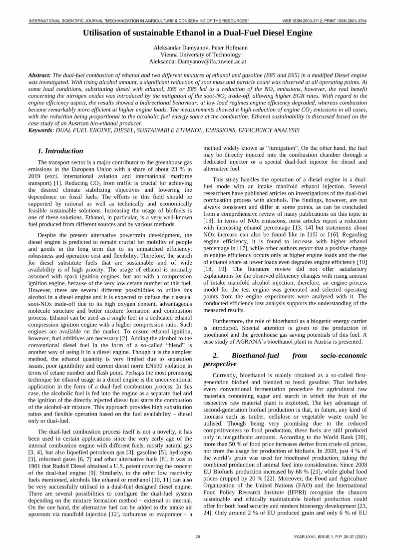
As a biofuel producer, AGRANA has to provide the results of
the greenhouse gas savings through external certifications in
accordance to the International Sustainability and Carbon
Certification (ISCC); Fig. 1 and Fig. 2.
Fig. 1 GHG shares calculated in accordance to EU Directive 2009/28/EC
for bioethanol from different raw materials; starch slurry 1 calculation
INTERNATIONAL SCIENTIFIC JOURNAL "MECHANIZATION IN AGRICULTURE & CONSERVING OF THE RESOURCES" WEB ISSN 2603-3712; PRINT ISSN 2603-3704
29 YEAR LXVII, ISSUE 1, P.P. 28-37 (2021)
Page 3
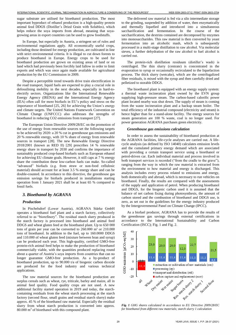
Some countries, like England, accept that no cultivation emissions
are to be accounted for the raw material residual starch slurry
(calculation method ISCC EU). The greenhouse gas savings from
bioethanol produced by AGRANA are at least 68 and are certified
by ISCC.
Fig. 2 GHG emissions and reductions calculated in accordance to EU
Directive 2009/28/EC for bioethanol from different raw materials; starch slurry 1 calculation method ISCC EU, starch slurry 2 – ISCC DE
4. Investigated Fuels
Table 1: Properties of the investigated fuels
Fuel notation Diesel EtOH E85 E65
Density [kg/m³] 831 789 782 773
Lower heating value [MJ/kg] 42.68 26.68 29 31.46
Cetane number [-] 54 8 - -
Research octane number [-] - 111 105 101
C-fraction [wt %] 85.4 51.5 56.5 62.8
H-fraction [wt %] 14.2 13.7 12.8 13.8
O-fraction [wt %] 0.4 34.1 29.8 23.3
H/C atomic ratio [-] 1.99 3.2 2.72 2.65
O/C atomic ratio [-] 0.004 0.5 0.4 0.28
gCO2/MJ 73.3 71.22 72.02 73.12
gH2O/MJ 29.94 46.54 40.08 39.69
Table 1 gives an overview of some of the properties of the
tested fuels.
In this study, a certified CEC test diesel fuel was used as a
reference for comparison. Technically pure ethanol was the first
representative of the investigated oxygenated fuels. However, the
intake manifold injected fuel does not necessarily have to be of high
purity – a great advantage lies within the possibility of using lower-
grade ethanol, since even higher water contents had no harmful
impact on the engine. Additionally, E65 and E85 gasoline-ethanol
mixtures were supplied, because their availability at filling stations
is more presumable. E85 (RF-01-08) was delivered by a supplier
and E65 was self-mixed (35 vol% winter quality gasoline RF-04-
03).
5. Test engine and test methodology
Test engine and measurement equipment
A modern in-line four-cylinder diesel engine was modified for
single cylinder operation and used as a test engine. Only the first
cylinder was fired, while the other three were deactivated and their
gas exchange was separated from the gas exchange of the fired
cylinder. The cylinder had a displacement of 537 cm3 and a
compression ratio of 17.5. Bore and stroke were 88 and 88.34 mm,
respectively. The original high-pressure common rail diesel
injection system was equipped with seven-hole nozzle solenoid
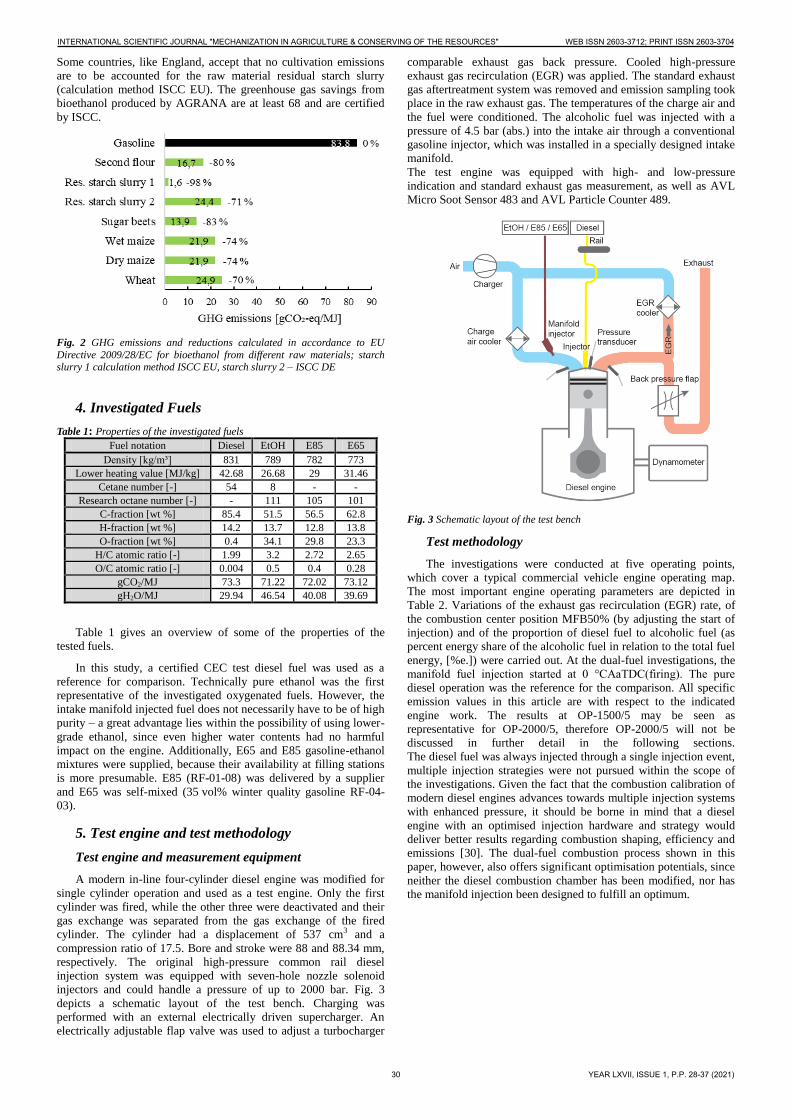
injectors and could handle a pressure of up to 2000 bar. Fig. 3
depicts a schematic layout of the test bench. Charging was
performed with an external electrically driven supercharger. An
electrically adjustable flap valve was used to adjust a turbocharger
comparable exhaust gas back pressure. Cooled high-pressure
exhaust gas recirculation (EGR) was applied. The standard exhaust
gas aftertreatment system was removed and emission sampling took
place in the raw exhaust gas. The temperatures of the charge air and
the fuel were conditioned. The alcoholic fuel was injected with a
pressure of 4.5 bar (abs.) into the intake air through a conventional
gasoline injector, which was installed in a specially designed intake
manifold.
The test engine was equipped with high- and low-pressure
indication and standard exhaust gas measurement, as well as AVL
Micro Soot Sensor 483 and AVL Particle Counter 489.
Fig. 3 Schematic layout of the test bench
Test methodology
The investigations were conducted at five operating points,
which cover a typical commercial vehicle engine operating map.
The most important engine operating parameters are depicted in
Table 2. Variations of the exhaust gas recirculation (EGR) rate, of
the combustion center position MFB50% (by adjusting the start of
injection) and of the proportion of diesel fuel to alcoholic fuel (as
percent energy share of the alcoholic fuel in relation to the total fuel
energy, [%e.]) were carried out. At the dual-fuel investigations, the
manifold fuel injection started at 0 °CAaTDC(firing). The pure
diesel operation was the reference for the comparison. All specific
emission values in this article are with respect to the indicated
engine work. The results at OP-1500/5 may be seen as
representative for OP-2000/5, therefore OP-2000/5 will not be
discussed in further detail in the following sections.
The diesel fuel was always injected through a single injection event,
multiple injection strategies were not pursued within the scope of
the investigations. Given the fact that the combustion calibration of
modern diesel engines advances towards multiple injection systems
with enhanced pressure, it should be borne in mind that a diesel
engine with an optimised injection hardware and strategy would
deliver better results regarding combustion shaping, efficiency and
emissions [30]. The dual-fuel combustion process shown in this
paper, however, also offers significant optimisation potentials, since
neither the diesel combustion chamber has been modified, nor has
the manifold injection been designed to fulfill an optimum.
INTERNATIONAL SCIENTIFIC JOURNAL "MECHANIZATION IN AGRICULTURE & CONSERVING OF THE RESOURCES" WEB ISSN 2603-3712; PRINT ISSN 2603-3704
30 YEAR LXVII, ISSUE 1, P.P. 28-37 (2021)
Page 4
Table 2: Investigated operating points with engine parameters
Operating point OP-
1500/5 1500/15 2000/5 a 2000/20 3000/20
Speed [rpm] 1500 1500 2000 2000 3000
IMEP [bar] 5 15 5 20 20
Power Output [kW]
3.3 10 4.5 17.9
26.8
Rail pressure
[bar] ~670 ~1040 ~800
~1240 ~1400
Int. manifold
pressure [mbar] 1130 2250 1230 2500 2600
∆p exhaust-intake [mbar]
270 500 330 300 300
a Will not be discussed in further detail due to similarity to OP-1500/5
The reproducibility of the measurements was proved by
conducting the experiments three times. The results were carefully
analysed and the middle value was built for the representations.
Simulation model for efficiency loss analysis
Besides the experimental investigations at the engine test bed, a
0D/1D-simulation model of the combustion process was
additionally set up and selected operating points were analysed with
it. The software used was GT-POWER. An important feature of the
simulation is the optional efficiency loss calculation, which
contributes to the understanding of eventual efficiency differences
between the discussed operating modes. The approach used for burn
rate calculation was three pressure analysis (TPA) and required
three measured pressure curves: intake, cylinder and exhaust. The
test bed measurements delivered the input and calibration data for
the simulation.
6. Results of the investigations
In the course of the investigations, at low load, degrading
combustion quality, poor controllability and high cycle variation
determined the maximum possible alternative fuel amount. In this
project, a maximum substitution rate of 60-70 % energy share was
possible with the fuels used. At high loads it was the occurrence of
knock and auto-ignition that prohibited further increase of the
substitution ratio. Nevertheless, at OP-1500/15 still 50-60 %e. (%
energetic) substitution rate was achieved; the corresponding ranges
for OP-2000/20 and OP-3000/20 were measured to be
approximately 40 %e. and 25 %e., respectively. In accordance with
its higher octane number, pure ethanol ensured slightly higher
substitution rates at high load testing, whereas at OP-1500/5 it
failed to provide stable combustion before E65 and E85 did.
Polluting emissions
NOx, soot and particle emissions
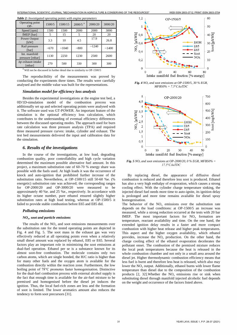
The results of the NOx and soot emissions measurements over
the substitution rate for the tested operating points are depicted in
Fig. 4 and Fig. 5. The soot mass in the exhaust gas was very
effectively reduced at all operating points even when a relatively
small diesel amount was replaced by ethanol, E85 or E65. Several
factors play an important role in minimizing the soot emissions at
dual-fuel operation. Ethanol per se is a substance known for its
almost soot-free combustion. The molecule contains only two
carbon atoms, which are single bonded, the H/C ratio is higher than
for many other fuels and the oxygen atom is available for the
combustion directly within the reaction zone. Furthermore, the low
boiling point of 78°C promotes faster homogenisation. Distinctive
for the dual-fuel combustion process with external alcohol supply is
the fact that enough time is available for the air-fuel mixture to be
premixed and homogenised before the diesel jet induces the
ignition. Thus, the local fuel-rich zones are less and the formation
of soot is limited. The lower aromatics amount also reduces the
tendency to form soot precursors [31].
Fig. 4 NOx and soot emissions at OP-1500/5, 30 % EGR, MFB50% = 7.5°CAaTDC
Fig. 5 NOx and soot emissions at OP-2000/20, 0 % EGR, MFB50% =
17.5°CAaTDC
By replacing diesel, the appearance of diffusive diesel
combustion is reduced and therefore less soot is produced. Ethanol
has also a very high enthalpy of evaporation, which causes a strong
cooling effect. With the cylinder charge temperature sinking, the
injected diesel fuel needs more time to auto-ignite, its ignition delay
is prolonged and more time remains available for diesel spray
homogenisation.
The behavior of the NOx emissions over the substitution rate
depends on the load conditions: at OP-1500/5 an increase was
measured, while a strong reduction occurred at the tests with 20 bar
IMEP. The most important factors for NOx formation are
temperature, reactant availability and time. On the one hand, the
extended ignition delay results in a faster and more compact
combustion with higher heat release and higher peak temperatures.
This aspect and the higher oxygen availability, which ethanol
provides, increase the NOx production. On the other hand, the
charge cooling effect of the ethanol evaporation decelerates the
pollutant onset. The combustion of the premixed mixture reduces
the local peak temperatures because the heat is released in the
whole combustion chamber and not only in a small area around the
diesel jet. Higher thermodynamic combustion efficiency means that
less fuel is burnt and therefore less heat is released, which also may
lower the NOx output. Additionally, ethanol burns with lower flame
temperature than diesel due to the composition of the combustion
products [2, 32].Whether the NOx emissions rise or sink when
substituting diesel through manifold injected alcoholic fuel depends
on the weight and occurrence of the factors listed above.
INTERNATIONAL SCIENTIFIC JOURNAL "MECHANIZATION IN AGRICULTURE & CONSERVING OF THE RESOURCES" WEB ISSN 2603-3712; PRINT ISSN 2603-3704
31 YEAR LXVII, ISSUE 1, P.P. 28-37 (2021)
Page 5
Fig. 6 Particle number-NOx trade-off at OP-1500/5, MFB50% = 7.5°CAaTDC
Fig. 7 Particle number-NOx trade-off at OP-1500/15,
MFB50% = 7.5°CAaTDC
Together with the soot mass, the particle number also dropped
as diesel was replaced by the alternative fuel. By mitigating the
smoke problem of the diesel engine, more EGR could be used as an
in-cylinder measure for further NOx emission reduction – the diesel
typical soot-NOx trade-off was weakened, Fig. 6 and Fig. 7. An
outstanding advantage is visible for dual-fuel operation mode, in
particular for OP-1500/5. In the case of 50 %e. EtOH, at 40 % EGR
and a NOx level of 0.25 g/kWh 3.5 mg/kWh of soot and an FSN of
0.043 was measured.
HC and CO emissions
Compared to the diesel reference operation, the output of
unburnt or partly burnt fuel was found to be considerable at dual-
fuel mode, especially at low loads. The amount of unburnt
hydrocarbons (HC) and carbon monoxide (CO) steeply rose with
the substitution rate. At OP-1500/5 the HC emissions increased by
approx. 2 g/kWh per additional 10 %e. alcoholic fuel. This severe
disadvantage resulted in lower engine efficiency; Fig. 8. The higher
load points provided higher in-cylinder temperatures and pressures,
hence ignition and combustion of the cylinder charge were much
better supported and the incomplete combustion influence on the
engine efficiency diminished.
Efficiency and CO2 emissions
Increasing the substitution rate at OP-1500/5 resulted in a
considerable drop of engine efficiency until approximately 30 %
energy share and affected no significant further changes up to the
maximum possible alcoholic fuel amount; Fig. 8. In contradiction to
this case, a very pronounced efficiency gain was measured at the
medium and high load operating points, as can be seen in Fig. 8 and
Fig. 9. Due to prolonged combustion duration and associated
efficiency loss, the highest efficiency at “diesel only” operation was
measured at a MFB50% of 17.5°CAaTDC for OP-2000/20 and at a
MFB50% of 20°CAaTDC for OP-3000/20. Substituting diesel by
an intake manifold injected alcoholic fuel moved the highest
efficiency combustion center to more advanced MFB50% but, as
could be expected, cylinder peak pressure, pressure rise rate and
nitrogen oxide emissions were very high. Fig. 8 and Fig. 9 also
include an error analysis of the experiments. In order to just outline
the repeatability bandwidth of the experiments regarding the
measured efficiency without overloading the diagrams, not all
measured points are presented with error indicators. As can be seen,
the results at OP-1500/5 show the highest deviations due to the
higher uncertainties when measuring very small fuel flow rates at
the single-cylinder engine.
Fig. 8 Indicated efficiency at OP-1500/5 with 30 % EGR and OP-1500/15 with 15 % EGR, MFB50% = 7.5°CAaTDC
Operating the engine in dual-fuel mode with high alcoholic fuel
energy shares also introduced a much higher tolerance against high
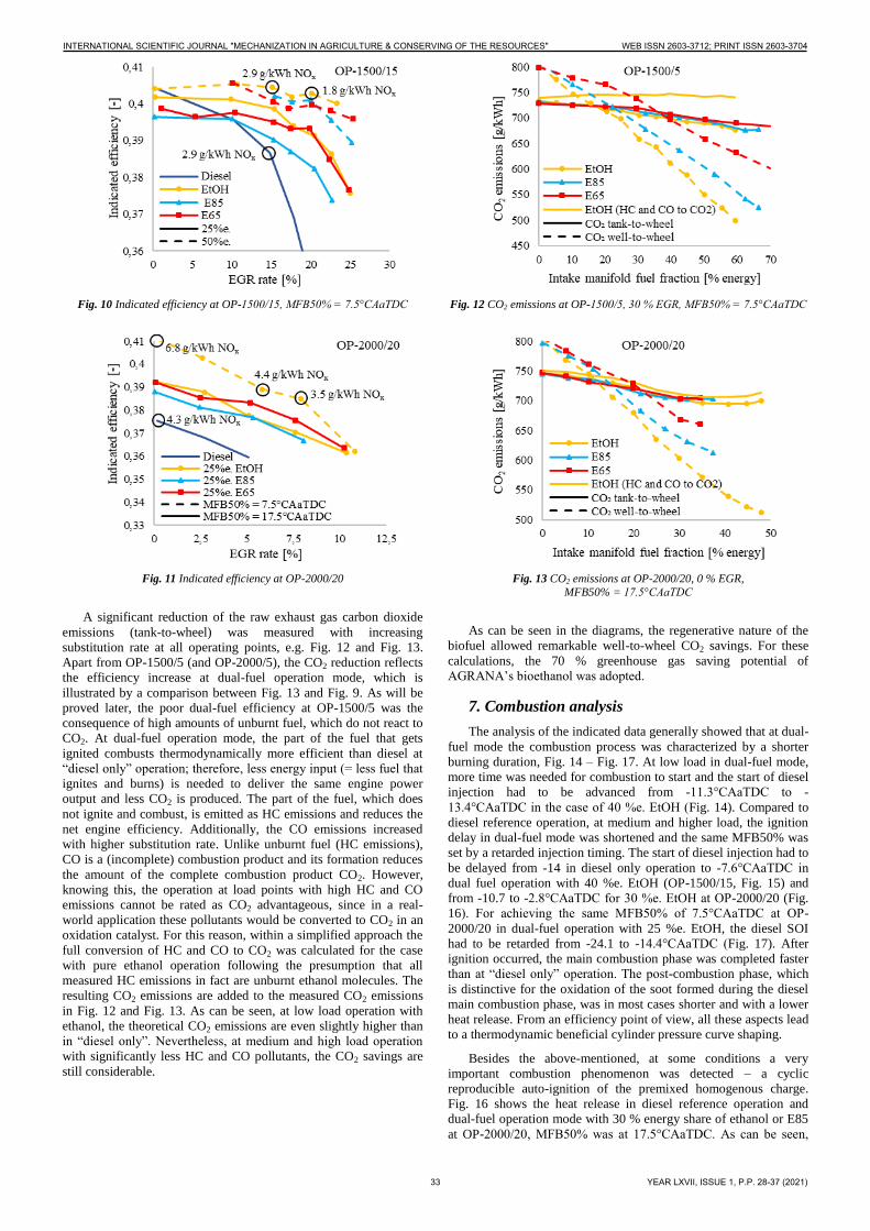
EGR rates; Fig. 10 and Fig. 11. This benefit allowed the application
of higher EGR rates without degrading the efficiency the same way
as in pure diesel operation mode. In Fig. 11, the already mentioned
additional engine efficiency enhancement, which results from
advancing MFB50% when operating in dual-fuel mode at high
loads, is shown together with the measured NOx values for some
interesting points.
Fig. 9 Indicated efficiency at OP-2000/20 with MFB50% = 17.5°CAaTDC
and OP-3000/20 with MFB50% = 20°CAaTDC, 0 % EGR
INTERNATIONAL SCIENTIFIC JOURNAL "MECHANIZATION IN AGRICULTURE & CONSERVING OF THE RESOURCES" WEB ISSN 2603-3712; PRINT ISSN 2603-3704
32 YEAR LXVII, ISSUE 1, P.P. 28-37 (2021)
Page 6
Fig. 10 Indicated efficiency at OP-1500/15, MFB50% = 7.5°CAaTDC
Fig. 11 Indicated efficiency at OP-2000/20
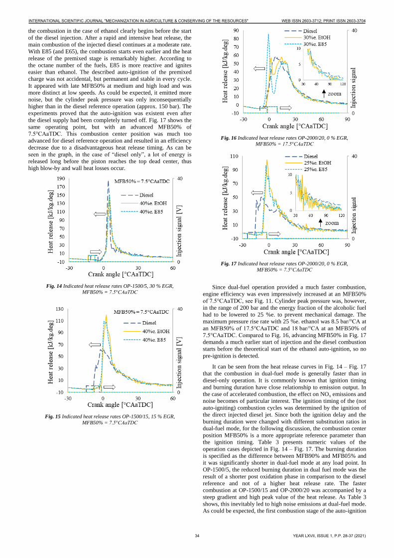
A significant reduction of the raw exhaust gas carbon dioxide
emissions (tank-to-wheel) was measured with increasing
substitution rate at all operating points, e.g. Fig. 12 and Fig. 13.
Apart from OP-1500/5 (and OP-2000/5), the CO2 reduction reflects
the efficiency increase at dual-fuel operation mode, which is
illustrated by a comparison between Fig. 13 and Fig. 9. As will be
proved later, the poor dual-fuel efficiency at OP-1500/5 was the
consequence of high amounts of unburnt fuel, which do not react to
CO2. At dual-fuel operation mode, the part of the fuel that gets
ignited combusts thermodynamically more efficient than diesel at
“diesel only” operation; therefore, less energy input (= less fuel that
ignites and burns) is needed to deliver the same engine power
output and less CO2 is produced. The part of the fuel, which does
not ignite and combust, is emitted as HC emissions and reduces the
net engine efficiency. Additionally, the CO emissions increased
with higher substitution rate. Unlike unburnt fuel (HC emissions),
CO is a (incomplete) combustion product and its formation reduces
the amount of the complete combustion product CO2. However,
knowing this, the operation at load points with high HC and CO
emissions cannot be rated as CO2 advantageous, since in a real-
world application these pollutants would be converted to CO2 in an
oxidation catalyst. For this reason, within a simplified approach the
full conversion of HC and CO to CO2 was calculated for the case
with pure ethanol operation following the presumption that all
measured HC emissions in fact are unburnt ethanol molecules. The
resulting CO2 emissions are added to the measured CO2 emissions
in Fig. 12 and Fig. 13. As can be seen, at low load operation with
ethanol, the theoretical CO2 emissions are even slightly higher than
in “diesel only”. Nevertheless, at medium and high load operation
with significantly less HC and CO pollutants, the CO2 savings are
still considerable.
Fig. 12 CO2 emissions at OP-1500/5, 30 % EGR, MFB50% = 7.5°CAaTDC
Fig. 13 CO2 emissions at OP-2000/20, 0 % EGR,
MFB50% = 17.5°CAaTDC
As can be seen in the diagrams, the regenerative nature of the
biofuel allowed remarkable well-to-wheel CO2 savings. For these
calculations, the 70 % greenhouse gas saving potential of
AGRANA’s bioethanol was adopted.
7. Combustion analysis
The analysis of the indicated data generally showed that at dual-
fuel mode the combustion process was characterized by a shorter
burning duration, Fig. 14 – Fig. 17. At low load in dual-fuel mode,
more time was needed for combustion to start and the start of diesel
injection had to be advanced from -11.3°CAaTDC to -
13.4°CAaTDC in the case of 40 %e. EtOH (Fig. 14). Compared to
diesel reference operation, at medium and higher load, the ignition
delay in dual-fuel mode was shortened and the same MFB50% was
set by a retarded injection timing. The start of diesel injection had to
be delayed from -14 in diesel only operation to -7.6°CAaTDC in
dual fuel operation with 40 %e. EtOH (OP-1500/15, Fig. 15) and
from -10.7 to -2.8°CAaTDC for 30 %e. EtOH at OP-2000/20 (Fig.
16). For achieving the same MFB50% of 7.5°CAaTDC at OP-
2000/20 in dual-fuel operation with 25 %e. EtOH, the diesel SOI
had to be retarded from -24.1 to -14.4°CAaTDC (Fig. 17). After
ignition occurred, the main combustion phase was completed faster
than at “diesel only” operation. The post-combustion phase, which
is distinctive for the oxidation of the soot formed during the diesel
main combustion phase, was in most cases shorter and with a lower
heat release. From an efficiency point of view, all these aspects lead
to a thermodynamic beneficial cylinder pressure curve shaping.
Besides the above-mentioned, at some conditions a very
important combustion phenomenon was detected – a cyclic
reproducible auto-ignition of the premixed homogenous charge.
Fig. 16 shows the heat release in diesel reference operation and
dual-fuel operation mode with 30 % energy share of ethanol or E85
at OP-2000/20, MFB50% was at 17.5°CAaTDC. As can be seen,
INTERNATIONAL SCIENTIFIC JOURNAL "MECHANIZATION IN AGRICULTURE & CONSERVING OF THE RESOURCES" WEB ISSN 2603-3712; PRINT ISSN 2603-3704
33 YEAR LXVII, ISSUE 1, P.P. 28-37 (2021)
Page 7
the combustion in the case of ethanol clearly begins before the start
of the diesel injection. After a rapid and intensive heat release, the
main combustion of the injected diesel continues at a moderate rate.
With E85 (and E65), the combustion starts even earlier and the heat
release of the premixed stage is remarkably higher. According to
the octane number of the fuels, E85 is more reactive and ignites
easier than ethanol. The described auto-ignition of the premixed
charge was not accidental, but permanent and stable in every cycle.
It appeared with late MFB50% at medium and high load and was
more distinct at low speeds. As could be expected, it emitted more
noise, but the cylinder peak pressure was only inconsequentially
higher than in the diesel reference operation (approx. 150 bar). The
experiments proved that the auto-ignition was existent even after
the diesel supply had been completely turned off. Fig. 17 shows the
same operating point, but with an advanced MFB50% of
7.5°CAaTDC. This combustion center position was much too
advanced for diesel reference operation and resulted in an efficiency
decrease due to a disadvantageous heat release timing. As can be
seen in the graph, in the case of “diesel only”, a lot of energy is
released long before the piston reaches the top dead center, thus
high blow-by and wall heat losses occur.
Fig. 14 Indicated heat release rates OP-1500/5, 30 % EGR, MFB50% = 7.5°CAaTDC
Fig. 15 Indicated heat release rates OP-1500/15, 15 % EGR,
MFB50% = 7.5°CAaTDC
Fig. 16 Indicated heat release rates OP-2000/20, 0 % EGR, MFB50% = 17.5°CAaTDC
Fig. 17 Indicated heat release rates OP-2000/20, 0 % EGR, MFB50% = 7.5°CAaTDC
Since dual-fuel operation provided a much faster combustion,
engine efficiency was even impressively increased at an MFB50%
of 7.5°CAaTDC, see Fig. 11. Cylinder peak pressure was, however,
in the range of 200 bar and the energy fraction of the alcoholic fuel
had to be lowered to 25 %e. to prevent mechanical damage. The
maximum pressure rise rate with 25 %e. ethanol was 8.5 bar/°CA at
an MFB50% of 17.5°CAaTDC and 18 bar/°CA at an MFB50% of
7.5°CAaTDC. Compared to Fig. 16, advancing MFB50% in Fig. 17
demands a much earlier start of injection and the diesel combustion
starts before the theoretical start of the ethanol auto-ignition, so no
pre-ignition is detected.
It can be seen from the heat release curves in Fig. 14 – Fig. 17
that the combustion in dual-fuel mode is generally faster than in
diesel-only operation. It is commonly known that ignition timing
and burning duration have close relationship to emission output. In
the case of accelerated combustion, the effect on NOx emissions and
noise becomes of particular interest. The ignition timing of the (not
auto-igniting) combustion cycles was determined by the ignition of
the direct injected diesel jet. Since both the ignition delay and the
burning duration were changed with different substitution ratios in
dual-fuel mode, for the following discussion, the combustion center
position MFB50% is a more appropriate reference parameter than
the ignition timing. Table 3 presents numeric values of the
operation cases depicted in Fig. 14 – Fig. 17. The burning duration
is specified as the difference between MFB90% and MFB05% and
it was significantly shorter in dual-fuel mode at any load point. In
OP-1500/5, the reduced burning duration in dual fuel mode was the
result of a shorter post oxidation phase in comparison to the diesel
reference and not of a higher heat release rate. The faster
combustion at OP-1500/15 and OP-2000/20 was accompanied by a
steep gradient and high peak value of the heat release. As Table 3
shows, this inevitably led to high noise emissions at dual-fuel mode.
As could be expected, the first combustion stage of the auto-ignition
INTERNATIONAL SCIENTIFIC JOURNAL "MECHANIZATION IN AGRICULTURE & CONSERVING OF THE RESOURCES" WEB ISSN 2603-3712; PRINT ISSN 2603-3704
34 YEAR LXVII, ISSUE 1, P.P. 28-37 (2021)
Page 8
at dual-fuel mode with 30 %e. E85 in Fig. 16 produced a higher
noise peak than the combustion with 30 %e. EtOH. Advancing the
center of combustion MFB50% in OP-2000/20 from 17.5 to 7.5
°CAaTDC increased the noise level for both diesel and 25 %e.
EtOH. It can be concluded that the higher noise emissions at middle
and high load in dual-fuel mode are a disadvantage compared to the
diesel reference operation mode.
Table 3: Combustion center position, burning duration, specific NOx and
noise emissions for selected points in both operating modes
MFB50%
Burning duration Noise
ind. NOx
°CAaTDC MFB90% - MFB05% dB g/kWh
OP-1500/5
Diesel 7.5 33.7 95.7 0.68
40%e.EtOH 7.5 27.1 92.1 0.83
40%e.E85 7.5 28.8 92.7 0.78
OP-1500/15
Diesel 7.5 43.8 87 2.94
40%e.EtOH 7.5 30.5 94.3 2.86
40%e.E85 7.5 31.9 94.4 2.92
OP-2000/20
Diesel 17.5 49.6 86.6 4.3
30%e.EtOH 17.5 41.1 92.3 3.37
30%e.E85 17.5 45.7 97.8 3.36
Diesel 7.5 73.8 91 4.59
25%e.EtOH 7.5 41.8 97.2 6.84
25%e.E85 7.5 43.5 97.1 6.82
Higher noise emissions are normally associated with increased
NOx output. While this is an expected correlation within
observations of different combustion shaping at equal operation
points and the same engine and combustion process type, no direct
relation between the heat release shape and the NOx emissions can
be sought when comparing two different combustion concepts like
conventional diesel and dual-fuel operation. The heat release shape
is just one of many parameters that influence the formation of
nitrogen oxides in a combustion engine and these parameters widely
differ for both observed combustion processes. The comparison
between the dual-fuel results measured in OP-2000/20 with late and
advanced MFB50% and similar substitution ratio (25 and 30 %e.)
reveals an extreme increase of the pollutant generation with earlier
combustion center position, Table 3. The noise emissions in
operation with E85, however, were barely changed. The reason for
this behaviour is the similarity of the heat release gradient at the
start of combustion for both MFB50% cases: due to the auto-
ignition, the operation with E85 produced high noise levels already
at a MFB50% of 17.5°CAaTDC. Advancing the combustion center
position in this case did not increase the noise level, but only the
NOx emissions due to higher in-cylinder peak temperature.
8. Efficiency loss analysis
An efficiency loss analysis is shown in Fig. 18 for low, medium
and high load operation. In agreement with the engine test bed
findings, compared to the diesel reference operation, the indicated
efficiency in dual-fuel mode is reduced only at the 5 bar IMEP load
point. The bar chart clearly visualizes the source of the major
efficiency loss – a high percentage of incomplete combustion. At
the other investigated load points, a higher share of incomplete
combustion is also encountered in dual-fuel mode, it is however
significantly lower than at OP-1500/5 and is being
overcompensated by a series of efficiency gains.
Due to the changed fluid composition, the real charge and real
fluid properties losses sink at all dual-fuel operating points. Since
MFB50% and the pressure difference “exhaust – manifold” are held
approximately equal for each pair “diesel only – dual-fuel”, the
losses due to combustion phasing and gas exchange are also
basically identical. The “real burn rate” shares in the diagram prove
the accelerated combustion at dual-fuel mode to be one of the main
reasons for higher efficiency.
Another loss that is generally reduced when operating with
intake manifold alcoholic fuel injection is the wall heat transfer.
Surprisingly, the calculated heat transfer loss at OP-2000/20 is
equal for both combustion processes. The efficiency loss is
calculated by relating the specific particular work loss to the work
that would result from the brought-in fuel energy with no losses at
all (100 % efficiency). The software calculates 2.6 bar mean
effective pressure loss due to heat transfer for the “diesel only” case
and 2.5 bar for the dual-fuel case with 30 %e. ethanol, so both cases
differ by only 0.1 bar. However, dual-fuel mode operation also
requires less fuel energy than diesel reference operation (2.73 vs
2.85 kJ/cycle), so the percentual heat loss share in this case is barely
changed.
Fig. 18 Results of the efficiency loss analysis for three operation points. Comparison between “diesel only” operation mode and dual-fuel operation
It should be noted that the calculated values for wall heat
transfer have to be interpreted with care when comparing stratified
operation (as in pure diesel mode) and partially premixed operation
(as in dual-fuel mode), as the wall heat transfer model used in the 0-
dimensional approach (Woschni Classic) does not account for
stratification effects. Therefore, wall heat loss for stratified
operation tends to be overestimated in comparison to homogenous
(or partly homogenous) operation.
9. Summary/Conclusions
The usage of ethanol and two different mixtures of ethanol and
gasoline (E85 and E65) was investigated on a modified diesel
engine designed to work in a dual-fuel combustion mode with
intake manifold alcohol injection. The maximum ratio of alcohol to
diesel fuel was limited by irregular combustion phenomena like
degrading combustion quality and poor process controllability at
low load and knock as well as auto-ignition at high load. At low
load testing, up to 70 % of the diesel energy could be substituted by
the alcoholic fuels, whereas at high loads the maximum substitution
rate declined to approximately 30 %e. With rising alcohol amount, a
significant reduction of soot mass and particle number was
observed. At some testing points, substituting diesel with ethanol,
E65 or E85 led to a reduction of NOx emissions; however, the real
benefit concerning the nitrogen oxides was introduced by the
mitigation of the soot-NOx trade-off. The indicated engine
INTERNATIONAL SCIENTIFIC JOURNAL "MECHANIZATION IN AGRICULTURE & CONSERVING OF THE RESOURCES" WEB ISSN 2603-3712; PRINT ISSN 2603-3704
35 YEAR LXVII, ISSUE 1, P.P. 28-37 (2021)
Page 9
efficiency was significantly improved with enhanced substitution
ratios at high loads (by up to 6 %), whereas it dropped at low loads
(by approx. 3 %). The combustion process tolerance against high
EGR rates in dual-fuel mode allowed more exhaust gas to be
recirculated without affecting engine efficiency the same negative
way as in “diesel only” operation. The analysis of the indicated
cylinder data revealed that at some high load conditions in dual-fuel
mode, a cyclic reproducible auto-ignition of the premixed charge
occurred. An engine-process simulation model showed that the high
amounts of unburnt fuel at dual-fuel operation were the main reason
for efficiency degradation, whereas the reduced losses due to real
charge composition, real fluid properties, real burn rate and heat
transfer enhanced the efficiency of the engine at dual-fuel mode.
Substituting diesel with manifold injected alcoholic fuels reduced
the engine CO2 emissions at medium and high load operating
points. The catalytic conversion of the high HC and CO emissions
measured at low load testing would eventually lead to higher
tailpipe CO2 emissions at this operating point. A case study of the
bioethanol production by AGRANA demonstrated fuel-related
greenhouse gas saving potentials of up to 72 %. By using this
bioethanol as a second fuel in the dual-fuel designed engine, the
well-to-wheel CO2 emissions could be cut down by almost 40 %.
Conventional biofuels have the potential to contribute to the
mitigation of the problems surrounding energy supply as well as
food and feed production, provided that sustainability and socio-
economic criteria are fulfilled and certified.
10. References
1. European Environment Agency, “Approximated estimates for
greenhouse gas emissions,” https://www.eea.europa.eu/data-
and-maps/data/approximated-estimates-for-greenhouse-gas-
emissions-2, accessed Mai. 2021.
2. Iverfeldt, E., Stalhammar, P., Sarby, H., Ihrfors, C. et al.,
“Sustainable Transportation by Using Ethanol in Diesel
Engines,” Proceedings of the 36th International Vienna Motor
Symposium (1):290-307, 7-8 May 2015, ISBN 978-3-18-
378312-0.
3. Karim, G. A., “Dual-Fuel Diesel Engines,” CRC Press Taylor
& Francis Group, 2015, ISBN 978-1-4987-0308-6.
4. Sprenger, F., Fasching, P., Eichlseder, H., „Erdgas-Diesel
Dual-Direct-Injection – Ein alternatives Brennverfahren zur
signifikanten CO2-Reduzierung,“ H. Tschöke, R. Marohn
(eds); Proceedings of the „10. Tagung Diesel- und
Benzindirekteinspritzung 2016“, 24-25 November 2016,
Berlin, https://doi.org/10.1007/978-3-658-15327-4_22.
5. Lee, J., Chu, S., Kang, J.; Min, K. et al., “Operating strategy
for gasoline/diesel dual-fuel premixed compression ignition in
a light-duty diesel engine,” International Journal of
Automotive Technology 18(6):943-950, December 2017,
https://doi.org/10.1007/s12239-017-0092-7.
6. Damyanov, A., Hofmann, P., Derntl, M., Schüßler, M.,
Pichler, T., Schwaiger, N., Siebenhofer, M., “Regenerative
Oxygen-Containing Diesel Substitute Fuels as an Ecological
Option for Increasing Efficiency and Minimizing Emissions,”
Nikolai Schubert (eds); Proceedings of the 11th International
Colloquium Fuels p. 315-331, Ostfildern, Germany, 27-29
June 2017, ISBN 978-3-943563-32-0.
7. Lau, C. S, “Biogas upgrade through exhaust gas reforming
process for use in CI engines,” Dissertation, University of
Birmingham, 2012.
8. Theinnoi, K., Suksompong, P., Temwutthikun, W., “Engine
Performance of Dual Fuel Operation with In-cylinder Injected
Diesel Fuels and In-Port Injected DME,” 9th International
Conference on Applied Energy, ICAE2017, 21-24 August
2017, Cardiff, UK,
https://doi.org/10.1016/j.egypro.2017.12.072.
9. Diesel, R., “Method of Igniting and Regulating Combustion
for Internal Combustion Engines,” US Patent 673,160, April
1901
10. Zhang, Z. H., Tsang, K. S., Cheung, C. S., Chan, T.L., Yao,
C.D., “Effect of fumigation methanol and ethanol on the
gaseous and particulate emissions of a direct injection diesel
engine,” Atmospheric Environment 45(11):2001-2008, 2011,
https://doi.org/10.1016/j.atmosenv.2010.12.019.
11. Ogawa, H., Shibata, G., Kato, T., Zhao, P., “Dual Fuel Diesel
Combustion with Premixed Ethanol as the Main Fuel,” SAE
Technical Paper 2014-01-2687, 2014,
https://doi.org/10.4271/2014-01-2687.
12. Heuser, B., Kremer, F., Pischinger, S., “An Experimental
Investigation of Dual-Fuel Combustion in a Light Duty Diesel
Engine by In-Cylinder Blending of Ethanol and Diesel,” SAE
Int. J. Engines 9(1):2016, https://doi.org/10.4271/2015-01-
1801.
13. Imran, A., Varman, M., Masjuki, H. H., Kalam, M. A.,
“Review on alcohol fumigation on diesel engine: A viable
alternative dual-fuel technology for satisfactory engine
performance and reduction of environment concerning
emission,” Renewable and Sustainable Energy Reviews
26:739-751, 2013,
http://dx.doi.org/10.1016/j.rser.2013.05.070.
14. Cheung, C. S., Cheng, C., Chan, T. L., Lee, S. C., “Emissions
Characteristics of a Diesel Engine Fueled with Biodiesel and
Fumigation Methanol,” Energy & Fuels 22(2):906-914,
February 2008, https://doi.org/10.1021/ef7003915.
15. Jiang, Q., Ottikkutti, P., VanGerpen, J., VanMeter, D., “The
Effect of Alcohol Fumigation on Diesel Flame Temperature
and Emissions,” SAE Technical Paper 900386, 1990,
https://doi.org/10.4271/900386.
16. Padala, S., Woo, C., Kook, S., Hawkes, E., “Ethanol utilisation
in a diesel engine using dual-fuelling technology,” Fuel
109:597-607, 2013,
http://dx.doi.org/10.1016/j.fuel.2013.03.049.
17. Abu-Quadis, M., Haddad, O., Qudaisat, M., “The effect of
alcohol fumigation on diesel engine performance and
emissions,” Energy Conversion & Management 41(4):389-
399, March 2000; https://doi.org/10.1016/S0196-
8904(99)00099-0.
18. Cheng, C. H., Cheung, C. S., Chan, T. L., Lee, S. C., Yao, C.
D., “Experimental investigation on the performance, gaseous
and particulate emissions of a methanol fumigated diesel
engine,” Science of the Total Environment 389(1):115-124,
January 2008, https://doi.org/10.1016/j.scitotenv.2007.08.041.
19. Zhang, Z. H., Cheung, C. S., Chan, T.L., Yao, C. D.,
“Emission reduction from diesel engine using fumigation
methanol and diesel oxidation catalyst,” Science of the
Total Environment 407(15):4497-4505, 2009,
https://doi.org/10.1016/j.scitotenv.2009.04.036
20. Baffes, J., Dennis A., “Long-Term Drivers of Food Prices,”
Policy Research Working Paper 6455, The World Bank, May
2013.
21. Eurostat, “Primary production of renewable energy by type,”
https://ec.europa.eu/eurostat/web/products-datasets/-/ten00081,
accessed Nov. 2018.
22. Food and Agriculture Organization of the United Nations
(FAO), “World Food Situation,” 2017,
http://www.fao.org/worldfoodsituation/foodpricesindex/en/.
23. Food and Agriculture Organization of the United Nations
(FAO), “Impacts of Bioenergy on Food Security; Guidance for
Assessment and Response at National and Project Levels,”
Environment and Natural Resources Working Paper No. 52,
Rome, 2012, ISBN 978-92-5-107151-9.
24. Kline, K. L., Msangi, S., Dale, V., Woods, J. et al.,
“Reconciling food security and bioenergy: Priorities for
action,” GCB Bioenergy 9(3):557-576, 2016,
http://dx.doi.org/10.1111/gcbb.12366.
25. International Renewable Energy Agency (IRENA), “Global
Energy Transformation: A Roadmap to 2050,”Abu Dhabi,
2018, ISBN 978-92-9260-059-4.
26. International Energy Agency (IRENA), “Market Report Series:
Renewables 2018. Analysis and Forecasts to 2023,” Oct. 2018,
ISBN PDF 978-92-64-30684-4.
INTERNATIONAL SCIENTIFIC JOURNAL "MECHANIZATION IN AGRICULTURE & CONSERVING OF THE RESOURCES" WEB ISSN 2603-3712; PRINT ISSN 2603-3704
36 YEAR LXVII, ISSUE 1, P.P. 28-37 (2021)
Page 10
27. United Nations Climate Change, “Ethanol Producers Work
with UN to Accelerate Shift to Low Carbon,” UN Climate
Press Release, 18 Oct. 2018, https://unfccc.int/news/ethanol-
producers-work-with-un-to-accelerate-shift-to-low-carbon.
28. Directive 2009/28/EC of the European parliament and of the
council of 23 April 2009 on the promotion of the use of energy
from renewable sources and amending and subsequently
repealing Directives 2001/77/EC and 2003/30/EC. Available
from: http://eur-lex.europa.eu/.
29. Directive (EU) 2018/2001 of the European parliament and of
the council of 11 December 2018 on the promotion of the use
of energy from renewable sources (recast). Available from:
http://eur-lex.europa.eu/.
30. Vassallo, A., Beatrice, C., Di Blasio, G., Belgiorno, G. et al.,
The Key Role of Advanced, Flexible Fuel Injection Systems to
Match the Future CO2 Targets in an Ultra-Light Mid-Size
Diesel Engine,” SAE Technical Paper 2018-37-0005, 2018,
https://doi.org/10.4271/2018-37-0005.
31. Gargiulo, V., Alfe, M., Blasio, G. D., Beatrice, C., “Chemico-
physical features of soot emitted from a dual-fuel ethanol-
diesel system,” Fuel 150:154-161, 2015,
http://dx.doi.org/10.1016/j.fuel.2015.01.096.
32. Glaude, P. A., Fournet, R., Bounaceur, R., Moliere, M.,
“Adiabatic flame temperature from biofuels and fossil fuels
and derived effect on NOx emissions,” Fuel Processing
Technology 91(2):229-235, 2010,
doi:10.1016/j.fuproc.2009.10.002.
11. Definitions/Abbreviations
°CAaTDC Crank angle degrees after top dead center
CEC Certified test diesel fuel
DDGS Distiller’s dried grain with solubles
E65 Mixture of 65 vol% ethanol and 35
vol% gasoline
E85 Mixture of 85 vol% ethanol and 15
vol% gasoline
EGR Exhaust gas recirculation
EtOH Ethanol
EU European Union
FSN Filter Smoke Number
GHG Greenhouse gas
GMO Genetically modified organism
IMEP Indicated mean effective pressure
MFB Mass fraction burned
OP Operating point
SOI Start of injection
INTERNATIONAL SCIENTIFIC JOURNAL "MECHANIZATION IN AGRICULTURE & CONSERVING OF THE RESOURCES" WEB ISSN 2603-3712; PRINT ISSN 2603-3704
37 YEAR LXVII, ISSUE 1, P.P. 28-37 (2021)