2005-01-2892 International Space Station Carbon Dioxide Removal Assembly (ISS CDRA) Concepts and Advancements Dina El Sherif Honeywell International,Torrance CA 90504 James C. Knox NASA Marshall Space Flight Center ABSTRACT An important aspect of air revitalization for life support in spacecraft is the removal of carbon dioxide from cabin air. Several types of carbon dioxide removal systems are in use in spacecraft life support. These systems rely on various removal techniques that employ different architectures and media for scrubbing CO, such as permeable membranes, liquid amine, adsorbents, and absorbents. Sorbent systems have been used since the first manned missions. The current state of key technology is the existing International Space Station (ISS) Carbon Dioxide Removal Assembly (CDRA), a system that selectively removes carbon dioxide from the cabin atmosphere. The CDRA system was launched aboard UF-2 in February 2001 and resides in the U.S. Destiny Laboratory module. During the past four years, the CDRA system has operated with varying degrees of success. There have been several approaches to troubleshooting the CDRA system aimed at developing work-around solutions that would minimize the impact on astronaut time required to implement interim solutions. The paper discusses some of the short-term fixes applied to promote hardware life and restore functionality, as well as long-term plans and solutions for improving operability and reliability. The CDRA is a critical piece of life support equipment in the air revitalization system of the ISS, and is demonstrated technology that may ultimately prove well- suited for use in lunar or Mars base, and Mars transit life support applications. INTRODUCTION The existing International Space Station (ISS) Carbon Dioxide Removal Assembly is part of the ISS air revitalization system, providing continuous COPremoval from the cabin atmosphere. CDRA is a regenerative system whose principal operation utilizes 4 beds. Each bed ORU contains a desiccant bed and a CO, sorbent be-ence desiccantladsorbent bed ORU. The system relies on one desiccant bed to condition the air prior to entry into the adsorbent bed. The adsorbent bed selectively removes the COP,and the air travels through the second desiccant adsorbent bed to replace the humidity. The CDRA system is a water-save system in contrast to the 2-bed Skylab system, which vented adsorbed water overboard. The U.S. Skylab Program successfully demonstrated the use of zeolite molecular sieves in regenerative CO, removal by using a two-bed subsystem that performed for over 4100 hours without failure. (1). While cabin air processing, one carbon dioxide removal bed is in the process of regeneration. Regeneration is accomplished using pressure/thermal swing methodology. First, the two-stage pump removes the free air from the adsorbent bed and returns it to the cabin, reducing oxygen ullage. Then Kapton heaters integrated within the adsorbent bed raise the zeolite temperature, and space vacuum creates a low, partial pressure driving the carbon dioxide gas overboard. Dayhight and continuous day power cycle is overlapped with the operating cycle. In the dayhight power cycle, the carbon dioxide adsorbent bed heaters are only allowed to be powered on during the day portion of the cycle In the current open-loop configuration, carbon dioxide is removed from the cabin and discharged overboard. The gases lost during venting must be replaced, and thus represent a consumable. By comparison, a closed-loop CDRA system could selectively remove carbon dioxide from the cabin air supply, and the concentrated CO, would be routed to a carbon dioxide reduction system, where the oxygen would be recovered, thereby reducing the consumables. This is an important aspect of long-term life support necessary to the success of lunar or Mars base or Mars Transit vehicle programs. https://ntrs.nasa.gov/search.jsp?R=20050210002 2018-06-24T00:04:31+00:00Z
Transcript
2005-01-2892
International Space Station Carbon Dioxide Removal Assembly
(ISS CDRA) Concepts and Advancements
Dina El Sherif Honeywell International, Torrance CA 90504
James C. Knox NASA Marshall Space Flight Center
ABSTRACT
An important aspect of air revitalization for life support in spacecraft is the removal of carbon dioxide from cabin air. Several types of carbon dioxide removal systems are in use in spacecraft life support. These systems rely on various removal techniques that employ different architectures and media for scrubbing CO,, such as permeable membranes, liquid amine, adsorbents, and absorbents. Sorbent systems have been used since the first manned missions. The current state of key technology is the existing International Space Station (ISS) Carbon Dioxide Removal Assembly (CDRA), a system that selectively removes carbon dioxide from the cabin atmosphere. The CDRA system was launched aboard UF-2 in February 2001 and resides in the U.S. Destiny Laboratory module. During the past four years, the CDRA system has operated with varying degrees of success. There have been several approaches to troubleshooting the CDRA system aimed at developing work-around solutions that would minimize the impact on astronaut time required to implement interim solutions.
The paper discusses some of the short-term fixes applied to promote hardware life and restore functionality, as well as long-term plans and solutions for improving operability and reliability.
The CDRA is a critical piece of life support equipment in the air revitalization system of the ISS, and is demonstrated technology that may ultimately prove well- suited for use in lunar or Mars base, and Mars transit life support applications.
INTRODUCTION
The existing International Space Station (ISS) Carbon Dioxide Removal Assembly is part of the ISS air revitalization system, providing continuous COP removal from the cabin atmosphere. CDRA is a regenerative system whose principal operation utilizes 4 beds. Each
bed ORU contains a desiccant bed and a CO, sorbent be-ence desiccantladsorbent bed ORU. The system relies on one desiccant bed to condition the air prior to entry into the adsorbent bed. The adsorbent bed selectively removes the COP, and the air travels through the second desiccant adsorbent bed to replace the humidity.
The CDRA system is a water-save system in contrast to the 2-bed Skylab system, which vented adsorbed water overboard. The U.S. Skylab Program successfully demonstrated the use of zeolite molecular sieves in regenerative CO, removal by using a two-bed subsystem that performed for over 4100 hours without failure. (1).
While cabin air processing, one carbon dioxide removal bed is in the process of regeneration. Regeneration is accomplished using pressure/thermal swing methodology. First, the two-stage pump removes the free air from the adsorbent bed and returns it to the cabin, reducing oxygen ullage. Then Kapton heaters integrated within the adsorbent bed raise the zeolite temperature, and space vacuum creates a low, partial pressure driving the carbon dioxide gas overboard. Dayhight and continuous day power cycle is overlapped with the operating cycle. In the dayhight power cycle, the carbon dioxide adsorbent bed heaters are only allowed to be powered on during the day portion of the cycle
In the current open-loop configuration, carbon dioxide is removed from the cabin and discharged overboard. The gases lost during venting must be replaced, and thus represent a consumable. By comparison, a closed-loop CDRA system could selectively remove carbon dioxide from the cabin air supply, and the concentrated CO, would be routed to a carbon dioxide reduction system, where the oxygen would be recovered, thereby reducing the consumables. This is an important aspect of long-term life support necessary to the success of lunar or Mars base or Mars Transit vehicle programs.
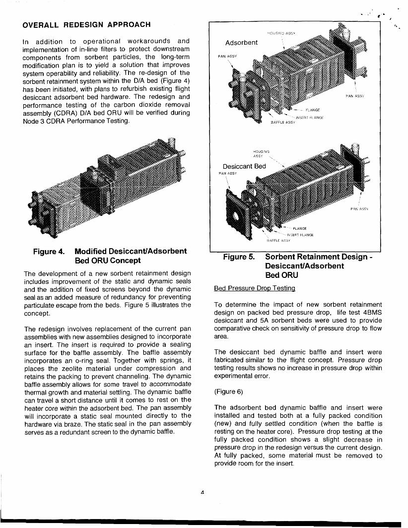
The D/A bed ORU is a critical component of the CDRA system for removing cafbon dioxide. There are two D/A bed ORU's per CDRA system. Each of the ORU's was verified via system level Protoflight testing. By performing the verification at an integrated level, individual ORU's need not be tested. To support ORU- level Acceptance testing of the D/A bed spares, the program must develop ORU-level tests to use in lieu of the existing system-level CDRA tests. Figure 2 depicts the D/A bed ORU.
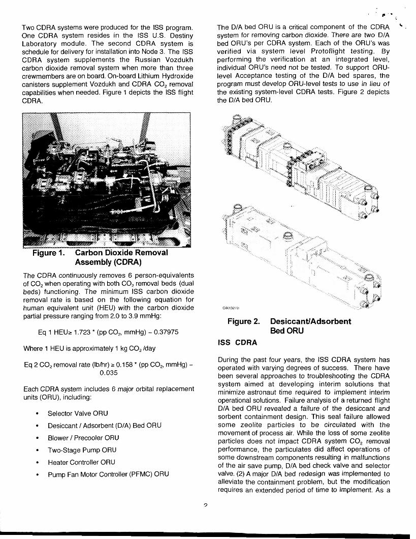
' . Two CDRA systems were produced for the ISS program. One CDRA system resides in the ISS U.S. Destiny Laboratory module. The second CDRA system is schedule for delivery for installation into Node 3. The ISS CDRA system supplements the Russian Vozdukh carbon dioxide removal system when more than three crewmembers are on board. On-board Lithium Hydroxide canisters supplement Vozdukh and CDRA CO, removal capabilities when needed. Figure 1 depicts the ISS flight CDRA.
Figure 1. Carbon Dioxide Removal Assembly (CDRA)
The CDRA continuously removes 6 person-equivalents of CO, when operating with both C02 removal beds (dual beds) functioning. The minimum ISS carbon dioxide removal rate is based on the following equation for human equivalent unit (HEU) with the carbon dioxide partial pressure ranging from 2.0 to 3.9 mmHg:
Each CDRA system includes 6 major orbital replacement units (ORU), including:
Selector Valve ORU
Blower / Precooler ORU
Two-Stage Pump ORU
Heater Controller ORU
Desiccant / Adsorbent (D/A) Bed ORU
Pump Fan Motor Controller (PFMC) ORU
Figure 2. DesiccantlAdsorbent Bed ORU
ISS CDRA
During the past four years, the ISS CDRA system has operated with varying degrees of success. There have been several approaches to troubleshooting the CDRA system aimed at developing interim solutions that minimize astronaut time required to implement interim operational solutions. Failure analysis of a returned flight D/A bed ORU revealed a failure of the desiccant and sorbent containment design. This seal failure allowed some zeolite particles to be circulated with the movement of process air. While the loss of some zeolite particles does not impact CDRA system CO, removal performance, the particulates did affect operations of some downstream components resulting in malfunctions of the air save pump, D/A bed check valve and selector valve. (2) A major D/A bed redesign was implemented to alleviate the containment problem, but the modification requires an extended period of time to implement. As a
3
L
h 4.v * , .1
..<,' result, several interim measures were adopted for on orbit operations to work through this extended redesign period.
The team devised an operational mode that allows continued operation that takes advantage of the system's redundant architecture. A single-bed operation workaround allows a ground controller to isolate a bed from space vacuum during any half-cycle in which that bed is not operating properly, such as when the check valve fails open. During single-bed operation, the system provides 3 person-equivalent removal capabilities. To date, this work around has been implemented on several half-cycles during CDRA operations, however a majority of the time the CDRA has functioned with 100% capability, i.e., dual bed operation.
As a . short-term hardware-based solution, the team decided to install in-line filters to capture any uncontained zeolite particulate material. In-line filters would extend the life of the selector valve ORU's and the two-stage air save pump. Combined filter testing and analysis resulted in an optimal filter design that met system specifications, i.e., flow and pressure drop(3). It also provided the program with an early system hardware protection feature. MSFC supported the development portion of the in-line filter by providing design data to Honeywell International, the manufacturer of the CDRA and filters. The filter design allowed installation without system modifications through placement of in-line filters in locations having relatively easy crew access. To date, astronauts have installed three 0.5-inch filters and three of the four 1.5-inch filters in the CDRA system while on orbit. Figure 3 presents a schematic of the CDRA.
Figure 3. CDRA Schematic
OVERALL REDESIGN APPROACH
In addition to operational workarounds and implementation of in-line filters to protect downstream components from sorbent particles, the long-term modification plan is to yield a solution that improves system operability and reliability. The re-design of the sorbent retainment system within the DIA bed (Figure 4) has been initiated, with plans to refurbish existing flight desiccant adsorbent bed hardware. The redesign and performance testing of the carbon dioxide removal assembly (CDRA) D/A bed ORU will be verified during Node 3 CDRA Performance Testing.
Figure 4. Modified DesiccantlAdsorbent Bed ORU Concept
The development of a new sorbent retainment design includes improvement of the static and dynamic seals and the addition of fixed screens beyond the dynamic seal as an added measure of redundancy for preventing particulate escape from the beds. Figure 5 illustrates the concept.
The redesign involves replacement of the current pan assemblies with new assemblies designed to incorporate an insert. The insert is required to provide a sealing surface for the baffle assembly. The baffle assembly incorporates an O-ring seal. Together with springs, it places the zeolite material under compression and retains the packing to prevent channeling. The dynamic baffle assembly allows for some travel to accommodate thermal growth and material settling. The dynamic baffle can travel a short distance until it comes to rest on the heater core within the adsorbent bed. The pan assembly will incorporate a static seal mounted directly to the hardware via braze. The static seal in the pan assembly serves as a redundant screen to the dynamic baffle.
BAFFLE A S S I
HCIJSING
Desiccant Bed -\
3
INSERT FLANGE BhFFLE 4 S Y
~
Figure 5. Sorbent Retainment Design - DesiccantlAdsorbent Bed ORU
Bed Pressure Drop Testing
To determine the impact of new sorbent retainment design on packed bed pressure drop, life test 4BMS desiccant and 5A sorbent beds were used to provide comparative check on sensitivity of pressure drop to flow area.
The desiccant bed dynamic baffle and insert were fabricated similar to the flight concept. Pressure drop testing results shows no increase in pressure drop within experimental error.
(Figure 6)
The adsorbent bed dynamic baffle and insert were installed and tested both at a fully packed condition (new) and fully settled condition (when the baffle is resting on the heater core). Pressure drop testing at the fully packed condition shows a slight decrease in pressure drop in the redesign versus the current design. At fully packed, some material must be removed to provide room for the insert.
A
L
- o v ' ,
(Figure 7)
Material is removed to allow the dynamic baffle to be in the proper position representing the fully settle state. Pressure drop testing results shows a decreasing pressure drop over travel for the current design. In the redesign case, the pressure drop remains uniform over baffle travel. This can be explained by the removal of sorbent is likely offset by obstruction of flow area at end of travel.
L
(3) Experimental and Analvtical lnvestication of Pressure Differentials for Clean and Loaded Wire Meshes Used in Zeolite Retention; Knox, James C. ICES 2004- 01 -2544
(Figure 8)
Incorporating the insert and baffle will O-ring will not adversely affect the pressure drop, the pressure drop testing suggests the redesign components will lower the pressure drop across the bed by a small value (5 mmH,O) at nominal flow conditions. The pressure drop results may be an indication that the CO, removal performance impact will also be small.
CONCLUSION
The CDRA is a critical piece of life support equipment in the air revitalization system of the ISS. This paper discussed some of the short-term fixes applied to promote hardware life and restore functionality, as well as long-term plans and solutions for improving operability and reliability. Short-term program goals include completing installation of in-line filters to protect downstream components from sorbent particles. The long-term goal is the development and implementation of a new sorbent retainment design that restores 100% functionality full-time while maintaining reliable system operability. To date, short-term solutions have restored CDRA functionality a majority of the time. The long-term solution will be to improve CDRA functionality to full capability at all times.
ACKNOWLEDGEMENTS
Honeywell would like to thank James C. Knox and NASA Marshall Space Flight Center's (MSFC) support in development of the intine filters and bed pressure drop testing.
REFERENCES
(1) 941396 Molecular Sieve CO, Removal Svstems for Future Missions: Test Results and Alternative Desians M.S. Nacheff-Benedict
(2) International SDace Station ClSS) Environmental Control and Life SUDDO~~ (ECLS) Svstem Overview of Events: Februarv 2002-2004; Gentry, Gregory J. Reysa, Richard P., Williams, Dave E ICES 2004-01 -2383