. . . GTR9 – Draft Working Document of IG GTR9 PH2 Version 1, 04 Sept. 2013 Current GTR9 Text (consolidated version, status 09/2013) Proposed amendments 1. PURPOSE 1.1. The purpose of this global technical regulation is to bring about an im- provement in the construction of certain parts of the front of vehicles which have been identified as causing injury when in collision with a pe- destrian or other vulnerable road user. 1.2. The vehicles to be tested under the regulation are representative of the majority of vehicles in circulation in the urban environment, where there is a greater potential for collision with pedestrians and other vulnerable road users, and include passenger cars, vans and light trucks. 2. APPLICATION / SCOPE 2.1. This global technical regulation (gtr) shall apply to the frontal surfaces of power driven vehicles of category 1-1 with a gross vehicle mass exceed- ing 500 kg; and of category 1-2 with a gross vehicle mass exceeding 500 kg but not exceeding 4,500 kg; and of category 2 with a gross vehicle mass exceeding 500 kg but not exceeding 4,500 kg. 1 However, power driven vehicles of category 1-2 and category 2, where the distance, meas- ured longitudinally on a horizontal plane, between the transverse centre line of the front axle and the R-point of the driver's seat is less than 1,100 1 A contracting party may restrict application of the requirements in its domestic legislation if it decides that such restrict ion is appropriate. GTR9-8-03
Transcript
. . .
GTR9 – Draft Working Document of IG GTR9 PH2
Version 1, 04 Sept. 2013
Current GTR9 Text (consolidated version, status 09/2013)
Proposed amendments
1. PURPOSE
1.1. The purpose of this global technical regulation is to bring about an im-
provement in the construction of certain parts of the front of vehicles
which have been identified as causing injury when in collision with a pe-
destrian or other vulnerable road user.
1.2. The vehicles to be tested under the regulation are representative of the
majority of vehicles in circulation in the urban environment, where there
is a greater potential for collision with pedestrians and other vulnerable
road users, and include passenger cars, vans and light trucks.
2. APPLICATION / SCOPE
2.1. This global technical regulation (gtr) shall apply to the frontal surfaces of
power driven vehicles of category 1-1 with a gross vehicle mass exceed-
ing 500 kg; and of category 1-2 with a gross vehicle mass exceeding 500
kg but not exceeding 4,500 kg; and of category 2 with a gross vehicle
mass exceeding 500 kg but not exceeding 4,500 kg. 1 However, power
driven vehicles of category 1-2 and category 2, where the distance, meas-
ured longitudinally on a horizontal plane, between the transverse centre
line of the front axle and the R-point of the driver's seat is less than 1,100
1 A contracting party may restrict application of the requirements in its domestic legislation if it decides that such restrict ion is appropriate.
GTR9-8-03
- 2 -
. . .
mm, are exempt from the requirements of this regulation. Contracting
Parties can exempt category 1-1 vehicles where the distance, measured
longitudinally on a horizontal plane, between the transverse centre line of
the front axle and the R-point of the driver's seat is less than 1,100 mm
and having the components of the frontal structure that are interchangea-
ble with the above-mentioned category 1-2 and category 2 vehicles.
All definitions of Special Resolution No. 1 shall apply as necessary.
3. DEFINITIONS
When performing measurements as described in this Part, the vehicle
should be positioned in its normal ride attitude.
If the vehicle is fitted with a badge, mascot or other structure, which
would bend back or retract under an applied load of maximum 100 N,
then this load shall be applied before and/or while these measurements are
taken.
Any vehicle component which could change shape or position, other than
suspension components or active devices to protect pedestrians, shall be
set to their stowed position.
For the purposes of this regulation:
3.1. "Adult headform test area" is an area on the outer surfaces of the front
structure. The area is bounded, in the front, by a wrap around distance
(WAD) of 1,700 mm and, at the rear, by the rear reference line for adult
headform and, at each side, by the side reference line.
3.2. "A-pillar" means the foremost and outermost roof support extending from
- 3 -
. . .
the chassis to the roof of the vehicle.
3.3. "Bonnet leading edge" means the edge of the front upper outer structure
of the vehicle, including the bonnet and wings, the upper and side mem-
bers of the headlight surrounds and any other attachments. The reference
line identifying the position of the bonnet leading edge is defined by its
height above the ground reference plane and by the horizontal distance
separating it from the bumper (bumper lead).
3.4. "Bonnet leading edge height" means, at any point on the bonnet leading
edge, the vertical distance between the ground reference plane and the
bonnet leading edge reference line at that point.
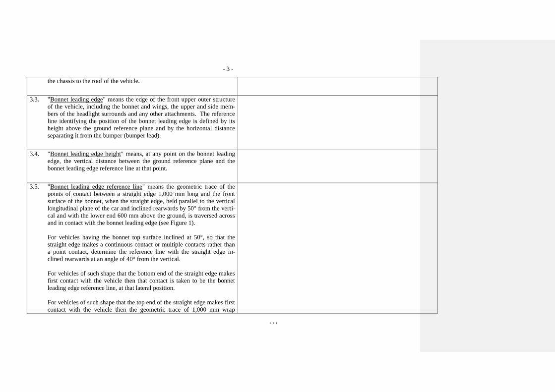
3.5. "Bonnet leading edge reference line" means the geometric trace of the
points of contact between a straight edge 1,000 mm long and the front
surface of the bonnet, when the straight edge, held parallel to the vertical
longitudinal plane of the car and inclined rearwards by 50° from the verti-
cal and with the lower end 600 mm above the ground, is traversed across
and in contact with the bonnet leading edge (see Figure 1).
For vehicles having the bonnet top surface inclined at 50°, so that the
straight edge makes a continuous contact or multiple contacts rather than
a point contact, determine the reference line with the straight edge in-
clined rearwards at an angle of 40° from the vertical.
For vehicles of such shape that the bottom end of the straight edge makes
first contact with the vehicle then that contact is taken to be the bonnet
leading edge reference line, at that lateral position.
For vehicles of such shape that the top end of the straight edge makes first
contact with the vehicle then the geometric trace of 1,000 mm wrap
- 4 -
. . .
around distance, will be used as bonnet leading edge reference line at that
lateral position.
The top edge of the bumper shall also be regarded as the bonnet leading
edge if it is contacted by the straight edge during this procedure.
3.6. "Bonnet rear reference line" means the geometric trace of the most rear-
ward points of contact between a 165 mm diameter sphere and the front
structure of the vehicle when the sphere is traversed across the front struc-
ture of the vehicle while maintaining contact with the windscreen (see
Figure 2). The wiper blades and arms are removed during this process.
Where the bonnet rear reference line and the side reference line do not
intersect, the bonnet rear reference line should be extended and/or modi-
fied using a semi-circular template, of radius 100 mm. The template
should be made of a thin flexible sheet material that easily bends to a sin-
gle curvature in any direction. The template should, preferably, resist
double or complex curvature where this could result in wrinkling. The
recommended material is a foam backed thin plastic sheet to allow the
template to "grip" the surface of the vehicle. The template should be
marked up with four points "A" through "D", as shown in Figure 3, while
the template is on a flat surface.
The template should be placed on the vehicle with Corners "A" and "B"
coincident with the side reference line. Ensuring these two corners re-
main coincident with the side reference line, the template should be slid
progressively rearwards until the arc of the template makes first contact
with the bonnet rear reference line. Throughout the process, the template
should be curved to follow, as closely as possible, the outer contour of the
vehicle's bonnet top, without wrinkling or folding of the template. If the
contact between the template and bonnet rear reference line is tangential
and the point of tangency lies outside the arc scribed by points "C" and
- 5 -
. . .
"D", then the bonnet rear reference line is extended and/or modified to
follow the circumferential arc of the template to meet the bonnet side ref-
erence line, as shown in Figure 4.
If the template cannot make simultaneous contact with the bonnet side
reference line at points "A" and "B" and tangentially with the bonnet rear
reference line, or the point at which the bonnet rear reference line and
template touch lies within the arc scribed by points "C" and "D", then ad-
ditional templates should be used where the radii are increased progres-
sively in increments of 20 mm, until all the above criteria are met.
3.7. "Bonnet top" is the area which is bounded by (a), (b) and (c) as follows:
(a) the bonnet leading edge reference line;
(b) the bonnet rear reference line;
(c) the side reference lines.
3.8. "Bumper" means the front, lower, outer structure of a vehicle. It includes
all structures that are intended to give protection to a vehicle when in-
volved in a low speed frontal collision and also any attachments to this
structure. The reference height and lateral limits of the bumper are identi-
fied by the corners and the bumper reference lines.
3.9. "Bumper lead" means for any longitudinal section of a vehicle, the hori-
zontal distance in the vehicle longitudinal plane between the upper bump-
er reference line and the bonnet leading edge reference line
3.10. "Bumper test area" means the frontal surface of the bumper limited by
two longitudinal vertical planes intersecting the corners of the bumper and
moved 66 mm parallel and inboard of the corners of the bumpers.
- 6 -
. . .
3.11. "Centre of the knee" of the lower legform impactor is defined as the point
about which the knee effectively bends.
3.12. "Child headform test area" is an area on the outer surfaces of the front
structure. The area is bounded, in the front, by the front reference line for
child headform, and, at the rear, by the WAD1700 line, and by the side
reference lines.
3.13. "Corner of bumper" means the vehicle's point of contact with a vertical
plane which makes an angle of 60° with the vertical longitudinal plane of
the car and is tangential to the outer surface of the bumper (see Figure 5).
3.14. "Femur" of the lower legform impactor is defined as all components or
parts of components (including flesh, skin covering, damper, instrumenta-
tion and brackets, pulleys, etc. attached to the impactor for the purpose of
launching it) above the level of the centre of the knee.
3.15. "Front reference line for child headform" means the geometric trace as
described on the vehicle front structure using a WAD1000 line. In the
case of vehicles where the wrap around distance to the bonnet leading
edge reference line, is more than 1,000 mm at any point, then the bonnet
leading edge reference line will be used as the front reference line for
child headform at that point.
3.16. "Front structure" means all outer structures of the vehicle except the
windscreen, the windscreen header, the A-pillars and structures rearward
of these. It therefore includes, but is not limited to, the bumper, the bon-
net, wings, scuttle, wiper spindles and lower windscreen frame.
- 7 -
. . .
3.17. "Ground reference plane" means a horizontal plane, either real or imagi-
nary, that passes through the lowest points of contact for all tyres of a ve-
hicle while the vehicle is in its normal ride attitude. If the vehicle is rest-
ing on the ground, then the ground level and the ground reference plane
are one and the same. If the vehicle is raised off the ground such as to al-
low extra clearance below the bumper, then the ground reference plane is
above ground level.
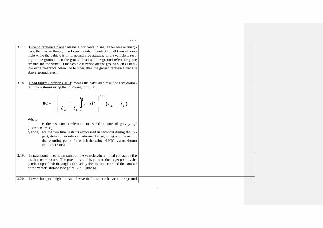
3.18. "Head Injury Criterion (HIC)" means the calculated result of accelerome-
ter time histories using the following formula:
HIC = HPCt t
a dt t tt
t
1
2 1
2 5
2 1
1
2
.
( )
Where:
a is the resultant acceleration measured in units of gravity "g"
(1 g = 9.81 m/s²);
t1 and t2 are the two time instants (expressed in seconds) during the im-
pact, defining an interval between the beginning and the end of
the recording period for which the value of HIC is a maximum
(t2 - t1 ≤ 15 ms)
3.19. "Impact point" means the point on the vehicle where initial contact by the
test impactor occurs. The proximity of this point to the target point is de-
pendent upon both the angle of travel by the test impactor and the contour
of the vehicle surface (see point B in Figure 6).
3.20. "Lower bumper height" means the vertical distance between the ground
- 8 -
. . .
reference plane and the lower bumper reference line, with the vehicle po-
sitioned in its normal ride attitude.
3.21. "Lower bumper reference line" means the lower limit to significant points
of pedestrian contact with the bumper. It is defined as the geometric trace
of the lowermost points of contact between a straight edge 700 mm long
and the bumper, when the straight edge, held parallel to the vertical longi-
tudinal plane of the car and inclined forwards by 25° from the vertical, is
traversed across the front of the car, while maintaining contact with the
ground and with the surface of the bumper (see Figure 7).
3.22. "Normal ride attitude" means the vehicle positioned on a flat horizontal
surface with its mass in running order (as defined in Annex 3, paragraph 3
of Special Resolution No. 1), with the tyres inflated to manufacturer rec-
ommended pressures, the front wheels in the straight-ahead position and
with a passenger mass (as defined in Annex 3, paragraph 6.2. of Special
Resolution No. 1) placed on the front passenger seat. The front seats are
placed at the nominal mid-track position. The suspension shall be set in
normal running condition as specified by the manufacturer for a speed of
40 km/h.
3.23. "Rear reference line for adult headform" means a geometric trace as de-
scribed on the front structure of the vehicle using a WAD2100 line.
"[3.23 The assessment interval (AI) of the flexible lower
legform impactor is defined and limited by the time
of first contact of the flexible lower legform im-
pactor with the vehicle and the timing of the last ze-
ro crossing of all femur and tibia segments after
their first local maximum subsequent to any mar-
ginal value of 15 Nm, within their particular com-
mon zero crossing phases. The AI is identical for all
bone segments and knee ligaments. In case of not all
tibia [and/or] femur bending moments having a ze-
- 9 -
. . .
ro crossing during the common zero crossing phase,
the time history curves are shifted downwards until
all bending moments are crossing zero. The down-
wards shift is to be applied for the determination of
the AI only.]"
Paragraph 3.23 to 3.31., renumber as paragraphs 3.24. to 3.32.
3.24. "Side reference line" means the geometric trace of the highest points of
contact between a straight edge 700 mm long and the sides of the vehicle,
when the straight edge, held parallel to the transverse vertical plane of the
vehicle and inclined inwards by 45°, is traversed down, and maintains
contact with the sides of the front structure (see Figure 8).
"[3.24 Primary reference marks" means holes, surfaces,
marks and identification signs on the vehicle body.
The type of reference mark used and the vertical
(Z) position of each mark relative to the ground
shall be specified by the vehicle manufacturer ac-
cording to the running conditions specified in para-
graph 3.22. These marks shall be selected such as to
be able to easily check the vehicle front and rear
ride heights and vehicle attitude.
If the primary reference marks are found to be
within ± 25 mm of the design position in the vertical
(Z) axis, then the design position shall be considered
to be the normal ride height. If this condition is met,
either the vehicle shall be adjusted to the design po-
sition, or all further measurements shall be adjust-
ed, and tests performed, to simulate the vehicle be-
ing at the design position.]"
Paragraphs 3.24 (former) to 3.32., renumber as
paragraphs 3.25. to 3.33.
3.25. "Target point" means the intersection of the projection of the headform
longitudinal axis with the front surface of the vehicle (see point A in Fig-
ure 6.).
- 10 -
. . .
3.26. "Tibia" of the lower legform impactor is defined as all components or
parts of components (including flesh, skin covering, instrumentation and
brackets, pulleys, etc. attached to the impactor for the purpose of launch-
ing it) below the level of the centre of the knee. Note that the tibia as de-
fined includes allowances for the mass, etc., of the foot.
3.27. "Upper bumper reference line" means the upper limit to significant points
of pedestrian contact with the bumper. For vehicles with an identifiable
bumper structure it is defined as the geometric trace of the uppermost
points of contact between a straight edge and the bumper, when the
straight edge, held parallel to the vertical longitudinal plane of the car and
inclined rearwards by 20° to the vertical, is traversed across the front of
the car, while maintaining contact with the surface of the bumper (see
Figure 9).
For vehicles with no identifiable bumper structure it is defined as the ge-
ometric trace of the uppermost points of contact between a straight edge
700 mm long and the bumper area, when the straight edge, held parallel to
the vertical longitudinal plane of the car and inclined rearwards by 20°
from the vertical is traversed across the front of the car, while maintaining
contact with the ground and with the surface of the bumper area (see Fig-
ure 9).
3.28. "Wrap Around Distance (WAD)" means the geometric trace described on
the outer surface of the vehicle front structure by one end of a flexible
tape, when it is held in a vertical longitudinal plane of the vehicle and
traversed across the front structure. The tape is held taut throughout the
operation with one end held at the same level as the ground reference
plane, vertically below the front face of the bumper and the other end held
in contact with the front structure (see Figure 10). The vehicle is posi-
- 11 -
. . .
tioned in the normal ride attitude.
This procedure shall be followed, using alternative tapes of appropriate
lengths, to describe wrap around distances of 1,000 mm (WAD1000), of
1,700 mm (WAD1700) and of 2,100 mm (WAD2100).
3.29. "Windscreen" means the frontal glazing of the vehicle situated between
the A-pillars.
600 mm
Bonnet leading edge
reference line
Straight edge
1,000 mm long
50°
Figure 1: Bonnet leading edge reference line (see paragraph 3.5.)
- 12 -
. . .
Sphere
Bonnet rear
reference line
Figure 2: Bonnet rear reference line. (see paragraph 3.6.)
Corner ‘A’
Corner ‘B’
Point ‘C’
Point ‘D’
R100 mm
Corner ‘A’
Corner ‘B’
45°
Point ‘C’
Point ‘D’
45°
Figure 3: Template (see paragraph 3.6.)
- 13 -
. . .
Figure 4: Marking of intersection between bonnet rear and side reference lines
(see paragraph 3.6.)
Corner of bumper
Vertical plane
- 14 -
. . .
Figure 5: Corner of bumper (see paragraph 3.13.)
A: Target point
B: Impact point
θ : Impact angle
θ
B
A
Figure 6: Impact and target point (see paragraphs 3.19. and 3.25.)
- 15 -
. . .
Figure 7: Lower bumper reference line, LBRL (see paragraph 3.21.)
LBRL LBRL LBRL
25
Straight edge
700mm Long
- 16 -
. . .
Bonnet side
reference line
Straight edge
700 mm long
45°
Figure 8: Side reference line (see paragraph 3.24.)
- 17 -
. . .
20°
Straight edge
700 mm long
UBRL UBRL UBRL
Figure 9: Upper bumper reference line, UBRL (see paragraph 3.27.)
- 18 -
. . .
Wrap around
distance
Figure 10: Wrap around distance measurement (see paragraph 3.28.)
4. GENERAL REQUIREMENTS
This global technical regulation specifies the following tests to verify
compliance of vehicles.
4.1. Legform test to bumper:
For vehicles with a lower bumper height of less than 425 mm the re-
quirements of paragraph 4.1.1. shall be applied.
For vehicles with a lower bumper height which is greater than, or equal
to 425 mm and less than 500 mm the requirements of either paragraph
4.1.1. or 4.1.2., at the choice of the manufacturer, shall be applied.
- 19 -
. . .
For vehicles with a lower bumper height of greater than, or equal to,
500 mm the requirements of paragraph 4.1.2. shall be applied.
4.1.1. Lower legform to bumper:
To verify compliance with the performance requirements as specified in
paragraph 5.1.1., both the test impactor specified in paragraph 6.3.1.1.
and the test procedures specified in paragraph 7.1.1. shall be used.
4.1.2. Upper legform to bumper:
To verify compliance with the performance requirements as specified in
paragraph 5.1.2., both the test impactor specified in paragraph 6.3.1.2.
and the test procedures specified in paragraph 7.1.2. shall be used.
4.2. Child headform impact:
To verify compliance with the performance requirements as specified in
paragraph 5.2.1., both the test impactor specified in paragraph 6.3.2.1.
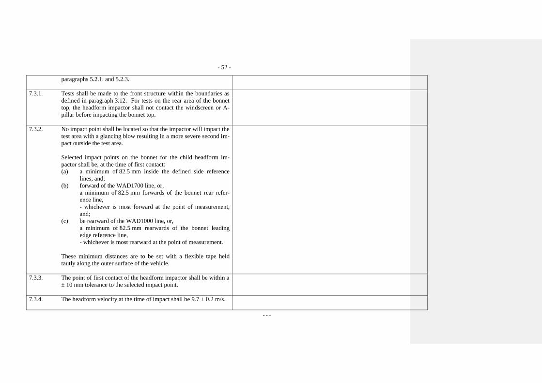
and the test procedures specified in paragraphs 7.2. and 7.3. shall be used.
4.3. Adult headform impact:
To verify compliance with the performance requirements as specified in
paragraph 5.2.2., both the test impactor specified in paragraph 6.3.2.2. and
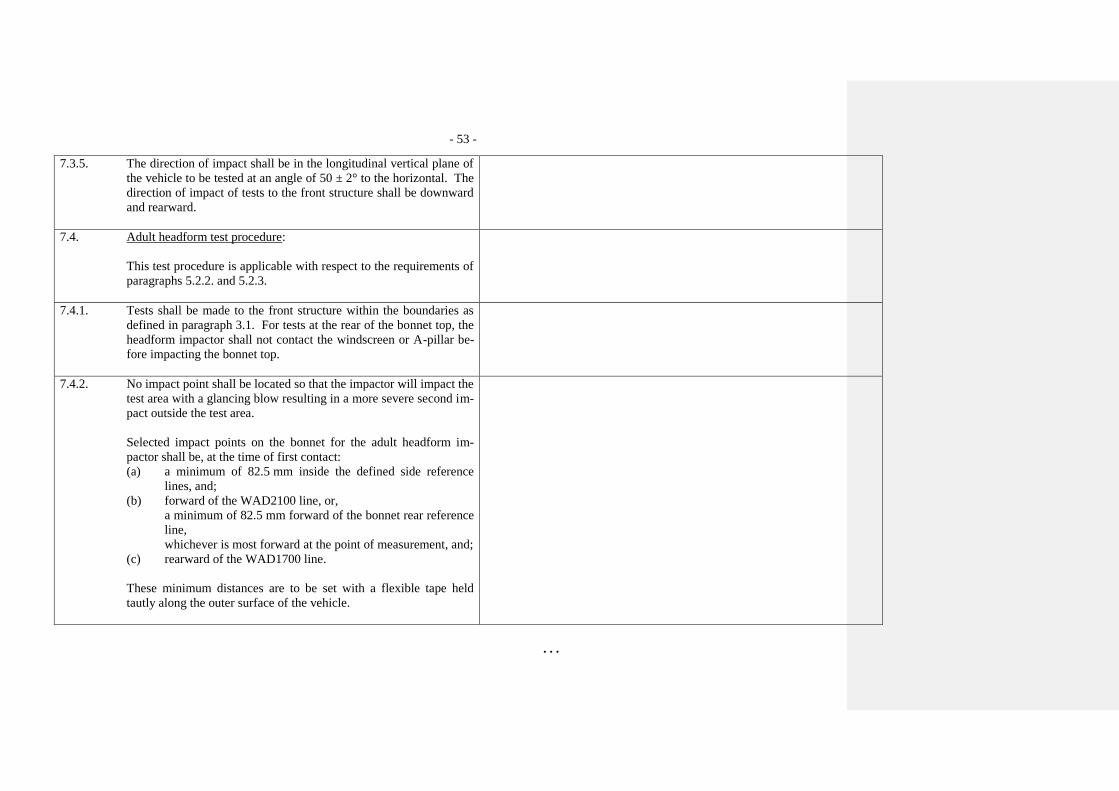
the test procedures specified in paragraphs 7.2. and 7.4. shall be used.
- 20 -
. . .
5. PERFORMANCE REQUIREMENTS
5.1. Legform to bumper:
5.1.1. When tested in accordance with paragraph 7.1.1. (lower legform to
bumper), the maximum dynamic knee bending angle shall not ex-
ceed 19°, the maximum dynamic knee shearing displacement shall
not exceed 6.0 mm, and the acceleration measured at the upper end
of the tibia shall not exceed 170g. In addition, the manufacturer
may nominate bumper test widths up to a maximum of 264 mm in
total where the acceleration measured at the upper end of the tibia
shall not exceed 250g.
"5.1.1. When tested in accordance with paragraph 7.1.1.
(lower legform to bumper), the absolute value of
the maximum dynamic medial collateral
ligament elongation at the knee shall not exceed
22 mm, and the absolute value of dynamic
bending moments at the tibia shall not exceed
340 Nm. The maximum dynamic anterior
cruciate ligament and posterior cruciate ligament
elongation shall not exceed 13 mm. In addition,
the manufacturer may nominate bumper test
widths up to a maximum of 264 mm in total
where the absolute value of the tibia bending
moment shall not exceed 380 Nm. A Contracting
Party may restrict application of the relaxation
zone requirement in its domestic legislation if it
decides that such restriction is appropriate.
When tested in accordance with paragraph 7.1.1.
(lower legform to bumper), the maximum dynamic
knee bending angle shall not exceed 19°, the
maximum dynamic knee shearing displacement
shall not exceed 6.0 mm, and the acceleration
measured at the upper end of the tibia shall not
exceed 170g. In addition, the manufacturer may
nominate bumper test widths up to a maximum of
264 mm in total where the acceleration measured at
the upper end of the tibia shall not exceed 250g."
- 21 -
. . .
5.1.2. When tested in accordance with paragraph 7.1.2. (upper legform to
bumper), the instantaneous sum of the impact forces with respect to
time shall not exceed 7.5 kN and the bending moment on the test
impactor shall not exceed 510 Nm.
5.2. Headform tests
5.2.1. Child headform to the front structure:
When tested in accordance with paragraphs 7.2. and 7.3. the HIC
shall comply with paragraph 5.2.3.
5.2.2. Adult headform to the front structure:
When tested in accordance with paragraph 7.2. and 7.4. the HIC
shall comply with paragraph 5.2.3.
5.2.3. The HIC recorded shall not exceed 1,000 over a minimum of one
half of the child headform test area and 1,000 over two thirds of the
combined child and adult headform test areas. The HIC for the re-
maining areas shall not exceed 1,700 for both headforms.
In case there is only a child headform test area, the HIC recorded
shall not exceed 1,000 over two thirds of the test area. For the re-
maining area the HIC shall not exceed 1,700.
5.2.4. Splitting of headform test zone
5.2.4.1. The manufacturer shall identify the zones of the bonnet top where
the HIC must not exceed 1,000 (HIC1000 Zone) or 1,700 (HIC1700
Zone) (see Figure 11).
- 22 -
. . .
Figure 11: Example of marking of HIC1000 zone and HIC1700 zone
5.2.4.2. Marking of the "bonnet top" impact area as well as "HIC1000
Zone" and "HIC1700 Zone" will be based on a drawing supplied by
the manufacturer, when viewed from a horizontal plane above the
vehicle that is parallel to the vehicle horizontal zero plane. A suffi-
cient number of x and y co-ordinates shall be supplied by the manu-
facturer to mark up the areas on the actual vehicle while considering
the vehicle outer contour in the z direction.
5.2.4.3. The areas of "HIC1000 Zone" and "HIC1700 Zone" may consist of
several parts, with the number of these parts not being limited. The
determination of the impacted zone is done by the first contact point
of the headform with the "bonnet top."
5.2.4.4. The calculation of the surface of the impact area as well as the sur-
face areas of "HIC1000 Zone" and "HIC1700 Zone" shall be done
HIC1000
Zone
HIC1700
Zone
- 23 -
. . .
on the basis of a projected bonnet when viewed from a horizontal
plane parallel to the horizontal zero plane above the vehicle, on the
basis of the drawing data supplied by the manufacturer.
6. TEST SPECIFICATIONS
6.1. General test conditions
6.1.1. Temperature and humidity
At the time of testing, the test facility and the vehicle or sub-system
shall have a relative humidity of 40 percent ± 30 percent and stabi-
lized temperature of 20 + 4 ºC.
6.1.2. Impact test site
The test site shall consist of a flat, smooth and hard surface with a
slope not exceeding 1 percent.
6.2. Preparation of the vehicle
6.2.1. Either a complete vehicle, or a cut-body, adjusted to the following
conditions shall be used for the test.
6.2.1.1. The vehicle shall be in its normal ride attitude, and shall be either
securely mounted on raised supports or at rest on a flat horizontal
surface with the parking brake applied.
6.2.1.2. The cut-body shall include, in the test, all parts of the vehicle front
structure, all under-bonnet components and all components behind
the windscreen that may be involved in a frontal impact with a vul-
nerable road user, to demonstrate the performance and interactions
- 24 -
. . .
of all the contributory vehicle components. The cut-body shall be
securely mounted in the normal vehicle ride attitude.
6.2.2. All devices designed to protect vulnerable road users when impact-
ed by the vehicle shall be correctly activated before and/or be active
during the relevant test. It shall be the responsibility of the manu-
facturer to show that any devices will act as intended in a pedestrian
impact.
6.2.3. For vehicle components which could change shape or position, oth-
er than active devices to protect pedestrians, and which have more
than one fixed shape or position shall require the vehicle to comply
with the components in each fixed shape or position.
6.3. Test impactor specifications
6.3.1. Legform impactors:
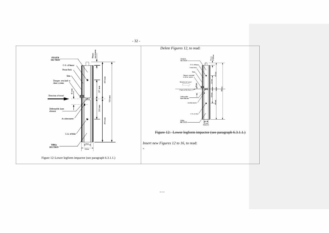
6.3.1.1. Lower legform impactor:
The lower legform impactor shall consist of two foam covered rigid
segments, representing femur (upper leg) and tibia (lower leg),
joined by a deformable, simulated knee joint. The overall length of
the impactor shall be 926 ± 5 mm, having a required test mass of
13.4 ± 0.2 kg (see Figure 12). Dimensions of the various parts are
detailed in Figure 12.
Brackets, pulleys, etc. attached to the impactor for the purpose of
launching it, may extend the dimensions shown in Figure 12.
"6.3.1.1. Flexible lower Lower legform impactor:"
The flexible lower legform impactor shall consist
of flesh, flexible long bone segments
(representing femur and tibia), and a knee joint
as shown in Figure 12.
The overall length of the impactor shall be 928 ±
3 mm, having a required mass of 13.2 ± 0.7 kg
including flesh. The length of the femur, knee
joint, and tibia shall be 339 ± 2 mm, 185 ± 1 mm,
and 404 ± 2 mm respectively. The knee joint
centre position shall be 94 ± 1 mm from the top
of the knee joint.
Brackets, pulleys, protectors, connection parts,
- 25 -
. . .
etc. attached to the impactor for the purpose of
launching and/or protecting may extend beyond
the dimensions shown in Figure 12 and Figure
13.
The lower legform impactor shall consist of two
foam covered rigid segments, representing femur
(upper leg) and tibia (lower leg), joined by a
deformable, simulated knee joint. The overall
length of the impactor shall be 926 ± 5 mm, having
a required test mass of 13.4 ± 0.2 kg (see Figure 12).
Brackets, pulleys, etc. attached to the impactor for
the purpose of launching it, may extend the
dimensions shown in Figure 12. “
6.3.1.1.1. The diameter of the femur and tibia shall be 70 ± 1 mm and both
shall be covered by foam flesh and skin. The foam flesh shall be 25
mm thick foam type CF-45 or equivalent. The skin shall be made
of neoprene foam, faced with 0.5 mm thick nylon cloth on both
sides, with an overall thickness of 6 mm.
6.3.1.1.1. The cross-sectional shape perpendicular to the
Z-axis of the femur and tibia main bodies shall
be 90 ± 2 mm in width along the Y-axis,
and 84 ± 1 mm in width along the X-axis as
shown in Figure 13 (a). The impact face shall be
30 ± 1 mm in radius, 30 ± 1 mm in width along
the Y-axis, and 48 ± 1 mm in width along the X-
axis as shown in Figure 13 (a).
The diameter of the femur and tibia shall be 70 ± 1
mm and both shall be covered by foam flesh and
skin. The foam flesh shall be 25 mm thick foam
type CF-45 or equivalent. The skin shall be made of
neoprene foam, faced with 0.5 mm thick nylon cloth
on both sides, with an overall thickness of 6 mm.
- 26 -
. . .
6.3.1.1.2. The knee joint shall be fitted with deformable knee elements from
the same batch as those used in the certification tests.
6.3.1.1.2. The cross-sectional shape perpendicular to the
Z-axis of the knee joint shall be 108 ± 2 mm in
width along the Y-axis, and 118 ± 1 mm in width
along the X-axis as shown in Figure 13 (b). The
impact face shall be 103 ± 1 mm in radius, 12 ± 1
mm in width along the Y-axis, and 86 ± 1 mm in
width along the X axis as shown in Figure 13 (b).
The knee joint shall be fitted with deformable knee
elements from the same batch as those used in the
certification tests.
6.3.1.1.3. The total masses of the femur and tibia shall be 8.6 ± 0.1 kg
and 4.8 ± 0.1 kg respectively, and the total mass of the impactor
shall be 13.4 ± 0.2 kg. The centre of gravity of the femur and tibia
shall be 217 ± 10 mm and 233 ± 10 mm from the centre of the knee
respectively. The moment of inertia of the femur and tibia, about a
horizontal axis through the respective centre of gravity and perpen-
dicular to the direction of impact, shall be 0.127 ± 0.010 kgm² and
0.120 ± 0.010 kgm² respectively.
6.3.1.1.3. The masses of the femur and tibia without
flesh, including the connection part to the knee
joint, shall be 2.46 ± 0.12 kg and 2.64 ± 0.13 kg
respectively. The mass of the knee joint without
flesh shall be 4.28 ± 0.21 kg. The total mass of the
femur, knee joint and tibia shall
be 9.38 ± 0.47 kg.
The centre of gravity of the femur and tibia
without flesh, including the connection part to
the knee joint, shall be 159 ± 8 mm and 202 ± 10
mm respectively from the top, but not including
the connection part to the knee joint, of each part
as shown in Figure 12. The centre of gravity of
the knee shall be 92 ± 5 mm from the top of the
knee joint as shown in Figure 12.
The moment of inertia of the femur and tibia
without flesh, including the connection part
inserted to the knee joint, about the X-axis
- 27 -
. . .
through the respective centre of gravity shall
be 0.0325 ± 0.0016 kg m² and 0.0467 ± 0.0023
kgm² respectively. The moment of inertia of the
knee joint about the X axis through the
respective centre of gravity shall
be 0.0180 ± 0.0009 kg m².
The total masses of the femur and tibia shall be 8.6
± 0.1 kg and 4.8 ± 0.1 kg respectively, and the total
mass of the impactor shall be 13.4 ± 0.2 kg. The
centre of gravity of the femur and tibia shall be 217
± 10 mm and 233 ± 10 mm from the centre of the
knee respectively. The moment of inertia of the
femur and tibia, about a horizontal axis through the
respective centre of gravity and perpendicular to the
direction of impact, shall be 0.127 ± 0.010 kgm² and
0.120 ± 0.010 kgm² respectively.
6.3.1.1.4. For each test the impactor shall be fitted with new foam flesh cut
from one of up to four consecutive sheets of foam type CF-45 flesh
material or equivalent, produced from the same batch of manufac-
ture (cut from one block or 'bun' of foam), provided that foam from
one of these sheets was used in the dynamic certification test and
the individual weights of these sheets are within ± 2 percent of the
weight of the sheet used in the certification test.
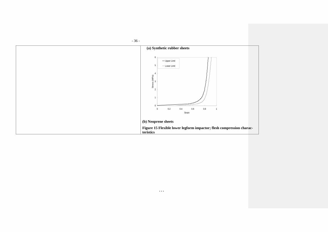
6.3.1.1.4. For each test, the impactor (femur, knee joint,
and tibia) shall be covered by flesh composed of
synthetic rubber sheets (R1, R2) and neoprene
sheets (N1F, N2F, N1T, N2T, N3) as shown in
Figure 14. The sheets are required to have a
compression characteristic as shown in Figure
15. The compression characteristic shall be
checked using the same batch of sheets as those
used for the impactor flesh. The size of the
sheets shall be within the requirements described
in Figure 15.
For each test the impactor shall be fitted with new
foam flesh cut from one of up to four consecutive
sheets of foam type CF-45 flesh material or
- 28 -
. . .
equivalent, produced from the same batch of
manufacture (cut from one block or 'bun' of foam),
provided that foam from one of these sheets was
used in the dynamic certification test and the
individual weights of these sheets are within ± 2
percent of the weight of the sheet used in the
certification test.
6.3.1.1.5. The test impactor or at least the foam flesh shall be stored during a
period of at least four hours in a controlled storage area with a stabi-
lized humidity of 35 percent ± 15 percent and a stabilized tempera-
ture of 20 ± 4°C prior to impactor removal for test. After removal
from the storage the impactor shall not be subjected to conditions
other than those pertaining in the test area.
6.3.1.1.5. The test impactor or at least the flesh shall be
stored for at least four hours in a controlled
storage area with a stabilized temperature
of 20 ± 2°C prior to impactor removal for
calibration. After removal from the storage, the
impactor shall not be subjected to conditions
other than those pertaining in the test area.
The test impactor or at least the foam flesh shall be
stored during a period of at least four hours in a
controlled storage area with a stabilized humidity of
35 percent ± 15 percent and a stabilized temperature
of 20 ± 4°C prior to impactor removal for
calibration. After removal from the storage the
impactor shall not be subjected to conditions other
than those pertaining in the test area.
6.3.1.1.6. Lower legform instrumentation
6.3.1.1.6. Lower legform instrumentation
6.3.1.1.6.1. A uniaxial accelerometer shall be mounted on the non-impacted
side of the tibia, 66 ± 5 mm below the knee joint centre, with its
sensitive axis in the direction of impact.
6.3.1.1.6.1. Four transducers shall be installed in the tibia to
measure bending moments applied to the tibia.
The sensing locations of each of the transducers
- 29 -
. . .
are as follows: tibia-1: 134 ± 1 mm, tibia-2: 214
± 1 mm, tibia-3: 294 ± 1 mm and tibia-4: 374 ± 1
mm below the knee joint centre respectively as
shown in Figure 16. The measurement axis of
each transducer shall be the X-axis of the
impactor.
A uniaxial accelerometer shall be mounted on the
non-impacted side of the tibia, 66 ± 5 mm below the
knee joint centre, with its sensitive axis in the
direction of impact.
6.3.1.1.6.2. A damper shall be fitted to the shear displacement system and may
be mounted at any point on the rear face of the impactor or internal-
ly. The damper properties shall be such that the impactor meets
both the static and dynamic shear displacement requirements and
prevents excessive vibrations of the shear displacement system.
6.3.1.1.6.2. Three transducers shall be installed in the knee
joint to measure elongations of the medial
collateral ligament (MCL), anterior cruciate
ligament (ACL), and posterior cruciate ligament
(PCL). The measurement locations of each
transducer are shown in Figure 16. The
measurement locations shall be within ± 4 mm
along the X-axis from the knee joint centre.
A damper shall be fitted to the shear displacement
system and may be mounted at any point on the rear
face of the impactor or internally. The damper
properties shall be such that the impactor meets both
the static and dynamic shear displacement
requirements and prevents excessive vibrations of
the shear displacement system.
6.3.1.1.6.3. Transducers shall be fitted to measure knee bending angle and knee
shearing displacement.
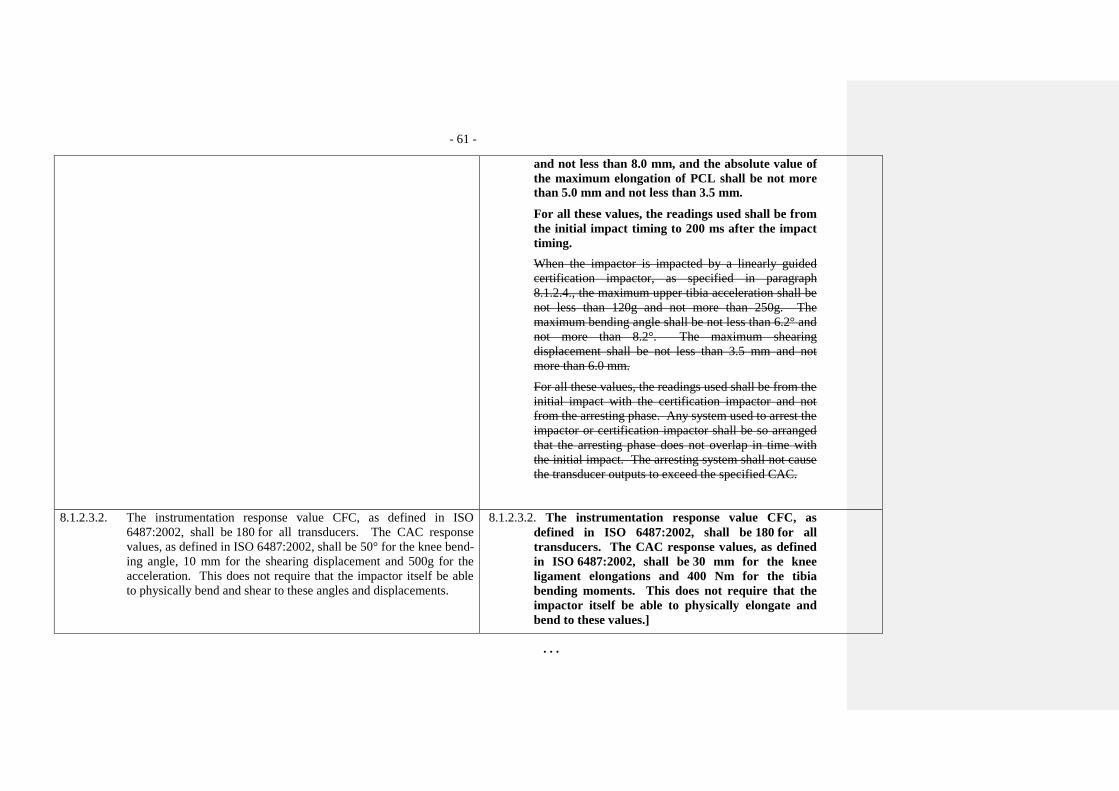
6.3.1.1.6.3. The instrumentation response value channel
frequency class (CFC), as defined in
ISO 6487:2002, shall be 180 for all transducers.
- 30 -
. . .
The CAC response values, as defined in
ISO 6487:2002, shall be 30 mm for the knee
ligament elongations and 400 Nm for the tibia
bending moments. This does not require that the
impactor itself be able to physically elongate or
bend until these values.
Transducers shall be fitted to measure knee bending
angle and knee shearing displacement.
6.3.1.1.6.4. The instrumentation response value channel frequency class (CFC),
as defined in ISO 6487:2002, shall be 180 for all transducers. The
CAC response values, as defined in ISO 6487:2002, shall be 50° for
the knee bending angle, 10 mm for the shearing displacement and
500g for the acceleration. This does not require that the impactor
itself be able to physically bend and shear to these angles and dis-
placements.
6.3.1.1.6.4. The determination of all flexible lower legform
impactor peak tibia bending moments and
ligament elongations shall be limited to the
assessment interval (AI) as defined in paragraph
3.23.
The measurements for the flexible lower legform
impactor shall be taken only for the major
impact with the vehicle prior to the rebound
phase. All maxima occurring during or after the
rebound phase shall be ignored. For example, the
zero crossing after the maximum of the MCL
elongation or of the tibia bending moments shall
be considered as the end of the major impact
with the vehicle.
The instrumentation response value channel
frequency class (CFC), as defined in ISO
6487:2002, shall be 180 for all transducers. The
CAC response values, as defined in ISO 6487:2002,
shall be 50° for the knee bending angle, 10 mm for
the shearing displacement and 500g for the
acceleration. This does not require that the impactor
Kommentiert [RD1]: Text in GRSP-53-29
- 31 -
. . .
itself be able to physically bend and shear to these
8.2.1. The upper legform impactor shall meet the requirements specified
in paragraph 8.2.3. when tested as specified in paragraph 8.2.4.
8.2.2. Calibration
8.2.2.1. The foam flesh for the test impactor shall be stored for a period of at
least four hours in a controlled storage area with a stabilized humid-
ity of 35 ± 10 percent and a stabilized temperature of 20° ± 2°C pri-
or to impactor removal for calibration. The test impactor itself shall
have a temperature of 20° ± 2°C at the time of impact. The temper-
ature tolerances for the test impactor shall apply at a relative humid-
ity of 40 ± 30 percent after a soak period of at least four hours prior
to their application in a test.
8.2.2.2. The test facility used for the calibration test shall have a stabilized
humidity of 40 ± 30 percent and a stabilized temperature of
20° ± 4°C during calibration.
8.2.2.3. Each calibration shall be completed within two hours of when the
impactor to be calibrated is removed from the controlled storage ar-
ea.
8.2.2.4. The relative humidity and temperature of the calibration area shall
be measured at the time of calibration, and recorded in the calibra-
tion report.
8.2.3. Requirements
8.2.3.1. When the impactor is propelled into a stationary cylindrical pendu-
lum the peak force measured in each load transducer shall be not
less than 1.20 kN and not more than 1.55 kN and the difference be-
- 76 -
. . .
tween the peak forces measured in the top and bottom load trans-
ducers shall not be more than 0.10 kN. Also, the peak bending
moment measured by the strain gauges shall not be less than
190 Nm and not more than 250 Nm on the centre position and not
less than 160 Nm and not more than 220 Nm for the outer positions.
The difference between the upper and lower peak bending moments
shall not be more than 20 Nm.
For all these values, the readings used shall be from the initial im-
pact with the pendulum and not from the arresting phase. Any sys-
tem used to arrest the impactor or pendulum shall be so arranged
that the arresting phase does not overlap in time with the initial im-
pact. The arresting system shall not cause the transducer outputs to
exceed the specified CAC.
8.2.3.2. The instrumentation response value CFC, as defined in ISO
6487:2002, shall be 180 for all transducers. The CAC response
values, as defined in ISO 6487:2002, shall be 10 kN for the force
transducers and 1000 Nm for the bending moment measurements.
8.2.4. Test procedure
8.2.4.1. The impactor shall be mounted to the propulsion and guidance sys-
tem, by a torque limiting joint. The torque limiting joint shall be set
so that the longitudinal axis of the front member is perpendicular to
the axis of the guidance system, with a tolerance of ± 2°, with the
joint friction torque set to 675 ± 25 Nm. The guidance system shall
be fitted with low friction guides that allow the impactor to move
only in the specified direction of impact, when in contact with the
pendulum.
8.2.4.2. The impactor mass shall be adjusted to give a mass of 12 ± 0.1 kg,
this mass includes those propulsion and guidance components
- 77 -
. . .
which are effectively part of the impactor during impact.
8.2.4.3. The centre of gravity of those parts of the impactor which are effec-
tively forward of the torque limiting joint, including the extra mass-
es fitted, shall lie on the longitudinal centreline of the impactor,
with a tolerance of ± 10 mm.
8.2.4.4. The impactor shall be certified with previously unused foam.
8.2.4.5. The impactor foam shall not be excessively handled or deformed
before, during or after fitting.
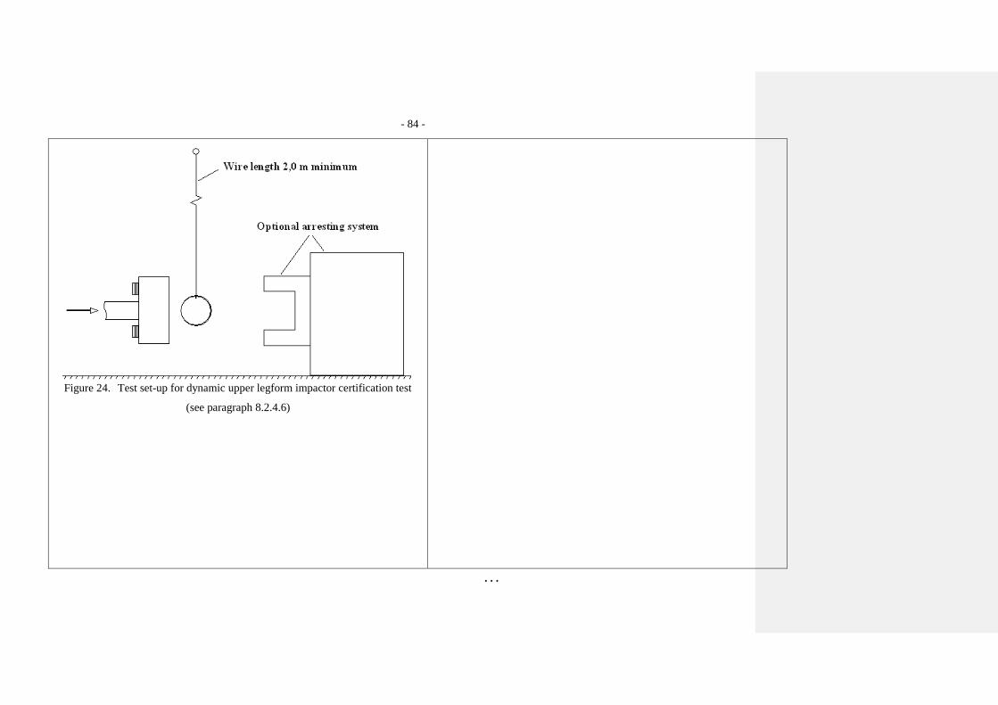
8.2.4.6. The impactor with the front member vertical shall be propelled hor-
izontally at a velocity of 7.1 ± 0.1 m/s into the stationary pendulum
as shown in Figure 24.
Paragraph 8.2.4.6., amend to read:
"… at a velocity of 7.1 ± 0.1 m/s into the stationary
pendulum as shown in Figure 2429."
8.2.4.7. The pendulum tube shall have a mass of 3 ± 0.03 kg, a wall thick-
ness of 3 ± 0.15 mm and an outside diameter of 150 mm +1 mm/-4 mm.
Total pendulum tube length shall be 275 ± 25 mm. The pendulum
tube shall be made from cold finished seamless steel (metal surface
plating is permissible for protection from corrosion), with an outer
surface finish of better than 2.0 micrometer. It shall be suspended
on two wire ropes of 1.5 ± 0.2 mm diameter and of 2.0 m minimum
length. The surface of the pendulum shall be clean and dry. The
pendulum tube shall be positioned so that the longitudinal axis of
the cylinder is perpendicular to the front member (i.e. level), with a
tolerance of 2, and to the direction of impactor motion, with a
tolerance of 2, and with the centre of the pendulum tube aligned
with the centre of the impactor front member, with tolerances of
5 mm laterally and 5 mm vertically.
- 78 -
. . .
8.3. Child and adult headform impactors certification
8.3.1. Drop test
8.3.1.1. Performance criteria
The headform impactors shall meet the requirements specified in
paragraph 8.3.2. when tested as specified in paragraph 8.3.3.
8.3.2. Requirements
8.3.2.1. When the headform impactors are dropped from a height of
376 ± 1 mm in accordance with paragraph 8.3.3. the peak resultant
acceleration measured by one triaxial (or three uniaxial) accelerom-
eter (accelerometers) in the headform impactor shall be:
(a) for the child headform impactor not less than 245g and not more
than 300g;
(b) for the adult headform impactor not less than 225g and not more
than 275g.
The acceleration time curve shall be uni-modal.
8.3.2.2. The instrumentation response values CFC and CAC for each accel-
erometer shall be 1,000 Hz and 500g respectively as defined in ISO
6487:2002.
8.3.2.3. Temperature conditions
The headform impactors shall have a temperature of 20 ± 2°C at the
time of impact. The temperature tolerances shall apply at a relative
humidity of 40 ± 30 percent after a soak period of at least four hours
prior to their application in a test.
- 79 -
. . .
8.3.2.4. After complying with the certification test, each headform impactor
can be used for a maximum of 20 impact tests.
8.3.3. Test procedure
8.3.3.1. The headform impactor shall be suspended from a drop rig as
shown in Figure 25.
Paragraph 8.3.3.1., renumber as paragraph 8.4.3.1. and amend
to read:
"…impactor shall be suspended from a drop rig as shown in
Figure 2530."
8.3.3.2. The headform impactor shall be dropped from the specified height
by means that ensure instant release onto a rigidly supported flat
horizontal steel plate, over 50 mm thick and over 300 x 300 mm
square which has a clean dry surface and a surface finish of between
0.2 and 2.0 micrometers.
8.3.3.3. The headform impactor shall be dropped with the rear face of the
impactor at the test angle specified in paragraph 7.3.5. for the child
headform impactor and in paragraph 7.4.5. for the adult headform
impactor with respect to the vertical as shown in Figure 25. The
suspension of the headform impactor shall be such that it does not
rotate during the fall.
Paragraph 8.3.3.3., amend to read:
"… impactor with respect to the vertical as shown in
Figure 2539. The suspension of …"
8.3.3.4. The drop test shall be performed three times, with the headform
impactor rotated 120° around its symmetrical axis after each test.
Delete (former) Figures 18 to Figure 22, to read:
"
- 80 -
. . .
Figure 18: Force versus angle requirement in static lower legform impactor bending certification
test (see paragraph 8.1.1.2.)
"
Figure 18: Force versus angle requirement in static lower legform impactor
bending certification test (see paragraph 8.1.1.2.)
Figure 19: Force versus displacement requirement in static lower legform
impactor shearing certification test (see paragraph 8.1.1.3.)
- 81 -
. . .
Figure 19: Force versus displacement requirement in static lower legform impactor shearing certi-
fication test (see paragraph 8.1.1.3.)
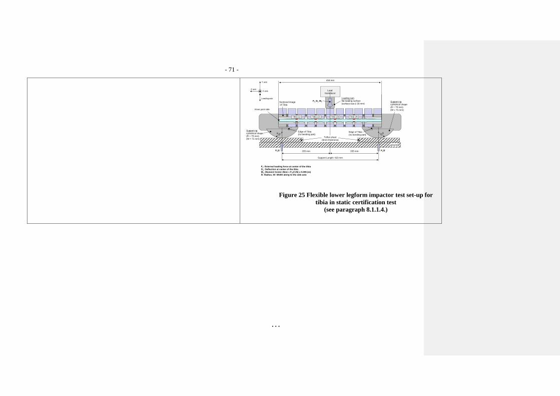
Figure 20: Top View of Test set-up for static lower legform impactor bending certification test
(see paragraph 8.1.1.4.)
Figure 21: Top View of Test set-up for static lower legform impactor shearing certifi-
cation test (see paragraph 8.1.1.5.)
Figure 20: Top View of Test set-up for static lower legform impactor
bending certification test (see paragraph 8.1.1.4.)
Figure 21: Top View of Test set-up for static lower legform
impactor shearing certification test (see paragraph 8.1.1.5.)
- 82 -
. . .
Figure 22: Test set-up for dynamic lower legform impactor certification test
(side view top diagram, view from above bottom diagram) (see paragraph
8.1.2.4.1.)
Figure 22: Test set-up for dynamic lower legform impactor certification test
(side view top diagram, view from above bottom diagram) (see
paragraph 8.1.2.4.1.) "
- 83 -
. . .
Figure 23: Details of dynamic lower legform certification impactor face
(see paragraph 8.1.2.4.2.)
Notes:
1. Saddle may be made as a complete diameter and cut as shown to make
two components.
2. The shaded areas may be removed to give the alternative form shown.
3. Tolerance on all dimensions is 1.0 mm.
Material: Aluminium alloy.
- 84 -
. . .
Figure 24. Test set-up for dynamic upper legform impactor certification test
(see paragraph 8.2.4.6)
- 85 -
. . .
- 86 -
. . .
Figures 23 to Figure 25 (former), renumber as
Figures 29 to Figures 31.
- 87 -
. . .
Figure 25. Test set-up for dynamic headform impactor biofidelity test
(see paragraph 8.3.3.1.)
- - - - -
- 88 -
. . .
Justification
[Based on the results of the TEG as well as IG GTR9 PH2 activities, the IG GTR9 PH2 proposes the above-mentioned draft amendments to the gtr
on pedestrian protection (GTR No. 9)] .
Paragraph 3.23.:
Paragraph 3.24.: [To cover tolerances in built-up, adjustment and alignment of a test vehicle in actual testing it recommended to include the concept of the
primary reference marks, which is already defined in Part A of gtr9 also into in Part B of gtr9. The definitions shall give c lear guidelines and definitions
needed to be able to perform the approval test during the type approval of vehicles and verification testing for self -certification. The proposed definitions
for test vehicles are already incorporated in applicable regulative language for pedestrian protection.]
The text of the gtr no. 9 relevant for this proposal is given below:
Part A, Chapt. 5., (e) Vehicle design position
Page 2
“61. As vehicles come in many variants and modifications, the ride height may vary greatly. Taking into account the differenc es between type approval and
self certification, it is recommended that Contracting Parties take this into account upon national implementation of the gtr . As guidance to Contracting
Parties, the EU addresses this issue by defining the concept of "primary reference marks". This definition (paragraph 2.2 of EU Commission Decision of
23 December 2003) reads:
"Primary reference marks" means holes, surfaces, marks and identification signs on the vehicle body. The type of reference ma rk used and the vertical (Z)
position of each mark relative to the ground shall be specified by the vehicle manufacturer according to the running conditions spec ified in paragraph 2.3.
These marks shall be selected such as to be able to easily check the vehicle front and rear ride heights and vehicle attitude.
62. If the primary reference marks are found to be within ± 25 mm of the design position in the vertical (Z) axis, then the d esign position shall be
considered to be the normal ride height. If this condition is met, either the vehicle shall be adjusted to the design position, or all further measurements
shall be adjusted, and tests performed, to simulate the vehicle being at the design position.”
Insert a new Paragraph 3.30.: new definitions were inserted to introduce the flexible lower legform impactor (editorial)
Paragraph 5.1.1.: replaced by flexible lower legform impactor requirements.
- 89 -
Paragraph 6.3.1.1. to 6.3.1.1.7.2: replaced by flexible lower legform impactor requirements.