INTERNET OF THINGS SYSTEMS SECURITY: BENCHMARKING AND PROTECTION A Dissertation Submitted to the Faculty of Purdue University by Naif Saleh Almakhdhub In Partial Fulfillment of the Requirements for the Degree of Doctor of Philosophy May 2020 Purdue University West Lafayette, Indiana
Transcript
INTERNET OF THINGS SYSTEMS SECURITY: BENCHMARKING AND
PROTECTION
A Dissertation
Submitted to the Faculty
of
Purdue University
by
Naif Saleh Almakhdhub
In Partial Fulfillment of the
Requirements for the Degree
of
Doctor of Philosophy
May 2020
Purdue University
West Lafayette, Indiana
ii
THE PURDUE UNIVERSITY GRADUATE SCHOOL
STATEMENT OF DISSERTATION APPROVAL
Dr. Saurabh Bagchi, Co-Chair
School of Electrical and Computer Engineering
Dr. Mathias Payer, Co-Chair
School of Computer Science
Dr. Milind Kulkarni
School of Electrical and Computer Engineering
Dr. Felix Xiaozhu Lin
School of Electrical and Computer Engineering
Approved by:
Dr. Dimitrios Peroulis
Head of the School of Electrical and Computer Engineering
iii
To my beloved parents, Saleh and Lyla, whose sacrifices and love are the reason for
all my success; and to my dear grandparents, Abdulaziz, Rashid, Dalal, Nora, and
Aljohrah, who are the role models I aspire to be.
iv
ACKNOWLEDGMENTS
This dissertation would not come to fruition without the countless sacrifices and
love from my family. My dear father, who exemplified the value of hard work and
instilled in our family the desire to achieve the highest levels of education. My beloved
mother, whose dedication and rigorous standards of teaching enabled my siblings and
I to succeed. My dear grandmother Dalal, whose faith in me never wavers. My
siblings Dalal, Alanoud, Nora, Abeer, and Abdulaziz, who surround me with love
and happiness. My beloved wife Ghaida, and my dear son Saleh, who sacrificed so
much to accompany me throughout this journey, and filled my heart with love and
joy.
I am grateful to my advisors, Prof. Mathias Payer and Prof. Saurabh Bagchi. I
would not have reached this milestone without their careful reviews, generous feed-
back, and their guidance throughout my time at Purdue. They taught me invaluable
skills that will guide my career for years to come. I would like to extend my thanks
to the members my thesis committee, Prof. Milind Kulkarni and Prof. Felix Lin for
their time and valuable feedback. I am grateful to Abraham Clements for his help,
advice, and the long late nights we worked on papers together. I could not have asked
for a better lab mate than him.
It was my pleasure to be a part of the HexHive group and the Dependable Com-
puting Systems Laboratory (DCSL). I am grateful for all the reviews and feedback
from my peers. I am proud of the direct and honest feedback culture within both
groups that holds the quality of our work to high standards. Special thanks to my lab
mates Mustafa Abdallah, Ashraf Mahgoub, Edgardo Barsallo Yi, and Manish Nagaraj
for the joyful conversations we had together. My deepest thanks to all my friends,
especially Abdulellah Alsaheel, Ali Alsahli, Abdulaziz Alshayban, and Mohammed
Aljardan, for their support throughout my graduate studies.
v
I would like to express my gratitude to King Saud University, and the Saudi Ara-
bian Cultural Mission for funding me throughout my graduate studies. My deepest
thanks to my mentor, Prof. Saleh Alshebeili, who taught me how to preserve and
work effectively under pressure. The lessons and skills I learned from him were in-
valuable to succeed in graduate school. I am also grateful to Prof. Basil AsSadhan,
Prof. Saeed Aldosari, Prof. Aggelos Katsaggelos, and Prof. Goce Trajcevski for their
generous help and guidance during my graduate studies.
I would like to express my heartfelt gratitude to my extended family for their con-
tinuous love and support, especially my uncles, Abdulfattah, Mohammed, Hisham,
Sami, Moath, Mohammed, Saleh, Abdulhameed, Fahd, and my aunts, Moneera, Lat-
ifa, Bodoor, Rihab, Thuraya, Moneera, Rabeaa, and Buthaina.
I am most grateful to my beloved late grandfather Abdulaziz, may Allah (god)
grant him paradise. No one was more instrumental after Allah in completing this
PhD than him. I vividly remember his words inspiring me to pursue a PhD as an
adolescent. Throughout my PhD, especially during tough times, his wise advice and
encouraging words were the ones that lift my spirit, kept me going, and eventually
helped me reach the other shore. His words will always be the shining stars enlight-
ening my path.
Most importantly, I thank almighty Allah for the countless blessings upon me, I
have been lucky beyond any means. I seek his mercy and forgiveness, and pray that
2.1 Overview of MCUS defenses. MCUS type defines whether the defense wasused on bare-metal systems, systems with an OS, or both. Control-flow hi-jacking shows whether the defense protects the return edge, forward edge,or both. Non-control data shows what security guarantees the defense ap-plies to it. Evaluation type shows whether the defense used any availablebenchmark, or customized applications. Using an MCUS evaluation plat-form indicates whether the proposed defense was evaluated on an MCUSdevice. . . . . . . . . . . . . . . . . . . . . . . . . . . . . . . . . . . . . . . 17
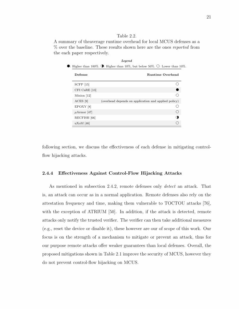
2.2 A summary of theaverage runtime overhead for local MCUS defenses as a% over the baseline. These results shown here are the ones reported fromthe each paper respectively. . . . . . . . . . . . . . . . . . . . . . . . . . . 21
3.1 A summary of defenses for IoT-MCUS with the evaluation type. . . . . . . 29
3.2 A summary of BenchIoT benchmarks and their categorization with respectto task type, and peripherals. . . . . . . . . . . . . . . . . . . . . . . . . . 44
3.3 Summary of BenchIoT memory isolation and control-flow hijacking met-rics for Mbed-µVisor, Remote Attestation (RA) and Data Integrity (DI)defense mechanisms overhead as a percentage of the baseline insecure ap-plications. BM: Bare-metal . . . . . . . . . . . . . . . . . . . . . . . . . . 55
3.4 Comparison of code complexity between BenchIoT and BEEBS. . . . . . . 60
3.5 A Comparison of benchmarks and their categorization with respect to tasktype, networking communication, and peripherals between BenchIoT andother benchmarking suites. . . . . . . . . . . . . . . . . . . . . . . . . . . . 61
4.1 A summary of call instructions in ARMv7-M. . . . . . . . . . . . . . . . . 76
4.2 Analysis of the target set sizes for backward edge type-based CFI. . . . . 103
4.3 Analysis of µRAI transformations and its effect on runtime overhead. N:Number of registers used in the instruction. P: Pipeline refill. P can bebetween 1–3 cycles. . . . . . . . . . . . . . . . . . . . . . . . . . . . . . . 106
4.4 Summary of exception handler SFI protection for store instructions. %shows the percentage of statically protected instructions w.r.t the totalbaseline instructions. . . . . . . . . . . . . . . . . . . . . . . . . . . . . . 106
xi
Table Page
4.5 Summary of µRAI’s Encoder FLT and SR segment configuration comparedto FLTMin of each application. . . . . . . . . . . . . . . . . . . . . . . . 108
4.6 Summary of the segmentation effect on FLT size. . . . . . . . . . . . . . 109
4.8 Summary of the number of call sites instrumented by µRAI, number ofnodes, and edges in the call graph for each application. . . . . . . . . . . 111
xii
LIST OF FIGURES
Figure Page
3.1 An overview of the evaluation workflow in BenchIoT. . . . . . . . . . . . . 31
3.2 Illustration of software layers used in developing BenchIoT benchmarks.BenchIoT provides portable benchmarks by relying on the Mbed platform. 33
3.3 A summary of the BenchIoT metrics. . . . . . . . . . . . . . . . . . . . . . 37
3.5 Summary of BenchIoT performance metrics for µVisor, Remote Attesta-tion, (RA) and Data Integrity (DI) defense mechanisms overhead as a %of the baseline insecure applications. BM: Bare-Metal. . . . . . . . . . . . 53
3.6 Summary of BenchIoT memory utilization metrics for µVisor, RemoteAttestation (RA), and Data Integrity (DI) defense mechanisms overheadas a % over the baseline applications. The size in KB is shown above eachbar. . . . . . . . . . . . . . . . . . . . . . . . . . . . . . . . . . . . . . . . 54
3.7 Summary of BenchIoT comparison of minimizing privileged execution cy-cles for Mbed-µVisor, Remote Attestation (RA) and Data Integrity (DI)defense mechanisms as a % w.r.t the total runtime execution cycles. Theoverhead as a % of the baseline insecure applications is shown above eachbar. BM: Bare-Metal . . . . . . . . . . . . . . . . . . . . . . . . . . . . . . 57
3.8 Summary of power and energy consumption with the BenchIoT bench-marks for the defense mechanisms as a % overhead of the baseline insecureapplications. Power and energy values are shown above each bar in mWand mJ, respectively. BM: Bare-metal . . . . . . . . . . . . . . . . . . . . 59
4.1 Illustration of encoding SR through an XOR chain. Arrows indicate a callsite in the call graph. SR is XORed each time an edge is walked. . . . . . 70
4.2 Illustration µRAI’s protections. µRAI prevents exploiting a vulnerablefunction (e.g., func8) to corrupt the return address or disable the MPU inprivileged execution by coupling its SR encoding with exception handler SFI.71
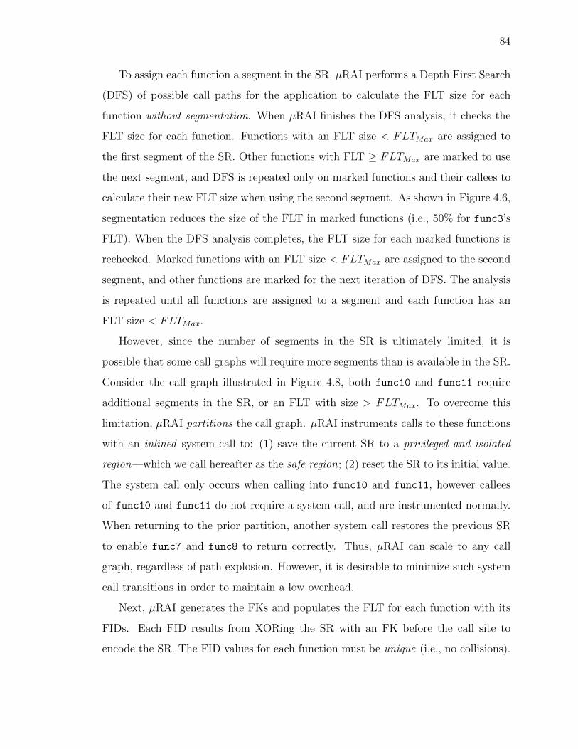
4.6 Illustration of using SR segmentation to reduce path explosion. Segmen-tation reduced the possible SR values for func3 by half. . . . . . . . . . . 82
4.11 An example of µRAI’s instrumentation for recursive call sites. The recur-sion counter shown uses the higher eight bits of LR. . . . . . . . . . . . . . 93
4.13 TLR with SR segmentation. N and M are constants calculated dependingon the function and the start of its segment. . . . . . . . . . . . . . . . . . 95
A.1 Illustration of using SR segmentation to resolve multiple recursion. Red-dashed edges are backward edges (i.e., from higher indexed clones to lowerindexed clones). that trigger a system call to save the SR to the safe regionand reset SR. . . . . . . . . . . . . . . . . . . . . . . . . . . . . . . . . . 133
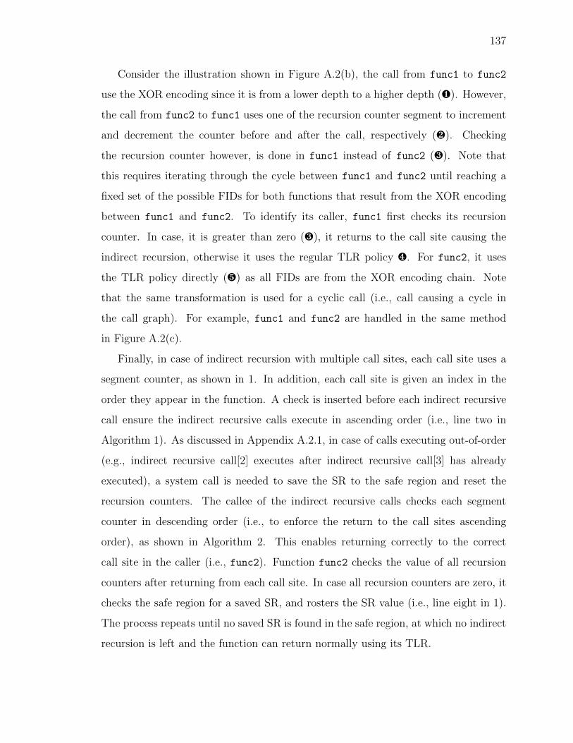
A.2 Illustration of handling indirect recursion. Fig.(a) shows a call graph of twoindirect recursive functions. Fig(b) shows a pseudo code of instrumentingindirect recursive functions. Fig(c) illustrates a cycle of four functions.Functions func1 and func2 are handled in the same method as the firstcase in(a). . . . . . . . . . . . . . . . . . . . . . . . . . . . . . . . . . . . 136
xiv
ABSTRACT
Almakhdhub, Naif Saleh Ph.D., Purdue University, May 2020. Internet of ThingsSystems Security: Benchmarking and Protection. Major Professor: Saurabh Bagchiand Mathias Payer.
Internet of Things (IoT) systems running on Microcontrollers (MCUS) have be-
come a prominent target of remote attacks. Although deployed in security and safety
critical domains, such systems lack basic mitigations against control-flow hijacking
attacks. Attacks against IoT systems already enabled malicious takeover of smart
phones, vehicles, unmanned aerial vehicles, and industrial control systems.
The thesis introduces a systemic analysis of previous defense mitigations to secure
IoT systems. Building off this systematization, we identify two main issues in IoT
systems security. First, efforts to protect IoT systems are hindered by the lack of
realistic benchmarks and evaluation frameworks. Second, existing solutions to protect
from control-flow hijacking on the return edge are either impractical or have limited
security guarantees. This thesis addresses these issues using two approaches.
First, we present BenchIoT, a benchmark suite of five realistic IoT applications
and an evaluation framework that enables automated and extensible evaluation of
14 metrics covering security, performance, memory usage, and energy. BenchIoT
enables evaluating and comparing security mechanisms. Using BenchIoT, we show
that even if two security mechanisms have similarly modest runtime overhead, one
can have undesired consequences on security such as a large portion of privileged user
execution.
Second, we introduce Return Address Integrity (RAI), a novel security mechanism
to prevent all control-flow hijacking attacks targeting return edges, without requiring
special hardware. We design and implement µRAI to enforce the RAI property. Our
xv
results show µRAI has a low runtime overhead of 0.1% on average, and therefore is a
practical solution for IoT systems.
This thesis enables measuring the security IoT systems through standardized
benchmarks and metrics. Using static analysis and runtime monitors, it prevents
control-flow hijacking attacks on return edges with low runtime overhead. Combined,
this thesis advances the state-of-the-art of protecting IoT systems and benchmarking
its security.
1
1. INTRODUCTION
1.1 Motivation
Embedded and IoT systems are deployed in security and privacy critical applica-
tion such as health-care, industrial, Unmanned Ariel Vehicles (UAVs), or smart-home
systems. Estimates project the number of IoT devices to exceed 22 billion devices by
2025 [1]. Unfortunately, this rapid growth is coupled with an alarming number of at-
tacks against IoT devices. Such attacks caused some of the largest Distributed Denial
of Service (DDoS) attacks to date (e.g., Mirai [2] and Hajime [3]), enabled tampering
of critical infrastructure data [4], and allowed malicious takeover of UAVs [5,6] among
others.
This thesis focuses on benchmarking the security of microcontroller-based IoT
systems (IoT-MCUS) and protecting them from remote memory corruption attacks.
Microcontroller systems (MCUS) are a significant portions of deployed IoT devices.
UAVs, smart locks, Engine Control Unit (ECU) gateways, and WiFi System-on-Chip
(SoC) are examples of such systems. MCUS are resource constrained systems: (1)
they have few MBs of Flash and hundreds of KBs of RAM; (2) they run a single stat-
ically linked binary image; (3) they run either with a lightweight Operating System
(OS), or as bare-metal (i.e., without an OS). The single binary image is responsible
for application logic, security configuration, and accessing peripherals. As a result
of their limited resources (e.g., hardware constraints), MCUS cannot use the same
mechanisms from general desktop systems to deploy well known defenses such as
randomization-based defenses (e.g., Address Space Layout Randomization–ASLR),
or stack canaries [7]. However, even if such defenses are deployed, they offer weaker
guarantees. The problem is exacerbated by the poor security practices of MCUS ven-
dors and developers (e.g., not enforcing Data Execution Prevention or W⊕X [8–10]).
2
MCUS can be stand-alone devices, or a component of a larger system. Thus, vul-
nerabilities on MCUS are not confined to the device itself, but can risk the security
of the entire system. For example, hijacking the control of a WiFi SoC can lead to
malicious control of the underlying application processor of a smart phone as shown
by Google’s Project Zero [11]. These attacks gain arbitrary code execution on MCUS
by hijacking the control-flow of the firmware.
As on desktop systems, control-flow hijacking attacks on MCUS originate from
a memory corruption vulnerability violating memory safety or type safety. These
attacks occur by corrupting a code pointer either on the forward edge (i.e., function
pointers, and virtual table pointers) or backward edge (i.e., return addresses). How-
a powerful verifier, able to compute and track all dynamic control-flow traces. There
is no guarantee that such a verifier exists.
In addition, some defenses relying on information hiding [53] assume no versions
of the same diversified firmware exists. This does not guarantee their security as even
diversified firmware can share a ROP payload across different versions [8, 47]. More-
over, such assumption are not easily integrated into deployed systems since vendors
have to keep track of each diversified version (i.e., for code signing and verification).
2.4.2 Security Guarantees of Remote and Local Defenses
The security guarantees of each mechanism depends mainly on its type (i.e., re-
mote or local). The two types can be complemented with each other as each serves
a different goal. Local defenses mitigate or protect an attack even the presence of
memory corruption vulnerabilities. Remote defense only detect an attack, thus they
offer weaker guarantees. That is, the attack can always happen with remote defenses.
These defenses only notify the trusted verifier of a compromised device.
Remote defenses can detect a wider range of attacks by leveraging a more powerful
remote verifier and customized or special hardware features. For example, remote
defenses enable detecting control-flow bending attacks [65] since they trace all control-
flow transfer (i.e., assuming the verifier pre-computed all dynamic control-flow traces).
Some defenses use hardware extensions to track data-flow events [18].
However, the security guarantees of some remote defenses are not necessarily re-
flected in the actual implementation or evaluation. For example, rather than attesting
the entire application, C-FLAT [14] attested critical parts of some of the firmware
used in the evaluation. This opens a larger attack surface that will not be detected
by such defenses. The actual guarantees of such defenses are not verified.
We argue the reason for such variance between the assumed design and actual
implementation is the complexity introduced in remote defenses (e.g., tracking all
20
transfers for any possible control-flow hijacking attack requires unrealistic verifier
capabilities). We also argue that these can reduced by leveraging the proposed local
defenses.
Local defenses can mitigate, and even prevent a wide range on attacks. The local
defenses shown in Table 2.1 offer sound security guarantees, and many are applicable
to existing MCUS without any special hardware requirements. A remote defense can
therefore be complemented with a local defense. For example, a remote attestation
mechanism can rely on a shadow stack mechanism such as CFI-CaRE [13] to prevent
control-flow hijacking attacks. A remote attestation mechanism can be complemented
with such mechanism to reduce the overhead of tracking backward edges, and instead
focus on attesting the forward edges of the control-flow, or explicitly trace annotated
sensitive data. That is, local defenses should be a base for remote defenses to build
upon.
2.4.3 Performance Overhead
Table 2.2 shows the average runtime overhead of defenses as reported by each
defense. We limit our comparison to local defenses as remote defenses depend on the
frequency of attestations (e.g., once every minute), and the portion of protected code.
These defenses reported the relation (e.g., linear [14, 51]) of attested firmware (e.g.,
with respect to number of control-flow transfer). In addition, we exclude defenses
not evaluated on MCUS (e.g., LR2 [45]) since the reported overhead does not neces-
sarily apply when evaluated on MCUS as was shown by uXoM [46]. For ACES [9],
the runtime overhead depends on the used policy for compartmentalization. ACES
evaluated three separate policies with overheads ranging between 0% to over 400%.
Overall, with the exception CFI-CaRE [13] and RECFISH [66], proposed defenses
demonstrate a practical average runtime overhead lower than 10%. However, these
defenses offer weaker guarantees against control-flow hijacking attacks on the return
edge compared CFI-CaRE [13] and RECFISH [66] as shown in Table 2.1. In the
21
Table 2.2.A summary of theaverage runtime overhead for local MCUS defenses as a% over the baseline. These results shown here are the ones reported fromthe each paper respectively.
Legend
: Higher than 100%. : Higher than 10%, but below 50%. : Lower than 10%.
Defense Runtime Overhead
SCFP [15]
CFI CaRE [13]
Minion [12]
ACES [9] (overhead depends on application and applied policy)
EPOXY [8]
µArmor [47]
RECFISH [66]
uXoM [46]
following section, we discuss the effectiveness of each defense in mitigating control-
flow hijacking attacks.
2.4.4 Effectiveness Against Control-Flow Hijacking Attacks
As mentioned in subsection 2.4.2, remote defenses only detect an attack. That
is, an attack can occur as in a normal application. Remote defenses also rely on the
attestation frequency and time, making them vulnerable to TOCTOU attacks [76],
with the exception of ATRIUM [50]. In addition, if the attack is detected, remote
attacks only notify the trusted verifier. The verifier can then take additional measures
(e.g., reset the device or disable it), these however are our of scope of this work. Our
focus is on the strength of a mechanism to mitigate or prevent an attack, thus for
our purpose remote attacks offer weaker guarantees than local defenses. Overall, the
proposed mitigations shown in Table 2.1 improve the security of MCUS, however they
do not prevent control-flow hijacking on MCUS.
22
Information hiding techniques, including ones relying on XoM, have been shown
to be vulnerable on general-purpose systems to various information disclosure [54,55]
and profiling attacks [77]. MCUS defenses using similar techniques [8, 15, 46, 47, 53]
are even more susceptible to such attack as they have much lower entropy due to the
small memory available. The same applies for applying a stack canary for MCUS [47],
which is a weaker version of stack canaries applied on general-purpose systems.
Memory isolation mechanisms [9, 12] only confine the vulnerability to the cur-
rent isolated memory region. That is, the attacker can still divert the control-flow
anywhere within the current isolated memory region.
Some defenses provide stronger guarantees against certain control-flow hijacking
scenarios. EPOXY [8] adoption of a safe stack eliminates stack based buffer overflow
exploitation on the return edge. It remains however vulnerable to other attack sce-
narios (e.g., arbitrary write). RECFISH [66] eliminates such attacks in unprivileged
mode by placing a shadow stack in a privileged region. CFI-CaRE relies on a TEE to
prevent attacks on the return edge both in privileged and privileged mode. However,
both incur high runtime overhead as was shown in Table 2.2.
For forward edge protection, existing defenses support a coarse-grained CFI. For
example, CFI-CaRE [13] allows indirect calls to target any function entry. Sym-
biote [53] randomly checks a portion of indirect calls. The most precise forward edge
CFI is applied by ACES [9], which enforces a type-based CFI across isolated memory
regions. Finally, nesCheck [73] offers promising guarantees, however its results were
simulated and have not been verified on actual MCUS. Furthermore, it is specific to
TinyOS [74] and the nesC programming language, which specific to wireless sensor
network systems. MCUS however predominately use C.
2.4.5 Evaluation Type and Platform
Although the defenses shown in Table 2.1 target MCUS, the evaluation used for
some defenses reveals a subtle issue. First, some defenses while applicable to MCUS,
23
did not use an MCU platform to evaluate the defense [13], or used a platform lacking
a required feature for the defense [51]. Thus, a conclusive judgement of the defense’s
performance cannot be made since the difference in evaluation platform can alter the
performance of the defense. For example, uXoM [46] showed that applying a software-
based XoM [78] resulted in significantly higher runtime overhead when evaluated on
MCUS (i.e., 22.7% on MCUS compared to 5.0% on general-purpose systems [46]).
More importantly, the evaluation type (i.e., software application) is not stan-
dardized between the various defenses. A large number of defenses used customized
applications, without any benchmark. Even for defenses using a benchmark, they of-
ten utilize different benchmarks. Furthermore, these benchmark are often simple, and
do not reflect a realistic applications of IoT-MCUS (i.e., MCUS in an IoT setting).
We discuss this in further detail in subsection 2.5.1.
2.5 Discussion and Future Research
Following our analysis of proposed defenses, we identify two main issues in MCUS
security. We provide a discussion of each and our proposed suggestion for future
research.
2.5.1 Benchmarking and Evaluation Frameworks
Experimental evaluation is essential for the progress of any field. However, existing
MCUS defense evaluation suffers from multiple limitations. First, the evaluation
process is tedious, relying heavily on hardware extensions and underlying boards, thus
hindering researchers efforts. Second, existing benchmarks are too simple to evaluate
the security guarantees of proposed defenses. Realistic MCUS applications in an IoT
setting interact with a rich set of sensors and actuators. However, existing benchmarks
remove such interactions with peripherals to ensure portability since peripherals are
mapped differently in memory between different MCU manufacturers. Furthermore,
the software APIs are different between the different MCUS board vendors. That is,
24
an application must be written separately for each vendor, thus requiring significant
engineering effort. This resulted in an ad-hoc evaluation of MCUS defenses, and a
quantitative comparison between the different defense mechanisms became infeasible.
We propose developing an evaluation framework following a software-based ap-
proach. That is, it can be used by any MCUS sharing the same architecture. In
addition, we propose that such a framework incorporate standardized metrics cover-
ing both security and performance metrics for MCUS. Developing such a framework
to automate the evaluation process would enable researchers to effectively evaluate
and compare the proposed defenses. Lastly, we propose developing a standardized
benchmark applications mimicking IoT-MCUS, with rich interactions with periph-
erals and demonstrating networking capability as assumed in an IoT setting. The
benchmarks must be built to be portable across various board manufactures with
limited engineering efforts.
2.5.2 Control-Flow Hijacking Protection
Overall, the mitigations discussed in subsection 2.4.4 have a trade-off between
performance and stronger security guarantees. That is, proposed defenses are either
impractical or have limited security guarantees. Although proposed defenses enhance
the state of MCUS security, they are still vulnerable to control-flow hijacking attacks.
For forward edge protection, a starting step is to utilize more precise analysis
for CFI implementations. MCUS architectures are not supported by known CFI
implementations [79], thus proposed defenses used a course-grained CFI (e.g., all
function entries are in the allowed target set). Future research can apply stronger
and more precise analysis [80] to reduce the target set of CFI implementations. Since
MCUS have smaller code than general-purpose systems, the valid target set should
be smaller, thus resulting in strong guarantees for the forward edge.
Protecting backward edges (i.e., return addresses) is more challenging for MCUS.
Although some state-of-the-art solutions have been adopted to MCUS, they remain
25
vulnerable to attacks or are impractical. Return addresses are more prevalent and are
a more vulnerable target without strong defenses. Since MCUS demonstrate unique
characteristics (e.g., rare use of recursion), a proposed defense might utilize such
characteristics in designing specific defenses for MCUS to prevent attacks on return
edges while maintaining low overhead.
2.6 Conclusion
Embedded and IoT system running MCUS are deployed in security critical do-
mains. Unfortunately, MCUS are vulnerable to memory corruption attacks due the
combination of constrained resources, use of low level languages, and lack strong secu-
rity mechanisms. We surveyed proposed defenses for MCUS, and identified two main
issues for MCUS security. First, the lack of standardized benchmarks and evaluation
frameworks. Second, proposed defenses either impose substantial runtime overhead or
have limited security guarantees against control-flow hijacking attacks on the return
edge. In the following chapters, we address both concerns.
26
3. BenchIoT: A SECURITY BENCHMARK FOR THE
INTERNET OF THINGS
Attacks against IoT systems are increasing at an alarming pace. Many IoT systems
are and will be built using low-cost micro-controllers (IoT-MCUS). Different security
mechanisms have been proposed for IoT-MCUS with different trade-offs. To guarantee
a realistic and practical evaluation, the constrained resources of IoT-MCUS require
that defenses must be evaluated with respect to not only security, but performance,
memory, and energy as well.
Evaluating security mechanisms for IoT-MCUS is limited by the lack of realistic
benchmarks and evaluation frameworks. This burdens researchers with the task of
developing not only the proposed defenses but applications on which to evaluate
them. As a result, security evaluation for IoT-MCUS is limited and ad-hoc. A
sound benchmarking suite is essential to enable robust and comparable evaluations
of security techniques on IoT-MCUS.
This chapter introduces BenchIoT, a benchmark suite and evaluation framework
to address pressing challenges and limitations for evaluating IoT-MCUS security. The
evaluation framework enables automatic evaluation of 14 metrics covering security,
performance, memory usage, and energy consumption. The BenchIoT benchmarks
provide a curated set of five real-world IoT applications that cover both IoT-MCUS
with and without an OS. We demonstrate BenchIoT’s ability by evaluating three
defense mechanisms. All benchmarks and the evaluation framework is open sourced
and available to the research community 1.
1https://github.com/embedded-sec/BenchIoT
27
3.1 Introduction
Experimental evaluation is integral to software systems research. Benchmarks play
a pivotal role by allowing standardized and comparable evaluation of different software
solutions. Successful benchmarks are realistic models of applications in that particular
domain, easy to install and execute, and allow for collection of replicable results.
Regrettably, there is no compelling benchmark suite in the realm of Internet of Things
(IoT) applications, specifically in those that run on low-end platforms with either
no operating system as a single binary image or with a lightweight OS like ARM’s
Mbed-OS [28]. As IoT applications become more ubiquitous and are increasingly
used for safety-critical scenarios with access to personal user data, security solutions
will take center stage in this domain. Therefore, IoT benchmarks will also be needed
to evaluate the strength of the security provided by the security solutions.
The IoT domain that we target has some unique characteristics, which make it
challenging to directly apply existing benchmarks either from the server world or
even the embedded world, to our target domain. These IoT systems run on low-
end micro-controllers (MCUS), which have frequencies of the order of tens to a few
hundreds of MHz’s, e.g., ARM’s 32-bit Cortex-M series. They have limited memory
and storage resources, of the order of hundreds of KBs and a few MBs respectively.
These applications typically have tight coupling with sensors and actuators that may
be of diverse kinds, but using standard interfaces such as UART and SPI. Finally, the
applications have the capability for networking using one or more of various protocols.
In terms of the software stack that runs on these devices, it is either a single binary
image that provides no separation between application and system level (and thus is a
“bare-metal” or no OS system) or has a light-weight real time OS (e.g., ARM’s Mbed-
OS), which supports a thin application-level API. We refer to our target domain for
the remainder of the chapter as IoT-MCUS.
Existing benchmarks from the server world are not applicable because they do
not reflect applications with characteristics mentioned above and frequently rely on
28
functionality not present on IoT-MCUS. For example, SPEC CPU2006 [19] targets
desktop systems and requires e.g., standardized I/O. Many IoT applications on the
other hand have non-standard ways of interacting with IO devices such as through
memory-mapped IO. In addition, their memory usage is in the range of hundreds
of MBs [81]. Several benchmarks [21–23, 82] are designed specifically for comparing
performance on MCUS. However, they do not exercise the network connectivity and
do not interact with the physical environment in which the devices may be situated
(i.e., they do not use peripherals). Moreover, these benchmarks lack the complexity
and code size of realistic applications and as result make limited use of relatively
complex coding constructs (e.g., call back event registration and triggering). From a
security perspective, control-flow hijacking exploits rely on corrupting code pointers,
yet these benchmarks make limited use of code pointers or even complex pointer-based
memory modification. Thus, they do not realistically capture the security concerns
associated with IoT-MCUS.
The lack of security benchmarks for IoT applications inhibits disciplined evalua-
tion of proposed defenses and burdens researchers with the daunting task of devel-
oping their own evaluation experiments. This has resulted in ad-hoc evaluations and
renders comparison between different defenses infeasible as each defense is evaluated
according to different benchmarks and metrics. Table 3.1 compares the evaluations
of several recent security mechanisms for IoT-MCUS, and only two of them use the
same benchmarks to evaluate their defenses, and even these two target different ar-
chitectures, making a comparison hard. Out of all the defenses, only four used any
benchmarks at all and they were from the embedded world and not representative
of IoT applications as identified above. The other solutions relied solely on micro-
benchmarks and case studies. These are unique to the individual papers and often
exercise only a single aspect of a realistic application (e.g., writing to a file).
Requirements for IoT benchmarks.
Benchmarks for IoT-MCUS must meet several criteria. First, the applications must
be realistic and mimic the application characteristics discussed above. While an
29
Table 3.1.A summary of defenses for IoT-MCUS with the evaluation type.
DefensesEvaluation Type
Benchmark Case Study
TyTan [16] X
TrustLite [17] X
C-FLAT [14] X
nesCheck [73] X
SCFP [15] Dhrystone [22] X
LiteHAX [18] CoreMark [82] X
CFI CaRE [13] Dhrystone [22] X
ACES [9] X
Minion [12] X
EPOXY [8] BEEBS [23] X
30
individual benchmark need not satisfy all characteristics, the set of benchmarks in a
suite must cover all characteristics. This ensures security and performance concerns
with real applications are also present in the benchmarks. IoT devices are diverse,
therefore the benchmarks should also be diverse and cover a range of factors, such as
types of peripherals used, and being built with or without an OS. Finally, network
interactions must be included in the benchmarks.
Second, benchmarks must facilitate repeatable measurements. For IoT applica-
tions, the incorporation of peripherals, dependence on physical environment, and
external communication make this a challenging criterion to meet. For example, if
an application waits for a sensed value to exceed a threshold before sending a com-
munication, the time for one cycle of the application will be highly variable. The
IoT-MCUS benchmarks must be designed to both allow external interactions while
enabling repeatable measurements.
A third criterion is the measurement of a variety of metrics relevant to IoT applica-
tions. These include performance metrics (e.g., total runtime cycles), resource usage
metrics (e.g., memory and energy consumption), and domain-specific metrics (e.g.,
fraction of the cycle time the device spends in low-power sleep mode). An important
goal of our effort is to enable benchmarking of IoT security solutions and hence the
benchmarks must enable measurement of security properties of interest. There are of
course several security metrics very specific to the defense mechanism but many mea-
sures of general interest can also be identified, such as the fraction of execution cycles
with elevated privilege (“root mode”) and number of Return-Oriented Programming
(ROP) gadgets.
Our Contribution: BenchIoT
This chapter introduces the BenchIoT benchmark suite and evaluation framework
that fulfills all the above criteria for evaluating IoT-MCUS. Our benchmark suite is
comprised of five realistic benchmarks, which stress one or more of the three funda-
mental task characteristics of IoT applications: sense, process, and actuate. They also
have the characteristics of IoT applications introduced above. The BenchIoT bench-
31
Run benchmarks on the targeted hardware
Statically analyze thebenchmark binary
Collect static metrics
Collect dynamic metrics
Metric collector runtime library
User configuration
files
Compile &
Link
Benchmark binary
BenchIoT Benchmarks
Results file
Evaluation Framework
1
2 3
4 5
Fig. 3.1. An overview of the evaluation workflow in BenchIoT.
marks enable deterministic execution of external events and utilize network send and
receive. BenchIoT targets 32-bit IoT-MCUS implemented using the popular ARMv7-
M architecture. Each BenchIoT benchmark is developed in C/C++ and compiles both
for bare-metal IoT-MCUS, and for ARM Mbed-OS. Our use of the Mbed API (which
is orthogonal to the Mbed-OS) enables realistic development of the benchmarks since
it comes with important features for IoT-MCUS such a file system.
BenchIoT enables repeatable experiments while including sensor and actuator
interactions. It uses a software-based approach to trigger such events. The software-
based approach enables precise control of when and how the event is delivered to the
rest of the software without relying on physical environment. This approach has been
used previously for achieving repeatability as a means to automated debugging [83,84].
32
BenchIoT’s evaluation framework enables automatic collection of 14 metrics for se-
curity, performance, memory usage, and energy consumption. The evaluation frame-
work is a combination of a runtime library and automated scripts. It is extensible
to include additional metrics to fit the use of the developer and can be ported to
other applications that use the ARMv7-M architecture. An overview of BenchIoT
and the evaluation framework is shown in Figure 3.1. The workflow of running any
benchmark in BenchIoT is as follows: (1) The user compiles and statically links the
benchmark with a runtime library, which we refer to as the metric collector library, to
enable collecting the dynamic metrics ¶; (2) The user provides the desired configura-
tions for the evaluation (e.g., number of repetitions) ·; (3) To begin the evaluation,
the user starts the script that automates the process of running the benchmarks to
collect both the dynamic ¸ and static ¹ metrics; (4) Finally, the benchmark script
produces a result file for each benchmark with all its measurements º.
To summarize, this chapter makes the following contributions: (1) This is the first
realistic benchmark suite for security and performance evaluation of IoT-MCUS. It
enables the evaluation of IoT-MCUS with realistic benchmarks representing charac-
teristics of IoT applications such as connectivity and rich interactions with peripher-
als; (2) It enables out-of-the-box measurements of metrics for security, performance,
memory usage, and energy consumption; (3) It provides a deterministic method to
simulate external events enabling reproducible measurements; (4) It demonstrates
the effectiveness of BenchIoT in evaluating and comparing security solutions where
we apply three standard IoT security defenses to the benchmarks and perform the
evaluation. Our evaluation brings out some hitherto unreported effects, such as, even
though defense mechanisms can have similarly modest runtime overhead, they can
have significantly different effects on energy consumption for IoT-MCUS depending
on their effect on sleep cycles. The benchmark suite along with the evaluation scripts
is open sourced and available to the research community [85].
33
BenchIoT Benchmark
Mbed RTOS
MbedPortable API and covers peripherals
HAL Library(Hardware Abstraction Layer)
Board dependent (API not portable)
Microcontroller Hardware
Fig. 3.2. Illustration of software layers used in developing BenchIoTbenchmarks. BenchIoT provides portable benchmarks by relying on theMbed platform.
3.2 Scoping and Background
3.2.1 Scoping and Target Systems
The goal of this work is to enable security evaluation and comparison for different
security defenses on IoT-MCUS devices through: (1) comprehensive, automatically
measured metrics and (2) benchmark suite representing realistic IoT applications. It
is not the goal of this work to propose new security mechanisms. However, we believe
that our benchmark suite will be vital for continued innovation and reproducibility
of security research on IoT-MCUS.
We define an IoT-MCU device as an embedded system that executes software
on a microcontroller (µC), and has network connectivity. That is, the notion of
device includes the µC and the standard peripherals packaged on the same board.
As such, all of BenchIoT’s benchmarks utilize IP communication. MCUS have clock
speeds of a few MHz topping out under 200MHz, unlike higher-end embedded systems
34
(e.g., ARM Tegra 2) which operate at clock speeds in the range of GHz. Our target
systems have a few hundreds KBs of RAM and few MBs of Flash. These constraints
mean they have limited software executing on them. It is common practice to have
these devices run a single application in a dedicated mode and therefore all our
benchmarks also provide a single functionality. They operate either with a light-
weight Real Time Operating System (RTOS), enabling multiple threads of execution,
or a single threaded application without an OS (i.e., bare-metal). In both cases, a
single statically linked binary is the only code that executes on the system.
The MCUS typically lack security hardware commonly available on server-class
systems (e.g., MMUs). However, they commonly have a Memory Protection Unit
(MPU) [86]. A MPU enforces read, write, and execute permission on physical memory
locations but does not support virtual memory. The number of regions an MPU
supports is typically quite small (8 in the ARM v7-M architectures). MPUs in general
support two privilege levels (i.e., privileged and unprivileged). These differences in
capabilities and software development make many security mechanisms for desktop
systems inapplicable for IoT-MCUS (e.g., ASLR). ASLR relies on virtual memory to
randomize the layout of the application.
To implement the benchmarks and demonstrate rich and complex IoT-MCUS
applications, BenchIoT targets 32-bit IoT-MCUS using the ARM Cortex-M(3,4,7)
µCs, which are based on the ARMv7-M architecture [40]. ARM Cortex-M is the
most popular µC for 32-bit MCUS with over 70% market share [43,44]. This enables
the benchmarks to be directly applicable to many IoT devices being built today. As
shown in Figure 3.2, hardware vendors use different HAL APIs depending on the
underlying board. Since ARM supplies an ARM Mbed API for the various hardware
boards, we rely on that for portability of BenchIoT to all ARMv7-M boards. In
addition, for applications requiring an OS, we couple those with Mbed’s integrated
RTOS—which is referred to as Mbed-OS. Mbed-OS allows additional functionality
such as scheduling, and network stack management. To target other MCUS, we
will have to find a corresponding common layer or build one ourselves—the latter
35
is a significant engineering task and open research challenge due to the underlying
differences between architectures.
3.2.2 Background
Cortex Microcontroller Software Interface Standard: The Cortex Microcontroller
Software Interface Standard [87] (CMSIS) is a standard API in C provided by ARM
to access the Cortex-M registers and low level instructions. CMSIS is portable across
Cortex-M processors and is the recommended interface by ARM. Note that unlike
Mbed, CMSIS does not cover peripherals (e.g., UART). Mbed however uses CMSIS
to access Cortex-M registers.
Privilege modes: ARMv7-M supports two privilege levels: (1) privileged mode,
where all memory regions are accessible and executable. Exception handlers (e.g., in-
terrupts, system calls) always execute in privileged mode. (2) user mode, where only
unprivileged regions are accessible depending on the MPU access control configura-
tion. To execute in privileged mode, unprivileged code can either execute Supervisor
call (SVC), a system call in ARMv7-M, or be given elevated privileges through the
system’s software.
Software Trigger Interrupt Register: The STIR register provides a mechanism to
trigger external interrupts through software. An interrupt is triggered by writing the
interrupt number to the first nine bits of STIR. BenchIoT utilizes the STIR register to
ensure reproducibility of experiments and avoid time variations of external interrupts
arrival.
Data Watchpoint and Trace Unit: ARM provides the Data Watchpoint and Trace
(DWT) unit [40] for processor and system profiling. It has a 32-bit cycle counter
that operates at the system clock speed. Thus, BenchIoT uses it for making runtime
measurements in the system.
36
3.3 Benchmark Metrics
The goal of the BenchIoT metrics is to enable quantifiable evaluation of the secu-
rity and practicality of proposed defenses for IoT-MCUS. While security defenses are
diverse and use various metrics to evaluate their effectiveness, the metrics proposed
by BenchIoT are chosen based on the following criteria: (1) enable evaluating estab-
lished security principles for IoT-MCUS (e.g., principle of least privilege); (2) enable
evaluating performance effects of defenses on IoT-MCUS.
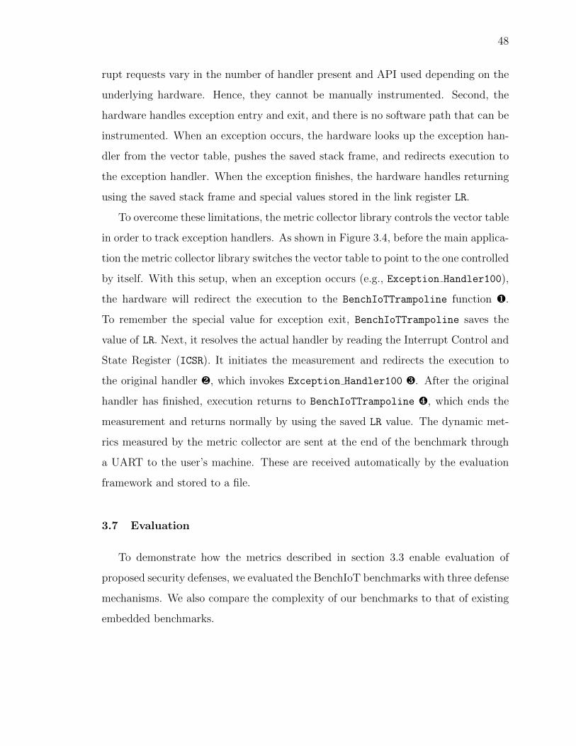
Fig. 3.4. Exception handlers tracking with BenchIoT.
50
3.7.1 Defense Mechanisms
The first defense is ARM’s Mbed-µVisor [105]. The µVisor is a hypervisor that en-
forces the principle of least privilege by running all application code in non-privileged
mode. Only µVisor’s code and parts of the OS run in privileged mode.
The second is a remote attestation mechanism drawn from well established at-
testation defenses [14, 106–108], and is purposed to authenticate the integrity of the
code residing on the device. The remote attestation mechanism uses a real-time task
that runs every 25ms in a separate thread to read the code in blocks, hash it, then
send the hashed block to the server to verify the code integrity. At initialization, the
remote attestation configures the MPU to save the code for reading and hashing the
application in a special region in flash that is only accessible in privileged mode.
The final defense mechanism is a data integrity mechanism we draw from [12,105,
109,110] that provides data integrity through memory isolation. Our implementation
moves sensitive data from RAM to a SECURE DATA REGION in Core Coupled RAM
(CCRAM) at compile time. CCRAM is an optional memory bank that is isolated
from RAM. It provides faster access to its data than RAM but has smaller size. The
secure data region is accessible in privileged mode only. It is enabled before accessing
the sensitive data and is disabled afterwards. The sensitive data depends on the
underlying benchmark (e.g., Flash IAP in firmware updater). It is important to note
that the goal of our security evaluation is to demonstrate how BenchIoT metrics
can help evaluate existing defense mechanisms with respect to security benefits and
performance overhead. It is not to propose new security mechanisms. The BenchIoT
benchmarks are built with the standard configuration of IoT-MCUS and popular
OSes to reflect real security challenges of current systems. For example, the baseline
is evaluated using the default configuration of Mbed-OS, which means the MPU is
not enabled and DEP is not supported.
We evaluated both the baseline and defense mechanisms on the STM32F479I-
Eval [38] board. Measurements were averaged over five runs for each benchmark.
51
Note that since Mbed-µVisor and remote attestation require an OS (i.e., remote
attestation requires a separate thread), it was only evaluated for the OS benchmarks.
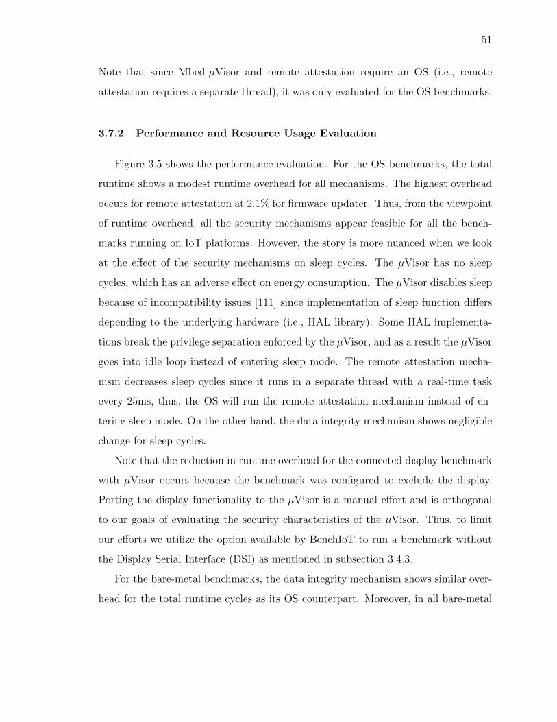
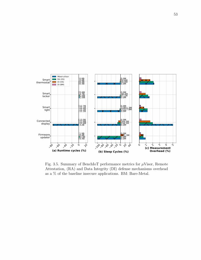
3.7.2 Performance and Resource Usage Evaluation
Figure 3.5 shows the performance evaluation. For the OS benchmarks, the total
runtime shows a modest runtime overhead for all mechanisms. The highest overhead
occurs for remote attestation at 2.1% for firmware updater. Thus, from the viewpoint
of runtime overhead, all the security mechanisms appear feasible for all the bench-
marks running on IoT platforms. However, the story is more nuanced when we look
at the effect of the security mechanisms on sleep cycles. The µVisor has no sleep
cycles, which has an adverse effect on energy consumption. The µVisor disables sleep
because of incompatibility issues [111] since implementation of sleep function differs
depending to the underlying hardware (i.e., HAL library). Some HAL implementa-
tions break the privilege separation enforced by the µVisor, and as a result the µVisor
goes into idle loop instead of entering sleep mode. The remote attestation mecha-
nism decreases sleep cycles since it runs in a separate thread with a real-time task
every 25ms, thus, the OS will run the remote attestation mechanism instead of en-
tering sleep mode. On the other hand, the data integrity mechanism shows negligible
change for sleep cycles.
Note that the reduction in runtime overhead for the connected display benchmark
with µVisor occurs because the benchmark was configured to exclude the display.
Porting the display functionality to the µVisor is a manual effort and is orthogonal
to our goals of evaluating the security characteristics of the µVisor. Thus, to limit
our efforts we utilize the option available by BenchIoT to run a benchmark without
the Display Serial Interface (DSI) as mentioned in subsection 3.4.3.
For the bare-metal benchmarks, the data integrity mechanism shows similar over-
head for the total runtime cycles as its OS counterpart. Moreover, in all bare-metal
52
benchmarks, there is no sleep cycles because it is lacking the sleep manager provided
by the Mbed-OS.
In order to collect the metrics in Figure 3.5 and all other dynamic results, the
evaluation framework used the metric collector runtime library. As shown in Fig-
ure 3.5(c), the metric collector library has a low average overhead of 1.2%.
Figure 3.6 shows a comparison of the memory usage overhead. The µVisor and
remote attestation mechanisms show an increase in memory usage overall. The remote
attestation shows a large increase heap and stack usage (over 200%) since it requires
an additional thread with a real-time task. However, it shows less than 30% increase
in RAM since the larger portion of of RAM usage is due to the global data and bss
regions. The µVisor requires additional global data and thus show a larger increase in
RAM. Both require additional code and thus increase Flash usage. The data integrity
mechanism for both the OS and bare-metal benchmarks change some local variables
to globals and moves them to CCRAM. Thus, they show negligible effect on memory
overall. Notice that data integrity mechanism is different between the bare-metal and
the OS benchmarks. The bare-metal benchmarks are consistently smaller than their
OS counterparts. As mentioned earlier in section 3.5, the bare-metal benchmarks
differ in their implementation although they provide the same functionality. These
differences are also manifested in the Flash metrics.
3.7.3 Security Evaluation
Minimizing privileged execution: Minimizing privileged execution is a desired
security property (subsection 3.3.1). However, as shown in Figure 3.7, the remote
attestation and data integrity mechanisms (for both OS and bare-metal) share the
risk of over-privileged execution that are present in the insecure baseline, since they
do not target minimizing privileged execution. Even with these defenses applied,
almost the entire application runs in privileged mode (e.g., 98.9% for Smart-light
using remote attestation in Figure 3.7(a)). The µVisor, however, shows the highest
53
80 60 40 20 0 20
(a) Runtime cycles (%)
Firmwareupdater
Connecteddisplay
Smartlight
Smartlocker
Smartthermostat
0.4B
3.2B
12.1B
2.8B
0.4B
0.4B
12.6B
12.1B
2.8B
0.4B
0.4B
12.6B
12.1B
2.7B
0.4B
1.9B
13.0B
12.7B
3.8B
0.8BMbed-uVisorRA (OS)DI (OS)DI (BM)
100 80 60 40 20 0 20 40
(b) Sleep Cycles (%)
0.0M
0.0M
0.0M
0.0M
0.0M
0.0M
234.1M
11517.9M
47.1M
50.0M
1.3M
244.5M
11851.3M
48.4M
50.6M
0.0M
0.0M
0.0M
0.0M
0.0M
0 1 2 3 4 5(c) Measurement Overhead (%)
Fig. 3.5. Summary of BenchIoT performance metrics for µVisor, RemoteAttestation, (RA) and Data Integrity (DI) defense mechanisms overheadas a % of the baseline insecure applications. BM: Bare-Metal.
54
40 30 20 10 0 10 20 30
(a) Flash (%)
Firmwareupdater
Connecteddisplay
Smartlight
Smartlocker
Smartthermostat
136.9KB
150.6KB
151.5KB
183.0KB
166.4KB
139.0KB
231.0KB
155.7KB
187.6KB
168.3KB
129.6KB
221.6KB
146.7KB
178.2KB
158.8KB
98.4KB
191.0KB
118.0KB
149.4KB
127.7KBMbed-uVisorRA (OS)DI (OS)DI (BM)
100 50 0 50 10
015
020
025
030
035
0
(b) Stack+Heap (%)
10.1KB
9.1KB
9.1KB
9.0KB
9.3KB
25.3KB
55.8KB
24.3KB
24.3KB
24.5KB
7.7KB
38.3KB
6.9KB
7.1KB
7.0KB
2.5KB
35.4KB
1.6KB
1.6KB
1.8KB
0 20 40 60 80 100
120
140
(c) RAM (%)
130.2KB
131.2KB
129.5KB
138.0KB
131.8KB
83.1KB
116.3KB
82.4KB
91.0KB
84.7KB
64.9KB
98.1KB
64.3KB
73.1KB
66.5KB
42.2KB
77.8KB
41.5KB
50.1KB
43.8KB
Fig. 3.6. Summary of BenchIoT memory utilization metrics for µVisor,Remote Attestation (RA), and Data Integrity (DI) defense mechanismsoverhead as a % over the baseline applications. The size in KB is shownabove each bar.
55
Table 3.3.Summary of BenchIoT memory isolation and control-flow hijacking met-rics for Mbed-µVisor, Remote Attestation (RA) and Data Integrity (DI)defense mechanisms overhead as a percentage of the baseline insecure ap-plications. BM: Bare-metal
reduction in privileged execution. For example, only 1.4% of Smart-light runs in
privileged mode. The Firmware-updater shows the lowest reduction for µVisor (i.e.,
55.4%) since it requires privileges to execute correctly (i.e., writing to Flash and
running the new firmware). However, the µVisor still reduces the total privilege cycles
by 44%. These improvements are expected since the µVisor runs all-application code
in non-privileged mode, except for the µVisor and OS code. The increase in SVC
cycles in all defenses is because they utilize system calls to execute their code. For
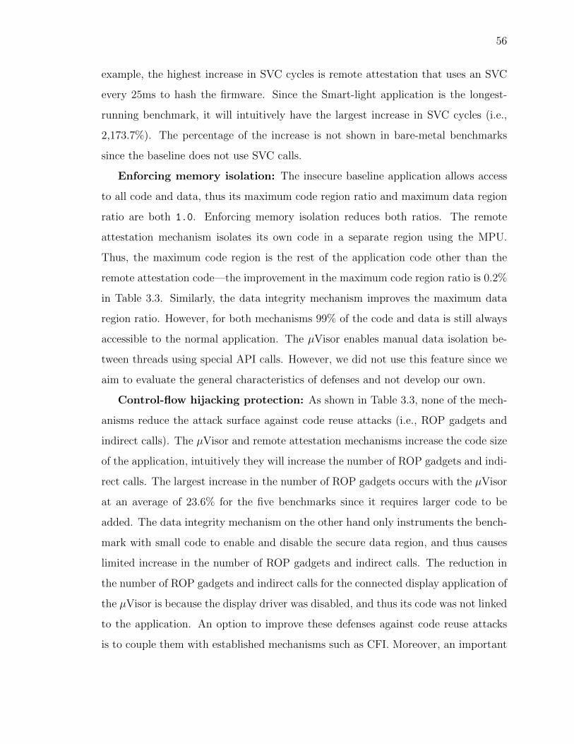
56
example, the highest increase in SVC cycles is remote attestation that uses an SVC
every 25ms to hash the firmware. Since the Smart-light application is the longest-
running benchmark, it will intuitively have the largest increase in SVC cycles (i.e.,
2,173.7%). The percentage of the increase is not shown in bare-metal benchmarks
since the baseline does not use SVC calls.
Enforcing memory isolation: The insecure baseline application allows access
to all code and data, thus its maximum code region ratio and maximum data region
ratio are both 1.0. Enforcing memory isolation reduces both ratios. The remote
attestation mechanism isolates its own code in a separate region using the MPU.
Thus, the maximum code region is the rest of the application code other than the
remote attestation code—the improvement in the maximum code region ratio is 0.2%
in Table 3.3. Similarly, the data integrity mechanism improves the maximum data
region ratio. However, for both mechanisms 99% of the code and data is still always
accessible to the normal application. The µVisor enables manual data isolation be-
tween threads using special API calls. However, we did not use this feature since we
aim to evaluate the general characteristics of defenses and not develop our own.
Control-flow hijacking protection: As shown in Table 3.3, none of the mech-
anisms reduce the attack surface against code reuse attacks (i.e., ROP gadgets and
indirect calls). The µVisor and remote attestation mechanisms increase the code size
of the application, intuitively they will increase the number of ROP gadgets and indi-
rect calls. The largest increase in the number of ROP gadgets occurs with the µVisor
at an average of 23.6% for the five benchmarks since it requires larger code to be
added. The data integrity mechanism on the other hand only instruments the bench-
mark with small code to enable and disable the secure data region, and thus causes
limited increase in the number of ROP gadgets and indirect calls. The reduction in
the number of ROP gadgets and indirect calls for the connected display application of
the µVisor is because the display driver was disabled, and thus its code was not linked
to the application. An option to improve these defenses against code reuse attacks
is to couple them with established mechanisms such as CFI. Moreover, an important
57
0 20 40 60 80 100
120
(a) Total privileged cycles (%)
Firmwareupdater
Connecteddisplay
Smartlight
Smartlocker
Smartthermostat
-44.0%
-98.6%
-98.6%
-98.3%
-97.6%
1.1%
0.1%
-0.5%
1.3%
-0.3%
-2.1%
0.5%
0.0%
0.5%
-0.5%
-0.0%
-0.8%
0.2%
1.2%
-0.0%
0 20 40 60 80 100
120
(b) Privileged thread cycles (%)
-44.7%
-100.0%
-100.0%
-100.0%
-100.0%
0.9%
-1.5%
-2.2%
-0.4%
-2.0%
-2.1%
0.4%
0.0%
0.5%
-0.5%
-0.0%
-0.8%
0.2%
1.3%
-0.0%
0 2 4 6 8 10(c) SVC cycles (%)
216.9%
35.2%
1307.3%
311.3%
115.9%
82.2%
185.3%
2173.7%
526.7%
183.2%
-1.0%
2.0%
-1.8%
-0.3%
2.2%
0.0%
0.0%
0.0%
0.0%
0.0%Mbed-uVisorRA (OS)DI (OS)DI (BM)
Fig. 3.7. Summary of BenchIoT comparison of minimizing privileged ex-ecution cycles for Mbed-µVisor, Remote Attestation (RA) and Data In-tegrity (DI) defense mechanisms as a % w.r.t the total runtime executioncycles. The overhead as a % of the baseline insecure applications is shownabove each bar. BM: Bare-Metal
aspect in defending against control-flow hijacking is enabling DEP. However, only the
remote attestation configures the MPU to enforce DEP. The µVisor does not enforce
DEP on heap. A similar observation was made by Clements et al. [9]. The data
integrity mechanism enables all access permissions to the background region (i.e., all
the memory space) then configures the MPU for various regions it is interested in.
However, regions that are not configured remain with the writable and executable
permissions, thus breaking DEP.
3.7.4 Energy Evaluation
Now we look at the energy implication of the benchmarks (Figure 3.8). While
all mechanisms showed similar runtime overhead, the energy consumption for the
58
µVisor mechanism increases significantly for the Smart-light benchmark. The Smart-
light benchmark spends large amounts of time in its sleep cycle, and since the µVisor
disables sleep cycles, the increase is pronounced in this application. Since the µVisor
disables sleep cycles, it consistently has an adverse effect on energy consumption for
all applications and this correlates to a drop in sleep cycles as shown in Figure 3.5.
Even if security mechanisms provide similar runtime overhead (e.g., data integrity
and µVisor for Smart-light), the difference in energy consumption can vary widely,
with an increase of 20% for µVisor. Such a conclusion cannot be obtained simply
from the metric of the total runtime overhead, but only when used in conjunction
with our metric of sleep cycles or energy consumed.
For the bare-metal benchmarks, the lack of an OS results in a lack of the sleep
manager, and thus the device keeps polling and drawing the same average power all
throughout. This can be noticed by the lack of sleep cycles in Figure 3.5 for the bare-
metal benchmarks. Thus, difference in energy consumption is caused by the increase
in total runtime due to the defense mechanism.
3.7.5 Code Complexity Comparison to BEEBS
To measure the complexity of BenchIoT benchmarks, we measure the cyclomatic
complexity [112] and compare to the BEEBS [23] benchmarks. BEEBS has been used
for security evaluation in embedded systems by EPOXY [8] and for energy evaluation
by many prior works [113–115]. We exclude HAL libraries from the measurements
for both benchmark suites as they differ based on the vendor and the hardware as
discussed in subsection 3.4.4. This provides a consistent comparison without the
influence of the underlying hardware.
Table 3.4 shows the comparison by computing the minimum, maximum, and me-
dian cyclomatic complexity and lines of code across all benchmarks. BenchIoT shows
much larger numbers—median complexity is higher by 162X (bare-metal) and 343X
(Mbed OS). The results are expected since BEEBS is designed to evaluate the energy
59
5 0 5 10 15 20 25 30(a) Power Overhead (%)
Firmwareupdater
Connecteddisplay
Smartlight
Smartlocker
Smartthermostat
0.171mW
0.178mW
0.173mW
0.153mW
0.163mW
0.167mW
0.163mW
0.144mW
0.153mW
0.163mW
0.169mW
0.164mW
0.143mW
0.155mW
0.162mW
0.184mW
0.174mW
0.185mW
0.171mW
0.174mW Mbed-uVisorRA (OS)DI (OS)DI (BM)
80 70 60 50 40 30 20 10 0 10 20 30 40 50
(b) Energy Overhead (%)
0.39mJ
3.21mJ
11.62mJ
2.35mJ
0.37mJ
0.38mJ
11.42mJ
9.69mJ
2.35mJ
0.37mJ
0.38mJ
11.5mJ
9.59mJ
2.34mJ
0.37mJ
1.96mJ
12.51mJ
12.99mJ
3.31mJ
0.8mJ
Fig. 3.8. Summary of power and energy consumption with the BenchIoTbenchmarks for the defense mechanisms as a % overhead of the baselineinsecure applications. Power and energy values are shown above each barin mW and mJ, respectively. BM: Bare-metal
60
Table 3.4.Comparison of code complexity between BenchIoT and BEEBS.
Benchmark SuiteCyclomatic Complexity Lines of Code
efficiency of the architecture, and not meant to provide stand-ins to real IoT applica-
tions. For example, BEEBS excludes peripherals and does not incorporate network
functionality.
3.8 Related Work
Numerous benchmarking suites have been proposed by the systems research com-
munity. However we focus our discussion on benchmarks targeting MCUS and IoT-
MCUS. Table 3.5 shows a comparison between BenchIoT and other benchmarks.
Desktop benchmarks: Soteria [118] is a static analysis system targeting IoT plat-
forms (e.g., Samsung’s SmartThings market), which are assumed to be connected to
the cloud. IoTAbench [119] and RIoTBench [120] are benchmarks for large-scale data
analysis of IoT applications. BenchIoT however targets IoT-MCUS.
High-end embedded systems benchmarks: Mibench [21] is a set of 35 general pur-
pose applications targeting embedded systems that are deigned to evaluate the per-
formance of the system. The benchmarks are user-space applications, with some of
the benchmarks assuming the presence of an OS and file system. ParMiBench [121]
is an extension of Mibench targeting multi-core embedded processors. Other bench-
marks target specific applications of embedded systems. MediaBench [122] targets
multimedia applications. DSP-stone [123] evaluates compilers for Digital Signal Pro-
cessing (DSP) applications for embedded systems. BenchIoT benchmarks differ from
61
Table 3.5.A Comparison of benchmarks and their categorization with respect to tasktype, networking communication, and peripherals between BenchIoT andother benchmarking suites.
BenchmarkTask Type Network
ConnectivityPeripherals
Sense Process Actuate
BEEBS [23] X
Dhrystone [22] X
CoreMark [82] X
IoTMark [116] X X partially (bluetooth only) only I2C
SecureMark [117] X
BenchIoT X X X X X
62
the above since we focus on IoT benchmarks, enabling security evaluations of IoT-
MCUS, and incorporating networking.
MCUS Benchmarks : The Worst-Case Execution Time (WCET) [124] evaluates
the worst execution time for real-time systems. Dhrystone [22] is a synthetic bench-
mark to evaluate integer performance. BEEBS [23] is a collection of benchmarks from
Mibench, WCET, DSP-stone, and the Livermore Fortran kernels [125] to evaluate en-
ergy consumption for bare-metal systems. CoreMark [82] targets evaluating processor
performance. However, all target a specific metric, do not utilize peripherals, and do
not show most of the characteristics of IoT applications. In contrast, BenchIoT is
aimed to enable security evaluation, it incorporates IoT application characteristics,
and covers both bare-metal and OS benchmarks.
IoT-MCUS benchmarks : IoTMark [116] evaluates the energy overhead of wireless
protocols such as Bluetooth. SecureMark [117] measures performance and energy for
implementing TLS on IoT edge nodes, it does not however demonstrate connectivity.
BenchIoT on the other hand demonstrates TCP/IP connectivity as well as security,
performance, memory, and energy evaluation.
3.9 Discussion
Extending BenchIoT: The flexible design of BenchIoT enables users to extend it
with their customized metrics or benchmarks. For example, a user interested in cycles
spent executing function foo can extend the global data structure of the metric col-
lector library, instrument foo with the BenchIoT API at the beginning and at the end
of foo, and add the metric to the result collection interface. Only 10 LoC are needed
for this customized metric. Moreover, users can evaluate their customized bench-
marks using the BenchIoT evaluation framework. The users customized benchmark
can use external peripherals (e.g., BLE) that were not included in core BenchIoT
benchmarks. We note that the reason for excluding external peripherals from the five
benchmarks is portability. For example, to add BLE users will need to buy an addi-
63
tional hardware module for BLE and use its non-portable software libraries. Thus,
external peripherals were excluded from the core benchmark suite. Since users can
easily add their own applications and evaluate them, we leave the choice of adding
external peripherals to the users. More details are available at [85].
Portability of BenchIoT: We believe BenchIoT can be extended to ARMv8-M, as
it shares many of the characteristics of ARMv7-M (i.e., include the TrustZone ex-
ecution). ARMv8-M however is a fairly new architecture, and a limited number of
boards are available at the time of writing. We leave this as future work. For other
architectures, the concepts of BenchIoT are applicable. However, since BenchIoT fol-
lows a software-based approach, the main task is porting the metric collector runtime
library, since it handles exception entry and exit. These are architecture dependent
(e.g., calling conventions, registers) and require architecture dependent implementa-
tion.
3.10 Conclusion
Benchmarks are pivotal for continued and accelerated innovation in the IoT do-
main. Benchmarks provide a common ground to evaluate and compare the different
security solutions. Alternatively, the lack of benchmarks burdens researchers with
measurements and leads to ad-hoc evaluations. For IoT-MCUS, the problem is exac-
erbated by the absence of commonly measured evaluation metrics, the tedious mea-
surement process, and the multi-dimensional metrics (performance, energy, security).
Concerned by the rising rate of attacks against IoT devices and the ad-hoc evalua-
tion of its defenses, we developed BenchIoT, a benchmarking suite and an evaluation
framework for IoT-MCUS to enable evaluating and comparing security solutions.
The suite is comprised of five representative benchmarks, that represent salient IoT
application characteristics: network connectivity, sense, compute, and actuate. The
applications run on bare-metal or a real-time embedded OS and are evaluated through
four types of metrics—security, performance,memory usage, and energy. We illustrate
64
how the evaluation metrics provide non-trivial insights, such as the differing effects
of different defenses on consumed energy, even though both show a similar runtime
overhead. BenchIoT benchmarks are open sourced freely available to the research
community [85].
65
4. µRAI: SECURING EMBEDDED SYSTEMS WITH
RETURN ADDRESS INTEGRITY
Embedded systems are deployed in security critical environments and have become
a prominent target for remote attacks. Microcontroller-based systems (MCUS) are
particularly vulnerable due to a combination of limited resources and low level pro-
gramming which leads to bugs. Since MCUS are often a part of larger systems,
vulnerabilities may jeopardize not just the security of the device itself but that of
other systems as well. For example, exploiting a WiFi System on Chip (SoC) allows
an attacker to hijack the smart phone’s application processor.
Control-flow hijacking targeting the backward edge, such as Return-Oriented Pro-
gramming (ROP) remains a threat for MCUS. Current defenses are either susceptible
to ROP-style attacks or require special hardware such as a Trusted Execution Envi-
ronment (TEE) that is not commonly available on MCUS.
We present µRAI 1, a compiler-based mitigation to prevent control-flow hijacking
attacks targeting backward edges by enforcing the Return Address Integrity (RAI)
property on MCUS. µRAI does not require any additional hardware such as TEE,
making it applicable to the wide majority of MCUS. To achieve this, µRAI intro-
duces a technique that moves return addresses from writable memory, to readable
and executable memory. It re-purposes a single general purpose register that is never
spilled, and uses it to resolve the correct return location. We evaluate against the
different control-flow hijacking attacks scenarios targeting return addresses (e.g., arbi-
trary write), and demonstrate how µRAI prevents them all. Moreover, our evaluation
shows that µRAI enforces its protection with negligible overhead.
1https://github.com/embedded-sec/uRAI
66
4.1 Introduction
Network connected embedded systems, which include the Internet of Things (IoT),
are used in healthcare, industrial IoT, Unmanned Aerial Vehicles (UAVs), and smart-
home systems [1]. Although these devices are used in security and privacy critical
applications, they are vulnerable to an increasing number of remote attacks. At-
tacks on these systems have caused some of the largest Distributed Denial-of-Service
(DDoS) attacks [2, 3], hijacked the control of UAVs [5, 6], and resulted in power grid
blackouts [26] among others.
A significant, yet particularly vulnerable portion of embedded devices are micro-
controller -based embedded systems (MCUS). MCUS run a single binary image either
as bare-metal (i.e., with no OS), or are coupled with a light-weight OS (e.g., Mbed-OS
or FreeRTOS [28, 29]). Existing solutions to protect MCUS [8, 9, 12–18, 46, 47, 126],
are still not deployed as they either require special hardware extensions, incur high
overhead, or have limited security guarantees. So far, deployed MCUS lack essential
protections that are available in their desktop counterparts [8, 9, 12], such as Data
Execution Prevention (DEP), stack canaries [7], and Address Space Layout Random-
ization (ASLR). More importantly, vulnerabilities of these systems are not confined
to the device itself, but can be a prominent attack vector to exploit a more powerful
system. For example, a WiFi System-on-Chip (SoC) can be used to compromise the
main application processor of a smart phone as shown by Google’s P0 [11]. These
attacks gain arbitrary code execution by hijacking the control-flow of the application.
Control-flow hijacking on MCUS and desktop systems originates from memory
safety or type safety violations that corrupt indirect control-flow transfers. This can
be through the forward edges (i.e., function pointers, and virtual table pointers) or
can be applied to protect forward edges as was done in desktop systems [61, 127].
These mechanisms reduce the attack surface of forward edges since the target set
of indirect calls for CFI is much smaller on MCUS (i.e., the highest is five in our
67
evaluation). In contrast, return addresses remain prime attack targets for adversaries
on MCUS. This is because return addresses are plentiful in any application, easier to
exploit, and more abundant than forward edges. When DEP is enforced, attackers
leverage Return-Oriented Programming (ROP) [90] to launch attacks. ROP is a code
reuse attack targeting backward edges, allowing an attacker to perform arbitrary
execution. ROP remains a viable attack vector even in presence of other defenses
such as stack canaries [7, 47], and randomization [8].
Protecting MCUS from control-flow hijacking attacks targeting backward edges,
imposes unique challenges compared to desktop systems. MCUS have constrained
resources (i.e., a few MBs Flash and hundreds of KBs RAM) and lack essential
features required to enforce standard desktop protections. For example, desktop
randomization-based defenses (e.g., ASLR) rely on the OS to randomize the location
of the stack and code layout for each run of the application . However, MCUS use
a single static binary image that is responsible for controlling the application logic,
configuring hardware (e.g., setting read, write, and execute permissions), and en-
forcing security mechanisms. This single binary image—containing the application,
all libraries, and a light-weight OS—is loaded once onto the device and has a single
address space. Changing the stack location for each run is not possible without re-
flashing the firmware to the device. Even then, the stack is located in RAM which
only has tens to hundreds of KBs of physical memory, as opposed to GBs of virtual
memory on a desktop system. Thus, an attacker can have at least approximate prior
knowledge of the device’s physical address space.
While researchers proposed several techniques to improve MCUS security, existing
techniques cannot prevent control-flow hijacking attacks on all backward edges unless
they incur prohibitive runtime overhead. Current defenses protect from control-flow
hijacking through randomization [8,46,47], memory isolation [9,12,46], or CFI [13,14].
However, these defenses only reduce the attack surface, but remain bypassable by
ROP style attacks [54, 65, 128–130]. For example, applying CFI for backward edges
limits the attacker’s ability to divert the control-flow to an over-approximated target
68
set, but is still vulnerable to control-flow bending style attacks [65]. An alternative
approach is to rely on information hiding. However, information hiding based de-
fenses [8, 46, 47] are vulnerable to information disclosure [54, 55] and profiling [77]
attacks. Ultimately, the security guarantees of information hiding remain limited
by the small amount of memory available on MCUS. For example, randomizing the
location of a safe-stack [8, 58] only results in a few bits of entropy. A safe stack pro-
tected through Software Fault Isolation (SFI) [56,57] removes the need for information
hiding, but will incur high overhead [60].
Defenses also limit their applicability by requiring special hardware extensions
that are not available for the wide majority of MCUS such as a Trusted Execution
Environment (TEE) [47]. In order to enforce stronger guarantees to protect return
addresses one option is to use a shadow stack [59, 60]. However, a shadow stack
requires hardware isolation to protect it from information disclosure [60, 131]. One
option is using the Memory Protection Unit (MPU), and thus require a system call
to access the protected shadow stack region at each function return [66]. The other
option is to rely on a TEE such as ARM’s TrustZone [13,24]. Both will result in high
overhead (e.g., 10–500% [13]). More importantly, TEEs are not commonly available
on MCUS [47]. The most common architecture currently and for the foreseeable
future is ARMv7-M, which does not provide a TEE. Moreover, ARMv7-M is still
actively used and deployed in new MCUS designs [132–136], requiring protections via
software updates [43, 44]. Without such protections, control-flow hijacking attacks
such as ROP remain a threat to the vast majority of MCUS.
In order to prevent ROP style attacks against many currently deployed MCUS, a
defense must enforce the Return Address Integrity (RAI) property without relying on
extra hardware (e.g., TEE) or incurring large overhead. The RAI property ensures
that return addresses are never writable except by an authorized instruction. All
control-flow hijacking attacks targeting backward edges require corrupting the return
address by overwriting it. Enforcing RAI eliminates all such attacks since return
addresses are never writeable by an attacker. This is different from existing defenses
69
such as CFI implementations [62], randomization, or stack canaries. These defenses
do not enforce RAI since return addresses remain writable. Such defenses only limit
the use of a corrupted return address, and thus remain vulnerable to ROP.
Enforcing the RAI property on MCUS without a TEE is challenging as return
addresses reside in writable memory (e.g., pushed to or popped from a stack). This
leads to three options to enforce RAI on MCUS and protect return addresses. The
first is enforcing SFI or allocating a protected privileged region of return addresses
(e.g., shadow stack [66]) for the entire execution of the application. However, this
requires isolating large parts of memory and results in high runtime overhead (i.e.,
5–25% [60, 66, 78]). If SFI is used within the application, it should be limited. An
alternative option is to keep return addresses in a reserved register that is never
spilled to memory or modified by unauthorized instructions. The reserved register
cannot be corrupted directly since it is not memory mapped. However, folding the
entire control-flow chain at runtime within a single register is challenging. The final
option is to remove the need for return addresses by inlining the entire code (i.e.,
since code is in R+X memory). However, this will lead to code size explosion and
require determining all execution paths statically.
Contribution: This chapter presents µRAI, a mechanism that prevents all control-
flow hijacking attacks targeting backward edges by enforcing the RAI property on
MCUS, with a low runtime overhead. µRAI only requires an MPU and the exclusive
use of a general purpose register, both of which are readily available on modern
MCUS. µRAI inserts a list of direct jumps in the code region of each function (i.e.,
in R+X memory), where each jump corresponds to a possible return target (i.e., a
call site) for the function. All functions have a finite set of call sites, and thus have
a finite set of possible return targets. By adding the set of possible return targets
for each function as direct jumps (i.e., in R+X memory, rather than writable stack
memory), a function can return by using the correct direct jump according to the
program execution.
70
SR = C
SR ⊕ key2
SR ⊕ key3
func2mainSR ⊕ key1
func1
SR = C ⊕ key1 SR = C ⊕ key1 ⊕ key2
SR = C ⊕ key1 ⊕ key3
SR is initialized to C
Functions read SR to resolve the correct
return location
Fig. 4.1. Illustration of encoding SR through an XOR chain. Arrows in-dicate a call site in the call graph. SR is XORed each time an edge iswalked.
The key to enforce the RAI property is to resolve the correct return target from
the appended list of direct jumps during runtime. At runtime, µRAI provides each
function a uniquely encoded ID (e.g., a hash value) each time the function is exe-
cuted. This ID value is unique and corresponds only to one of the possible return
targets. A function returns by reading the provided ID, and executing the direct
jump corresponding to the given ID. Intuitively, the unique ID µRAI provides must
also be protected by the RAI property (i.e., the ID is only readable), as an attacker
can modify the provided ID to divert the execution of the application. Moreover, it
must be encoded efficiently without incurring high runtime overhead.
µRAI provides each function with its ID by re-purposing and encoding a general
purpose register—hereafter known as the State Register (SR). As shown in Figure 4.1,
the SR is encoded through an XOR chain with hard-coded keys before each call and
XORed again with the same hard-coded key after returning from each call to restore
its previous value. SR is a dedicated register to µRAI only and is never spilled. By
our design an adversary can have full knowledge of what the used keys are, yet cannot
corrupt the SR.
Moreover, µRAI enforces the RAI property even within the execution context
of exception handlers (i.e., system calls and interrupts). Exception handlers exe-
cute in privileged mode, and can execute asynchronously (i.e., interrupts). As shown
71
: Regular function : Sensitive privileged data or MMIO
: Function called in exception handler context (privileged)
func5
func3func2
func4
func6 func7
func8
func1
MPU, VTOR
func5
func3func2
func4
func6 func7
func8
func1
MPU, VTOR
: SR encoding protection
: Exception handler SFI
(a) Default application. (b) μRAI application.
Corrupt return
address
Corrupt return address or sensitive MMIO/data
Un
pri
vileg
ed
Pri
vileg
ed
Fig. 4.2. Illustration µRAI’s protections. µRAI prevents exploiting a vul-nerable function (e.g., func8) to corrupt the return address or disable theMPU in privileged execution by coupling its SR encoding with exceptionhandler SFI.
72
Call Graph AnalyzerGenerates the
callers/callees for each function.
Instrumentation
LLVM: Compile Source
μRAI
2 3
4
5
EncoderGenerates function keys
and encodes thestate register.
μRAIBinary
1
LLVM IR
Source code
Fig. 4.3. An overview of µRAI’s workflow.
in Figure 4.2(a), enforcing the RAI property for a function called within an excep-
tion handler requires more than just protecting return addresses. For example, an
attacker can exploit an arbitrary write during an exception to disable the MPU, thus
eliminating any defense relying on the MPU (e.g., DEP). To overcome this limitation,
µRAI enforces SFI on sensitive privileged Memory Mapped I/O (MMIO) such as the
MPU, in addition to encoding SR as shown in Figure 4.2(b). Enforcing SFI within an
exception handler context only has negligible overhead since these are only a limited
portion of the entire application, unlike applying SFI for the entire application.
As shown in Figure 4.3, we implement µRAI as an LLVM extension that takes the
unprotected firmware and produces a hardened binary that enforces the RAI property.
While our prototype focuses on attacks targeting backward edges, we also couple our
implementation with a type-based CFI [79,137,138] to demonstrate its compatibility
with techniques protecting forward edges. µRAI can ensure its security guarantees
and reason about the complete state of application at compile time since it targets
MCUS that have a smaller code size compared to their desktop counter parts. We
evaluate µRAI on five representative MCUS applications and the CoreMark bench-
mark [82]. µRAI shows an average overhead of 0.1%. In summary, our contributions
are:
73
• Return Address Integrity property: We propose the RAI property as a
fundamental invariant to protect MCUS against control-flow hijacking attacks
targeting backward edges. The RAI property ensures absence of such attacks
without requiring special hardware extensions.
• Exception handler context protection: We enforce the RAI property even
for privileged and asynchronous executions of interrupts without special hard-
ware extension by coupling SFI with our SR encoding mechanism.
• µRAI: We design and implement a prototype that enforces the RAI property
on MCUS. We evaluate our implementation on CoreMark [82], representative
MCUS applications, and proof-of-concept attacks. Our results show that µRAI
enforces the RAI property with a runtime overhead of 0.1%.
4.2 Threat Model
We assume an attacker with arbitrary read and write primitives aiming to hijack
the control-flow (e.g., via ROP [90]) of the execution and gain control of the underlying
device. Unlike information hiding techniques, we also assume the attacker knows the
code layout. We target MCUS as our underlying system, which execute a single
statically linked binary image. We assume the application is compiled and loaded to
the underlying system safely, i.e., the application is buggy, but not malicious. We
do not assume the presence of any randomization-based techniques (e.g., ASLR) or
stack canaries, due to their shortcomings in our target class of devices as mentioned
above. We assume the device has an MPU enforcing DEP (i.e., Write ⊕ eXecute)
and supports two privilege levels of execution (i.e., privileged and unprivileged).
We complement our prototype with a type-based CFI [79, 137, 138] to protect
forward edges and show our technique is compatible with forward-edge defense mech-
anisms, however, our focus is on protecting backward-edges. The attacker’s aim is to
corrupt a backward-edge to divert control flow. We assume µRAI controls the entire
system (i.e., the application is compiled with µRAI). Since we protect against attacks
74
targeting code-pointers, attacks targeting non-control data such as Data-Oriented
Programming (DOP) are out of scope [89].
4.3 Background
MCUS use different architectures with different registers and calling conventions.
However, to understand the implementation of µRAI, we focus our discussion on our
target architecture, the ARMv7-M [40]. ARMv7-M is applied to Cortex-M (3,4,7)
processors, the most widely-deployed processor family for 32-bit MCUS [43,44].
Memory layout: As shown in Figure 4.4, ARMv7-M uses a single physical address
space for all code, data, and peripherals. It uses MMIO to access peripherals and
external devices. The memory model defines 4GB (32bit) physical address space,
however, devices are only equipped with a small portion of it. A high-end Cortex-
M4 [38] has only 2MB Flash for its code region, and only 320KB for RAM.
Memory Protection Unit: To enforce access controls (i.e., read, write, and execute)
on memory regions, ARMv7-M uses an MPU. Unlike the Memory Management Unit
(MMU) present in desktop systems, an MPU does not support virtual addressing,
but rather enforces permissions of physical address ranges. Moreover, MPUs only
support enforcing a limited number of regions (e.g., eight in ARMv7-M [40]).
Privilege modes: ARMv7-M supports two modes of execution: privileged and user
mode. Exception handlers (i.e., interrupts and system calls) are always executed in
privileged mode. User mode can execute in privileged mode by executing a Supervisor
call (SVC), the ARMv7-M system call. In both privileged and user (i.e., unprivileged)
mode, the accessible memory regions can be configured by the MPU. One exception
to the MPU configuration is the System Control Block (SCB), which is only accessible
in privileged mode and remains writable even if the MPU sets the permissions as read
only. The MPU and Vector Table offset Register (VTOR) both reside in the SCB,
and thus remain writable in privileged mode.
75
Code
(OS, Apps)0.5GB
SRAM
(Heap, Stack, etc)0.5GB
Peripherals
0.5GB
External RAM/ devices
2GB
PrivatePeripheral
Bus(MPU, VTOR, etc)
1MB
Vendorspecificmemory
511MB
0x00000000
0x20000000
0x40000000
0x60000000
0xE0000000
0xE0100000
Fig. 4.4. ARMv7-M memory layout.
Core registers: ARMv7-M provides 16 core registers. Registers R0–R12 are general
purpose registers. The remaining three registers are special purpose registers. Reg-
ister 13 is the Stack Pointer (SP). Register 14 is the Link Register (LR), and register
15 is the Program Counter (PC). LR is used to store the return address of functions
and exception handlers. If a function does not require pushing the return address to
the stack (i.e., has no callees), the program can use LR to return directly from the
function. This method is more efficient than pushing and popping the return address
from the stack. Since LR is initially reserved for return addresses by ARMv7-M, µRAI
uses it as its choice for the state register, SR.
Call instruction types: A call instruction in ARMv7-M has four possible types,
shown in Table 4.1. Both direct and indirect calls can automatically update LR to
hold the return address (i.e., the instruction following the call site) by using any of
the branch and link instructions in Table 4.1. Subsequent functions push LR on the
stack to store the return address in case they use another branch and link instruction
to call another function.
4.4 Design
µRAI enforces the RAI property by removing the need to spill return addresses
to the stack (i.e., writable memory). Instead, µRAI uses direct jump instructions
in the code region (i.e., R+X only memory) and the SR to determine the correct
76
Table 4.1.A summary of call instructions in ARMv7-M.
Description Instruction
Direct branch b <Label>
Direct branch and link bl <Label>
Indirect branch bx <Register>
Indirect branch and link blx <Register>
77
SR[Enc] = C
(Som
e in
itia
l val
ue)
Cal
led
by
som
e fu
nctio
n
Fu
nctio
n L
ooku
p T
able
(F
LT)
Fu
nct
ion
key
s (F
Ks
)
Address
<func1>:
...
...
...
SR[Enc] = SR[Enc]⊕
key1_1
...
call func2
func1_1
SR[Enc] = SR[Enc]⊕
key1_1
...
...
...
SR[Enc] = SR[Enc]⊕
key1_2
...
call func2
func1_2
SR[Enc] = SR[Enc]⊕
key1_2
...
...
FID
Return Target
CJump return_location1
ELSE
Jump ERROR
SR[Enc] =[
C ⊕
key1_1,# for func1_1
C ⊕
key1_2 # for func1_2
]
SR[Rec] > 0 # for func2_1
Address
<func2>:
...
...
...
SR[Rec]++
...
call func2
func2_1
SR[Rec]
...
IF SR[Rec] > 0
...
jump func2_1
...
Else
FID
Return Target
C ⊕ key1_1
Jump func1_1
C ⊕ key1_2
Jump func1_2
ELSE
Jump ERROR
1
2
4
5
3
6
7
Fig
.4.
5.Il
lust
rati
onofµ
RA
I’s
des
ign.Enc:
Enco
ded
SR
.Rec:
Rec
urs
ive
SR
.
78
return location. Both the direct jump instructions and the SR are not writable,
and therefore cannot be corrupted by an attacker. This protects against control-flow
hijacking attacks that corrupt return addresses (e.g., ROP [139,140]), even if the code
or its layout is completely disclosed to an adversary.
µRAI achieves this by modifying the program at the function level. Each function
will always have a finite set of possible return targets within the whole application.
Such a target set is obtained through analyzing the firmware’s call graph [141] stati-
cally. At runtime, a function can only have one unique correct return location from
the collected target set corresponding to a given call in the control flow. µRAI adds
a list of direct jumps to the possible return targets as part of the function itself at
compile time. At runtime, the unique return location from the list is resolved by
using the SR.
A key insight in designing µRAI is that no matter how large the list of pos-
sible return targets, µRAI still provides the same security guarantee. This is in
contrast to CFI mechanisms [62], where the security guarantees are reduced by over-
approximating the valid target set. There is no known method to statically compute
a fully precise target sets for CFI [62], while dynamic methods [64] require special
hardware extensions that are not available on MCUS. Thus, an attacker can perform
a control-flow bending style attack by over-writing the return address with a return
target within the over-approximated target set and divert the control-flow [65, 142].
Unlike CFI implementations, µRAI does not allow diverting the control-flow. For
µRAI, corrupting the control-flow requires either: (1) over-writing the direct jump
µRAI uses to return, which is not possible as the direct jump is in R+X memory; or
(2) corrupting the SR. This is again not possible as the SR is never spilled, but only
modified through XOR instructions using hard-coded values in R+X memory.
For µRAI, minimizing the possible return targets only affects the memory over-
head. µRAI encodes SR with a unique value for each possible return target. Each
function adds a direct jump corresponding to each unique value of the SR when the
function is entered as shown in Figure 4.5. Over-approximating the target set in-
79
creases the list direct jump instructions for the function. However, the direct jumps
from over-approximation are never executed since, during execution, the SR will never
be encoded with their corresponding values. In the following sections, we describe in
detail how the SR uniquely encodes each return target.
4.4.1 µRAI Terminology
Before discussing the details of µRAI’s design, we first define its main components,
which are illustrated in Figure 4.5.
Function Keys (FKs): These are hard-coded values to encode the value of the
SR at runtime. The SR is XORed with the key before the call to encode the call
location, and after the call to retrieve the previous value of the SR.
Function IDs (FIDs): These are the possible valid encoded values of the SR
when entering each function. Each FID value corresponds only to a single return
target in the application. A function cannot have two FIDs with the same value
corresponding to different return locations. The FID values depend on which FKs we
embed in the code (i.e., FID = SR ⊕ FK).
Function Lookup Table (FLT): FLT is the list of possible FIDs for the function
and their respective return targets.
Target Lookup Routine (TLR): TLR is the policy used to resolve the correct
return location. TLR must be designed with care to maintain negligible runtime
overhead.
4.4.2 Encoding The State Register
A central component in designing µRAI is the use of the SR to enforce the RAI
property. As shown in Figure 4.5, within each function, every FID in the FLT is
associated with a direct jump to a return target. At runtime, a function resolves the
correct return location by reading the value of the SR, and executing the direct jump
where FID = SR. At the beginning of the application, µRAI initializes the SR to a
80
known value (i.e., C at ¶). For the rest of the application, µRAI dynamically encodes
the SR according to two methods.
The first is with an XOR chain at each call site. Before the call site, the SR is
XORed with a hard-coded key (·) to provide each function a list of unique values of
the SR (i.e., FIDs), where each FID corresponds to a direct jump to the correct return
location (SR = C ⊕ key1 1 at ¸). To return from a function, the application reads
the current value of the SR and uses the direct jump associated with it (FID = C ⊕
key1 1 → Jump func1 1 at ¹). After returning, the SR is XORed again with the
same hard-coded key (º) to restore its previous value (i.e., C). The same process is
done for the following call sites, and the callee function can resolve the correct return
location by only reading the value or the SR. For example, if SR = C ⊕ key1 2 at ¹,
then func2 was called from the second call site. Thus, func1 2 is the correct return
location and µRAI executes the Jump func1 2 instruction.
The second use of the SR is a special case when handling recursive functions.
Recursive calls may cause a collision in the values of the SR (i.e., FIDs) inside the
recursive function. For example, func2 in Figure 4.5 is a recursive function. Assume
func2 is called from the first call site in func1 (i.e., SR = C ⊕ key1 1). Then, func2
calls itself twice at » (i.e., SR = C ⊕ key1 1 ⊕ any key ⊕ any key), the value of
the SR will be C ⊕ key1 1, thus colliding with the existing FID, and func2 is not able
to distinguish between the call at · and ». Thus, µRAI reserves some predetermined
bits in the SR that serve as a recursion counter. µRAI identifies recursive call sites,
and adjusts its instrumentation. Instead of an XOR instruction, µRAI increments
the recursion counter bits in the SR before the call (»). After the returning from the
call, µRAI decrements the recursion counter (¼). When the recursion counter reaches
zero, the recursive function can return normally using the FLT. Otherwise, it means
the function is still in a recursive call, and returns to itself to decrement the recursion
counter in the SR. We note that recursion is generally avoided in MCUS since they
have fixed memory, and should only occur with a known maximum bound [8, 66].
81
µRAI allows bits reserved for the recursion counter to be adaptable according to the
underlying application.
Using the SR as a single value however is prone to path-explosion and thus large
increases in the FLT. It also cannot handle corner cases for recursive calls (e.g.,
indirect recursion). µRAI resolves these issues by partitioning the SR.
4.4.3 SR Segmentation
To encode the SR, µRAI needs to determine the possible call sites (i.e., return
targets) of each function. Thus, the first step in µRAI’s workflow (i.e., Figure 4.3)
is to construct the firmware’s call graph [141]. µRAI uses the call graph to obtain
the possible return targets for each function in the FLT. As mentioned previously
in section 4.4, over-approximating the possible return targets because of imprecisions
in the call graph does not affect the security guarantees of µRAI.
The number of return targets for the function in the call graph provides a minimum
limit for the size of the function’s FLT. That is, if a function is called from three
locations, its FLT can be greater or equal to three, but never less than three. However,
the actual FLT (i.e., FIDs) can be larger than the actual possible call sites of a function
because of path-explosion. Consider the simple call graph in Figure 4.6(a), func3 is
called from two locations (i.e., func1 and func2). Ideally, func3 would have only
two possible values of the SR (i.e., FIDs), and thus an FLT size of two. However,
the FLT size is four in Figure 4.6(a), since it can be reached by multiple paths (i.e.,
two paths from main→func1 or two paths from main→func2). While this does not
affect the security guarantees of µRAI, it affects the memory overhead.
To generate efficient FLTs and minimize the effects of path-explosion, µRAI di-
vides the SR into multiple segments. As shown in Figure 4.6(b), the SR is divided
into two segments. Each function only uses its specified segment. All functions use
segment Enc1, while func3 uses Enc2. Thus, when either func1 or func2 call func3,
82
SR[E
nc]
SR[R
ec]
En
c2 =
0E
nc1
= C
0
(b)
Se
gme
nted
SR
(a)
SR
with
out
seg
men
tatio
n
SR[Enc] ⊕
FK3
SR[Enc] ⊕
FK4
func2
func3
main
func1
SR[Enc] ⊕
FK1
SR[Enc] ⊕
FK2
SR[Enc] ⊕
FK5
SR[Enc] ⊕
FK6
SR[E
nc]
SR[R
ec]
[C⊕
FK1⊕
FK5
,C⊕
FK2⊕
FK5
, C
⊕FK
3⊕
FK6
, C⊕
FK4⊕
FK6
]
0
SR[Enc1]⊕FK1
func3
main
func1
func2
SR[Enc1]⊕FK2
SR[Enc1]⊕FK3
SR[Enc1]⊕FK4
SR[Enc2]⊕FK5
SR[Enc2]⊕FK6
SR[R
ec]
SR[E
nc]
0[
C⊕
FK3
, C⊕
FK4]
0
SR[R
ec]
SR[E
nc]
0[
C⊕
FK1
, C⊕
FK2]
0SR[E
nc]
SR[R
ec]
[ C⊕
FK1,
C⊕
FK2
]0
SR[E
nc]
SR[R
ec]
[ C⊕
FK3,
C⊕
FK4
]0
SR[E
nc]
SR[R
ec]
C0
SR[R
ec]
SR[E
nc]
[FK
5, F
K6
]N
ot
use
d0
Fig
.4.
6.Il
lust
rati
onof
usi
ng
SR
segm
enta
tion
tore
duce
pat
hex
plo
sion
.Seg
men
tati
onre
duce
dth
ep
ossi
ble
SR
valu
esfo
rfunc3
by
hal
f.
83
Recursion Counter(s)(Higher N bits)
Encoded value(s)(Lower 32-N bits)
Segment 1 …. Segment K Segment M …. Segment 1
Fig. 4.7. Illustration segmenting the state register.
only the second segment (i.e., Enc2) is encoded. This reduces the size of func3’s FLT
to two, as opposed to four without segmentation.
Segmenting SR also enables µRAI to resolve the correct return location in case
of multiple recursive functions in a call path, as each function can use a segment
as a separate recursion counter. In addition, it allows handling other special cases
for recursion (e.g., functions with multiple recursive calls). As mentioned in subsec-
tion 4.4.2, recursion is rare in MCUS [8,66]. Since recursion is discouraged on MCUS,
we provide the details for handling special cases of recursion in Appendix A.
Figure 4.7 shows an overview of the SR. Each part can be divided to multiple
segments. µRAI automatically enables the number and size of segments to be adapt-
able depending on the underlying application. In the next sections, we will use the
encoded value for our discussion as it is the more general case in MCUS. The concepts
however cover both cases.
4.4.4 Call Graph Analysis and Encoding
µRAI performs several analyses on the call graph to: (1) calculate the number and
size of the SR segments; (2) generate the FKs for each call site to populate the FLTs
with its FIDs. To calculate the size and number of segments needed, µRAI uses a
pre-defined value of the maximum possible FLT size within an application—which we
refer to hereafter as FLTMax. This value can be set by the user or is a limit defined
by the underlying architecture. Since each segment in the SR can be equal to or lower
than FLTMax, µRAI divides the SR into equal segments each log2(FLTMax) bits.
84
To assign each function a segment in the SR, µRAI performs a Depth First Search
(DFS) of possible call paths for the application to calculate the FLT size for each
function without segmentation. When µRAI finishes the DFS analysis, it checks the
FLT size for each function. Functions with an FLT size < FLTMax are assigned to
the first segment of the SR. Other functions with FLT ≥ FLTMax are marked to use
the next segment, and DFS is repeated only on marked functions and their callees to
calculate their new FLT size when using the second segment. As shown in Figure 4.6,
segmentation reduces the size of the FLT in marked functions (i.e., 50% for func3’s
FLT). When the DFS analysis completes, the FLT size for each marked functions is
rechecked. Marked functions with an FLT size < FLTMax are assigned to the second
segment, and other functions are marked for the next iteration of DFS. The analysis
is repeated until all functions are assigned to a segment and each function has an
FLT size < FLTMax.
However, since the number of segments in the SR is ultimately limited, it is
possible that some call graphs will require more segments than is available in the SR.
Consider the call graph illustrated in Figure 4.8, both func10 and func11 require
additional segments in the SR, or an FLT with size > FLTMax. To overcome this
limitation, µRAI partitions the call graph. µRAI instruments calls to these functions
with an inlined system call to: (1) save the current SR to a privileged and isolated
region—which we call hereafter as the safe region; (2) reset the SR to its initial value.
The system call only occurs when calling into func10 and func11, however callees
of func10 and func11 do not require a system call, and are instrumented normally.
When returning to the prior partition, another system call restores the previous SR
to enable func7 and func8 to return correctly. Thus, µRAI can scale to any call
graph, regardless of path explosion. However, it is desirable to minimize such system
call transitions in order to maintain a low overhead.
Next, µRAI generates the FKs and populates the FLT for each function with its
FIDs. Each FID results from XORing the SR with an FK before the call site to
encode the SR. The FID values for each function must be unique (i.e., no collisions).
85
Therefore, FKs are chosen to avoid repeating FIDs within each function. However,
collisions are allowed across functions. For example, if key1 1 is chosen as zero
in Figure 4.5, func1 and func2 can have the same FID value of C (i.e., func2 will
have FIDs of C and C ⊕ key1 2). These FIDs correspond to different return targets
within each function.
To generate the FKs and FIDs efficiently, µRAI uses a modified Breadth First
Search (BFS). µRAI records the possible depths of each function in the call graph
(e.g., root functions have a depth of zero) from its previous DFS analysis. It traverses
each function in the call graph once by ordering functions according to their maximum
call depth. Starting from root functions (i.e., depth zero), µRAI generates the FKs
for each call site such that the result will not cause a collision. Once the FKs for all
functions in the current depth level are generated, µRAI generates the FKs for the
next level until all the FKs and FID are generated. Using our method is more efficient
than performing DFS again to generate the FKs and FIDs. Applying DFS to generate
the FKs and FIDs can cause large delays in compile time, since once a collision occurs,
DFS must be performed recursively starting from the violating call site to update all
its callees (i.e., until reaching the call graph’s leaves). However, using our modified
BFS, any collision is directly resolved between the caller and callee functions, without
the need for a costly updating process. Since applications on MCUS are smaller in
size, our analysis explores the possible states of the call graph.
4.4.5 Securing Exception Handlers and The Safe Region
An important aspect for defense mechanisms targeting MCUS is enabling protec-
tions for exception handlers. Interrupts execute asynchronously, making their protec-
tion more challenging than regular code. An interrupt can execute during any point
in the application, thus it is not possible to find a particular caller for an interrupt.
However, this makes interrupts, and exception handlers in general appear as root
functions in the call graph, since there is no exact call location in the call graph, but
86
rather they execute responding to an external event (e.g., a user pushing a button).
Consider Figure 4.8; root functions other than main are exception handlers.
At exception entry, µRAI saves the SR to the safe region, and resets the SR to
its initial value. Thus, at any time the exception handler executes, it will always
have the same SR value (i.e., the initial SR value). Callees of exceptions handlers are
then instrumented the same way regular functions are instrumented. At exception
exit, µRAI restores the saved SR value from the safe region so that code prior to the
exception executes correctly, and exits the exception context normally as defined by
the underlying architecture.
However, in order for µRAI to enforce the RAI property for exception handlers,
it needs to ensure the safe region is never corrupted within an exception handler.
The safe region resides in a privileged region, and thus cannot be corrupted in user
(i.e., unprivileged) mode. However, protecting the safe region during exception han-
dlers (i.e., privileged) requires additional measures since an arbitrary write within an
exception handler can access the safe region.
To protect the safe region, µRAI marks exception handler functions and any
function that can be called within an exception handler context. µRAI then masks
every store instruction in the marked functions to enforce SFI [56, 57] of the safe
region (e.g., clear most significant bit of the destination). This makes the safe region
only accessible at exception entry and exit, which are handled by µRAI. An attacker
cannot divert the control-flow to µRAI’s exception entry and exit instructions that
access the safe region since exception execution is protected by µRAI through the SR
and type-based CFI. As shown in Figure 4.8, functions called within an exception
handler amounts to only a limited portion of the functions in the application. This
is because interrupts must execute quickly and in fixed time, so that the application
can return to the normal execution prior to the interrupt for correct functionality.
Enforcing SFI for every store can degrade the performance. However, enforcing SFI of
the safe region for only functions called within an exception handler context, enables
87
func2
func3
func8
func5
func7
func4
func1
main
func11
Exception_handler1
Exception_handler2
func6
func14
func13func10
func9
: Regular function : Root function
: Function called in exception handler context
: Requires reseting the SR
Fig. 4.8. Conceptual illustration of µRAI’s call graph analysis.
an efficient implementation and limit the effect on the runtime overhead since many
of the instrumented functions execute for a limited portion of application.
4.4.6 Instrumentation
µRAI ensures the RAI property by instrumenting the application in six steps.
First, it instruments the call sites with an XOR instruction before the call instruction
to encode the SR, and after it to decode its previous value. In the case of recursion, it
increments the recursive counter before the call and decrements it afterwards. Second,
88
it reserves the SR so that other instructions previously using the SR will use a different
register. Third, it adds the FLT and TLR policy to resolve the correct return target
to each function. Fourth, it replaces any return instruction with the direct jumps
to the TLR. Fifth, it instruments exception handlers with µRAI’s entry and exit
routines. Finally, it instruments store instructions for functions callable in exception
handler context with masking instruction to protect the safe region. As discussed
in subsection 4.4.3, path-explosions affects the FLT size depending on the function
call sites and its depth in the call graph. Without carefully choosing suitable TLR
policy, the performance overhead of resolving the correct return location can become
prohibitive.
4.4.7 Target Lookup Routine Policy
Enforcing the RAI property is important, however, it is equally important to
maintain an acceptable performance overhead [30]. One simple TLR policy to resolve
the correct return location is to use a switch statement and compare the value of the
SR sequentially to the FID values in the FLT, and return once a match is found.
While this policy enforces the RAI property, it has unbounded, and possibly high
performance overhead for large FLTs.
An important aspect of µRAI is it ensures low, and deterministic overhead that is
independent of the FLT size. Therefore, µRAI uses a relative-jump policy to resolve
the correct return location using two instructions: (1) the first instruction in the TLR
is a relative jump (i.e., jump PC+SR); (2) a direct jump to the correct return location.
The relative-jump policy uses the SR as an index of a jump table, where the direct
jump pointing to the correct return location is at a distance equal to the SR (i.e.,
FID) from the first relative jump. Both instructions are impossible to modify by an
attacker since they reside in R+X memory. In addition, the attacker cannot modify
the SR in the first relative jump since it is never spilled. In case of SR segmentation,
only the specified segment is used for the first relative jump instruction.
89
Figure 4.9 illustrates an example of the relative-jump TLR. Consider func3 and
assume the PC points to the current location and each instruction size is 1—so that
PC+1 will lead to the next instruction. If SR = 3 at func3, then jump PC+SR will
jump to jump func2 1 which jumps to the correct return location (i.e., after the call
in func2). We can also conclude that the call path was main→ func2→ func3. For
func3, there is no FID = 2, and thus a jump ERROR was placed at index 2. This
is needed to ensure the correct return instructions are always at the correct distance
from the first relative jump. No matter how large the FLT size for a function is, the
performance overhead should be deterministic. However, to minimize the memory
overhead, it is better to have the SR as small as possible since the FLT size is equal
to the largest possible FID value (e.g., if we have SR=[1, 1024] we need to fill the
remaining 1022 with jump ERROR). Controlling the SR is done by minimizing the
values of the FKs. Thus, at each call site, µRAI chooses the FK that will minimize
the maximum FID value.
4.5 Implementation
µRAI is comprised of four components (see Figure 4.3). The first component
constructs the call graph of the application. The second component uses the call graph
to generate the encoding (i.e., FKs and FIDs) for each function. The third component
instruments the application with the generated FKs and FIDs. The fourth component
is a runtime library that secures saving the SR and restoring it from the safe region.
The call graph analysis and instrumentation are implemented as additional passes to
LLVM 7.0.1 [143]. The encoder is implemented as a Python script to leverage the
graph libraries [144]. We provide a Makefile package that automates the compilation
process of all four components. We implement µRAI to enforces the RAI property for
the ARMv7-M architecture, enabling it to protect a wide range of deployed MCUS.
As the Link Register (LR) in normally used to store return addresses, we use it as the
SR, and prohibit its use in any other operation.
90
SR[Enc] = 1
Address <func2>:… …… SR = SR ⊕2… call func3func2_1 SR = SR ⊕2… …… …… jump PC+SR … jump main_2
SR[Enc] = 1
Address <func1>:… …… SR = SR ⊕0… call func3func1_1 SR = SR ⊕0… …… …… jump PC+SR… jump main_1
Address <func3>:… …… …… …… jump PC+SR // ← PC value … jump func1_1 // FID = 1 … jump ERROR // No FID at 2… jump func2_1 // FID = 3 … …
SR[Enc] = [ 1, # func1_1 3, # func2_1 ]
Address <main>:… …… SR = SR ⊕1… call func1main_1 SR = SR ⊕1… …… SR = SR ⊕1… call func2main_2 SR = SR ⊕1… …
with special routines that moves the pushed values of PC and LR from the stack to
the safe region, as shown in Figure 4.14(b). It also moves the special value stored in
LR to the safe region. It then clears the locations of PC and LR from the exception
stack frame.
Since exception handlers are root functions in the call graph, the runtime library
sets LR to the initial value specified by the encoder. Functions are then instrumented
using the regular TLR and FLT instrumentation. When an exception handler exits,
µRAI restores the previously saved values of PC and LR from the safe region to their
location on the stack frame. It also sets LR to the special value required by the
hardware. Thus, enabling the exception to exit correctly.
This instrumentation enables correct execution, but alone fails to enforce the
RAI property. As exception handlers execute in privileged mode, an attacker can
corrupt the saved PC or LR in the safe region to force the exception exit to return
to a different location. Alternatively, an attacker can relocate the vector table by
overwriting the VTOR (see section 4.3). Finally, an attacker can disable the MPU
or alter its permissions to allow code injection. Simply setting VTOR and MPU as
99
read only is not effective and the MPU registers remain writable within exception
handlers. We verified this in our experiments.
To protect the above resources against these attacks, µRAI applies SFI only to
store instructions that can execute within exception handler context. The MPU reg-
isters are mapped within a contiguous address range (i.e., 16 bytes), while VTOR is
mapped separately. For the MPU and VTOR, we verify that the destination does not
point to within the MPU address range or VTOR. To protect the safe region, µRAI
places the safe region in a separate region. One option is to protect the safe region
the same way as the MPU. A more efficient approach is to leverage Core Coupled
RAM (CCRAM), which starts at a different address and is smaller than normal RAM
(e.g., 64KB compared to 320KB RAM in our board [38]). Placing the safe region in
CCRAM enables efficient protection through bit-masking the destination of store in-
structions to ensure it does not point to the safe region [56]. For our evaluation,
we leverage this more efficient bit-masking approach. See Figure 4.15 for a detailed
disassembly.
Our exception handler SFI routine can degrade performance if instrumented for
every store instruction in the application. However, we only instrument store instruc-
tions for functions that can be called within an exception handler context. These are
a small fraction of the entire application, and thus limits the effect of of the verifica-
tion routine. Furthermore, some exception handlers (i.e., SysTick, which increments
a fixed global) do not require the SFI instrumentation since the store performed is
always to a fixed address. Similarly, store instructions using SP for its destination are
not instrumented with SFI since instructions assigning SP use a bit-masking instruc-
tion to ensure it points to the stack region. Coupling the SR encoding with exception
handler SFI enforces the RAI property for exception handlers.
4.6 Evaluation
Our evaluation aims to answer the following questions:
100
1) Can µRAI fully prevent control-flow hijacking attacks targeting backward-edges?
2) What are the security benefits compared to CFI?
3) What is the performance overhead of µRAI?
4) What is the memory overhead of µRAI?
We evaluate the effectiveness of µRAI using five representative MCUS applications
(PinLock, FatFs-RAM, FatFs-uSD, LCD-uSD, and Animation) and the CoreMark
benchmark [82]. PinLock demonstrates a smart-lock receiving a user entered pin over
a serial port. The pin is hashed and compared against a precomputed (i.e., correct)
hash. If the comparison succeeds, the application sends an IO signal to mimic opening
the lock. Otherwise, the door remains locked. FatFs-uSD demonstrates a FAT file
system on an SD card, while FatFs-RAM mounts the file system in the device’s RAM.
Both applications perform similar functionality (i.e., accessing the FAT file system)
however their internals (e.g., Hardware Abstract Layer libraries) are different. LCD-
uSD reads multiple bitmap pictures from an SD card and displays them on the LCD
display. Animation demonstrates the animations effect on the LCD by displaying
multiple layers of bitmap images. All application are provided by STMicroelectronics
except PinLock, thus they represent realistic applications used for deployed MCUS.
CoreMark is a standardized benchmark developed by EEMBC [82] to measure MCUS
performance. The evaluation is performed using the STM32f479-EVAL [38] board and
includes the cost of type-CFI.
4.6.1 Security Analysis
In order to evaluate µRAI’s protections, we implement three control-flow hijack-
ing attacks on backward edges. The goal of these experiments is not to investigate
whether µRAI can protect from certain attack cases such as [146–148], but rather
to demonstrate µRAI’s ability to prevent any control-flow hijacking attack targeting
backward edges even in the presence of memory corruption vulnerabilities.
101
Control-flow hijacking attacks targeting backward edges must start from one of
three types of memory corruption vulnerabilities. First, a buffer overflow [149], where
an attacker leverages this vulnerability to overwrite the return address with the at-
tackers desired value. However, the attacker also corrupts all sequential memory
locations between the vulnerable buffer and the return address. Second, an arbi-
trary write (e.g., format string [150]), where the attacker directly over-writes the
return address, without needing to corrupt other memory locations. Third, a stack
pivot [151], where instead of over-writing the return address, the attacker controls the
stack pointer in this scenario. To launch the attack, the attacker sets the value of the
stack pointer to a buffer controlled by the attacker. Thus, when the application pops
the return address from the stack, it will pop the value from the attacker controlled
buffer.
Our experiments demonstrate the three types of attacks based on the PinLock
application. We assume these vulnerabilities exist in the application in the function
receiving the pin from the user, namely rx from uart. A successful attack uses the
underlying vulnerability to directly execute the unlock function to unlock the smart-
lock without entering the correct pin. As discussed in section 4.2, we assume the
attacker is aware of the entire code layout.
Buffer overflow: This attack assumes the return address is available in a sequentially
writable memory from the vulnerable buffer (e.g., on the stack). However, µRAI
uses R+X memory in Flash and an inaccessible SR. Both are not modifiable and the
attacker cannot modify the instructions that update the SR. The vulnerability here
only corrupts data available on the stack, but the return address is not affected. The
control flow is not diverted and µRAI successfully prevents the attack.
Arbitrary write: While the attacker is capable of writing to any available memory
for user code, such a vulnerability cannot be used to launch a successful attack.
The attacker cannot write directly to the SR (i.e., LR register) since it is not memory
mapped. Furthermore, the attacker cannot use µRAI’s return sequence in Figure 4.12
or Figure 4.13, as these only read the SR and never write to it. Modifying the
102
instructions is also not possible as the MPU configures them as only readable and
executable. A final option is to corrupt the saved PC or LR in the safe region from an
interrupt context entry in order to divert the return from the interrupt. When the
attack is attempted in unprivileged mode, it causes a fault since the safe region is
protected by the MPU. If the attack occurs during privileged execution, the safe region
is protected through our exception handler SFI mechanism. Thus, µRAI prevents the
attack.
Stack Pivot: Even when the attacker changes the stack pointer, this attack relies on
popping the return address from the stack. Since µRAI only uses the SR and the
instructions in Figure 4.12 or Figure 4.13, the attacker controlled buffer can corrupt
the function’s data, but is never used to return from the function. As a results, µRAI
successfully prevents control-flow hijacking through stack pivoting. Note that µRAI
does not prevent stack pivoting from occurring, but prevents using a stack pivot to
corrupt the return addresses.
4.6.2 Comparison to Backward-edge CFI
To understand the benefits of µRAI’s protections, we analyze the possible attack
surface compared to an alternative backward-edge CFI mechanism. With such a
mechanism, the function can return to only specific locations in the application.
These locations define the function’s target set. The target set is comprised of the set
of possible return sites for each function, enumerating the addresses of all instructions
immediately after a function call. For example, if function foo is called from three
different locations, the three instructions right after the return from the function call
are in the target set for foo. For indirect calls, we identify any call site matching the
function type signature of any indirect call within the current function to be a possible
call site [79,138,142]. We build our prototype on top of ACES’ [9] type-based CFI as
it provides a more precise target set than other existing work for MCUS. Intuitively,
the chance of a control-flow bending style attack [65] increases as the function target
103
Table 4.2.Analysis of the target set sizes for backward edge type-based CFI.
AppType-based CFI Target Set
Min. Median Max. Ave.
PinLock 1 2 8 3
FatFs uSD 1 6 94 21
FatFs RAM 1 5 94 27
LCD uSD 1 5 49 11
Animation 1 4 49 11
CoreMark 1 3 52 12
set size increases. That is, an attacker can still divert the control-flow to any location
within the target set.
Table 4.2 shows the minimum, median, maximum, and average target set sizes
for the functions within each application. Many applications share the same libraries
and Hardware Abstraction Layers (HALs). As these are called most frequently, the
worst case scenario for the applications (i.e., maximum target set size) can be shared
between applications sharing these libraries of HALs (e.g., FatFs-uSD and FatFs-
RAM). Averaged across all the applications in Table 4.2, a backward edge CFI will
have an average target set of 14 possible return locations. However, the effect of
imprecision on CFI are clearer when considering the maximum target set for each
application in Table 4.2. Averaged across all applications, an attacker will have a
target set of 58 possible return locations. In contrast to existing CFI implementation,
µRAI eliminates this remaining attack surface since it does not allow corrupting the
return address, rather than focusing on minimizing the target set, which is ultimately
limited to imprecisions [62].
4.6.3 Runtime Overhead
For defense mechanisms to be deployable, they must result in low performance
overhead [30]. This is highly relevant for MCUS, where they can have a real-time
104
PinLock
FatFs_uSD
FatFs_RAM
LCD_uSD
AnimationCoreMark
0.91.01.1
1.5
2.0
3.04.05.0
Norm
alize
d Ru
ntim
e
BaselineFull-SFIuRAI
Fig. 4.16. Comparison of runtime overhead for µRAI, Full-SFI, and base-line.
105
constraint as well. To evaluate the performance overhead, we modify the applications
to start the runtime measurement at the beginning of main and stop at the end of
the application. For PinLock, we stop the application after receiving 1000 pins that
alternate between incorrect pins, a correct pin, and a locking command that requests
the pin again. For CoreMark, we used its own performance reporting mechanism to
collect the measurement. The results are averaged across 20 runs.
Figure 4.16 compares the performance of the baseline, µRAI, and applying SFI
to all store instructions in the application—which we denote full-SFI. µRAI results
in an average overhead of 0.1%, with the highest overhead for CoreMark with 8.1%.
µRAI shows an improvement of 8.5% for FatFs RAM. This is not an inherent fea-
ture of µRAI but an effect of changing code layout and register usage (reserving
the LR register) in a hot loop in the application. Particularly, the baseline calls
aeabi memclr eight times to clear 64 bytes during each iteration. For µRAI, the
compiler optimized this to one call to clear 512 bytes at each iteration. To confirm
this, we evaluated an intermediate binary that uses the compiler changes without
applying any instrumentation. The optimization appeared and the intermediate bi-
nary showed an improvement of 14.4%. Compared to this intermediate binary, µRAI
has an overhead of 6.9%. Considering this effect µRAI yields an average overhead of
2.6%. In other applications, no improvement in runtime was observed between the
baseline and intermediate binaries. µRAI is efficient since it only adds three to five
cycles per call-return (see Table 4.3 for details). Return instructions are not a large
part of the application, thus µRAI yields a low overhead.
An alternative to µRAI is to apply a safe stack. Safe stack only prevents buffer
overflow attacks. To prevent other attack vectors (e.g., arbitrary write), a safe stack
must be coupled with SFI since information hiding offer limited guarantees on MCUS.
We use full-SFI to mimic protecting the safe stack by instrumenting all store instruc-
tions with a single bit-masking instruction except ones using SP (i.e., we assume SP
is verified at the point of assignment instead). The average overhead for full-SFI was
130.5%. In contrast to full-SFI, µRAI remains efficient since it limits SFI to functions
106
Table 4.3.Analysis of µRAI transformations and its effect on runtime overhead. N:Number of registers used in the instruction. P: Pipeline refill. P can bebetween 1–3 cycles.
InstructionBaseline µRAI
# of cycles Effect # of cycles
push {..,lr} 1 + N Remove lr N
pop {..,pc} 1 + N + P Remove pc N
eor Add 2 2
mov Add 2 2
add pc,<reg> Add 1 1 + P
b <label> Add 1 1 + P
Total 2 + 2 N + P 4 + 2 N + 2 P
µRAI Overhead 2 + P
Table 4.4.Summary of exception handler SFI protection for store instructions. %shows the percentage of statically protected instructions w.r.t the totalbaseline instructions.
App# of Store instruction
Static Total % Dynamic
PinLock 56 516 10.9 7
FatFs uSD 99 1,802 5.5 906K
FatFs RAM 7 1,116 0.6 7
LCD uSD 99 2,814 3.5 48K
Animation 99 2,760 3.6 66K
CoreMark 56 1,024 5.5 7
that can be called within an exception handler context, which are a small portion of
the application. Table 4.4 shows both the number of instrumented store instructions
both statically and dynamically. On average, µRAI statically instruments only 4.9%
of all store instructions in the baseline firmware.
107
4.6.4 FLT Encoding Analysis
A central component of µRAI is its encoder (see subsection 4.5.2) and how effi-
ciently it configures and populates the FLTs to reduce the effects of path explosion
on the memory overhead. As discussed in subsection 4.5.2, the encoder searches the
possible FLT sizes between FLTMin (i.e., the function with the highest number of
call sites in the application) and FLTMax (i.e., the highest possible FLT as defined by
the architecture) and chooses the configuration that will provide the lowest possible
memory overhead. Intuitively, the closer the encoder’s FLT is to FLTMin, the lower
the memory overhead is due to FLTs, since a larger FLT indicates FID collisions
in the FLT due to path explosion. Thus, to evaluate our encoder, we compare its
configured FLT size and SR segment size to the application FLTMin. Table 4.5 shows
FLTMin and µRAI’s configured FLT (i.e., FLTµRAI). µRAI’s FLT can only be at
powers of two since it partitions the SR’s bits into several segments, where each seg-
ment is log2(FLTµRAI) + 2. The additional two bits are because the size of each FID
in the FLT is a four byte branch instruction. µRAI consistently chooses the closest
power of two to FLTMin, and thus it is close to the best possible FLT configuration.
A key mechanism for µRAI’s encoder to achieve these results is partitioning the
SR into several segments where each function only uses a designated segment as
discussed in subsection 4.4.3. To demonstrate this effect, we show the FLT sizes
both with and without segmentation in Table 4.6. Averaged across all applications,
segmentation reduces FLT sizes by 78.1%. Intuitively, PinLock can be instrumented
without segmentation. As mentioned in subsection 4.5.3, many MCUS applications
use small code size and thus can be instrumented without segmentation. However, it
is segmented by µRAI since segmentation will result in lower memory overhead.
4.6.5 Encoder Efficiency Discussion
We further evaluate µRAI’s encoder and whether it populates the FLTs efficiently.
µRAI’s TLR requires the correct branch to be at a distance equal to the SR in FLT.
108
Table 4.5.Summary of µRAI’s Encoder FLT and SR segment configuration com-pared to FLTMin of each application.
Application FLTMin FLTµRAISR Segment
Size (bits)
PinLock 8 8 5
FatFs uSD 94 128 9
FatFs RAM 94 128 9
LCD uSD 49 64 8
Animation 49 64 8
CoreMark 52 64 8
109
Table 4.6.Summary of the segmentation effect on FLT size.
AppWithout Segmentation Segmented Ave.
ReductionMin. Max. Ave. Min. Max. Ave.
PinLock 1 12 3 1 8 2 33.3%
FatFs uSD 1 8,650 699 1 106 21 97.0%
FatFs RAM 1 632 86 1 105 20 76.7%
LCD uSD 1 11,898 727 1 59 12 98.3%
Animation 1 11,570 683 1 59 12 98.2%
CoreMark 1 352 23 1 52 8 65.2%
Thus, unused FIDs in the FLT are filled with JUMP ERROR to ensure the FLT is cor-
rectly aligned as was shown in Figure 4.9. Table 4.7 shows the FLT efficiency for each
application. We compute the FLT efficiency as the percentage of used FLT indices
over the total FLT size. If the FLT is sparse (i.e., a large number of FIDs are filled
with JUMP ERROR), then the efficiency is lower. Note that the encoder uses the infor-
mation extracted by the call graph analyzer (i.e., subsection 4.5.1). The call graph
analyzer is implemented as an LLVM IR pass. LLVM further optimizes the applica-
tion after this pass. Such optimization may remove call sites (e.g., due to inlining)
before µRAI instruments the firmware using its back-end pass (see subsection 4.5.3).
As a result, some portions of the encoder’s estimated FLT are unused. For example,
if the encoder estimated FLT contains a branch instruction to a function that has
been removed then this branch is ultimately replaced by a JUMP ERROR. This results
in lower efficiency in the final binary when compared to the encoder generated FLT
(e.g., 98.2% and 90.1% for average FLT efficiency in Animation). Averaged across
all the applications, the encoder and binary demonstrate a high FLT efficiencies as
98.3% and 93.8%, respectively.
110
Table 4.7.Summary of µRAI FLT Efficiency Evaluation.
AppEncoder Binary
Min. Max. Ave. Min. Max. Ave.
PinLock 100.0% 100.0% 100.0% 100.0% 100.0% 100.0%
FatFs uSD 83.3% 100.0% 97.1% 38.9% 100.0% 90.9%
FatFs RAM 83.3% 100.0% 97.6% 75.0% 100.0% 95.8%
LCD uSD 81.6% 100.0% 98.1% 44.4% 100.0% 94.0%
Animation 75.0% 100.0% 98.2% 22.2% 100.0% 90.1%
CoreMark 87.7% 100.0% 98.5% 43.9% 100.0% 92.0%
4.6.6 Scalability Analysis
µRAI scales its encoding scheme for larger applications by partitioning the call
graph whenever no satisfying keys are found as shown in Figure 4.8. This frees up
the SR to be reused, but results in some overhead since each transition between
partitions requires a system call. For our experiments, partitioning the call graph
was not needed. Table 4.8 shows the number of call sites in our evaluation, as well as
the number of nodes and edges handled by the encoder in the call graph. The number
of nodes does not equal the number of functions as many are optimized by inlining in
LLVM. In addition, the number of edges is different than the number of call sites as
a result of imprecisions in the call graph. Our evaluation uses applications compare
to and exceed the complexity of existing benchmarks (e.g., Animation compared to
CoreMark).
4.6.7 Memory Overhead
µRAI requires adding the instrumentation for encoding and decoding the SR at
each call site, adding the FLTs, instrumenting exception handler SFI, and using its
runtime library. In addition, we couple µRAI with a type-based CFI for forward
edges. This however increases the total utilized memory. Figure 4.17(a) shows the
111
Table 4.8.Summary of the number of call sites instrumented by µRAI, number ofnodes, and edges in the call graph for each application.
App# of Call sites
# of Nodes # of EdgesDirect Indirect
PinLock 26 0 22 26
FatFs uSD 111 97 37 473
FatFs RAM 29 94 25 373
LCD uSD 157 52 44 343
Animation 152 52 46 349
CoreMark 91 0 21 94
overhead of µRAI in RAM. For LCD-uSD and animation applications, µRAI incurs
negligible overhead. This is expected since the majority of µRAI’s instrumentation
utilizes Flash. Averaged across all applications, µRAI shows an increase of 15.2% for
RAM.
The Flash increase of µRAI’s instrumentation, exception handler SFI (EH-SFI),
and type-based CFI is shown in Figure 4.17(b). The majority of µRAI’s instrumen-
tation occurs in Flash, thus it is expected for µRAI to have a higher overhead for
Flash than for RAM. Averaged across all applications, µRAI shows an overhead of
34.6% for its instrumentation and FLT, and 9.5% for EH-SFI. Our type-based CFI
implementation shows an average increase of 10%. Combined, the average is 54.1%
for Flash. µRAI adds at most 22.4KB (i.e., Fats uSD). The increase is large for small
applications (e.g., PinLock), as any change can drastically affect their size. How-
ever, µRAI performs better for larger application (e.g., 22.7% for LCD uSD). That
is, µRAI overhead does not grow as the application size increases. We note that Flash
is available in larger sizes (i.e., MBs) than RAM (i.e., hundreds of KBs).
112
PinLock
FatFs_uSD
FatFs_RAMLCD_uSD
AnimationCoreMark
(a) RAM (KB)
0
10
20
30
40
50 BaselineuRAI
PinLock
FatFs_uSD
FatFs_RAMLCD_uSD
AnimationCoreMark
(b) Flash (KB)
0102030405060708090
100110
BaselineFLTuRAIInstrmnt.Type-CFIEH-SFI
Fig. 4.17. Illustration of µRAI’s memory overhead.
113
4.7 Related Work
Vast related work exists in the area of control-flow hijacking attacks and defenses.
However, not all are applicable to MCUS. Thus, our discussion focuses on related
work that targets MCUS or is applicable to it. We refer to the relevant surveys [30,
52,62,90,152–154] for readers interested in the general area of control-flow hijacking
attacks and defenses.
Remote attestation: Remote attestation use a challenge-response protocol to es-
tablish the authenticity and integrity of MCUS to a trusted server (i.e., verifier).
Remote attestation requires using a trust anchor on the prover (e.g., MCUS) to re-
spond the verifier’s challenge. C-FLAT [14] attests the integrity of the control-flow
by calculating a hash chain of the executed control-flow. LiteHAX [18] attests the
integrity of both the control-flow and the data-flow. DIAT enables on-device attesta-
tion by relying on security architectures that provide isolated trusted modules for the
program. Overall, remote attestation defenses require additional hardware (e.g., TEE
or additional processor). In addition, they only detect the occurrence of an attack.
µRAI prevents control-flow hijacking on backward edges without requiring hardware
extensions.
Memory isolation: Minion [12] enables partitioning the firmware into isolated
compartments on a per-thread-level, thus limiting a memory corruption vulnerabil-
ity to affect a single compartment and not the entire system. ACES [9] automates
compartmentalizing the firmware on a finer-grained intra-thread level. TyTan [16]
and TrustLite [17] enforce memory isolation through hardware extensions. Memory
isolation techniques can enable integrity and confidentiality between different com-
partments. However, they only confine the attack surface to a part of the firmware,
while µRAI focuses on preventing ROP style attacks against the entire firmware.
Information hiding: LR2 [45] uses SFI-based execute only memory (XoM) and
randomization to hide the location of code pointers. However, its implementation is
inefficient on MCUS as was shown by uXOM [46] which enables efficient implemen-
114
tation of XoM for Cortex-M processors. EPOXY [8] uses a modified and randomized
location of a SafeStack [58] to protect return addresses against buffer overflow style
attacks. µArmor protects from the same attack using stack canaries. Both EPOXY
and µArmor enforce essential defenses for MCUS efficiently and apply code random-
ization to hinder ROP attacks and produce different randomized binaries per device
to probabilistically mitigate scaling such attacks to a large number of devices. In
general, information hiding techniques remain bypassable and do not prevent attacks
with an arbitrary write primitive. µRAI however enforces the RAI property to prevent
ROP, and extends its protections to exception handlers.
CFI protections: SCFP [15] uses a hardware extension between the CPU’s fetch
and decode stage to enforce control-flow integrity and confidentiality of the firmware.
SCFP only mitigates attacks on backward edges (i.e., it does not prevent control-flow
bending style attacks [65]). CFI-CaRE [13] enforces CFI on forward-edges and a
hardware isolated shadow-stack to protect the backward edges. CFI-CaRE provides
strong protections against ROP style attacks, however, it requires using a TrustZone,
thus is not usable by a wide range of MCUS. RECFISH [66] applies CFI and a shadow
stack to MCUS binaries, without requiring source code. However, it places shadow
stack in a privileged region, thus requiring a system call to return from a function.
Thus, both CFI-CaRE and RECFISH incur a high overhead (e.g., 10-500% [13,66]).
µRAI enforces the RAI property without requiring a TEE and with a modest runtime
overhead.
4.8 Discussion
4.8.1 Imprecision and Irregular Control-Flow Transfers
µRAI handles imprecisions through separate encoding keys for each possible target
in the target set of its type-CFI. For example, if a target set contains {func1, func2}
and the indirect call is pointing to func1. Then µRAI will branch to the encoding
routine specific func1. If the target is a recursive function then a recursive encoding
115
is used. This ensures the function will always return to its exact caller and reduce the
effect of complexity since we find a satisfying key for each target individually instead
of the entire target set.
Our type-CFI implementation, although imprecise, has a maximum target set of
five functions for an indirect call on our evaluation. µRAI is evaluated on C. Using
C++ code results in two challenges. The first is larger target set for type-CFI, thus
larger FLT sizes. The second are attacks targeting the virtual table pointer such as
COOP style attacks [155]. These however are an orthogonal problem to stack safety
and may be protected through, e.g., OTI [156].
Supporting irregular control-flow transfers such as setjmp and longjmp requires
custom system calls. For setjmp, the system call stores the return location along
with the current SR value in the safe region. When executing longjmp, a system call
restores the return location and SR from the safe region. This mechanism also enables
the use of pre-compiled objects (e.g., newlib) since µRAI requires source code.
4.8.2 Miscellaneous
Protecting privileged user code: Protecting sensitive resources (e.g., MPU) require
the confinement of store instructions within a privileged execution of user code, where
the developer provides privileges for restricted operations for the given application.
Identifying these restricted operations automatically is non-trivial since they are ap-
plication specific as shown by previous work [8]. For our evaluation, these operation
occur during initialization. An attacker cannot divert the control-flow to these opera-
tions again (i.e., since µRAI enforces the RAI property and type-based CFI). However,
to enable flexible use of µRAI we enable developers to apply our SFI mechanism to
their privileged operations through annotation as was done by EPOXY [8].
edges and within exception handler contexts. To protect the forward edge, µRAI
116
leverages a state-of-the art forward edge type-based CFI mechanism. We acknowledge
the limitations of forward edge CFI.
Limiting the overhead of SFI: Interrupts are designed to be short and execute in
deterministic time on MCUS [157]. While µRAI efficiently restricts SFI to exception
handlers, SFI may still result in higher overhead in some cases. An alternative to SFI
is formal verification of exception handlers which we leave for future work.
Applicability to ARMv8-M and systems with an OS: We demonstrated µRAI on
bare-metal systems and ARMv7-M to show its applicability to most constrained sys-
tems. Since ARMv8-M is backward compatible, we believe µRAI is extensible to it.
Moreover, µRAI can utilize the TrustZone provided in ARMv8-M for its safe region.
Extending µRAI to systems with an OS requires modifying the context switch han-
dler to save and restore the SR per each thread. In addition, µRAI require restricting
the use of the register chosen as the SR. If such changes are made, µRAI can apply
its defenses to systems with a lightweight OS.
4.9 Conclusion
MCUS are increasingly deployed in security critical applications. Unfortunately,
even with proposed defenses, MCUS remain vulnerable against ROP style attacks.
We propose µRAI, a security mechanism able to prevent control-flow hijacking attacks
targeting backward edges by enforcing the RAI property on MCUS. µRAI does not re-
quire any special hardware extensions and is applicable to the majority of MCUS. We
apply µRAI on five realistic MCUS applications and show that µRAI incurs negligible
runtime overhead of 0.1%. We evaluate µRAI against various scenarios of control-
flow hijacking attacks targeting return addresses, and demonstrate its effectiveness in
preventing all such attacks.
117
5. CONCLUSION
Internet of Things systems are omnipresent, ranging smart home systems and smart
cities, to critical infrastructure such as industrial control systems. Although deployed
in security and safety critical domains, such systems lack basic mitigations against
control-flow hijacking attacks. As a result, IoT systems have become a prominent
target of remote attacks, causing some of the largest Distributed Denial-of-Service
attacks, and resulting in power grid blackouts.
To improve the security posture of IoT systems, we survey previous defense mit-
igations to secure IoT systems in Chapter 2. Building off our survery, We identify
two main issues in IoT systems security. First, efforts to protect IoT systems are
hindered by the lack of realistic benchmarks and evaluation frameworks. Second,
existing solutions to protect from control-flow hijacking on the return edge are either
impractical or have limited security guarantees.
This thesis address the first issue in Chapter 3. We present BenchIoT, a bench-
mark suite of five realistic IoT applications and an evaluation framework that enables
automated and extensible evaluation of 14 metrics covering security, performance,
memory usage, and energy. BenchIoT enables automated evaluation and comparison
of security mechanisms.
Chapter 4 introduces µRAI, a compiler mitigation enforce the Return Address
Integrity property. µRAI prevents all control-flow hijacking attacks on the return
edges with negligible runtime overhead. µRAI does not require special hardware
extensions and thus is practical and secure solution for IoT systems.
This thesis demonstrates that standardized benchmarks and metrics enable mea-
suring security properties on heterogeneous embedded IoT systems. Moreover, it
proves the effectiveness of customized static analysis and runtime monitors in prevent-
ing control-flow hijacking attacks on return edges at low runtime overhead. Combined,
118
this thesis advances the state-of-the-art of protecting IoT systems and benchmarking
its security.
REFERENCES
119
REFERENCES
[1] I. Analytics, “State of the IoT 2018: Number of IoT devicesnow at 7B Market accelerating,” 2018, https://iot-analytics.com/state-of-the-iot-update-q1-q2-2018-number-of-iot-devices-now-7b/.
[2] M. Antonakakis, T. April, M. Bailey, M. Bernhard, E. Bursztein, J. Cochran,Z. Durumeric, J. A. Halderman, L. Invernizzi, M. Kallitsis et al., “Understand-ing the mirai botnet,” in 26th {USENIX} Security Symposium ({USENIX}Security 17), 2017, pp. 1093–1110.
[3] S. Edwards and I. Profetis, “Hajime: Analysis of a decentralized internet wormfor iot devices,” Rapidity Networks, vol. 16, 2016.
[4] X. Li, X. Liang, R. Lu, X. Shen, X. Lin, and H. Zhu, “Securing smart grid: cyberattacks, countermeasures, and challenges,” IEEE Communications Magazine,vol. 50, no. 8, 2012.
[5] “Hijacking drones with a MAVLink exploit,” 2016, http://diydrones.com/profiles/blogs/hijacking-quadcopters-with-a-mavlink-exploit.
[6] D. Davidson, H. Wu, R. Jellinek, V. Singh, and T. Ristenpart, “Controllinguavs with sensor input spoofing attacks.” in WOOT, 2016.
[7] C. Cowan, C. Pu, D. Maier, J. Walpole, P. Bakke, S. Beattie, A. Grier, P. Wagle,Q. Zhang, and H. Hinton, “Stackguard: Automatic adaptive detection andprevention of buffer-overflow attacks.” in USENIX Security Symposium, vol. 98.San Antonio, TX, 1998, pp. 63–78.
[8] A. A. Clements, N. S. Almakhdhub, K. S. Saab, P. Srivastava, J. Koo, S. Bagchi,and M. Payer, “Protecting bare-metal embedded systems with privilege over-lays,” in Security and Privacy Symp. IEEE, 2017.
[9] A. A. Clements, N. S. Almakhdhub, S. Bagchi, and M. Payer, “Aces: Automaticcompartments for embedded systems,” in 27th USENIX Security Symposium(USENIX Security 18). USENIX Association, 2018.
[10] N. S. Almakhdhub, A. A. Clements, M. Payer, and S. Bagchi, “Benchiot: Asecurity benchmark for the internet of things,” in 2019 49th Annual IEEE/IFIPInternational Conference on Dependable Systems and Networks (DSN). IEEE,2019, pp. 234–246.
[11] G. Beniamini, “Project Zero: Over The Air: Exploiting Broad-coms Wi-Fi Stack,” 2017, https://googleprojectzero.blogspot.com/2017/04/over-air-exploiting-broadcoms-wi-fi 4.html, 2017.
[12] C. H. Kim, T. Kim, H. Choi, Z. Gu, B. Lee, X. Zhang, and D. Xu, “Securingreal-time microcontroller systems through customized memory view switching,”in Network and Distributed Systems Security Symp.(NDSS), 2018.
[13] T. Nyman, J.-E. Ekberg, L. Davi, and N. Asokan, “Cfi care: Hardware-supported call and return enforcement for commercial microcontrollers,” inInternational Symposium on Research in Attacks, Intrusions, and Defenses.Springer, 2017, pp. 259–284.
[14] T. Abera, N. Asokan, L. Davi, J.-E. Ekberg, T. Nyman, A. Paverd, A.-R.Sadeghi, and G. Tsudik, “C-flat: control-flow attestation for embedded systemssoftware,” in Proceedings of the 2016 ACM SIGSAC Conference on Computerand Communications Security. ACM, 2016, pp. 743–754.
[15] M. Werner, T. Unterluggauer, D. Schaffenrath, and S. Mangard, “Sponge-basedcontrol-flow protection for iot devices,” arXiv preprint arXiv:1802.06691, 2018.
[16] F. Brasser, B. El Mahjoub, A.-R. Sadeghi, C. Wachsmann, and P. Koeberl,“Tytan: tiny trust anchor for tiny devices,” in Design Automation Conference(DAC), 2015 52nd ACM/EDAC/IEEE. IEEE, 2015, pp. 1–6.
[17] P. Koeberl, S. Schulz, A.-R. Sadeghi, and V. Varadharajan, “Trustlite: A se-curity architecture for tiny embedded devices,” in Proceedings of the NinthEuropean Conference on Computer Systems. ACM, 2014, p. 10.
[18] G. Dessouky, T. Abera, A. Ibrahim, and A.-R. Sadeghi, “Litehax: lightweighthardware-assisted attestation of program execution,” in Proceedings of the In-ternational Conference on Computer-Aided Design. ACM, 2018, p. 106.
[19] J. L. Henning, “Spec cpu2006 benchmark descriptions,” ACM SIGARCH Com-puter Architecture News, vol. 34, no. 4, pp. 1–17, 2006.
[20] M. Larabel and M. Tippett, “Phoronix test suite,” Phoronix Media,[Online].Available: http://www. phoronix-test-suite. com/.[Accessed June 2016], 2011.
[21] M. R. Guthaus, J. S. Ringenberg, D. Ernst, T. M. Austin, T. Mudge, and R. B.Brown, “Mibench: A free, commercially representative embedded benchmarksuite,” in Workload Characterization, 2001. WWC-4. 2001 IEEE InternationalWorkshop on. IEEE, 2001, pp. 3–14.
[22] R. P. Weicker, “Dhrystone: a synthetic systems programming benchmark,”Communications of the ACM, vol. 27, no. 10, pp. 1013–1030, 1984.
[23] J. Pallister, S. J. Hollis, and J. Bennett, “BEEBS: open benchmarks forenergy measurements on embedded platforms,” CoRR, vol. abs/1308.5174,2013. [Online]. Available: http://arxiv.org/abs/1308.5174
[24] ARM, “Trustzone for cortex-m,” https://www.arm.com/why-arm/technologies/trustzone-for-cortex-m, 2019.
[25] N. S. Almakhdhub, A. A. Clements, S. Bagchi, and M. Payer, “µRAI: Securingembedded systems with return address integrity,” in Proc. of ISOC Network &Distributed System Security Symposium (NDSS). https://hexhive. epfl. ch/pub-lications/files/20NDSS. pdf, 2020.
[26] A. Cherepanov, “WIN32/INDUSTROYER: A new threat for industrial controlsystems,” 2017, https://www.welivesecurity.com/wp-content/uploads/2017/06/Win32 Industroyer.pdf.
[27] K. S. Lab, “Car hacking research: Remote attacktesla motors,” https://keenlab.tencent.com/en/2016/09/19/Keen-Security-Lab-of-Tencent-Car-Hacking-Research-Remote-Attack-to-Tesla-Cars,2016.
[30] L. Szekeres, M. Payer, T. Wei, and D. Song, “Sok: Eternal war in memory,” inSecurity and Privacy (SP), 2013 IEEE Symposium on. IEEE, 2013, pp. 48–62.
[31] Y. Li, J. M. McCune, and A. Perrig, “Viper: verifying the integrity of periph-erals’ firmware,” in Proceedings of the 18th ACM conference on Computer andcommunications security, 2011, pp. 3–16.
[32] I. D. O. Nunes, K. Eldefrawy, N. Rattanavipanon, M. Steiner, and G. Tsudik,“{VRASED}: A verified hardware/software co-design for remote attestation,”in 28th {USENIX} Security Symposium ({USENIX} Security 19), 2019, pp.1429–1446.
[33] N. Asokan, F. Brasser, A. Ibrahim, A.-R. Sadeghi, M. Schunter, G. Tsudik,and C. Wachsmann, “Seda: Scalable embedded device attestation,” in Proceed-ings of the 22nd ACM SIGSAC Conference on Computer and CommunicationsSecurity, 2015, pp. 964–975.
[34] A. Ibrahim, A.-R. Sadeghi, G. Tsudik, and S. Zeitouni, “Darpa: Device attes-tation resilient to physical attacks,” in Proceedings of the 9th ACM Conferenceon Security & Privacy in Wireless and Mobile Networks, 2016, pp. 171–182.
[37] “Kernel source tree for Raspberry Pi Foundation,” https://github.com/raspberrypi/linux/blob/e2d2941326922b63d722ebc46520c3a2287b675f/Documentation/features/vm/ELF-ASLR/arch-support.txt, 2020.
[43] R. York, “ARM Embedded segment market update,” 2015, https://www.arm.com/zh/files/event/1 2015 ARM Embedded Seminar Richard York.pdf.
[44] E. Sourcing, “Reversal of fortune for chip buyers: average prices for micro-controllers will rise,” 2017, http://www.electronics-sourcing.com/2017/05/09/reversal-fortune-chip-buyers-average-prices-microcontrollers-will-rise/.
[45] K. Braden, L. Davi, C. Liebchen, A.-R. Sadeghi, S. Crane, M. Franz, andP. Larsen, “Leakage-resilient layout randomization for mobile devices.” inNDSS, 2016.
[46] D. Kwon, J. Shin, G. Kim, B. Lee, Y. Cho, and Y. Paek, “uxom:Efficient execute-only memory on ARM cortex-m,” in 28th USENIX SecuritySymposium (USENIX Security 19). Santa Clara, CA: USENIX Association,Aug. 2019, pp. 231–247. [Online]. Available: https://www.usenix.org/conference/usenixsecurity19/presentation/kwon
[47] A. Abbasi, J. Wetzels, T. Holz, and S. Etalle, “Challenges in designing exploitmitigations for deeply embedded systems,” in 2019 IEEE European Symposiumon Security and Privacy (EuroS P), June 2019, pp. 31–46.
[48] C. Kil, E. C. Sezer, A. M. Azab, P. Ning, and X. Zhang, “Remote attestationto dynamic system properties: Towards providing complete system integrityevidence,” in 2009 IEEE/IFIP International Conference on Dependable Systems& Networks. IEEE, 2009, pp. 115–124.
[49] G. Dessouky, S. Zeitouni, T. Nyman, A. Paverd, L. Davi, P. Koeberl, N. Asokan,and A.-R. Sadeghi, “Lo-fat: Low-overhead control flow attestation in hard-ware,” in Proceedings of the 54th Annual Design Automation Conference 2017,2017, pp. 1–6.
[50] S. Zeitouni, G. Dessouky, O. Arias, D. Sullivan, A. Ibrahim, Y. Jin, and A.-R. Sadeghi, “Atrium: Runtime attestation resilient under memory attacks,”in 2017 IEEE/ACM International Conference on Computer-Aided Design (IC-CAD). IEEE, 2017, pp. 384–391.
[51] T. Abera, R. Bahmani, F. Brasser, A. Ibrahim, A.-R. Sadeghi, and M. Schunter,“Diat: Data integrity attestation for resilient collaboration of autonomous sys-tems,” in Network and Distributed Systems Security Symp.(NDSS), 2019.
[52] P. Larsen, A. Homescu, S. Brunthaler, and M. Franz, “Sok: Automated softwarediversity,” in 2014 IEEE Symposium on Security and Privacy. IEEE, 2014,pp. 276–291.
[53] A. Cui and S. J. Stolfo, “Defending embedded systems with software sym-biotes,” in International Workshop on Recent Advances in Intrusion Detection.Springer, 2011, pp. 358–377.
[54] A. Oikonomopoulos, E. Athanasopoulos, H. Bos, and C. Giuffrida, “Pok-ing holes in information hiding,” in 25th {USENIX} Security Symposium({USENIX} Security 16), 2016, pp. 121–138.
[55] E. Goktas, B. Kollenda, P. Koppe, E. Bosman, G. Portokalidis, T. Holz, H. Bos,and C. Giuffrida, “Position-independent code reuse: On the effectiveness of aslrin the absence of information disclosure,” in 2018 IEEE European Symposiumon Security and Privacy (EuroS&P). IEEE, 2018, pp. 227–242.
[56] R. Wahbe, S. Lucco, T. E. Anderson, and S. L. Graham, “Efficient software-based fault isolation,” in ACM SIGOPS Operating Systems Review, vol. 27,no. 5. ACM, 1994, pp. 203–216.
[57] B. Yee, D. Sehr, G. Dardyk, J. B. Chen, R. Muth, T. Ormandy, S. Okasaka,N. Narula, and N. Fullagar, “Native client: A sandbox for portable, untrustedx86 native code,” in 2009 30th IEEE Symposium on Security and Privacy.IEEE, 2009, pp. 79–93.
[58] V. Kuznetsov, L. Szekeres, M. Payer, G. Candea, R. Sekar, and D. Song, “Code-pointer integrity,” in 11th {USENIX} Symposium on Operating Systems Designand Implementation ({OSDI} 14), 2014, pp. 147–163.
[59] T. H. Dang, P. Maniatis, and D. Wagner, “The performance cost of shadowstacks and stack canaries,” in Proceedings of the 10th ACM Symposium onInformation, Computer and Communications Security. ACM, 2015, pp. 555–566.
[60] N. Burow, X. Zhang, and M. Payer, “Shining light on shadow stacks,” in IEEESecurity and Privacy Symp. IEEE, 2019.
[61] M. Abadi, M. Budiu, U. Erlingsson, and J. Ligatti, “Control-flow integrity prin-ciples, implementations, and applications,” ACM Transactions on Informationand System Security (TISSEC), vol. 13, no. 1, p. 4, 2009.
[62] N. Burow, S. A. Carr, J. Nash, P. Larsen, M. Franz, S. Brunthaler, andM. Payer, “Control-flow integrity: Precision, security, and performance,” ACMComputing Surveys (CSUR), vol. 50, no. 1, p. 16, 2017.
[63] G. Ramalingam, “The undecidability of aliasing,” ACM Transactions on Pro-gramming Languages and Systems (TOPLAS), vol. 16, no. 5, pp. 1467–1471,1994.
[64] H. Hu, C. Qian, C. Yagemann, S. P. H. Chung, W. R. Harris, T. Kim, andW. Lee, “Enforcing unique code target property for control-flow integrity,” inProceedings of the 2018 ACM SIGSAC Conference on Computer and Commu-nications Security. ACM, 2018, pp. 1470–1486.
[65] N. Carlini, A. Barresi, M. Payer, D. Wagner, and T. R. Gross, “Control-flowbending: On the effectiveness of control-flow integrity,” in 24th {USENIX}Security Symposium ({USENIX} Security 15), 2015, pp. 161–176.
[66] R. J. Walls, N. F. Brown, T. Le Baron, C. A. Shue, H. Okhravi, and B. C. Ward,“Control-flow integrity for real-time embedded systems,” in 31st EuromicroConference on Real-Time Systems (ECRTS 2019). Schloss Dagstuhl-Leibniz-Zentrum fuer Informatik, 2019.
124
[67] P. Akritidis, C. Cadar, C. Raiciu, M. Costa, and M. Castro, “Preventing mem-ory error exploits with wit,” in 2008 IEEE Symposium on Security and Privacy(sp 2008). IEEE, 2008, pp. 263–277.
[68] S. Nagarakatte, J. Zhao, M. M. Martin, and S. Zdancewic, “Softbound: Highlycompatible and complete spatial memory safety for c,” in Proceedings of the30th ACM SIGPLAN Conference on Programming Language Design and Im-plementation, 2009, pp. 245–258.
[69] P. Akritidis, M. Costa, M. Castro, and S. Hand, “Baggy bounds checking: Anefficient and backwards-compatible defense against out-of-bounds errors.” inUSENIX Security Symposium, 2009, pp. 51–66.
[70] Z. Liu and J. Criswell, “Flexible and efficient memory object metadata,” ACMSigplan Notices, vol. 52, no. 9, pp. 36–46, 2017.
[71] K. Serebryany, D. Bruening, A. Potapenko, and D. Vyukov, “Addresssanitizer:A fast address sanity checker,” in Presented as part of the 2012 {USENIX}Annual Technical Conference ({USENIX}{ATC} 12), 2012, pp. 309–318.
[72] N. Burow, D. McKee, S. A. Carr, and M. Payer, “Cup: Comprehensive user-space protection for c/c++,” in Proceedings of the 2018 on Asia Conference onComputer and Communications Security, 2018, pp. 381–392.
[73] D. Midi, M. Payer, and E. Bertino, “Memory safety for embedded devices withnescheck,” in Proceedings of the 2017 ACM on Asia Conference on Computerand Communications Security. ACM, 2017, pp. 127–139.
[74] P. Levis, S. Madden, J. Polastre, R. Szewczyk, K. Whitehouse, A. Woo, D. Gay,J. Hill, M. Welsh, E. Brewer et al., “Tinyos: An operating system for sensornetworks,” in Ambient intelligence. Springer, 2005, pp. 115–148.
[76] M. Bishop, M. Dilger et al., “Checking for race conditions in file accesses,”Computing systems, vol. 2, no. 2, pp. 131–152, 1996.
[77] R. Rudd, R. Skowyra, D. Bigelow, V. Dedhia, T. Hobson, S. Crane, C. Liebchen,P. Larsen, L. Davi, M. Franz et al., “Address oblivious code reuse: On theeffectiveness of leakage resilient diversity.” in NDSS, 2017.
[78] D. Sehr, R. Muth, C. L. Biffle, V. Khimenko, E. Pasko, B. Yee, K. Schimpf, andB. Chen, “Adapting software fault isolation to contemporary cpu architectures,”in Usenix Security Symposium, 2010.
[80] K. Lu and H. Hu, “Where does it go? refining indirect-call targets with multi-layer type analysis,” in Proceedings of the 2019 ACM SIGSAC Conference onComputer and Communications Security, 2019, pp. 1867–1881.
[81] J. L. Henning, “Spec cpu2006 memory footprint,” SIGARCH Comput.Archit. News, vol. 35, no. 1, pp. 84–89, Mar. 2007. [Online]. Available:http://doi.acm.org/10.1145/1241601.1241618
[82] EEMBC, “Coremark - industry-standard benchmarks for embedded systems,”http://www.eembc.org/coremark.
[83] M. Tancreti, V. Sundaram, S. Bagchi, and P. Eugster, “Tardis: software-onlysystem-level record and replay in wireless sensor networks,” in Proceedings of the14th International Conference on Information Processing in Sensor Networks.ACM, 2015, pp. 286–297.
[84] L. Luo, T. He, G. Zhou, L. Gu, T. Abdelzaher, and J. Stankovic, “Achieving re-peatability of asynchronous events in wireless sensor networks with envirolog,”in Proceedings of 25TH IEEE International Conference on Computer Commu-nications (INFOCOM).
[88] K. K. Ispoglou, B. AlBassam, T. Jaeger, and M. Payer, “Block oriented pro-gramming: Automating data-only attacks,” in Proceedings of the 2018 ACMSIGSAC Conference on Computer and Communications Security. ACM, 2018,pp. 1868–1882.
[89] H. Hu, S. Shinde, S. Adrian, Z. L. Chua, P. Saxena, and Z. Liang, “Data-oriented programming: On the expressiveness of non-control data attacks,” inSecurity and Privacy (SP), 2016 IEEE Symposium on. IEEE, 2016, pp. 969–986.
[90] H. Shacham, “The geometry of innocent flesh on the bone: Return-into-libcwithout function calls (on the x86),” in Proceedings of the 14th ACM conferenceon Computer and communications security. ACM, 2007, pp. 552–561.
[91] J. Salwan, “ROPgadget - Gadgets Finder and Auto-Roper,” http://shell-storm.org/project/ROPgadget/, 2011.
[92] J. Ko, K. Klues, C. Richter, W. Hofer, B. Kusy, M. Bruenig, T. Schmid,Q. Wang, P. Dutta, and A. Terzis, “Low power or high performance? a tradeoffwhose time has come (and nearly gone),” in European Conference on WirelessSensor Networks. Springer, 2012, pp. 98–114.
[93] D. Quarta, M. Pogliani, M. Polino, F. Maggi, A. M. Zanchettin, and S. Zanero,“An experimental security analysis of an industrial robot controller,” in Securityand Privacy (SP), 2017 IEEE Symposium on. IEEE, 2017, pp. 268–286.
[94] T. Does, D. Geist, and C. Van Bockhaven, “Sdio as a new peripheral attackvector,” 2016.
[95] C. Miller and C. Valasek, “Remote exploitation of an unaltered passenger ve-hicle,” Black Hat USA, vol. 2015, 2015.
[96] K. Koscher, A. Czeskis, F. Roesner, S. Patel, T. Kohno, S. Checkoway, D. Mc-Coy, B. Kantor, D. Anderson, H. Shacham et al., “Experimental security anal-ysis of a modern automobile,” in Security and Privacy (SP), 2010 IEEE Sym-posium on. IEEE, 2010, pp. 447–462.
[98] O. Hahm, E. Baccelli, H. Petersen, and N. Tsiftes, “Operating systems forlow-end devices in the internet of things: a survey,” IEEE Internet of ThingsJournal, vol. 3, no. 5, pp. 720–734, 2016.
[99] E. Ronen, A. Shamir, A.-O. Weingarten, and C. OFlynn, “Iot goes nuclear:Creating a zigbee chain reaction,” in Security and Privacy (SP), 2017 IEEESymposium on. IEEE, 2017, pp. 195–212.
[100] “Smart sensors for electric motors embrace the IIoT,” https://www.engineerlive.com/content/smart-sensors-electric-motors-embrace-iiot, 2018.
[101] “Industrial Sensors and the IIoT,” https://www.motioncontrolonline.org/content-detail.cfm/Motion-Control-Technical-Features/Industrial-Sensors-and-the-IIoT/content id/1716, 2016.
[102] G. Hernandez, O. Arias, D. Buentello, and Y. Jin, “Smart nest thermostat: Asmart spy in your home.”
[103] A. Cui, M. Costello, and S. J. Stolfo, “When firmware modifications attack: Acase study of embedded exploitation.” in NDSS, 2013.
[104] T. Kim, C. H. Kim, H. Choi, Y. Kwon, B. Saltaformaggio, X. Zhang, and D. Xu,“Revarm: A platform-agnostic arm binary rewriter for security applications,”2017.
[106] H. Tan, W. Hu, and S. Jha, “A remote attestation protocol with trusted plat-form modules (tpms) in wireless sensor networks.” Security and CommunicationNetworks, vol. 8, no. 13, pp. 2171–2188, 2015.
[107] A. Seshadri, M. Luk, E. Shi, A. Perrig, L. van Doorn, and P. Khosla, “Pioneer:verifying code integrity and enforcing untampered code execution on legacysystems,” in ACM SIGOPS Operating Systems Review, vol. 39, no. 5. ACM,2005, pp. 1–16.
[108] A. Seshadri, A. Perrig, L. Van Doorn, and P. Khosla, “Swatt: Software-basedattestation for embedded devices,” in Security and privacy, 2004. Proceedings.2004 IEEE symposium on. IEEE, 2004, pp. 272–282.
[109] S. A. Carr and M. Payer, “Datashield: Configurable data confidentiality andintegrity,” in Proceedings of the 2017 ACM on Asia Conference on Computerand Communications Security. ACM, 2017, pp. 193–204.
[112] T. J. McCabe, “A complexity measure,” IEEE Transactions on software Engi-neering, no. 4, pp. 308–320, 1976.
[113] J. Pallister, S. J. Hollis, and J. Bennett, “Identifying compiler options to min-imize energy consumption for embedded platforms,” The Computer Journal,vol. 58, no. 1, pp. 95–109, 2013.
[114] N. Grech, K. Georgiou, J. Pallister, S. Kerrison, J. Morse, and K. Eder, “Staticanalysis of energy consumption for llvm ir programs,” in Proceedings of the18th International Workshop on Software and Compilers for Embedded Systems.ACM, 2015, pp. 12–21.
[115] J. Constantin, L. Wang, G. Karakonstantis, A. Chattopadhyay, and A. Burg,“Exploiting dynamic timing margins in microprocessors for frequency-over-scaling with instruction-based clock adjustment,” in Design, Automation & Testin Europe Conference & Exhibition (DATE), 2015. IEEE, 2015, pp. 381–386.
[116] EEMBC, “Iotmark - an eembc benchmark,” https://www.eembc.org/iot-connect/about.php.
[117] ——, “Securemark - an eembc benchmark,” https://www.eembc.org/securemark/.
[118] Z. B. Celik, P. McDaniel, and G. Tan, “Soteria: Automated iot safety andsecurity analysis,” in USENIX Annual Technical Conference (USENIX ATC),Boston, MA, 2018.
[119] M. Arlitt, M. Marwah, G. Bellala, A. Shah, J. Healey, and B. Vandiver,“Iotabench: an internet of things analytics benchmark,” in Proceedings of the6th ACM/SPEC International Conference on Performance Engineering. ACM,2015, pp. 133–144.
[120] A. Shukla, S. Chaturvedi, and Y. Simmhan, “Riotbench: An iot benchmark fordistributed stream processing systems,” Concurrency and Computation: Prac-tice and Experience, vol. 29, no. 21, p. e4257, 2017.
[121] S. M. Z. Iqbal, Y. Liang, and H. Grahn, “Parmibench-an open-source bench-mark for embedded multiprocessor systems,” IEEE Computer Architecture Let-ters, vol. 9, no. 2, pp. 45–48, 2010.
[122] C. Lee, M. Potkonjak, and W. H. Mangione-Smith, “Mediabench: A tool forevaluating and synthesizing multimedia and communications systems,” in Mi-croarchitecture, 1997. Proceedings., Thirtieth Annual IEEE/ACM InternationalSymposium on. IEEE, 1997, pp. 330–335.
[123] V. Zivojnovic, “Dsp-stone: A dsp-oriented benchmarking methodology,” Proc.of ICSPAT’94, 1994.
[124] J. Gustafsson, A. Betts, A. Ermedahl, and B. Lisper, “The malardalen wcetbenchmarks: Past, present and future,” in OASIcs-OpenAccess Series in Infor-matics, vol. 15. Schloss Dagstuhl-Leibniz-Zentrum fuer Informatik, 2010.
[125] F. H. McMahon, “The livermore fortran kernels: A computer test of the numer-ical performance range,” Lawrence Livermore National Lab., CA (USA), Tech.Rep., 1986.
[126] T. Kobayashi, T. Sasaki, A. Jada, D. E. Asoni, and A. Perrig, “Safes:Sand-boxed architecture for frequent environment self-measurement,” inProceedings of the 3rd Workshop on System Software for Trusted Execution,ser. SysTEX ’18. New York, NY, USA: ACM, 2018, pp. 37–41. [Online].Available: http://doi.acm.org/10.1145/3268935.3268939
[127] C. Tice, T. Roeder, P. Collingbourne, S. Checkoway, U. Erlingsson, L. Lozano,and G. Pike, “Enforcing forward-edge control-flow integrity in {GCC} &{LLVM},” in 23rd {USENIX} Security Symposium ({USENIX} Security 14),2014, pp. 941–955.
[128] N. Carlini and D. Wagner, “{ROP} is still dangerous: Breaking modern de-fenses,” in 23rd {USENIX} Security Symposium ({USENIX} Security 14),2014, pp. 385–399.
[129] L. Davi, A.-R. Sadeghi, D. Lehmann, and F. Monrose, “Stitching the gadgets:On the ineffectiveness of coarse-grained control-flow integrity protection,” in23rd {USENIX} Security Symposium ({USENIX} Security 14), 2014, pp. 401–416.
[130] E. Goktas, E. Athanasopoulos, H. Bos, and G. Portokalidis, “Out of control:Overcoming control-flow integrity,” in 2014 IEEE Symposium on Security andPrivacy. IEEE, 2014, pp. 575–589.
[131] M. Conti, S. Crane, L. Davi, M. Franz, P. Larsen, M. Negro, C. Liebchen,M. Qunaibit, and A.-R. Sadeghi, “Losing control: On the effectiveness ofcontrol-flow integrity under stack attacks,” in Proceedings of the 22nd ACMSIGSAC Conference on Computer and Communications Security. ACM, 2015,pp. 952–963.
[132] M. Electronics, “S32K148EVB-Q176,” https://www.mouser.com/ProductDetail/NXP-Semiconductors/S32K148EVB-Q176?qs=W0yvOO0ixfEkuVrgK4IOLA%3D%3D, 2019, 2019.
[137] B. Niu and G. Tan, “Modular control-flow integrity,” in Proceedings ofthe 35th ACM SIGPLAN Conference on Programming Language Design andImplementation, ser. PLDI ’14. New York, NY, USA: ACM, 2014, pp.577–587. [Online]. Available: http://doi.acm.org/10.1145/2594291.2594295
[138] V. Van Der Veen, E. Goktas, M. Contag, A. Pawoloski, X. Chen, S. Rawat,H. Bos, T. Holz, E. Athanasopoulos, and C. Giuffrida, “A tough call: Mitigatingadvanced code-reuse attacks at the binary level,” in 2016 IEEE Symposium onSecurity and Privacy (SP). IEEE, 2016, pp. 934–953.
[139] S. Checkoway, L. Davi, A. Dmitrienko, A.-R. Sadeghi, H. Shacham, andM. Winandy, “Return-oriented programming without returns,” in Proceedingsof the 17th ACM conference on Computer and communications security. ACM,2010, pp. 559–572.
[140] N. R. Weidler, D. Brown, S. A. Mitchel, J. Anderson, J. R. Williams, A. Costley,C. Kunz, C. Wilkinson, R. Wehbe, and R. Gerdes, “Return-oriented program-ming on a cortex-m processor,” in 2017 IEEE Trustcom/BigDataSE/ICESS.IEEE, 2017, pp. 823–832.
[141] B. G. Ryder, “Constructing the call graph of a program,” IEEE Transactionson Software Engineering, no. 3, pp. 216–226, 1979.
[142] R. M. Farkhani, S. Jafari, S. Arshad, W. Robertson, E. Kirda, and H. Okhravi,“On the effectiveness of type-based control flow integrity,” in Proceedingsof the 34th Annual Computer Security Applications Conference, ser. ACSAC’18. New York, NY, USA: ACM, 2018, pp. 28–39. [Online]. Available:http://doi.acm.org/10.1145/3274694.3274739
[143] C. Lattner and V. Adve, “Llvm: A compilation framework for lifelong programanalysis & transformation,” in Proceedings of the international symposium onCode generation and optimization: feedback-directed and runtime optimization.IEEE Computer Society, 2004, p. 75.
[144] A. A. Hagberg, D. A. Schult, and P. J. Swart, “Exploring network structure,dynamics, and function using NetworkX,” in Proceedings of the 7th Python inScience Conference (SciPy2008), Pasadena, CA USA, Aug. 2008, pp. 11–15.
[145] C. Lattner, A. Lenharth, and V. Adve, “Making context-sensitive points-toanalysis with heap cloning practical for the real world,” ACM SIGPLAN,vol. 42, no. 6, pp. 278–289, 2007.
[150] U. Shankar, K. Talwar, J. S. Foster, and D. A. Wagner, “Detecting format stringvulnerabilities with type qualifiers.” in USENIX Security Symposium, 2001, pp.201–220.
[151] “Emerging Stack Pivoting Exploits Bypass Common Security,”2013, https://securingtomorrow.mcafee.com/other-blogs/mcafee-labs/emerging-stack-pivoting-exploits-bypass-common-security/.
[152] H. Okhravi, T. Hobson, D. Bigelow, and W. Streilein, “Finding focus in theblur of moving-target techniques,” IEEE Security & Privacy, vol. 12, no. 2, pp.16–26, 2014.
[153] R. Skowyra, K. Casteel, H. Okhravi, N. Zeldovich, and W. Streilein, “System-atic analysis of defenses against return-oriented programming,” in InternationalWorkshop on Recent Advances in Intrusion Detection. Springer, 2013, pp. 82–102.
[154] V. van der Veen, D. Andriesse, M. Stamatogiannakis, X. Chen, H. Bos, andC. Giuffrdia, “The dynamics of innocent flesh on the bone: Code reuse ten yearslater,” in Proceedings of the 2017 ACM SIGSAC Conference on Computer andCommunications Security. ACM, 2017, pp. 1675–1689.
[155] F. Schuster, T. Tendyck, C. Liebchen, L. Davi, A.-R. Sadeghi, and T. Holz,“Counterfeit object-oriented programming: On the difficulty of preventing codereuse attacks in c++ applications,” in 2015 IEEE Symposium on Security andPrivacy. IEEE, 2015, pp. 745–762.
[156] N. Burow, D. McKee, S. A. Carr, and M. Payer, “Cfixx: Object type integrityfor c++ virtual dispatch,” in Proc. of ISOC Network & Distributed System Secu-rity Symposium (NDSS). https://hexhive. epfl. ch/publications/files/18NDSS.pdf, 2018.
[157] J. Ganssle, The art of designing embedded systems. Newnes, 2008.