48
Internship report Cambodia An evaluation of working 7 months for a solar energy company in a 3 rd world developing country. Sander Roosjen (s0113964) 11-1-2012

Internship report Cambodia An evaluation of working 7 months for a solar energy company in a 3
rd world developing country.
Sander Roosjen (s0113964)
11-1-2012

2

3
Internship report Cambodia An evaluation of working 7 months for a solar energy company in a 3rd world developing country.
- Sander Roosjen -
January 11, 2012
This internship is part of the master program Thermal Engineering at Twente Unversity, faculty CTW-ThW.
Supervisor Twente University:
Prof.dr.ir. Th.H. van der Meer
Supervisor Kamworks:
Jeroen Verschelling (managing director)
Arjen Luxwolda (managing director)
Internship coordinator:
Dorien v.d. Belt
For more information contact Sander Roosjen: [email protected]

4
Preface
This report will cover my internship at Kamworks Ltd. in Cambodia. My internship is part of the MSc
Thermal Mechanical Engineering track. The report reflects the 3 major projects I worked on during
my internship, namely the Solar Home System (SHS), the Solar Roof and the Solar TV. Supervision
from Kamworks was done by Jeroen Verschelling (Managing Director) and Arjen Luxwolda (Managing
Director). Prof. T.h. v.d. Meer provided supervision from the University of Twente.
On January 7th I boarded a plane with destination Phnom Penh, Cambodia. It was to start my 4
months internship at Kamworks Ltd. A Dutch owned solar energy company in Kandal province south
of Phnom Penh. I didn’t had a clear view on what I would be doing the coming 4 months or that I
would stay even longer than those 4 months.
Kamworks Ltd. is a young company targeting the solar energy market in Cambodia. It specializes in
providing affordable solar energy solutions for the rural communities. With consumer products like
the Moonlight lantern and the Solar Home System, Kamworks is not only trying to establish itself in
the market but also tries to educate the communities and phase out non-renewables by providing a
good quality green solution. Kamworks also installs professional systems for e.g. schools, orphanages
and businesses, although the main focus is helping the rural poor.
Looking back on my internship I hope I have contributed to Kamworks, and through that to the
people of Cambodia. It wasn’t always easy but I never worked without feeling happy about what I
was doing. The atmosphere at Kamworks was always friendly, the colleagues, other interns and
volunteers made for a great workforce. In particular I would like to thank the following people:
Jeroen Verschelling, Mira Weber, Arjen Luxwolda, Steve Gosselin, Jeff Johnson, Vasileios
Antonopoulos, Florian Heiser, Patrick Kooijman, Sarin, Seray, Sarit, Sarun, Socheeta, Sophea and
Leap.
My stay in Cambodia was a great adventure, not only career wise but also personal wise. I really liked
the country and stayed a total of 7 months. Changing from going to classes on my bicycle to going to
work on my motorbike was a very welcome change. My life in Cambodia was great and I felt at
home, it wouldn’t have been the same without all the good friends I made and all the nice things we
did together.
Sander Roosjen
Enschede, January 11, 2012

5

6
Introduction
Cambodia, the kingdom of wonder, is a sovereign state in south east Asia on the gulf of Thailand
bordering to Thailand on the east and north, Laos in the north and Vietnam in the east. Throughout
its history Cambodia was involved in numerous conflicts mainly about territory. Recent history
includes the 4 year reign of the ultra-communist Khmer Rouge. During this period a big part of
Cambodia’s population was murdered. During my stay the Khmer Rouge trials were going on in
Phnom Penh. The Khmer Rouge effectively crippled Cambodia by slaughtering all intellectuals.
Cambodia is still somewhat in a recovering phase, levels of education are low and corruption is
prevalent. The people of Cambodia are positive about their future and the younger generation, a big
percentage of the population didn’t even experience the Khmer Rouge and is becoming more and
more westernized.
Against this background I worked on several solar products providing the rural poor with sustainable
energy solutions. My first project was the design of a new mold for the solar home system. In the
first months I designed new molds for the solar home system family. Including a new support for the
solar panel. I worked in the polyester workshop to get feeling with the product. The SHS is produced
by a vacuum process, the goal was to find an effective production procedure where the product
quality is constant. This proved quite a challenge because a lot of the steps are highly dependent on
good handicraft, which only comes with experience. After a while we managed to produce good
quality products which could be used for marketing and sales.
The second project I worked on was the building of a solar roof. Kamworks had 40 solar panels
available and wanted to build an array to connect to the system in order to reduce generator use. I
had total freedom with this project. I made the design and build the construction together with my
workshop colleagues. During the April heat we started building the foundation and worked our way
up from there. The result was a 5x6 solar array lifted 2.5 meters of the ground. Tilted towards the
sun to maximize energy output. The solar roof is an eye catcher and provides a great deal of the
energy need of Kamworks.
In the lasts months of my internship I worked on a new product namely the Solar TV. This product,
designed by Guido Kisman, had been put on hold despite its potential. Together with a colleague we
revived the project and build 5 prototypes for field testing. The TV is made from recycled plastic and
uses a TV circuit board to get an image on a second hand 15” LCD-screen. The potentiality of the
solar TV is high since most people, even the very poor, regard a TV as a must have. Considering the
good pricing and western quality the solar TV will do very good on the Cambodian market. The
television works on 12V, meaning it will work with the widespread car batteries present in most rural
houses. The consumption is around 15-20W, being considerably less than most televisions. The solar
TV can also be connected to the SHS. When field-testing is successful, an injection mold has to be
designed and bought to ensure constant quality. Because of its green nature the TV is most eligible
for subsidies and development funds which can give this product the necessary push into the
markets of Cambodia.

7

8
Summary
Arriving in Cambodia in the first week of the new year I was picked up by one of the students already
working for Kamworks. A nice and comfortable way to get your first impressions. The first 3 months
of my internship I lived in the Solar Campus, very basic housing powered by solar energy. While the
showering with a little bucket took some getting used to the life in the province was very nice. We
had a fun group and worked together on our separate projects. I started my internship designing
molds for the solar home system. The designs were send for manufacturing to Vietnam and I could
pick them up some time later. A working trip to Saigon, an always welcome distraction and my first
experience with the full blown craziness of south east Asia. From the iron mold we made the plastic
molds for the Solar Home System and we pulled some nice quality products from the molds. It’s a
very good feeling to see that the things you design on your computer work out in practice. Kamworks
advocates itself as a green company, but when arriving in the morning the slow stokes of the diesel
generator can be heard from behind the building. A solution had to be found and with 40 donated
solar panels some concrete and steel my next project was born. The next couple of months we
worked hard in the burning sun to construct a solar roof to make Kamworks a true self supplying,
green company. We dug deep foundation holes, poured concreted welded steel and constructed roof
framing, a dream of every mechanical engineer. And the good thing here in Cambodia; no building
permits required. You got the steel you got the tools, you can start building. The result was a fully
operational solar array which can be spotted with Google earth. The last months I spend reviving a
shelved project namely the Solar TV. A product with high potentiality since the people here in
Cambodia all seem to want a cheap but good solution for watching TV. Since the solar TV runs on 12V
it can work with the widely used car batteries and can also work together with the Solar Home
System. We build 5 prototypes for field-testing, to filter out all the flaws before starting real
production.
Cambodia is a great place to be. After 3 months I found an apartment in Phnom Penh and lived in the
capitol of Cambodia for 150$ a month. In the weekend I went with friends to other cities; swimming
in Sihanookville, hiking in Kampot, checking out the temples at Siem Riep, or just having a drink in
one of the beer gardens. The biggest highlight of my stay in Cambodia is my motorbike ride through
south Vietnam. I had two and a half week of holidays and went to Saigon to rent a motorbike, riding
2500km in 2 weeks, seeing almost everything in south Vietnam amounted to the best motor trip in
my life. In the 7 months I have lived and worked in Cambodia I learned a lot, experienced more and
enjoyed everything (excluding my stolen passport). In one word: awesome!

9
Samenvatting
Toen ik in de eerste week van het nieuwe jaar in Cambodja aankwam, werd ik opgepikt door een
student die al voor Kamworks werkte. Een comfortabele manier om eerste indrukken op te pikken.
De eerste drie maanden van mijn stage woonde ik op de Solar Campus, een rudimentair onderkomen
voorzien van zonne-energie. Alhoewel het douchen met een emmertje wat gewenning nodig had
was het leven in de provincie erg fijn. Onze groep was leuk en we werken allen aan onze projecten. Ik
begon met het ontwerpen van een nieuwe mal voor het Solar Home Systeem. De tekeningen werden
opgestuurd naar Vietnam en toen ze klaar waren mocht ik ze gaan ophalen. Een zakenreis naar
Vietnam was zeer welkom en gaf een eerste impressie van de gekheid in zuid oost Azie. Van de
ijzeren mal uit Vietnam maakten we een plastic mallen voor het SHS. De kwaliteit van de producten
was over het algemeen goed. Het is altijd leuk om te zien dat het computermodel ook echt werkt in
de praktijk. Kamworks is een groen bedrijf, maar als ik ’s ochtend aankwam hoorde je de langzame
slagen van de diesel generator op de achtergrond. Met 40 gedoneerde panelen, wat beton en staal
was mijn nieuwe project geboren. De volgende maanden hebben we hard gewerkt aan het bouwen
van een zonnedak om Kamworks echt een groen bedrijf te maken. Het gieten van beton, vlechten
van staal en het ontwerpen van het framewerk is een droom voor elke praktisch ingestelde
werktuigbouwer. Het mooie in Cambodja is dat er geen bouwvergunningen of bestemmingsplannen
zijn. Als je het materiaal en het gereedschap hebt kan je beginnen. Het resultaat was een
operationeel zonnedak dat gezien kan worden met google earth. De laatste maanden van mijn stage
heb ik gespendeerd aan de Solar TV. Dit was een stilgelegd project met hoge potentie voor succes.
De meeste mensen in Cambodia willen zo goedkoop mogelijk TV kijken. De solar TV bied hiervoor de
oplossing. De TV werkt op 12V en kan dus aangesloten worden op een auto-accu, en kan ook
gebruikt worden met het Solar Home Systeem. We hebben in totaal 5 prototypes gemaakt als opstap
naar grotere productie aantallen.
Cambodja is een mooi land om te wezen. Na 3 maanden vond ik een appartement in de hoofdstad
Phnom Penh. Hier heb ik 4 maanden gewoond voor een prijs van 150$ per maand. In het weekend
ging ik met vrienden andere steden bezoeken, zwemmen, hiken of gewoon lekker een drankje
drinken bij een van de vele beergardens. Het indrukwekkends was mijn motorvakantie door zuid-
Vietnam. Ik had in Saigon een motor gehuurd en ben in 2 weken tijd heel zuid-Vietnam doorgereden.
In totaal 2500km. In de 7 maanden dat ik in Cambodja heb geleefd, heb ik veel geleerd, meer ervaren
en van alles genoten (afgezien van mijn gestolen paspoort). In een woord: geweldig!

10
Contents
Preface ................................................................................................................................................... 4
Introduction ........................................................................................................................................... 6
Summary ................................................................................................................................................ 8
Samenvatting ......................................................................................................................................... 9
1 - Cambodia ........................................................................................................................................ 12
1.1 - History ...................................................................................................................................... 12
1-2 - Energy Sector .......................................................................................................................... 13
2 - Solar Energy .................................................................................................................................... 14
2.1 - Photovoltaic solar energy ......................................................................................................... 14
2.2 - Photovoltaic technology ........................................................................................................... 15
2.2-1 - Structure and working of a solar cell ................................................................................. 15
2.2-2 - Limiting factors .................................................................................................................. 16
3 - Solar Home System ......................................................................................................................... 18
3.1- About the product ..................................................................................................................... 18
3.2 - How does it work ..................................................................................................................... 18
3.3 - Mold design new SHS ............................................................................................................... 19
3.4 - Mold design new panel support ............................................................................................... 20
3.5 - Production process ................................................................................................................... 22
3.5-1 - Mold making ..................................................................................................................... 22
3.5-2 - Hand lay-up process .......................................................................................................... 23
3.5-3 - Vacuum process ................................................................................................................ 23
3.5-4 - The final product ............................................................................................................... 23
4 - Solar Television ............................................................................................................................... 24
4.1 - Design ....................................................................................................................................... 24
4.2 - Sourcing .................................................................................................................................... 24
4.3 - Plastic parts .............................................................................................................................. 25
4.4 - Electronic Parts......................................................................................................................... 25
4.5 - Fasteners .................................................................................................................................. 26
4.6 - Prototypes ................................................................................................................................ 26
4.7 - Future ....................................................................................................................................... 27
11
5 - Professional Systems ....................................................................................................................... 28
5.1 - Solar Roof ................................................................................................................................. 28
5.2 - The design ................................................................................................................................ 28
5.3 - Connecting the parts ................................................................................................................ 29
5.4 - Other design features ............................................................................................................... 30
5.5 - Building .................................................................................................................................... 30
5.5-1 - Foundation ........................................................................................................................ 30
5.5-2 - Concrete Poles .................................................................................................................. 30
5.5-3 - I-Profiles ............................................................................................................................ 32
5.5-4 - Solar Panel Framing ........................................................................................................... 32
5.5-5 - Mounting the Panels ......................................................................................................... 32
5.5-6 - Connecting the panels ....................................................................................................... 33
5.6 - System Analysis ........................................................................................................................ 34
5.6-1 – Solar insolation data ......................................................................................................... 34
5.6-2 – Power consumption ......................................................................................................... 35
5.6-3 – Equipment modeling ........................................................................................................ 36
5.6-4 - Results ............................................................................................................................... 37
5.7 - Conclusion ................................................................................................................................ 40
6 - Conclusion ....................................................................................................................................... 41
References ........................................................................................................................................... 42
Appendix A – Database Cambodia ....................................................................................................... 43
Appendix B – MATLAB interpolation script .......................................................................................... 46
Appendix C – Drawing SHS Medium Box .............................................................................................. 47
Appendix D – Part and Costs list Solar TV ............................................................................................. 48

12
To place my whole internship in context, this chapter will give the necessary background information
on Cambodia. It will give a short review on Cambodia’s violent history, the culture and the daily life in
which I lived.
1 - Cambodia A country with a rich cultural history. With a lot of conflict in its past, it has managed to overcome
bad rule, wartime and genocide. Still struggling with corruption Cambodia is now looking at its
future. Holding Vietnam and Thailand as it’s examples Cambodia is growing towards brighter times.
Fig. 1 Cambodian flag
Fig. 2 Ankor Wat
1.1 - History Cambodia’s history goes back more than one millennium. The Angkor empire encompassed the
whole of Cambodia and parts of today’s Thailand and Vietnam. In this period the great temples of
Angkor were build, today one of the 7 world wonders. The building of the temples was a huge
undertaking but even more memorable were the huge irrigation systems this civilization build. With
huge basins they managed to work the land even in the dry season. The Angkorian civilization
probably perished because of a sustained drought and turmoil from within the ruling classes. With
the loss of a unified population Cambodia came under Thai rule in the 14th century. In the 17th
century the Thai were driven out by the Vietnamese. The murder of several Hollanders in 1643
forced Cambodia to give the VOC free trade in its territory[1]. After the Vietnamese liberated
Cambodia from Thai rule a 2 century long conflict ensued. To protect itself against Thai aggression
king Norodom placed Cambodia under French protection in 1863. The French rule was beneficial for
Cambodia, they did a lot of work on the infrastructure and education. But because the French only
had power in the cities a lot of development in the agricultural and industrial sector lagged behind.
During the second world war Cambodia was occupied by Japan. After the Allied victory over the axis
forces Cambodia received independence in 1954. In 1963 king Sihanook refused US aid which was
the prelude for instability and made way for the coop of the Khmer rouge in 1975. During the 4 year
rule of the Khmer rouge between 1.2 and 1.7 million people got murdered[2]. The ultra-communist
Khmer rouge wanted to establish a socialist farmers society. They abolished all currency and
Cambodia was effectively thrown back into the dark ages. When the Khmer Rouge invaded Vietnam
in December 1978 pillaging Vietnamese villages the Vietnamese fought back and defeated the Khmer
Rouge. After the Khmer rouge Cambodia was left broken, struggling to this day with corruption.

13
Cambodia is one of the poorest counties in south east Asia. Low wages, almost no industry and very
poor education. Tourism and foreign investment are growing but with a big part of the government
being corrupt the money which flows into the country often ends up in the wrong places.
Nevertheless NGO’s are putting a lot of effort in trying to help the people of Cambodia on all fronts.
Microfinance is growing as well as education and healthcare. The gap between the rich and poor is
still very big and a lot of time is needed to get where Cambodia needs to go, but at least it’s heading
in the right direction.
1-2 - Energy Sector More than 80 percent of Cambodia’s households do not have safe and reliable electricity. Per capita consumption is only about 48 kWh / year and less than 15% of households have access to electricity (urban 53.6%, rural 8.6%) and the amount of electricity consumption is as follows: Private sector 0.5%, Service sector 40%, Industrial sector 14%. The supply requirements are projected to increase in average by 12.1% per year, and the peak load is expected to reach up to 1,000 MW in 2020[3]. The cost of electricity is one of the highest in Southeast Asia. Outside a relatively few urban centers, consumers normally have access to very limited quantities of electricity service through lead-acid batteries, gasoline or diesel generators, or private electricity suppliers who operate mini-grids for an average of four hours each day. Cambodia is contingent on entrepreneurs willing and able to provide electricity, if they are included in the discussions and allowed an opportunity to invest and obtain a fair return on capital. With technical and financial support from donors these entrepreneurs could provide benefits to Cambodia's electricity sector development. In addition to more than 600 private electricity companies, Cambodia boasts 1500 battery charging companies, 8000 battery and electronics retailers, an ever-expanding number of solar retailers, local entrepreneurs and businessmen interested in investing in hydropower projects, biomass projects, and other renewable energy producing technologies. Installing electricity grids is not always the most cost effective solution. Remote areas can benefit more from other energy solutions like PV-technology. Kamworks is providing this solution in several forms. Most notable in the installations of professional systems, but also through the sales of individual PV-systems to local people. Table 1 shows the already installed solar capacity in Cambodia.
Table 1 Installed Solar Capacity Cambodia Fig. 3 Yearly insolation Cambodia
Fig. 3 shows the insolation averaged over one year. Other maps produced from NASA surface data
are available in appendix A. Cambodia is a good country to apply PV-technology. Especially during the
dry season when insolation reaches locally 6 KWh/m2/day. With falling prices of PV-technology a lot
of progress can be made in supplying sustainable energy solutions to the rural poor who really need
it.

14
A lot of research is being done in the field of photovoltaic solar energy. Bigger efficiencies and lower
production costs make solar technology slowly but steadily available to a larger public. Regretfully the
people whom can most benefit from this technology are often also the poorest. Through subsidies
and donations bringing this technology to the people of Cambodia is very rewarding. The following
chapter gives a short summary about the basics of photovoltaic technology.
2 - Solar Energy
The earth receives in one hour a total amount of energy in the form of light equal to the amount
consumed by earth’s population in one year. Solar energy can be collected directly through the use
of solar cells (PV) or solar collectors. The efficiency of most panels produced today for the consumer
market are <15%. The power of solar energy lays in the decentralized applications. In Cambodia vast
areas are not connected to the energy grid. Solar energy can provide a solution for people in the
rural areas. Since the power consumption of the rural poor is small and since most of these people
use lead-acid batteries to power their appliances only a solar panel is necessary to provide the rural
poor with renewable energy. Not only will this be a cheaper option (the price of a kilowatt hour in
the rural areas is on average >0.60€) but it will also provide a saver energy supply. Most rural people
use kerosene lightning in their bamboo houses which poses a significant fire hazard. Kamworks is
already phasing out kerosene lightning with the Moonlight product.
Renewable energy sources contribute little to the energy production[4]. A lot of Cambodia’s energy is
imported and the government is trying to reduce its dependency on its neighbors. Solar energy is still
a small part of the energy production. By 2020 renewable energy sources will be one of the biggest
energy sources next to gas and nuclear power. Today, the use of renewable technologies depends a
lot on policies particular in the areas of environment, R&D and market support. Implementation of
PV-technology is still dependent on government subsidies and development aid because of the large
investment costs and long payback period.
2.1 - Photovoltaic solar energy During my internship I worked exclusively with photovoltaic systems. PV-systems collects solar
radiation and convert it to electricity directly with the photoelectric effect (see PV-technology). Table
2 shows the advantages against the disadvantages of a PV-system.
Advantages Disadvantages Environment friendly No operation when dark
No use of fuels High initial costs
No noise pollution Produces direct current (DC)
No moving parts Large area for high power
Zero emissions
Lifetime up to 30 years
Minimal maintenance Table 2 - Advantages / Disadvantages PV-systems
PV-systems are already widespread and play important roles in several areas. Along the freeway
traffic flow counters are powered by solar panels. Also small applications like calculators and watches
are now equipped with PV-technology. Several types of PV panels can be identified. First generation
PV panels were made from single crystalline silicon and multi crystalline silicon. To decrease the
15
manufacturing costs a second generator of panels was developed. Second generation panels are
constructed from copper indium gallium diselenide (CIGS), cadmium telluride (CdTe), hydrogenated
amorphous silicon (a-Si:H) or thin-film polycrystalline silicon (f-Si). These materials are suitable for
thin film solar cells. This reduces the materials needed so the production becomes cheaper.
Commercial 2nd generation cells are likely to reach 15% efficiency[5].
For single junction cells like most 1st and 2nd generation cells the conversion efficiency cannot be
higher than 33%. Based on the conversion of light to electricity thermodynamic calculations show
that for a multistage 3rd generation panel an efficiency of >40% is possible. 3rd generation PV
technology is aiming to make use of this great potential in theoretical efficiency increase[6].
Four markets can be distinguished for PV application:
1. Consumer products
2. Off-grid residential (like the Solar Home System)
3. Off-grid industrial
4. Grid connected
I worked in a combination of 1 and 2. The SHS can be considered a residential off grid application of
PV. The product however was extensively designed as a consumer product, a lot of attention was
given to the appearance and user friendliness.
2.2 - Photovoltaic technology Radiation energy from the sun is converted into electrical current. The basic structure and workings
of a solar panel will be explained by looking at a single crystalline solar cell, also the limiting factors
on the efficiency will be discussed.
2.2-1 - Structure and working of a solar cell
The most basic structure of a solar panel is given in Fig. 4. The sunlight drops on the panel and
penetrates the cover glass and the transparent adhesive layer. An antireflection coating is present to
prevent the incoming radiation from reflecting of the panels back into the sky. After the light is
passed through the anti-reflection layer it hits the core of the panel i.e. the solar cell. Here the
incoming light is converted to electricity. This process takes advantage of the characteristics of the
semiconducting materials present in the cell. The solar cell interior is built from 2 types of
semiconducting materials separated from each other by a junction. Several types of materials can be
used to make a solar cell. All work on the same principle; light falls on the solar cell and the photons
with high enough energy (depends on the wavelength of the light and band gap of the
semiconductor) are absorbed. When absorbed the photon forces an electron from the valance band
into the conducting band of the semiconducting atom i.e. the energy state of the atom is increased.
The conducting electron is now able to diffuse (under influence of the present magnetic field)
towards the top of the cell. Here if the electron did not recombine on its path, can be used to power
a load, and is later recombined in the lower part of the cell to start the process again. A schematic of
a basic solar panel and solar array is given in Fig. 4

16
Fig. 4 – Structure of a solar cell
2.2-2 - Limiting factors
Several factors influence the performance of a solar cell the most important of these factors are
discussed here. We can look at external and internal factors influencing the performance of the solar
panel. External limiting factors include: slope of the panel, tilt, shading, reflection, albedo etc. When
installing panels these factors need to be taken into account. Placing a panel under a tree will of
course result in less power generation when compared to a free mounted panel. Most important
factor of the ones mentioned above is the slope of the panel. This must correspond to the optimal
slope for the geographical location where the panel is installed. As a rule of thumb the latitude of the
location must be equal to the slope of the panel. This is to ensure that the effective area of the panel
is at its maximum. When no tracking system is used the panel should be placed under zero tilt. The
sun is strongest at noon and with zero tilt the effective area is largest at this time. Internal limiting
factors include: non-absorption of photons, lattice thermal losses, junction and contact voltage losses
and recombination losses. It is very difficult to absorb all photons which have theoretically high
enough energy to create an electron. The thermal stability of the material also influences the
efficiency of the panel. In general high temperatures result in lower efficiencies. Therefore every
panel has its optimal thermal operating range, this should be taken into account. Junction and
contact losses occur in the p-n-junction and top/bottom contacts respectively and may be caused by
resistance of the material itself and non-optimal contact. Recombination losses occur when an
electron-hole pair is created but during the course of the electron diffusion towards the contact the
electron is reabsorbed and is therefore lost. Most panels manufactured today have efficiencies in the
range of 10-15%.

17
[pic here]

18
The Solar Home System (SHS) was the first project I worked on. In the beginning the main focus was
on the production process and how to get it running more smoothly. Besides that I designed an iron
mold for the system for get better quality products. And to make the whole system compatible with a
wider range of solar panels I designed a new panel support adjustable to different sizes.
3 - Solar Home System The SHS is a product developed by Tom van Diessen in 2008 at Kamworks as a master thesis project.
Besides the moonlight, a small solar lamp, the SHS is Kamworks main consumer product. The system
is completely manufactured in house and installed by Kamworks. The current price of the product
makes it affordable only for the rural affluent. The rural poor are able to buy with the help of
microfinance. Once installed the system is completely plug and play and able to support a wide range
of electrical appliances.
3.1- About the product
All over the world similar Solar Home Box products can be found. The difference with Kamworks SHS
is that it’s designed especially for the Cambodian people. This does not exclude use in other
countries, but the Cambodian people played a crucial role in the design and testing of the SHS. The
SHS holds a battery, a charge controller, 2 connection points and an external solar panel. It comes in
3 types / capacities: 20Wp, 40Wp and 80Wp. Actually 4 types, because the 80Wp system can also be
bought with a DC/AC inverter, so 220V appliances can be used. Furthermore it offers a good
alternative to the commonly used lead-acid car batteries charged with diesel generators. The biggest
drawback of the SHS is the price, aiming at the rural poor the SHS is only affordable through
microfinance. Also awareness is crucial, a lot of people never heard about solar energy so a big
yellow box doesn’t mean much to them and paying almost 400USD for it seems outrageous.
Nevertheless the potentiality of the SHS is good, especially in the less developed areas without grid
electricity. During my internship I installed a lot of promotional systems financed by Picosol. A lot of
marketing in Cambodia goes with mouth to mouth promotion. When someone has something and
speaks good about it, then the chances are that the neighbor also wants it. The SHS is somewhat
regarded as a status symbol. This is something that is widespread through all layers of Cambodian
society. Kamworks produces all its SHS’s by itself by either a hand layup method where consecutive
layers of polyester resin are applied to glass fiber layers or a vacuum process where the polyester
resin is drawn through the glass fiber in a mold.
3.2 - How does it work The SHS works as any other PV system. The charge controller is central in the operation. It takes the
current from the panel and manages the flow in the system. Whenever a load is connected the
current will be directed accordingly. When no load is connected the current from the solar panel is
directed into the batteries so that when there is no sun the system can draw the current from the
battery and supply the load. The charge controlled indicates the state of charge (SOC) of the battery
so the user will know when to reduce electricity consumption and wait until the system charges itself
again. The electrical schemes of the SHS are displayed in Fig. 5. The large system holds 2 batteries
but is otherwise identical to the medium system. The Large+ system also has a charge inverter in
order to have a 220V output.

19
Fig. 5 - Schematics of the 3 Solar Home Systems
All SHS systems are protected against short circuits and wrong connections. Fuses are used to protect
the electrical components and the charge controller notices when polarity is wrong.
3.3 - Mold design new SHS In the process of making the design ready for an injection mold some small changes to the design
were made. The major design features had to be kept because of marketing. The back part of the
product had to be turned around for better looks and easier assembly (not shown in the picture).
Fig. 6 - Old design SHS Fig. 7 - New design SHS
From the product design a mold was made, the drawing can be found in appendix C. The price of
injection molds is quite expensive and the choice was made to manufacture the new SHS boxes in-
house with the already proven vacuum process (see, Production Process). This meant that a steel
mold had to be produced to serve as a form for the production of the vacuum molds. In total 6 molds
were designed: a front and a back for every SHS-type. To see if the production of the molds were
conform Kamworks standards it was decided to have the 40Wp-SHS mold manufactured first. The
production of the steel mold was done in Ho Chi Min City, Vietnam and when the production was
ready I had to pick it up and bring it back to Kamworks. Production facilities in Vietnam are a little
more advanced than in Cambodia but still quite rudimentary, the steel mold was surprisingly well
manufactured (Fig. 8).

20
Payment of import tax is hardly enforced in south east Asia and most imported goods can be
imported by paying a small fee to the on-duty border guard.
3.4 - Mold design new panel support The old panel support was a single component support and could only hold one type of panel. To
make the support more flexible so it can hold multiple types and dimensions of a new design was
necessary. The new design consists of 6 parts and is more complex than the old design. The new
panel support can handle a variety of shapes of panels. The arms can rotate on the base to facilitate
the different sizes. Fig. 9 and Fig. 10 show the old and the new design.
Fig. 9 - Old design panel support Fig. 10 - New design panel support
Fig. 8 - Iron mold of the SHS

21
Fig. 11 - Old panel support assembly Fig. 12 - New panel support assembly
Fig. 13 shows the dimensions of the panels the new support can handle. In order to support the small
20Wp panels a small arm was also designed. Because the main focus will lay on the medium and
large SHS only the large arm is displayed in Fig. 13. One feature that was lost in the new design was
the angle in the support. The solar panel needs to be on an average of 17 degrees and keeping this
feature in the design of the new support would make the production not suitable for the vacuum
process because it would be un-releasable from the mold. In order to have the correct angle the pole
on which the support is mounted has to have a bend in the top part. This solution is easy since pipe
bending tools were present at Kamworks.
Fig. 13 - Schematic of supported panels

22
The molds made from the designs were send to the manufacturer in Vietnam. From all the parts a
metal mold had to be made. All the plastic parts are produced in-house with either the hand lay-up
method or the vacuum process. One drawback of the new panel support is has many components. To
manufacture all these components in-house is labor intensive. The product is designed with injection
molding in mind where this problem is not an issue anymore. But due to costs Kamworks will first
produce the parts itself and later buy an injection mold for the components.
3.5 - Production process The SHS is produced by one of two methods. The hand lay-up method, which is rather time
consuming and requires experience to make good products, or the vacuum process which is more
like injection molding and therefore faster and less prone to human mistakes. For either of these two
processes a mold has to be made first.
3.5-1 - Mold making
First the product as designed on the computer needs to be crafted in a wooden or iron
representation. With this mock product a negative form of the product is made. Layers of glass fiber
are put over the form. After 5 layers the negative mold can be released. When the mold is properly
sanded and polished, up to 5 layers of mold release wax should be applied. The negative mold can be
used for the hand lay-up method to make products. For the vacuum process another mold part
needs to be made from the negative part.
To get the proper thickness of the product, the negative mold is filled with, for example a 3 mm layer
of wax or plastic. This ensures the proper thickness of the mold. Furthermore grooves for seals and
plugs are places to connect the vacuum pomp later and ensure a good seal. A wax layer of gel coat is
applied and later again 5 layers of glass fiber are put over the gel coat. Gel coat is harder and more
resistant to external influences and forms an aesthetic protective layer around the finished product.
A contrasting color pigment is mixed with the gel coat as it assist proper bonding of glass-fiber layers.
After curing the mold is released, with the positive and the negative mold products can be made with
the vacuum process.
Fig. 14 - Hand-layup mold SHS back part

23
3.5-2 - Hand lay-up process
The hand lay-up process is relatively simple; only the negative part of the mold is used. To ensure a
good release at least 4 layers of wax are put on the mold. After the mold is waxed a gel coat can be
put on. After curing the product can be “layed-up” by putting layers of glass fiber on the mold. To get
the required strength 3 layers of glass fiber are used. When the fibers are cured the product is
released and all excess fiber can be removed. Although this process is simple it requires a lot of work
and craftsmanship to make good looking products. Every product is different and quality is difficult to
control. To step up production Kamworks also works with a vacuum process.
3.5-3 - Vacuum process
The vacuum process is more involved but when it is set up properly more products with a more
constant quality can be made in less time. The negative mold is coated with gel coat and filled with
dry glass fiber sheets. The positive and negative mold are put on top of each other. Now the cavity
between the molds is filled with the gel coat and glass fiber. The vacuum pomp is connected, first the
cavity is drawn to vacuum. This is to see if the seal between the molds is not leaking. If no leaks are
detected polyester resin is introduced on the highest point. The vacuum draws the resin through the
glass fiber filled cavity. When the resin sets it becomes hot due to its exothermic reaction with the
hardener, when the resin is cured the vacuum pomp is switched off and the mold is opened. The
product can be released from the negative mold. The final product only needs some finishing after
releasing. Most of the time the product is ready for the next production step immediately after
release.
Fig. 15 - Dry spots in final product
3.5-4 - The final product
In the beginning there were some problems with the vacuum process. The polyester resin didn’t fill
the whole cavity, this resulted in dry spots in the final product see Fig. 15. This was solved by making
the mold cavity a bit bigger in those spots so the resin would reach these places more easy. After
some days of adjusting the process constant quality products could be made with the mold. When
the production process was ready, Kamworks hired someone to make the boxes. This increased
production rate considerably. For some time I worked on making molds for the other products but
with the SHS-boxes filling stock I was assigned to a new project; the solar roof.

24
Everybody watches TV. No matter if it’s from a couch in a penthouse or a bamboo shack in the middle
of the province. All the customer demands are alike; we want bigger screens, better pictures,
preferably in color and of course a nice remote to do the channel switching from afar. The norm in
rural Cambodia is still a black and white CRT. Consuming considerable amounts of energy giving little
entertainment in return. The solar TV will change all this.
4 - Solar Television The Solar TV is a product Kamworks developed in 2009. Guido Kisman made the design and made out
working prototype. After this single prototype further development was put on hold. After the
completion of the Solar Roof, together with Florian Heiser, I picked up the product development
where Guido left it and worked towards building 5 more working prototypes in order to do further
market research and get customer feedback for further development.
4.1 - Design The gross part of the customer base would be the rural people of Cambodia. Since Guido had already
build one prototype and had done field research into which design would be best received by
potential customers no changes to the design were made. This meant that we could use the already
existing molds for the vacuum drawing process. One drawback of the old design was the small foot.
This made the whole television somewhat unstable. If the TV would be placed on a drawer and
someone would accidently bump into it the TV could topple over and fall. Since time was short, and
changes in design would mean building new mold pieces, it was decided to keep the small foot for
the prototypes and have this problem taken care of when a design for the series production was
made. The complete design is shown in Fig. 16 and Fig. 17.
Fig. 16 - Solar TV Front Fig. 17 - Solar TV Back
4.2 - Sourcing Most components were sourced from China. The biggest problem was the sourcing of working and
compatible second hand LCD screens. In Phnom Penh several electronics shops offered second hand
LCD screens, however with large differences in price and quality. To keep the material costs to a
minimum 20USD was the maximum price for a LCD screen. Finding suppliers which supply
compatible, working and affordable screens proved to be very hard. For larger series in the future

25
second hand screens are not an option. A reliable supplier must be found. This would greatly
improve the production time and quality of the product. Also for repairs it would be preferable to
have only one screen opposed to several screen from different brands with different connections.
The components of the Solar TV can be divided into 3 parts: the plastic parts, the electronic parts,
and the fasteners. Each will be discussed next.
4.3 - Plastic parts The plastic parts used for making the body of the Solar TV are made from ABS. Kamworks has a
vacuum forming machine which is ideal for making the plastic parts for the solar TV. A wooden mold
is placed in the machine and a slightly oversized ABS-sheet is placed under the clamps. When the
plastic is heated to its glass transition temperature, the mold is pressed against the soft plastic. This
results in the plastic bending around the mold. A rough form of the plastic part is obtained. A lot of
work is needed to shape the vacuum molded product to its final shape. A lot of edges have to be
removed and in order to make the front and back part fit a lot of sanding and shaving is necessary.
The speaker holes are cut with a small CNC-cutter, a process which can be automated by
programming the machine but this is not the way to go when larger series are required. The solution
would be to make the plastic parts by injection molding. This will ensure the quality and consistency
of the parts. For building prototypes this way of manufacturing is satisfactory. But the required labor
and craftsmanship to produce an aesthetically pleasing product is economical in this way .
Fig. 18 - Production of the plastic parts
4.4 - Electronic Parts The hart of the Solar TV is the LCD-TV printed circuit board (PCB). This is a piece of electronics which
can be bought in almost any electronics store. All the other components are linked to this PCB. A
infrared receiver is mounted to control the TV with a remote. This is something the local Cambodians
are not used to and is a good selling point next to the already mentioned advantages of the Solar TV.
For manual control a PCB with buttons is installed, so if the remote is damaged or out of batteries

26
the TV can still be used. An inverter is needed to start the LCD screen, this is a crucial part and we
found that some LCD screens were not compatible with the inverter we were using. Another crucial
point is the connection between the LCD screen and the LCD-PCB. Not all connections are the same
there are some standards but not all screens use the same standard. This resulted in a lot of
confusion and soldering wires to make the connection work. For series production it should be
checked that both the screen and the LCD-PCB use the same connection standard. An overview of
parts and costs is provided in appendix D. A complete schematic of the electric components is given
in Fig. 19.
Fig. 19 - Schematic of the solar TV
4.5 - Fasteners The fasteners for the 5 prototypes were made from wood. Because of the variety in shapes of the
LCD-screens we could not specify a size for the fasteners since for every screen we had to make a
specific fastener. When the Solar TV will be made in larger series and an design for assembly
injection mold must be made where all fasteners should be incorporated in the plastic parts.
4.6 - Prototypes 3 prototypes were made. These prototypes were fully operational and after testing could be used for
market research. During the building of the prototypes a lot of work went into making everything fit
together. The time spend on building a single prototype of the Solar Television takes too much time
to manufacture in house with larger series.

27
4.7 - Future The Solar Television is a promising product, not only pricewise but since it is completely made from
recycled plastic it can also be considered a green product. The power consumption of the TV is
around 15W at a 12V DC power supply. In comparison with other TV’s the Solar TV consumes a lot
less power, especially when compared to other color televisions. Another advantage is that the TV is
compatible with both the SHS and the commonly used car battery. So even if you haven’t got a SHS-
system installed the solar TV will work on the 12V car battery which can be charged at the local
charging station. Because my internship was ending I could not take part in the further development
of the Solar TV. The prototypes will be tested with the local community and a questionnaire will be
held on user friendliness and on what the people would like to see changed in for example design
and functionality. After market research funds have to be found to make a new design for the Solar
TV. The focus will lay primarily on the design for assembly with injection molding. Also a trusted
supplier of cheap but good quality LCD-screens has to be found. Whether or not it would be
(financially) beneficial to assemble the product in house or in for example China cannot be
determined at this moment. It would definitely mean that Kamworks had to hire more employees to
create a Solar TV production ground. If Kamworks can get the funds to further this development a
very promising product can be put to market. The initial aim is the rural market but with very
enthusiastic responses from people from the city some thoughts may be aimed at making the solar
television also salable in the city. The consequences this has for the design and electronics has not
been researched but could prove very useful when a larger customer base is aspired.
Fig. 20 - Watching the world cup on solar energy (Lets-GO photo contest 2010 winning picture)
28
On the attic at the Picosol building 40 panels were laying around. I was assigned designing and
building a roof construction to hold these panels and make them contribute to the energy demand of
Kamworks. With the approval from Picosol to use the panels in 3 months the construction was ready.
In the midst of the heat season it was a hard job but very rewarding seeing the juice flow from the
panels into Kamworks’ battery array.
5 - Professional Systems
5.1 - Solar Roof
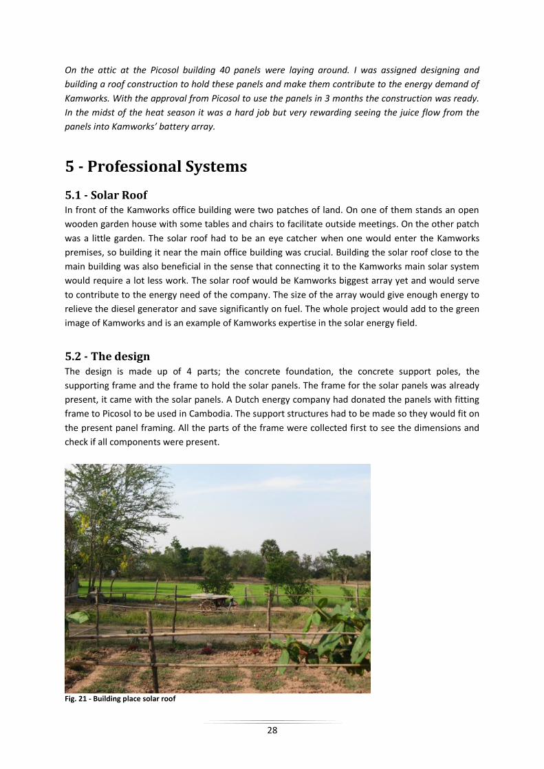
In front of the Kamworks office building were two patches of land. On one of them stands an open
wooden garden house with some tables and chairs to facilitate outside meetings. On the other patch
was a little garden. The solar roof had to be an eye catcher when one would enter the Kamworks
premises, so building it near the main office building was crucial. Building the solar roof close to the
main building was also beneficial in the sense that connecting it to the Kamworks main solar system
would require a lot less work. The solar roof would be Kamworks biggest array yet and would serve
to contribute to the energy need of the company. The size of the array would give enough energy to
relieve the diesel generator and save significantly on fuel. The whole project would add to the green
image of Kamworks and is an example of Kamworks expertise in the solar energy field.
5.2 - The design The design is made up of 4 parts; the concrete foundation, the concrete support poles, the
supporting frame and the frame to hold the solar panels. The frame for the solar panels was already
present, it came with the solar panels. A Dutch energy company had donated the panels with fitting
frame to Picosol to be used in Cambodia. The support structures had to be made so they would fit on
the present panel framing. All the parts of the frame were collected first to see the dimensions and
check if all components were present.
Fig. 21 - Building place solar roof

29
Now a simple support structure was designed. Relying heavily on local building knowledge and
working with the materials available a CAD design would serve as a building plan. The local people
here in Cambodia often build their own houses with the help of family and the community, basic
building knowledge is widespread. The foreman at Kamworks helped with designing the foundation.
The whole structure would be supported on 4 concrete poles. These poles needed to be well secured
in the ground. We determined that a hole of at least 1x1x1m would hold the poles in place. These
dimensions are also used in the building of houses and would suffice as a strong foundation. On top
of the concrete poles 4 I-profiles are mounted to support the aluminum panel frames. But on the
local steel market only C-frames were available in correct size. The decision was made to make an I-
profile out of 2 C-profiles by bolting and welding them back to back. The whole design looks like Fig.
22 and Fig. 23 and has total dimensions of 6mX4.3m. The design is 3.7meters at its highest point and
2.4 at the front.
Fig. 22 - CAD design framework Fig. 23 - Overall CAD design
5.3 - Connecting the parts To connect the different parts of the structure there were two major points. One is how to connect
the concrete pole to the supporting I-profiles. And two how to connect the panel framing to the I-
profiles. To connect the panel framing to the I-profiles would not be difficult. The frame came with
foots which could be bolted to the I-profile.
Fig. 24 - Slope of the roof
The concrete poles will be connected by casting 4 wire threads into the top of the pole. The pole will
have 4 protruding threads on top in which the I-profile will fit so it can be bolted.

30
5.4 - Other design features In order to capture as much sunlight as possible the roof will have an inclination of 17 degrees. This is
the optimal tilt angle for Kamworks location as determined by [7]. The design was kept very open, this
way it would look more professional and give the impression of sitting under the open sky. The type
of panels were glass-glass, so you could see though a big part of the panels. After the design was
approved by the managing directors I could start to make a building plan and start with the
preparations for construction.
5.5 - Building The build started in the beginning of April in the midst of the heat season. The average outside
temperature was 35°C, not a very comfortable temperature to be working outside. After the
construction site was cleared and leveled the foundation was first to be constructed. The building
schedule would have the Solar Roof operational in 2 months.
5.5-1 - Foundation
For the foundation 4 holes needed to be dug. The placement of the holes would be crucial for the
later construction and with no modern land measurement tools the correct positions were
determined with rope. The position of the first hole is not very important as long as the other 3 are
perfectly aligned with the first one.
Fig. 25 - Foundation schematic Fig. 26 - First foundation hole dug
The ground was very dry and difficult to dig in. Water was used to make the soil more soft. A layer of
water is sprayed in the hole and when the soil had absorbed the water, the moist mud could be
extracted more easily. This process was repeated until the depth of 1 meter was reached. To keep
the foundation from shifting big stones are pushed in the bottom of each hole. On top of the stones
a layer of 10cm concrete is poured. This gives a strong and flat surface to construct the poles on.
5.5-2 - Concrete Poles
The concrete poles are contracted using an iron mold. The mold is 3 meters high, this means that the
higher poles on the backside need to be poured in 2 stages. The poles need to be exactly straight and
exactly equal height. But before the molds can be placed and the concrete mixed a steel skeleton had
to be woven to support the concrete.
The whole process was labor intensive and very different from western building, where most iron
frames are delivered prefab. Once the rebar was finished they were placed in the holes standing on
31
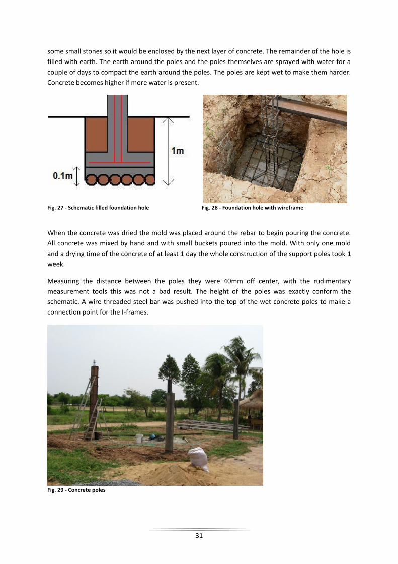
some small stones so it would be enclosed by the next layer of concrete. The remainder of the hole is
filled with earth. The earth around the poles and the poles themselves are sprayed with water for a
couple of days to compact the earth around the poles. The poles are kept wet to make them harder.
Concrete becomes higher if more water is present.
Fig. 27 - Schematic filled foundation hole Fig. 28 - Foundation hole with wireframe
When the concrete was dried the mold was placed around the rebar to begin pouring the concrete.
All concrete was mixed by hand and with small buckets poured into the mold. With only one mold
and a drying time of the concrete of at least 1 day the whole construction of the support poles took 1
week.
Measuring the distance between the poles they were 40mm off center, with the rudimentary
measurement tools this was not a bad result. The height of the poles was exactly conform the
schematic. A wire-threaded steel bar was pushed into the top of the wet concrete poles to make a
connection point for the I-frames.
Fig. 29 - Concrete poles

32
5.5-3 - I-Profiles
In Phnom Penh no I-profiles of the dimensions needed could be bought so 2 C-frames were welded
back to back making the I-profile needed. The C-frames came in 6m length, precisely the length
required. The I-profiles had to be mounted on the concrete poles. Kamworks does not have any
mechanical movers so the profiles had to be lifted by hand. With scaffolding on both sides of the
construction side and careful coordination the heavy profiles were lifted by hand into their position.
Before the I-profiles were mounted we coated them and painted them white. The whole structure
would be white and painting the profiles once up would be a lot harder than painting them on the
ground.
5.5-4 - Solar Panel Framing
The framing for the 40 solar panels consisted of 6 aluminum frames with cross-sections. With the I-
profiles mounted the aluminum frames could be assembled quickly. Every aluminum frame has two
foots on the far ends to connect to the I-profile. After fitting in place the holes are marked and the
frame has to be taken down to drill the holes. This process was repeated 6 times until the whole
frame was assembled and bolted to the construction.
Fig. 30 – Construction without panels
After all the large beams were in place the cross section frames could be installed. When all the cross
sections were installed also the highest point was reached.
5.5-5 - Mounting the Panels
Before all the panels could be installed they had to be tested. Every panel was tested by measuring if
it operated at 12V and whether it was producing current. The panels are glass-glass panels. The solar
cell sits in between 2 glass plates. This makes the panels transparent in between the cells but also
makes them heavy. All the panels came from The Netherlands and some were broken in transport,
the glass was broken or the connection wires were broken off. When all the panels were in place the
aluminum beams were quite stressed. The weight of every panels was underestimated and although
the structure was strong enough we decided to reinforce it to be sure that it would last also through

33
the heavy weather during the wet season. The reinforcement would be done by mounting 3 extra I-
profiles. Two profiles on either side from the back to the front and one through the middle, parallel
to the once already installed, to support the aluminum solar panels framing.
Fig. 31 – Finished construction with solar panels
5.5-6 - Connecting the panels
To make the Solar Roof compatible with the Kamworks system it had to be connected the right way.
The Kamworks system operates at 48V. A single panel gives 12V, with a total of 40 panels 4 parallel
rows of 10 panels needed to be connected in series to produce 48V output. The connection scheme
looks like Fig. 32. A thick cable was drawn from the Kamworks systems charge controller to the Solar
Roof. Once connected the 3,2kWp system was operational.
Fig. 32 - Solar panels schematic
34
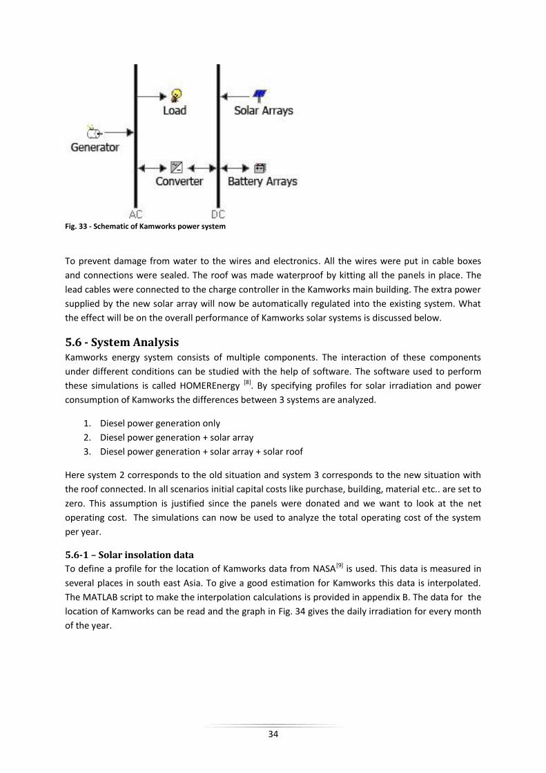
Fig. 33 - Schematic of Kamworks power system
To prevent damage from water to the wires and electronics. All the wires were put in cable boxes
and connections were sealed. The roof was made waterproof by kitting all the panels in place. The
lead cables were connected to the charge controller in the Kamworks main building. The extra power
supplied by the new solar array will now be automatically regulated into the existing system. What
the effect will be on the overall performance of Kamworks solar systems is discussed below.
5.6 - System Analysis Kamworks energy system consists of multiple components. The interaction of these components
under different conditions can be studied with the help of software. The software used to perform
these simulations is called HOMEREnergy [8]. By specifying profiles for solar irradiation and power
consumption of Kamworks the differences between 3 systems are analyzed.
1. Diesel power generation only
2. Diesel power generation + solar array
3. Diesel power generation + solar array + solar roof
Here system 2 corresponds to the old situation and system 3 corresponds to the new situation with
the roof connected. In all scenarios initial capital costs like purchase, building, material etc.. are set to
zero. This assumption is justified since the panels were donated and we want to look at the net
operating cost. The simulations can now be used to analyze the total operating cost of the system
per year.
5.6-1 – Solar insolation data
To define a profile for the location of Kamworks data from NASA[9] is used. This data is measured in
several places in south east Asia. To give a good estimation for Kamworks this data is interpolated.
The MATLAB script to make the interpolation calculations is provided in appendix B. The data for the
location of Kamworks can be read and the graph in Fig. 34 gives the daily irradiation for every month
of the year.

35
Fig. 34 - Global monthly horizontal Radiation
From Fig. 34 the lower clearance index indicates the monsoon season were more sunlight will be
stopped from hitting the panels by the rainclouds. The average yearly radiation is 5.21 with an
average clearance of 0.531.
5.6-2 – Power consumption
In order to estimate the power consumption of Kamworks several assumptions are made to create a
realistic power consumption profile. In the nighttime a constant power consumption of 200W is
assumed. This power will be used for lighting and equipment that is always connected. Then during
the course of the morning the power consumption gradually increases toward 2kW at noon. During
the lunch break the power consumption is lower and for the afternoon, which is the time most
power tools are used, the consumption is the highest. A profile of the modeled power consumption
is provided in Fig. 35. The profile is randomized slightly for different days. This will model the effect
of power consumption peaks when for example welding equipment is used and power consumption
drops during the holidays. The monthly power consumption is given in Fig. 36.
Fig. 35 - Kamworks daily powerconsumption

36
Fig. 36 - Seasonal power consumption profile
The modeled power profile gives an averaged power consumption of 24.1 kWh/d with 5.84 kW
peaks. The capacity of the solar arrays is not sufficient to also provide for the peaks. When high
power consuming equipment is used (e.g. welding equipment) the generator has to be started.
Therefore the power consumption profile models the real situation satisfactory.
5.6-3 – Equipment modeling
The overall system is being modeled as shown in Fig. 33. For every part certain variables have to be
defined in order to make the simulations. These values are discussed here. To model the different
solar arrays only one panel has to be modeled. Once the maintenance costs and capacity are defined
the overall PV capacity can be entered and the corresponding number of panels is used to make the
simulation. Also the slope of 17 degrees was taken into account, with no tracking system. The PV
panels provide DC-power and the main load is AC-power, cell phone charges and other very small DC
loads are neglected. The energy must thus be converted to be used, the same holds the other way
around. When the diesel generator is running and the power is not completely used by the load then
the converter (with build in charge controller) will charge the batteries. The converter has a
maximum capacity of 2.0kW and works for AC/DC and DC/AC conversion. For the generator itself it
was difficult to find a good model representations. First because the generator was old and the rated
power was not reached anymore. Second, detailed analysis on both fuel consumption and
maintenance costs had never been performed. To best model the generator a standard 15kW model
was used. The efficiency curve of the generator is shown in Fig. 37. A minimum load ratio of 30% was
used, with a 0.2$/h maintenance overhead. Diesel price was determined at 0.9 $/L [10], and held
constant for all 3 scenarios.
Fig. 37 - Efficiency curve generator

37
The batteries can best be defined by a capacity curve and a lifetime curve. These graphs will model
the behavior of the batteries. Since Kamworks uses deep-cycle forklift truck these type of batteries
are modeled. We want to maximize the lifetime of the battery array. From Fig. 38 and Fig. 39 can be
read that the optimal depth of discharge is <20%. For this value the lifetime throughput and the
cycles to failure are maximized.
Fig. 38 - Battery characteristics, Capacity vs. Discharge current
Fig. 39 - Battery characteristics, Cycles to Failure vs. Depth of Discharge
5.6-4 - Results
To analyze the results the simulations for the 3 different cases as states in section 5.6 will be
discussed. It is clear that the scenario with both solar array and solar roof will present the lowest
operating costs and diesel consumption. We will start by looking at the scenario when only a diesel
generator is used to provide power for Kamworks.
In this scenario the monthly average power production looks as in Fig. 40. The renewable fraction is
of course zero and the price per produced kilowatt is 0.718$. Per year the generator will use
approximately 4500 liters of diesel in 1720 operating hours.
38
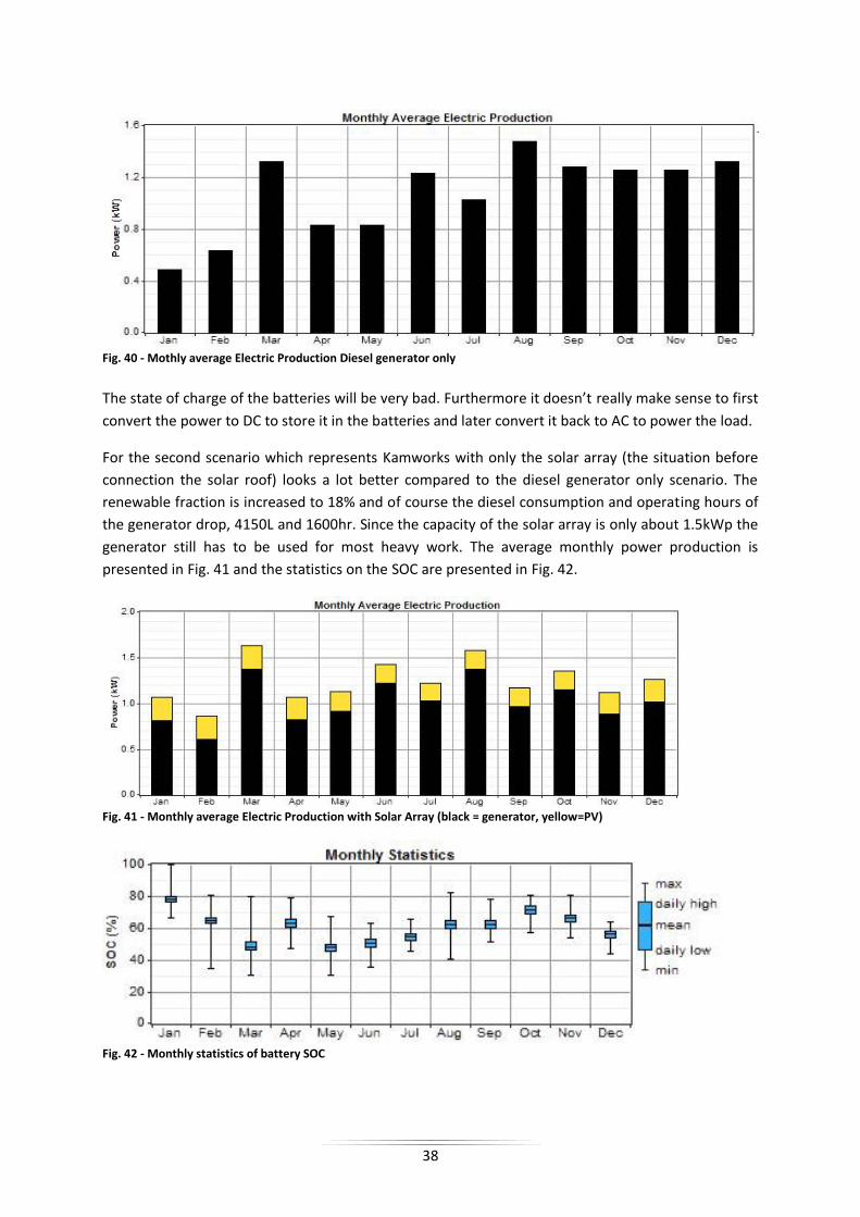
Fig. 40 - Mothly average Electric Production Diesel generator only
The state of charge of the batteries will be very bad. Furthermore it doesn’t really make sense to first
convert the power to DC to store it in the batteries and later convert it back to AC to power the load.
For the second scenario which represents Kamworks with only the solar array (the situation before
connection the solar roof) looks a lot better compared to the diesel generator only scenario. The
renewable fraction is increased to 18% and of course the diesel consumption and operating hours of
the generator drop, 4150L and 1600hr. Since the capacity of the solar array is only about 1.5kWp the
generator still has to be used for most heavy work. The average monthly power production is
presented in Fig. 41 and the statistics on the SOC are presented in Fig. 42.
Fig. 41 - Monthly average Electric Production with Solar Array (black = generator, yellow=PV)
Fig. 42 - Monthly statistics of battery SOC

39
The state of charge of the batteries is on a yearly average around 60%. This is lower than the optimal
SOC. Adding extra PV-capacity will improve the SOC of the battery array and further lower the
operating costs of the power producing system of Kamworks. The operating costs and energy price
are 4072$/yr and 0.542$/kWh respectively.
The current situation at Kamworks is simulated by scenario 3. This scenario represents the diesel
generator, the solar array and the solar roof connected to the system. The solar roof has a capacity of
3.2 (kWp) which is added to the total PV-capacity for the simulation. The addition of this capacity has
a very beneficial influence on all parameters. First of all the renewable fraction is 63%, more than
double that of the old situation. The cost of electricity is further reduced to 23.2 cents a kilowatt! The
average monthly power production is given in Fig. 43
Fig. 43 - Monthly average Electric Production with Solar Array and Solar Roof (black = generator, yellow=PV)
Fig. 44 - Monthly statistics of battery SOC
As can be seen in Fig. 44 the SOC of the battery array is now averaged around 80% and
corresponding to the optimal discharge of <20%. The annual operating costs are half that of the old
system and also the diesel consumption and operating hours are drastically reduced. Still the
generator has to be used to provide enough power for welding and other high power consuming
machinery. A higher power converter might be a solution but the cost benefit of this option is not
analyzed here. A summary of the simulations is given in Table 3.
System 1 System 2 System 3
Operating Costs [$/yr] 6312 4072 2042
Cost of Electricity [$/kWh] 0.718 0.542 0.232
Renewable Faction 0 0.18 0.63
Diesel consumption [L] 4429 4151 1724
Generator hours [h.] 1719 1604 624 Table 3 - Overview of simulation results

40
5.7 - Conclusion From the beginning we worked very hard on the solar roof. The completion of the structure was very
satisfying. Although we didn´t keep the schedule of 2 months, the result was the same. During the
building process I learned a lot of practical techniques, building in Cambodia is a lot different than in
Europe. No building permits necessary and safety regulations are non-present. Working in the mid-
day sun was never pleasant but with a result that can be seen from Google earth all the hardships
were soon forgotten. The new power supply reduced Kamworks dependence on their diesel
generator. The solar roof more than doubled Kamworks solar capacity, and also provides a nice place
to receive guests and visitors in a high tech environment in a place where it is least expected. The
build was technically not very hard but the practical insights learned from the process are invaluable.
Learning the local building techniques and working in an international team made this project very
rewarding and insightful. Software analysis done with HomerENERGY showed that the new solar roof
not only increased the ‘greenness’ of Kamworks but also resulted in an overall better performing and
cheaper power system.
In this chapter only the construction and analysis of the solar roof is discussed. In the course of my
internship I have worked on 2 other projects falling in the category of professional systems.
These projects are:
Tracking system for Solar Battery Charging Station.
This is a project started by Vasileios Antonopoulos aims at phasing out diesel generator use
for charging of batteries. For more information: [11]
Kingdom Brewery Solar System
Peter Brongers a Dutch entrepreneur started a beer brewery in Phnom Penh and requested
Kamwork to see if installing solar capacity would be beneficial. [12]

41
6 - Conclusion
Arriving in Cambodia in the first week of the new year I was picked up by one of the students already
working for Kamworks. A nice and comfortable way to get your first impressions. The first 3 months
of my internship I lived in the Solar Campus, very basic housing powered by solar energy. While the
showering with a little bucket took some getting used to the life in the province was very nice. We
had a fun group and worked together on our separate projects. I started my internship designing
molds for the solar home system. The designs were send for manufacturing to Vietnam and I could
pick them up some time later. A working trip to Saigon, an always welcome distraction and my first
experience with the full blown craziness of south east Asia. From the iron mold we made the plastic
molds for the Solar Home System and we pulled some nice quality products from the molds. It’s a
very good feeling to see that the things you design on your computer work out in practice. After a
successful mold design, I was assigned to also make the new molds for a new type of panel support.
The old panel support was not able to support different dimension panels and with the new design,
involving an adjustable base this became possible.
Kamworks advocates itself as a green company, but when arriving in the morning the slow stokes of
the diesel generator can be heard from behind the building. A solution had to be found and with 40
donated solar panels some concrete and steel my next project was born. The next couple of months
we worked hard in the burning sun to construct a solar roof to make Kamworks a true self supplying,
green company. We dug deep foundation holes, poured concreted welded steel and constructed roof
framing, a dream of every mechanical engineer. And the good thing here in Cambodia; no building
permits required. You got the steel you got the tools, you can start building. The result was a fully
operational solar array which can be spotted with Google earth.
The last months I spend reviving a shelved project namely the Solar TV. A product with high
potentiality since the people here in Cambodia all seem to want a cheap but good solution for
watching TV. Since the solar TV runs on 12V it can work with the widely used car batteries and can
also work together with the Solar Home System. We build 5 prototypes for field-testing, to filter out
all the flaws before starting real production.

42
References
[1] Justin Corfield - The History of Cambodia, The Greenwood history of modern nations - 2009
[2] "Cambodian Genocide Program | Yale University". Yale.edu. 2007-07-18.
http://www.yale.edu/cgp/ Retrieved 2010-07-27.
[3] Cambodia Energy Sector Strategy - United Nations - 2010
[4] Renewable Energy Development in Cambodia - Institute of Technology of Cambodia
[5] Miro Zeman - Introduction to photovoltaic solar energy - Delft University
[6] Third generation photovoltaics Gregory F. Brown and Junqiao Wu - University of California,
Berkeley - 2009
[7] Optimal panel slope Cambodia: http://solarelectricityhandbook.com/solar-angle-calculator.html/
Retreived 2010-11-10.
[8] Energy analysis software: http://homerenergy.com/ Retreived 6-8-2010
[9] NASA Langley Research Center Atmospheric Science Data Center; New et al. 2002
http://eosweb.larc.nasa.gov/ Retreived 1-5-2010
[10] Dieselprice Cambodia: http://www.tradingeconomics.com/cambodia/pump-price-for-diesel-
fuel-us-dollar-per-liter-wb-data.html/ Retreived 9-10-2010
[11] Students for Sustainability. SBCS summary:
http://www.students4sustainability.nl/_media/SBCS/Building%20a%20Solar%20Battery%20Charging
%20Station%20in%20Kandal%20province,%20Cambodia.pdf
[12] http://www.kingdombreweries.com/

43
Appendix A – Database Cambodia
Database Cambodia Source: NASA Langley Research Center Atmospheric Science Data Center; New et al. 2002
All data in this database is based on monthly averages measured on 50 sites in and around Cambodia. A cubic
interpolation scheme is used to create contour overlays. Monthly contourplots can be requested by sending an email to:
Irradiation [yearly average] Max: 5.25 Min: 4.35 Avg: 5.00
Clearance corrected irradiation [yearly average] Max: 2.90 Min: 2.00 Avg: 2.62

44
Precipitation [yearly average] Max: 287 Min: 84 Avg: 148
Temperature [yearly average] Max: 26.62 Min: 23.05 Avg: 25.58

45
Windspeed [yearly average] Max: 6.81 Min: 1.76 Avg: 3.68
Information disclaimer
This database is intended to serve general information purposes only. The information provided in this database is not intended as an advice in
any way. The information in this database is composed and maintained with continuous care and attention by Kamworks. However, Kamworks
cannot give any warranty as to the accuracy or completeness of the information in this database. Therefore no rights can be derived from the
information in this database. Kamworks is under no circumstances liable for damages of whatever nature, in anyway resulting from the use of this
database or resulting from or related to the use of information presented on or made available through this database or damages resulting from
the non-availability of this database

46
Appendix B – MATLAB interpolation script
1. clc; 2. clear all; 3. 4. filename = 'DATASET_CAMBODJA_SP.txt'; 5. month = 12; 6. 7. data = importdata(filename); 8. 9. 10. N = 46; %number of datapoints 11. GD = 75; %gird density 12. 13. j=1 14. 15. for i=1:N 16. P(i) = DP; 17. P(i).lat = data(j,1:3); 18. P(i).long = data(j,4:6); 19. P(i).insol = data(j,7:end); 20. P(i).clr = data(j+1,7:end); 21. P(i).temp = data(j+2,7:end); 22. P(i).wind = data(j+3,7:end); 23. P(i).precip = data(j+4,7:end); 24. j=j+5; 25. End 26. 27. %Size figure window 28. scrsz = get(0,'ScreenSize'); 29. hf = figure('Position',[scrsz(3)/2-400 scrsz(4)/2-300 800 600]); 30. 31. %Place image on axis 32. I=imread('MAP2.jpg'); 33. S = size(I); 34. h = warp(I); 35. alpha(h, 0.7); 36. 37. %Labels 38. %title('Insolation Cambodja'); 39. axis([0 S(2) 0 S(1)]); 40. 41. hold on; 42. 43. R = 7; 44. for i=1:N 45. x(i) = (P(i).long(1)+P(i).long(2)/60+P(i).long(3)/3600-101.9)*171; 46. y(i) = S(1)-(P(i).lat(1)+P(i).lat(2)/60+P(i).lat(3)/3600-10.35)*180; 47. 48. fill(x(i)+R*sin(0:pi/6:2*pi),y(i)+R*cos(0:pi/6:2*pi), 'r'); 49. z(i) = P(i).wind(month); 50. end; 51. 52. xlin = linspace(min(x),max(x),GD); 53. ylin = linspace(min(y),max(y),GD); 54. 55. [X,Y] = meshgrid(xlin,ylin); 56. Z = griddata(x,y,z,X,Y,'cubic'); 57. max(z) 58. min(z) 59. mean(z) 60. caxis([0, 300]); 61. [c, h1] = contourf(X, Y, Z); %interpolated 62. clabel(c,h1); 63. h2 = colorbar; 64. ylabel(h2,'mm'); 65. axis off; 66. 67. view(0, 90);

48
Appendix D – Part and Costs list Solar TV
# PART REF QT BUY/
MAKE MATERIAL EST. PPU TOTAL TOOLING SUPPLIER
Main Assembly
1 Body Front 1 make ABS $1,20 $1,20 $2.700 Tan-Y
2 Body Back 1 make ABS $1,20 $1,20 $2.700 Tan-Y
3 LCDTV PCB 1 buy $13,5 $13,50 Top-Tech
4 Inverter 1 buy $2,25 $2,25 Top-Tech
5 PCB Interface 1 buy $0,85 $0,85 Top-Tech
6 IR PCB 1 buy $0,25 $0,25 Top-Tech
7 Speaker 2 buy $0,10 $0,20
8 Buttons 1 make ABS $0,10 $300,00 Tan-Y
9 IR Inset 1 make PC $0,10 $500,00 Tan-Y
10 Speakerplate 1 buy nylon $0,02 $0,02
LCD Assembly
11 LCD Screen 1 buy $15,00 $15,00 Various
12 LCD Backplate 1 make PS $0,50 $0,50 $600,00 Tan-Y
Foot Assembly
13 Foot 1 make ABS $0,70 $1.200,00 Tan-Y
14 Frictioin Hinge 2 buy $0,80
Other
15 M3x20 Screws 12 buy $0,01 $0,12
16 M2x5 Electronics Screws 5 buy $0,01 $0,05
17 M2x3 LCD-Plate Screws 8 buy $0,01 $0,08
18 Remote 1 buy $2,25 $2,25
Total component price $39,17
Assembly $2,00
Transport 5% $1,96
Marketing 5% $1,96
Total investment (tooling) $8.000,00
Production price $45,09
Profit margin 20% $9,02
Retail price $54,10


