117
INTERRANGER DPS 300 Instruction Manual December 2001 INTERRANGER DPS 300

INTERRANGER DPS 300
Instruction Manual December 2001
INT
ER
RA
NG
ER
DP
S3
00

© Siemens Milltronics Process Instruments Inc. 2001
Safety Guidelines
Warning notices must be observed to ensure personal safety as well as that of others, and to protect the product and the connected equipment.These warning notices are accompanied by a clarification of the level of caution to be observed.
Qualified Personnel
This device/system may only be set up and operated in conjunction with this manual. Qualified personnel are only authorized to install andoperate this equipment in accordance with established safety practices and standards.
Warning: This product can only function properly and safely if it is correctly transported, stored, installed, set up, operated, and maintained.
Note: Always use product in accordance with specifications.
Copyright Siemens Milltronics ProcessInstruments Inc. 2000. All Rights Reserved
Disclaimer of Liability
This document is available in bound version and inelectronic version. We encourage users to purchaseauthorized bound manuals, or to view electronic versions asdesigned and authored by Siemens Milltronics ProcessInstruments Inc. Siemens Milltronics Process InstrumentsInc. will not be responsible for the contents of partial orwhole reproductions of either bound or electronic versions.
While we have verified the contents of thismanual for agreement with the instrumentationdescribed, variations remain possible. Thus wecannot guarantee full agreement. The contents ofthis manual are regularly reviewed andcorrections are included in subsequent editions.We welcome all suggestions for improvement.
Technical data subject to change.
MILLTRONICS®is a registered trademark of Siemens Milltronics Process Instruments Inc.
Contact SMPI Technical Publications at the following address:
Technical PublicationsSiemens Milltronics Process Instruments Inc.1954 Technology Drive, P.O. Box 4225Peterborough, Ontario, Canada, K9J 7B1Email: [email protected]
For the library of SMPI instruction manuals, visit our Web site: www.milltronics.com
PL-566 3 InterRanger DPS 300
TABLE OF CONTENTS
Specifications ............................................................................................................ 5
Electronics.............................................................................................................. 5
Programmer ........................................................................................................... 6
Transducer............................................................................................................. 6
Options................................................................................................................... 7
Cable...................................................................................................................... 8
Introduction................................................................................................................ 9
About This Manual ................................................................................................. 9
About The InterRanger DPS 300......................................................................... 10
Important InterRanger DPS 300 Features ........................................................... 12
Programmable Features ...................................................................................... 13
As a System......................................................................................................... 14
Application Planning................................................................................................ 15
Circular Clarifiers ................................................................................................. 15
Rectangular Clarifiers .......................................................................................... 17
Application Example ................................................................................................ 21
Installation................................................................................................................ 23
Location................................................................................................................ 23
Optional Mounting Assembly ............................................................................... 24
Optional Skimmer Guard ..................................................................................... 27
Transducer Mounting ........................................................................................... 32
Assembly.............................................................................................................. 34
Communication .................................................................................................... 38
Level System Synchronization............................................................................. 39
Power ................................................................................................................... 39
Programming .......................................................................................................... 41
Display ................................................................................................................. 41
Keypad – Program Mode..................................................................................... 42
Programming Security ......................................................................................... 44
Quick Start Parameters........................................................................................... 45
Operation.................................................................................................................. 49
Display ................................................................................................................. 49
Keypad – Run Mode ............................................................................................ 50
System Performance Evaluation.......................................................................... 51
Performance Test Results ................................................................................... 52
InterRanger DPS 300 4 PL-566
Application Parameters.......................................................................................... 53
Volume Parameters (P050 to P055) ................................................................... 53
Reading Parameters (P060 to P062) .................................................................. 55
Failsafe Parameters (P070 to P072) ................................................................... 56
Relay Parameters (P100 to P104, P110 to P113, P129) .................................... 58
mA Output Parameters (P200 to P203, P210 to P215, P219) ............................ 64
Enhancement Parameters...................................................................................... 69
Data Logging Parameters (P300 and P302) ....................................................... 69
Profile Records (P330 to P337)........................................................................... 70
Installation Records (P340 to P342).................................................................... 73
Range Calibration Parameters (P650 to P654)................................................... 73
Temperature Compensation Parameters (P660 to P664)................................... 75
Rate Parameters (P700 to P707) ........................................................................ 76
Measurement Verification Parameters (P710 to P713)....................................... 78
Display Parameters (P730 to P733, P740) ......................................................... 79
Peripheral Communication Support Parameters (P740 to P749)........................ 80
SmartLinx® Parameters (P790 to P792)............................................................ 82
Echo Processing Parameters (P800 to P807)..................................................... 82
Advanced Echo Processing (P810 to P853) ....................................................... 84
Test Parameters (P900 to P913) ........................................................................ 91
Measurement Parameters (P920 to P923) ......................................................... 93
Master Reset (P999) ........................................................................................... 95
Technical Reference............................................................................................... 97
Transmit Pulse .................................................................................................... 97
Echo Processing ................................................................................................. 98
Distance Calculation............................................................................................ 99
Sound Velocity .................................................................................................... 99
Scanning ............................................................................................................. 99
Volume Calculation ........................................................................................... 100
Communication Support.................................................................................... 101
Maintenance.......................................................................................................... 105
Troubleshooting Guide ........................................................................................ 107
Default Parameter Settings.................................................................................. 111
Programming Charts ............................................................................................ 113
PL-566 5 InterRanger DPS 300
SPECIFICATIONS
Electronics
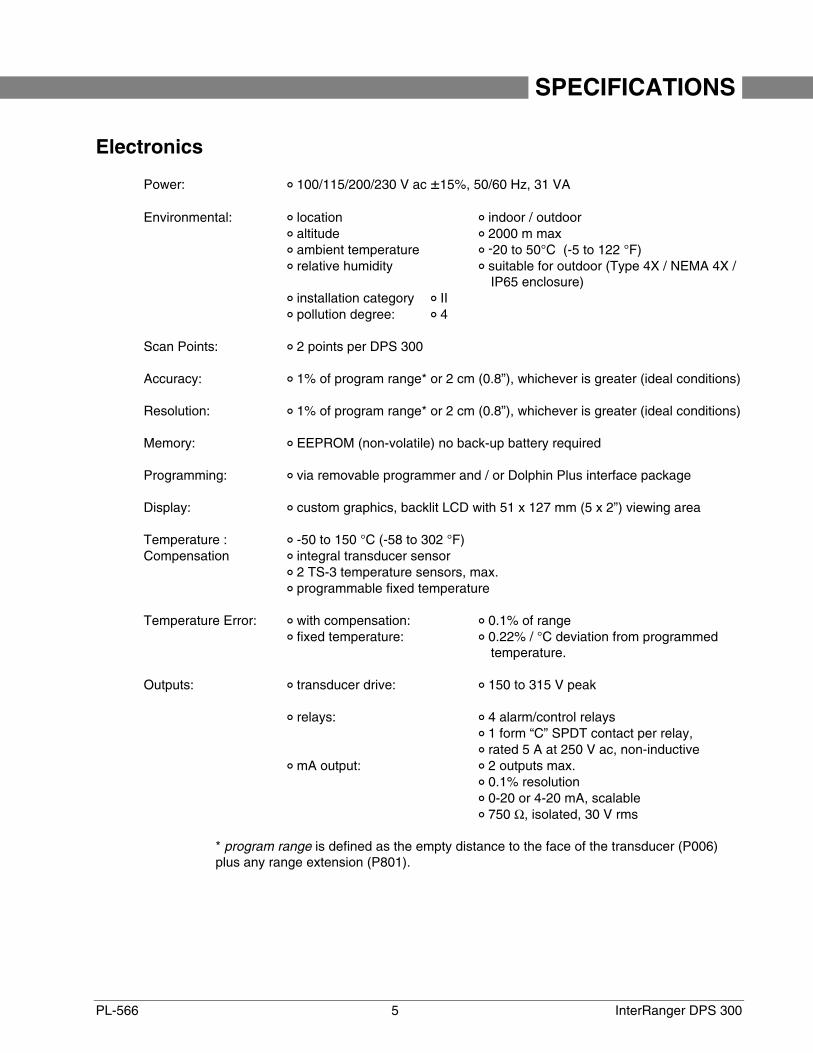
Power: 100/115/200/230 V ac ±15%, 50/60 Hz, 31 VA
Environmental: location indoor / outdoor altitude 2000 m max ambient temperature -20 to 50°C (-5 to 122 °F) relative humidity suitable for outdoor (Type 4X / NEMA 4X /
IP65 enclosure) installation category II pollution degree: 4
Scan Points: 2 points per DPS 300
Accuracy: 1% of program range* or 2 cm (0.8”), whichever is greater (ideal conditions)
Resolution: 1% of program range* or 2 cm (0.8”), whichever is greater (ideal conditions)
Memory: EEPROM (non-volatile) no back-up battery required
Programming: via removable programmer and / or Dolphin Plus interface package
Display: custom graphics, backlit LCD with 51 x 127 mm (5 x 2”) viewing area
Temperature : -50 to 150 °C (-58 to 302 °F)Compensation integral transducer sensor
2 TS-3 temperature sensors, max. programmable fixed temperature
Temperature Error: with compensation: 0.1% of range fixed temperature: 0.22% / °C deviation from programmed
temperature.
Outputs: transducer drive: 150 to 315 V peak
relays: 4 alarm/control relays 1 form “C” SPDT contact per relay, rated 5 A at 250 V ac, non-inductive
mA output: 2 outputs max. 0.1% resolution 0-20 or 4-20 mA, scalable 750 Ω, isolated, 30 V rms
* program range is defined as the empty distance to the face of the transducer (P006)plus any range extension (P801).
PL-566 6 InterRanger DPS 300
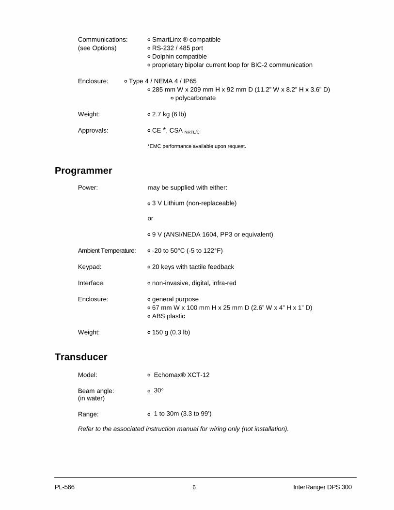
Communications: ! SmartLinx ® compatible(see Options) ! RS-232 / 485 port
! Dolphin compatible! proprietary bipolar current loop for BIC-2 communication
Enclosure: ! Type 4 / NEMA 4 / IP65! 285 mm W x 209 mm H x 92 mm D (11.2” W x 8.2” H x 3.6” D)
! polycarbonate
Weight: ! 2.7 kg (6 lb)
Approvals: ! CE *, CSA NRTL/C
*EMC performance available upon request.
Programmer
Power: may be supplied with either:
! 3 V Lithium (non-replaceable)
or
! 9 V (ANSI/NEDA 1604, PP3 or equivalent)
Ambient Temperature: ! -20 to 50°C (-5 to 122°F)
Keypad: ! 20 keys with tactile feedback
Interface: ! non-invasive, digital, infra-red
Enclosure: ! general purpose! 67 mm W x 100 mm H x 25 mm D (2.6” W x 4” H x 1” D)! ABS plastic
Weight: ! 150 g (0.3 lb)
Transducer
Model: ! Echomax® XCT-12
Beam angle: ! 30°(in water)
Range: ! 1 to 30m (3.3 to 99’)
Refer to the associated instruction manual for wiring only (not installation).

PL-566 7 InterRanger DPS 300
Options
Skimmer Guard for protecting the transducer and allowing it to slide over the skimmer as it
passes.
Mounting Assembly for securing and positioning the transducer in the clarifier.
Temperature Sensor: model TS-3
Buffered Interface Converter: BIC-II, DPS 300 bipolar communication current loop to remote RS232 or
RS422 port
SmartLinx® Modules protocol specific modules for interface with popular industrial
communication systems. Refer to associated product documentation.
Dolphin Plus: Milltronics Windows®-compatible interface and infrared ComVerter link
. Refer to associated product documentation.
Cable: to suit transducer, temperature sensor, instrumentation and communication
Skimmer Guard
Model: Type A for 20cm (8”) skimmers Type B for 40cm (16”) skimmers
Temperature: -40 to 80 °C (-40°C to 176°F)Construction: stainless steel hinged conduit with guard, and neoprene hinge bootConnection: transducer: 1” NPT or BSP coupling
conduit: ¾” NPT or BSP couplingArticulation: ± 90° off verticalWeight: Type A: 1.4 kg (3 lb)
Type B: 2.1 kg (5 lb)
Mounting Assembly
Application: railings, typically 50mm dia. pipe or less, 2 rails spaced 432 to610mm (17 to 24”)apart on centre
Temperature: -40 to 80°C (-40 to 176°F)Construction: epoxy coated aluminum, with stainless steel hardwareWeight: 6.5 kg (15 lbs)
PL-566 8 InterRanger DPS 300
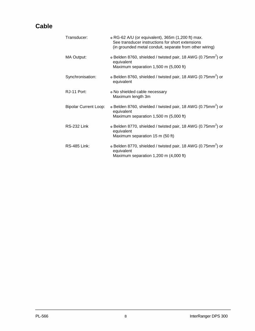
Cable
Transducer: ! RG-62 A/U (or equivalent), 365m (1,200 ft) max. See transducer instructions for short extensions (in grounded metal conduit, separate from other wiring)
MA Output: ! Belden 8760, shielded / twisted pair, 18 AWG (0.75mm2) or equivalent Maximum separation 1,500 m (5,000 ft)
Synchronisation: ! Belden 8760, shielded / twisted pair, 18 AWG (0.75mm2) or equivalent
RJ-11 Port: ! No shielded cable necessary Maximum length 3m
Bipolar Current Loop: ! Belden 8760, shielded / twisted pair, 18 AWG (0.75mm2) or equivalent Maximum separation 1,500 m (5,000 ft)
RS-232 Link ! Belden 8770, shielded / twisted pair, 18 AWG (0.75mm2) or equivalent Maximum separation 15 m (50 ft)
RS-485 Link: ! Belden 8770, shielded / twisted pair, 18 AWG (0.75mm2) or equivalent Maximum separation 1,200 m (4,000 ft)

PL-566 9 InterRanger DPS 300
INTRODUCTION
About This Manual
This instruction manual provides information specific to the InterRanger DPS 300 (DualPoint Sludge) monitoring system.
Introduction introduces installers and operators to the DPS 300, with briefdescriptions of key features.
Installation provides a step by step procedure to install the DPS 300.
Programming defines program mode display and keypad functions, andgeneral programming information.
Quick Start Parameters details the minimum programming required to get started.
Operation defines RUN mode display and keypad functions, includingthe RUN mode entry procedure and performance evaluationrecommendations.
Application Parameters details the programmable features which may be used toalter Run mode display, failsafe, relay, and mA outputoperation.
Enhancement Parameters defines the programmable features used to enhance RUNmode operation. (Typically used as directed by theTroubleshooting Guide).
Technical Reference provides detailed information for complex features andprovides application examples.
Troubleshooting Guide provides a quick reference to installation modification andprogramming remedies to overcome challenging operatingconditions.
Specifications lists the environmental, physical, and operationalcharacteristics associated with the DPS 300.
Programming Chart provides a convenient space to record all programming forfuture reference.
InterRanger DPS 300 10 PL-566
About The InterRanger DPS 300
Note:The InterRanger DPS 300 is to be used only in the manner outlined in this instruction manual.
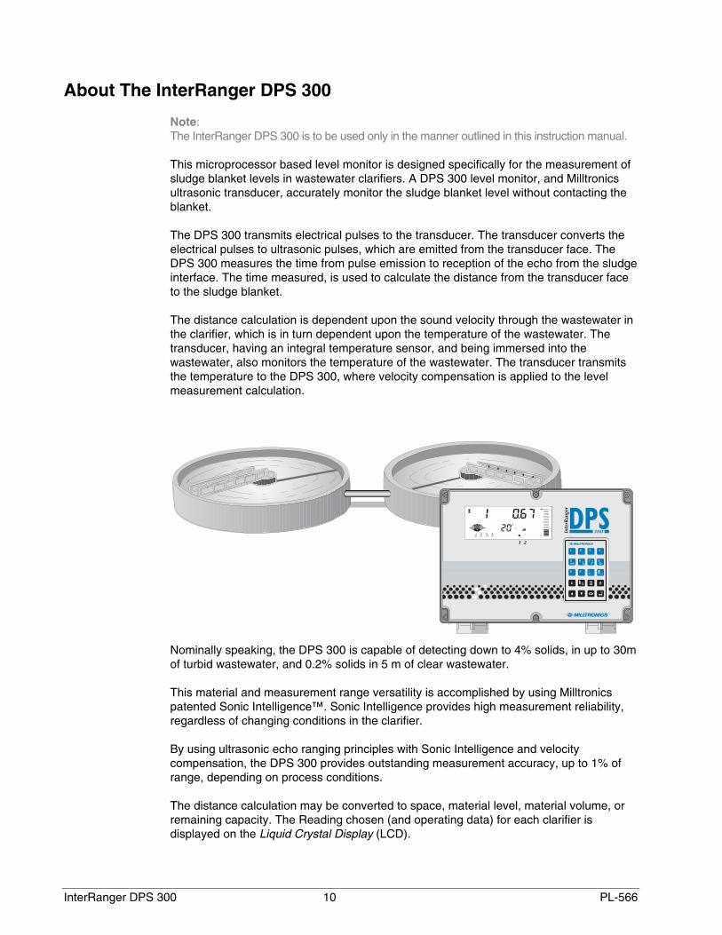
This microprocessor based level monitor is designed specifically for the measurement ofsludge blanket levels in wastewater clarifiers. A DPS 300 level monitor, and Milltronicsultrasonic transducer, accurately monitor the sludge blanket level without contacting theblanket.
The DPS 300 transmits electrical pulses to the transducer. The transducer converts theelectrical pulses to ultrasonic pulses, which are emitted from the transducer face. TheDPS 300 measures the time from pulse emission to reception of the echo from the sludgeinterface. The time measured, is used to calculate the distance from the transducer faceto the sludge blanket.
The distance calculation is dependent upon the sound velocity through the wastewater inthe clarifier, which is in turn dependent upon the temperature of the wastewater. Thetransducer, having an integral temperature sensor, and being immersed into thewastewater, also monitors the temperature of the wastewater. The transducer transmitsthe temperature to the DPS 300, where velocity compensation is applied to the levelmeasurement calculation.
Nominally speaking, the DPS 300 is capable of detecting down to 4% solids, in up to 30mof turbid wastewater, and 0.2% solids in 5 m of clear wastewater.
This material and measurement range versatility is accomplished by using Milltronicspatented Sonic Intelligence™. Sonic Intelligence provides high measurement reliability,regardless of changing conditions in the clarifier.
By using ultrasonic echo ranging principles with Sonic Intelligence and velocitycompensation, the DPS 300 provides outstanding measurement accuracy, up to 1% ofrange, depending on process conditions.
The distance calculation may be converted to space, material level, material volume, orremaining capacity. The Reading chosen (and operating data) for each clarifier isdisplayed on the Liquid Crystal Display (LCD).

PL-566 11 InterRanger DPS 300
The relays and mA outputs may be used as preset (or programmed as desired) toactivate alarms and/or operate remote monitoring equipment and/or process controlequipment.
As well, the DPS 300 may be connected to a Milltronics BIC-II (Buffered InterfaceConverter) to provide RS-232 and/or RS-422 communications for host computers,Distributed Control Systems, and special (capable of operating as a host device)Programmable Logic Controllers.
Programming can be done locally using the portable programmer keypad, or remotelythrough optional Dolphin software or SmartLinx®.
• The programmer transmits the keypad entries via infrared link to the DPS 300, and canbe removed when not in use.
• Dolphin allows programming either through the portable ComVerter and infrared link orhardwired via the RS-232/485 communication port.
• SmartLinx® provides protocol specific hardware and software for interface with popularindustrial communication systems.
DPS 300 Communication Overview
or
0/4—20mA(PLC or DCS)
SmartLinx®
RS-232 or 485
(local)
Bipolarcurrent loop
(remote)
RS-232 or 422 or
Plant-widecontrol system
network

InterRanger DPS 300 12 PL-566
Important InterRanger DPS 300 Features
Fixed Features
Enclosure: Corrosion resistant, dust and liquid tight.
Backlit LCD: Large digits for Reading and programming value displays.
Illuminated LCD insures readability under all lightingconditions.
Custom Graphic Symbols for continuous indication ofoperating conditions.
Programmer: 20 keys for easy access to programming and operatingfunctions.
Magnetic mounting and infrared interface permit removal onprogramming completion.
Scanning: Capable of scanning two clarifiers, with the addition of asecond transducer.
Communications: SmartLinx® Compatible
Communications ready when equipped with anappropriate Milltronics SmartLinx module.
Milltronics Peripherals
The communication port provides connection for RS-232, RS-485 or Milltronics bipolar current loop. Thecurrent loop provides remote communication viaMilltronics BIC II to the peripheral device. The BIC IIconverts the current loop to RS-232 or RS-422 signal
Dolphin Compatible Communications
Dolphin Plus is Milltronics Windows95®-compatiblesoftware. It offers local interface through the infraredComVerter, or remote connection through the RS-232 orRS-485 port. The software provides an easy means forprogramming, uploading, or downloading parameters.
Reliability: Sonic Intelligence™ ensures all measurements areaccurate and reliable.
Immune to power interruptions. All programming is storedindefinitely. Dynamic operating data is retained for one hourand updated immediately on power resumption.
PL-566 13 InterRanger DPS 300
Programmable Features
Typically, a very small percentage of the programmable features require operatoralteration. However, for demanding measurement requirements any operatorprogrammable feature may be adjusted as desired.
Following is a list of some of the features that make the DPS 300 easy to program, yetversatile enough to handle complex level measurement requirements.
General Features
Direct Access: Any operator programmable feature may be accesseddirectly.
Scroll Access: Single button “scroll forward”, single button “scroll back”, tokey features.
Operation: Select “level”,”space”,or ”distance”.
Material: Select “primary” or “secondary”; automatically adjusts echoprocessing for the type of clarifier.
Units: Display Readings in m, cm, mm, ft, in, %, or any other unitsdesired.
Additional Features (Use as Desired)
Failsafe: Numerous failsafe options for process control equipmentactivation.
Relays: 8 functions including level, rate of change, pump control,temperature and more.
Fixed or independent on/off setpoints
mA outputs: Based on level, space, or distance.
4 range selections, 0-20, 4-20, 20-0, or 20-4 mA.
Adjustable range and over-range limits.
InterRanger DPS 300 14 PL-566
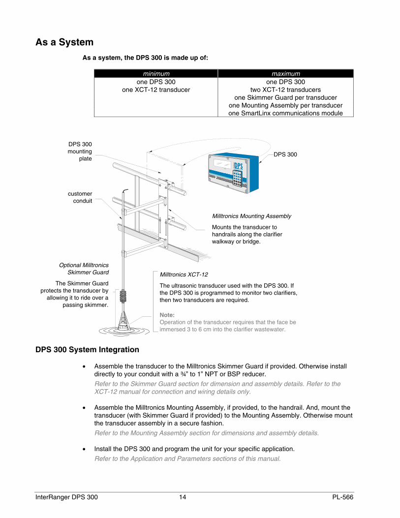
As a SystemAs a system, the DPS 300 is made up of:
minimum maximumone DPS 300 one DPS 300
one XCT-12 transducer two XCT-12 transducersone Skimmer Guard per transducer
one Mounting Assembly per transducerone SmartLinx communications module
DPS 300 System Integration
• Assemble the transducer to the Milltronics Skimmer Guard if provided. Otherwise installdirectly to your conduit with a ¾” to 1” NPT or BSP reducer.
Refer to the Skimmer Guard section for dimension and assembly details. Refer to theXCT-12 manual for connection and wiring details only.
• Assemble the Milltronics Mounting Assembly, if provided, to the handrail. And, mount thetransducer (with Skimmer Guard if provided) to the Mounting Assembly. Otherwise mountthe transducer assembly in a secure fashion.
Refer to the Mounting Assembly section for dimensions and assembly details.
• Install the DPS 300 and program the unit for your specific application.
Refer to the Application and Parameters sections of this manual.
DPS 300
Milltronics Mounting Assembly
Mounts the transducer tohandrails along the clarifierwalkway or bridge.
Optional MilltronicsSkimmer Guard
The Skimmer Guardprotects the transducer by
allowing it to ride over apassing skimmer.
customerconduit
Milltronics XCT-12
The ultrasonic transducer used with the DPS 300. Ifthe DPS 300 is programmed to monitor two clarifiers,then two transducers are required.
Note:Operation of the transducer requires that the face beimmersed 3 to 6 cm into the clarifier wastewater.
DPS 300mounting
plate

PL-566 15 InterRanger DPS 300
APPLICATION PLANNING The DPS 300 is designed to detect and measure the sludge blanket in up to twowastewater clarifiers. The basic requirements of a working DPS system are thetransducers and the associated electronics.
The electronics can be mounted at the clarifier or up to 365 m away from the transducer.Refer to DPS 300 Specifications in this manual.
The transducer is installed such that its face is immersed 3 to 6 cm in the clarifierwastewater.
Beyond these given requirements, a few practical aspects of the clarifier application andits operation are of particular concern.
Circular Clarifiers
There are several different types of circular clarifiers, but all operate in the same basicway and share common design features that will need to be considered when installingan InterRanger™ DPS 300.
Some of these considerations are:
Catwalk, Bridge or Walkway
Most circular tanks have a catwalk that extends into the centre of the tank, usually with 2"(51 mm) or similar, tubular railings. These railings are the recommended mountinglocation for the InterRanger™.
The Milltronics Mounting Assembly is available to locate the transducer in this location.
Inlet
This is where the wastewater flows into the tank. Do not mount the transducer close tothe inlet because the water is aerated and the sludge is disturbed. To obtain the mostaccurate readings, the sensor should be located above a relatively undisturbed portion ofthe tank where aeration is not present.
Tank sides
The sensor must be mounted at least 1 m (3') from the side of the tank. If the sensor ismounted closer than this the walls could cause interference and ultimately lead toinaccurate signals or errors.
Ladders, Beams, Supports, etc.
Be sure that there are no permanent underwater obstructions within 1 m (3') of the sensorthat could disrupt the signal. Obtain drawings and/or consult with plant personnel tolocate any of these structures that may not be visible.

InterRanger DPS 300 16 PL-566
Surface Skimmers
Skimmers are used to remove the scum from the surface of the water in the clarifier. Thescum is skimmed away from the effluent weirs into a trough where it can be removedeasily.
It is important to observe the skimmer action when setting up the InterRanger. If the bestlocation for the sensor is in the path of the skimmer (often the case) then the optionalSkimmer Guard must be used.
Circular Clarifier
Scrapers
Scrapers keep the oldest sludge on the bottom of the tank from hardening and help tomove the sludge into a hopper for pumping.
In circular tanks, the skimmer and scraper are often connected to the same rotatingmechanism radiating from the centre of the tank. Common configurations could includeone or two skimmers and up to four scrapers. Usually these arms are 90° or 180° apart.
scum trough
skimmerdirection
skimmer
mountinglocation
handrail
bridge

PL-566 17 InterRanger DPS 300
Moving or Travelling Bridges
On some clarifiers the bridge or walkway moves with the skimmer. For clarifiers withthese types of arrangements, care must be taken when choosing a mounting location.The following items should be considered when choosing a location on the bridge:
• The transducer should be mounted in front of the bottom scraper mechanism.
The sludge becomes very disturbed after the passing of a bottom scraper and a cleaninterface will be difficult to detect. Mount the transducer in front of the scraper, ideally180° from the scraper or 90° if two scrapers exist.
• Ensure that the transducer will not come into contact with the scum trough.
It is important to observe the bridge motion through at least one complete cycle to ensurethat the transducer and/or the mounting assembly will not collide with any structures inthe tank.
Rectangular Clarifiers
There are several different types of rectangular clarifiers, but all operate in the samebasic way and share common design features that will need to be considered wheninstalling an InterRanger™ DPS 300.
Some of the considerations are:
Catwalk, Bridge or Walkway
Some rectangular tanks have a bridge that spans across the entire width of the tank,usually with 2" (51 mm) or similar, tubular railings. These railings are the recommendedmounting location for the InterRanger™ once a suitable spot has been found.
The Milltronics Mounting Assembly is available to secure the transducer in this location.
bridgedirection
mountinglocation
handrail
travelling bridge
InterRanger DPS 300 18 PL-566
Inlet
This is where the wastewater flows into the tank. Do not mount the transducer close tothe inlet because the water is aerated and the sludge is disturbed. To obtain the mostaccurate readings, the sensor should be located above a relatively undisturbed portion ofthe tank where aeration is not present.
Tank sides
The sensor must be mounted at least 1 m (3') from the side of the tank. If the sensor ismounted closer than this, the walls could cause interference and ultimately lead toinaccurate signals or errors.
Ladders, Beams, Supports, etc.
Be sure that there are no underwater obstructions within 1m (3') of the sensor that coulddisrupt the signal. Obtain drawings and/or consult with plant personnel to locate any ofthese structures that may not be visible.
Surface Skimmers
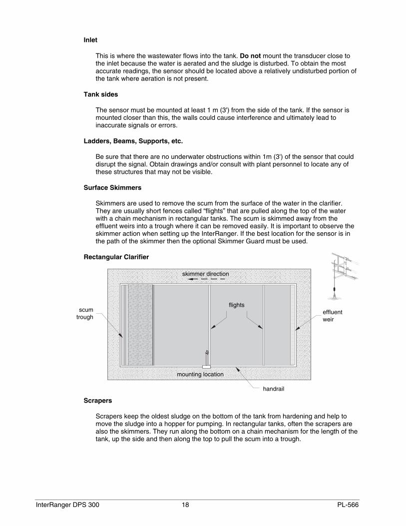
Skimmers are used to remove the scum from the surface of the water in the clarifier.They are usually short fences called “flights” that are pulled along the top of the waterwith a chain mechanism in rectangular tanks. The scum is skimmed away from theeffluent weirs into a trough where it can be removed easily. It is important to observe theskimmer action when setting up the InterRanger. If the best location for the sensor is inthe path of the skimmer then the optional Skimmer Guard must be used.
Rectangular Clarifier
Scrapers
Scrapers keep the oldest sludge on the bottom of the tank from hardening and help tomove the sludge into a hopper for pumping. In rectangular tanks, often the scrapers arealso the skimmers. They run along the bottom on a chain mechanism for the length of thetank, up the side and then along the top to pull the scum into a trough.
skimmer direction
mounting location
scumtrough
effluentweir
flights
handrail
PL-566 19 InterRanger DPS 300
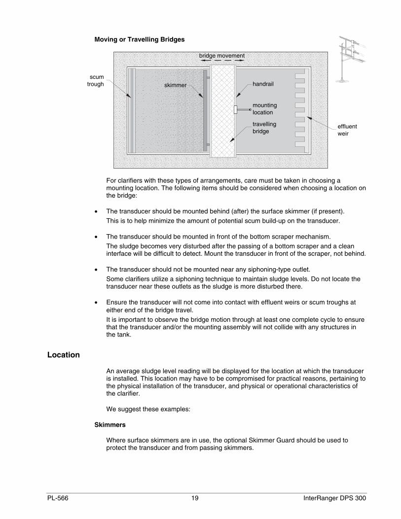
Moving or Travelling Bridges
For clarifiers with these types of arrangements, care must be taken in choosing amounting location. The following items should be considered when choosing a location onthe bridge:
• The transducer should be mounted behind (after) the surface skimmer (if present).
This is to help minimize the amount of potential scum build-up on the transducer.
• The transducer should be mounted in front of the bottom scraper mechanism.
The sludge becomes very disturbed after the passing of a bottom scraper and a cleaninterface will be difficult to detect. Mount the transducer in front of the scraper, not behind.
• The transducer should not be mounted near any siphoning-type outlet.
Some clarifiers utilize a siphoning technique to maintain sludge levels. Do not locate thetransducer near these outlets as the sludge is more disturbed there.
• Ensure the transducer will not come into contact with effluent weirs or scum troughs ateither end of the bridge travel.
It is important to observe the bridge motion through at least one complete cycle to ensurethat the transducer and/or the mounting assembly will not collide with any structures inthe tank.
Location
An average sludge level reading will be displayed for the location at which the transduceris installed. This location may have to be compromised for practical reasons, pertaining tothe physical installation of the transducer, and physical or operational characteristics ofthe clarifier.
We suggest these examples:
Skimmers
Where surface skimmers are in use, the optional Skimmer Guard should be used toprotect the transducer and from passing skimmers.
scumtrough
effluentweir
mountinglocation
bridge movement
handrail
travellingbridge
skimmer

InterRanger DPS 300 20 PL-566
If the Skimmer Guard is required, it can be field installed in a manner suitable for theclarifier installation and its surroundings. Consult with your mechanical department orcontractor.
The Mounting Assembly provides a method of installing the transducer or Skimmer Guardto clarifier handrails.
Mounting
As mentioned, mounting of the transducer must take into account several considerations.
• vertical adjustment of the transducer so that it is immersed in the clarifier water 3 to 6 cm.Milltronics Mounting Assembly provides this.
• horizontal adjustment of the transducer so that it can be extended away from the clarifierwall or handrailMilltronics Mounting Assembly provides this.
• articulation of the transducer conduit so that, where skimmers are in use, the transduceris deflected out of the way as the skimmer passes.Milltronics Skimmer Guard provides this.
PL-566 21 InterRanger DPS 300
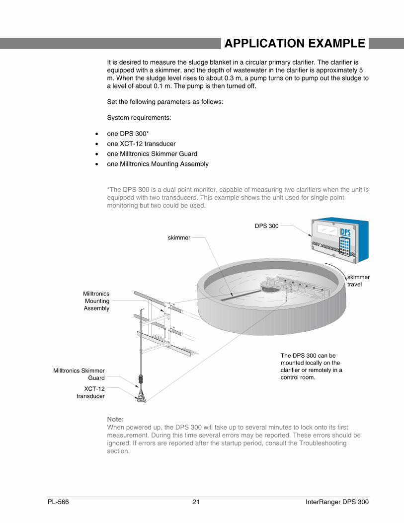
APPLICATION EXAMPLE It is desired to measure the sludge blanket in a circular primary clarifier. The clarifier isequipped with a skimmer, and the depth of wastewater in the clarifier is approximately 5m. When the sludge level rises to about 0.3 m, a pump turns on to pump out the sludge toa level of about 0.1 m. The pump is then turned off.
Set the following parameters as follows:
System requirements:
• one DPS 300*
• one XCT-12 transducer
• one Milltronics Skimmer Guard
• one Milltronics Mounting Assembly
*The DPS 300 is a dual point monitor, capable of measuring two clarifiers when the unit isequipped with two transducers. This example shows the unit used for single pointmonitoring but two could be used.
Note:When powered up, the DPS 300 will take up to several minutes to lock onto its firstmeasurement. During this time several errors may be reported. These errors should beignored. If errors are reported after the startup period, consult the Troubleshootingsection.
MilltronicsMountingAssembly
DPS 300
Milltronics SkimmerGuard
XCT-12 transducer
The DPS 300 can bemounted locally on theclarifier or remotely in acontrol room.
skimmertravel
skimmer

InterRanger DPS 300 22 PL-566
P001 = 1
sludge level measured from bottom (see P006)
P002 = 1
primary clarifier
P005 = 1
units in meters
P006 = 4.9,
distance from the faceof the transducer to thebottom of the clarifierdirectly beneath
P110, relay 1 = 1
relay 1 is assigned topoint 1
P111, relay 1 = 50,
relay 1 is assigned for pump control
P112, relay A setpoint = 0.3
sludge level at which the pump turns on
P113, relay B setpoint = 0.1
sludge level at which the pump turns off
P112 =0.3 m,pump on
P112 =0.1 m,pump off
P006 =4.9 m

PL-566 23 InterRanger DPS 300
INSTALLATION
Note:Installation shall only be performed by qualified personnel, and in accordance with localgoverning regulations.
Location
Electronics
Although the Mounting Assembly provides a mounting plate for external installation, theunit can also be installed indoors in a controlled environment comfortable to operatingpersonnel.
If it is required to mount the unit outdoors, the supplied panel can be attached to theMounting Assembly.
Regardless, the unit must be mounted in an area that:
• is conformant to the units specifications
• provides clearance to swing open the front cover and perform the required wiringconnections
• provides access for viewing
• is vibration free
Avoid a location that is:
• exposed to continuous direct sunlight. (Otherwise, provide a sun shield.)
• close to high voltage or current runs, contactors, or SCR control drives
Cable/Conduit Entry Requirements
Determine the number of conduit entries required:
• transducer(s) – one or two transducers
• communications – SmartLinx, RS-485, RS-232, bi-polar
• instrumentation – relay outputs, 4-20 mA
• synchronization – if more than one unit in proximity
• power
Note:• Transducer cables must be run in a grounded metal conduit, separate from other
wiring, (except TS-3 temperature sensor wiring, if applicable).• This product is susceptable to electrostatic shock. Follow proper grounding
procedures.

InterRanger DPS 300 24 PL-566
Transducer
As the transducer represents the point of measurement of the sludge blanket, it should belocated where it can give a reliable and meaningful measurement.
The ideal location may be compromised due to structural considerations of the clarifier,and practicality of installation. Refer to Application Planning on page 15 for moreinformation.
Optional Mounting Assembly
The mounting assembly provides an easy means of extending the transducer out into theclarifier wastewater by hanging off of nearby handrails.
826 mm(32.5”)
305 w x 292 h mm(12 w x 11. 5 h ”)
432 to610 mm(17–24”)
635 mm(25.7”)
101 mm (4”)
45 mm (1.75”)
152 mm(6”)
PL-566 25 InterRanger DPS 300
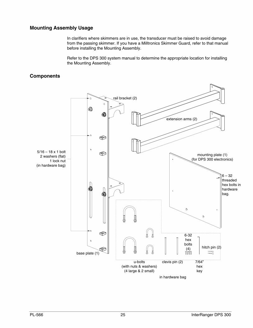
Mounting Assembly Usage
In clarifiers where skimmers are in use, the transducer must be raised to avoid damagefrom the passing skimmer. If you have a Milltronics Skimmer Guard, refer to that manualbefore installing the Mounting Assembly.
Refer to the DPS 300 system manual to determine the appropriate location for installingthe Mounting Assembly.
Components
extension arms (2)
mounting plate (1)(for DPS 300 electronics)
7/64”hexkey
base plate (1)
rail bracket (2)
u-bolts(with nuts & washers)
(4 large & 2 small)
hitch pin (2)
5/16 – 18 x 1 bolt2 washers (flat)
1 lock nut(in hardware bag)
6 – 32threadedhex bolts inhardwarebag.
6-32hexbolts(4)
clevis pin (2)
in hardware bag

InterRanger DPS 300 26 PL-566
Assembling the Mounting Assembly
1. Assemble the rail brackets, upper and lower, to the base plate
2. Assemble the extension arms, upper and lower, to the base plate by mating the arm andplate hinges and inserting the hinge pins.
3. Secure each hinge pin by inserting a hitch pin through the hole at the end of the pin.
4. (Optional) If it is required to mount the DPS 300 at the clarifier, then attach the mountingpanel to the base plate. Use the hex bolts provided to mount the DPS 300 to themounting panel. The DPS 300 is pre-drilled with the appropriate holes.
1.
1.
2.
2.
3.
4.

PL-566 27 InterRanger DPS 300
Mounting Assembly Installation
1. Attach the Mounting Assembly to the clarifier handrail by hanging the upper and lower railbrackets from the upper and lower rails.
2. The upper rail bracket is fixed. Check that the bolts are securely fastened.
3. Slide the lower rail bracket in position so that it rests on the lower rail. Tighten the slipbolts to secure the bracket.
4. Insert the four larger u-bolts through the upper and lower brackets, clamping the bracketsto the rails and fasten with the supplied washers and nuts.
2.
slip bolts
3.
4.
4.
1.
1.

InterRanger DPS 300 28 PL-566
Optional Skimmer Guard
The skimmer guard is designed for use with transducers applied to measurement ofsludge in wastewater clarifiers. The guard provides articulation of the mechanical andelectrical conduit connection to the transducer where skimmers are in use.
As the skimmer passes, it contacts the skimmer guard and pushes it up and over theskimmer; effectively clearing the transducer out of harm’s way. Once the skimmer haspassed, the guard is free to fall, re-immersing the transducer into the clarifier water.
The skimmer guard is available in two sizes:
• Type A – for skimmers 20 cm (8”) or less in cross-sectional height
• Type B – for skimmers 40 cm (16”) or greater in cross-sectional height
conduit coupling,¾” NPT or BSP
hinge
boot
transducer coupling,1” NPT or BSP
guard
Type A:500 mm (20”)
97 mm(3.8”)
100 mm(4”)
200 mm(8”)
Type B:890 mm (35”)

PL-566 29 InterRanger DPS 300
Transducer Assembly
1. Procure a length of corrosion resistant conduit for suspending the transducer and skimmer guardassembly such that the transducer face will be immersed 3 to 6 cm into the clarifier water. Milltronicssuggests ¾” standard stainless steel pipe (schedule 10) cut with ¾” NTP threads.
2. To facilitate running the transducer cable through the conduit, fish a wire through from the hinge end first.
3. Slide the 2-inch hose clamp over theknuckle of the Skimmer Guard.
4. Run the transducer cable through theskimmer guard; starting at thetransducer coupling, through theconduit and out the hinge.
5. Pull the cable through until thetransducer is pulled up to themounting coupling.
6. Screw the transducer into themounting coupling and tighten.
7. Run the transducer cable from the hinge out the conduitcoupling.
8. Pull cable taught insuring that the cable will notget pinched in the hinge.
9. Run the transducer cable through theboot and customer conduit.
10. Slide the boot over the end of the customerconduit, and screw the conduit into the coupling.
11. Slide the boot over the hinge.
The transducer and skimmer guard are now ready for installation.
Location and Installation
If a Mounting Assembly is used …
If a Milltronics mounting assembly is being used to mount the Skimmer Guard assembly,first refer to Optional Mounting Assembly on page 24.
For Location
For recommendations as to the preferred point of installation of the transducer andskimmer guard, refer to Application Planning on page 15.
customer conduit
boot
skimmer guard
transducer
2” hose clamp
1” hose clamp
2” bushing
InterRanger DPS 300 30 PL-566
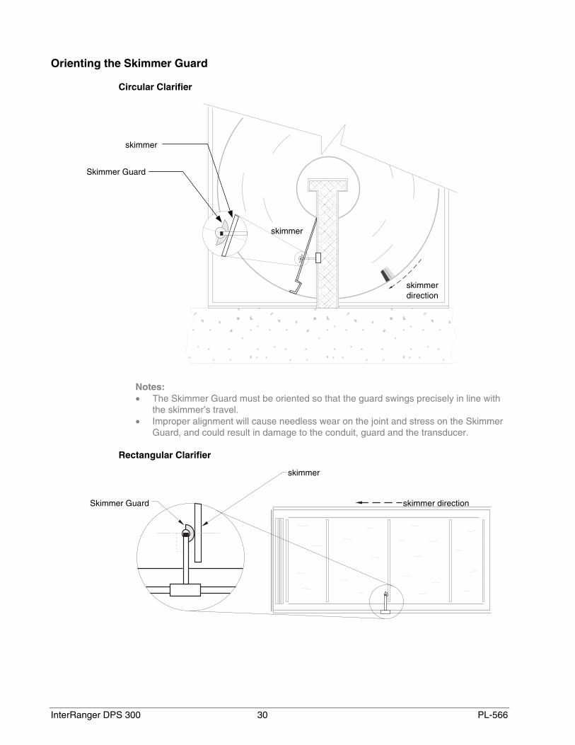
Orienting the Skimmer Guard
Circular Clarifier
Notes:• The Skimmer Guard must be oriented so that the guard swings precisely in line with
the skimmer’s travel.• Improper alignment will cause needless wear on the joint and stress on the Skimmer
Guard, and could result in damage to the conduit, guard and the transducer.
Rectangular Clarifier
skimmer direction
skimmer
Skimmer Guard
Skimmer Guard
skimmer
skimmer
skimmerdirection

PL-566 31 InterRanger DPS 300
Operation
As the skimmer passes, it contacts the skimmer guard and pushes it up and over theskimmer; effectively clearing the transducer out of harm’s way. Once the skimmer haspassed, the guard is free to fall, re-immersing the transducer into the clarifier water.
Note:Before leaving, run the skimmer to insure that the skimmer guard is operating properly.
skimmer direction

InterRanger DPS 300 32 PL-566
Transducer Mounting
Procure a length of corrosion resistant conduit for suspending the transducer* such thatthe transducer face will be immersed 3 to 6 cm into the clarifier. Milltronics suggests ¾”standard stainless steel pipe (schedule 10) cut with ¾” NTP threads.
* transducer or transducer and skimmer guard assembly. Refer to the Skimmer Guardinstructions (above).
Note:If skimmer is in operation, shut off until mounting is complete
With the extension arms swung in towards the rail, clamp the conduit extension of thetransducer assembly to the extension arm ends and snug tight using the two smaller u-bolts. Slide the conduit down so that the transducer face is immersed 3 to 6 cm into theclarifier water.
Note:Run the transducer cable from the rigid conduit end, through a flexible conduit to thejunction box (if required) in a manner that allows the extension arm to swing out fully.
3 to 6 cm

PL-566 33 InterRanger DPS 300
Extending the Arms
Swing the extension arms (and transducer assembly) out 90 degrees into the clarifier andbolt the extension arm hinges to the chassis using the supplied washers and nuts.
Before Leaving
If a Milltronics Skimmer Guard is used, insure that is has been properly oriented in linewith the skimmer’s travel. Refer to the Skimmer Guard instructions.
Insure that the conduit clamping u-bolts are sufficiently tight to hold the conduit fixed.
Start the skimmer and let it pass by the Skimmer Guard (if used) to ensure thateverything is well-positioned. See Orienting the Skimmer Guard on page 30 for moredetails. Make any necessary adjustments and tighten the 1” u-bolts securely. Finally, boltthe extension arms to the base plate.

InterRanger DPS 300 34 PL-566
Assembly
Mounting - Electronics
Note:Non-metallic enclosure does not provide grounding between connections. Use groundingtype bushings and jumpers.
285 mm(11.2”)
209 mm(8.2”)
267 mm(10.5”)
106 mm(4.2”)
Suitable location for conduit entrances.Use water tight conduit hubs to maintain the enclosure rating.
mounting hole, 4.3 mm (0.17”) diameter,access under lid (4 places).
172 mm(6.8”)
lid screw(6 places)
programmer
lid(hinged) customer
mounting screws

PL-566 35 InterRanger DPS 300
Interconnection
Before interconnecting system components to the DPS 300 terminals, verify that allcomponents have been installed in accordance with the associated product instructionmanuals.
Connect all associated equipment cable shields to the DPS 300 shield connections. toavoid ground loops, ground shields only at one end. Insulate shields at junctions toprevent ground loops.
Warning:
• All field wiring must have insulation suitable for at least 250V.• Hazardous voltage present on transducer terminals during operation• Relay contact terminals are for use with equipment having no accessible live parts
and wiring having insulation suitable for at least 250V.
voltageselect
communicationmode LED
displayscope
connections
optionalSmartLinx
module EPROMboard A
board Bterminal block
InterRanger DPS 300 36 PL-566
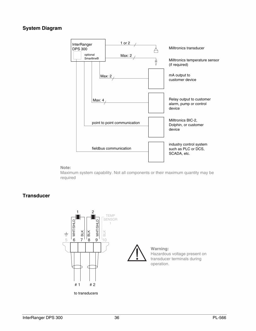
System Diagram
Note:Maximum system capability. Not all components or their maximum quantity may berequired
Transducer
Warning:Hazardous voltage present ontransducer terminals duringoperation.
to transducers
InterRangerDPS 300
fieldbus communication
point to point communication
Milltronics transducer
Milltronics temperature sensor(if required)
Milltronics BIC-2,Dolphin, or customerdevice
Relay output to customeralarm, pump or controldevice
industry control systemsuch as PLC or DCS,SCADA, etc.
mA output tocustomer device
1 or 2
Max: 2
Max: 2
Max: 4
optionalSmartlinx®

PL-566 37 InterRanger DPS 300
Temperature Sensor (if required)
Notes:• Use TS-3 temperature sensors only. Don't jumper
the terminals if TS-3's are not used.• Maximum cable run to TS-3 is 365m (1200ft) using
18 AWG, 2 wire twisted/shielded.
Relays
All relays are certified for usein equipment where the shortcircuit capacity of the circuits inwhich they are connected islimited by fuses having ratingsnot exceeding the rating of therelays.
Note:Relays are shown in de-energized state.
mA Outputs
To customer’s equipment
0/4—20mA isolated output to 750Ω max

InterRanger DPS 300 38 PL-566
Communication
NoteThe communication protocol is automatically detected by the DPS 300 and shown viaLED on the motherboard.
Serial: RS-232 RS-485
Bipolar Current
Connect the Milltronics BIC-II (if required) to the Peripheral Communications terminals asbelow.
SmartLinx
Refer to the appropriate SmartLinx manual for installation and wiring information.
to customer device,RS-232 port
15m (50 ft) max
to customer device,RS-485 port
1200m (4,000 ft) max
Ground shield atone end only.
Beldon 8760 (or equivalent), 18AWG, 2 wire, shielded/twisted,
1500 (5000 ft) max.
refer to BIC-II instruction manual
to RS-232 or RS-422 hostdevice, 15 m (50 ft), or 1200m(4,000 ft) max respectively.
01/22/99
PL-566 39 InterRanger DPS 300
Level System Synchronization
Avoid mounting the DPS 300 near another ultrasonic level monitor. Likewise, when morethan one monitor is installed within a single plant/facility, ensure the transducer cables ofeach system are run in separate grounded metal conduits. If this system separation isimpractical, or despite separation efforts measurement difficulties are encountered,system synchronization may be required.
Note:To synchronize the DPS 300 with other Milltronics ultrasonic level monitors contactMilltronics or your local distributor.
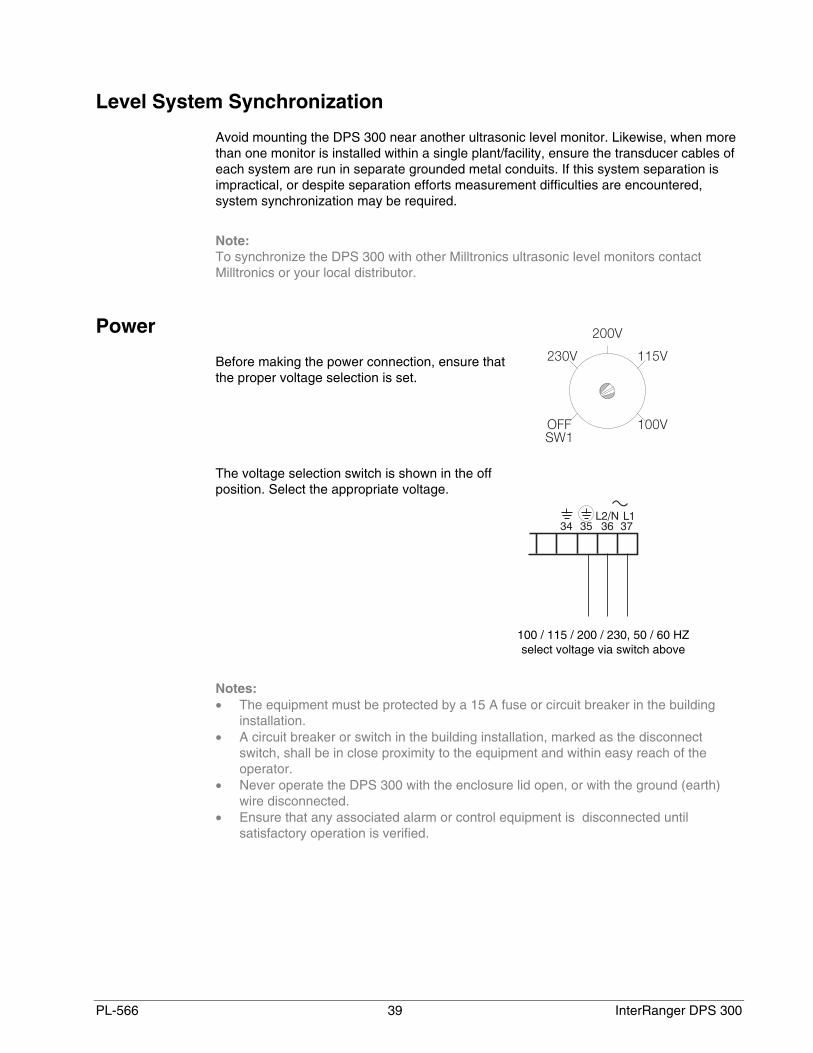
Power
Before making the power connection, ensure thatthe proper voltage selection is set.
The voltage selection switch is shown in the offposition. Select the appropriate voltage.
Notes:• The equipment must be protected by a 15 A fuse or circuit breaker in the building
installation.• A circuit breaker or switch in the building installation, marked as the disconnect
switch, shall be in close proximity to the equipment and within easy reach of theoperator.
• Never operate the DPS 300 with the enclosure lid open, or with the ground (earth)wire disconnected.
• Ensure that any associated alarm or control equipment is disconnected untilsatisfactory operation is verified.
100 / 115 / 200 / 230, 50 / 60 HZselect voltage via switch above

InterRanger DPS 300 40 PL-566
Programmer
The hand programmer fits into the docking bay and is kept there with a magnet. Use thehand programmer to change individual parameters.
Dolphin ComVerter
The ComVerter fits into the docking bay similarly to the hand programmer and providescommunications with a PC running Dolphin Plus (available separately).

PL-566 41 InterRanger DPS 300
PROGRAMMING Operator programmable features are identified by a Point Number and ParameterNumber. The Point Number refers to the Transducer (clarifier) Number, Relay Number, ormA Output Number as identified by the Point Type indicators. Parameter Numbers havea preset Parameter Value for each Point Number.
Programming is accomplished by altering the preset Parameter Values as required toobtain the RUN mode operation desired. All operator programmable features are definedin the Quick Start Parameters, Application Parameters, and Enhancement Parameterssections of this instruction manual.
Display
In the program mode, the Point Type, Point Number, Parameter Number, and ParameterValue (as well as a variety of other programming information) may be viewed.
Note that many indicators are specific to certain programming conditions and therefore,not all indicators are displayed at any given time.
Parameter Number the programmable feature the Parameter Value pertains to.Point Type the Point Number refers to a Transducer, Relay, mA Output, or TS-3.Point Number the Transducer, Relay, mA Output or TS-3 # the Parameter Value
pertains to.Parameter Value the current value of the Parameter Number for the Point Number
displayed.Percent indicates the Parameter Value is displayed in percent.Invalid Entry indicates the value entered is questionable (are you sure?).Auxiliary Function indicates Auxiliary Function access (applies to only some Parameter
Numbers).Scroll Access Tag indicates the Parameter Value may be scroll accessed.Program Mode indicates the program mode is accessed.
pointtype
pointnumber
parametervalue units
auxiliaryfunction
scrollaccess tag
invalidentry
parameternumber
programmode
relay inservice
transducer
relay
analog output
TS-3
index

InterRanger DPS 300 42 PL-566
Keypad – Program Mode
In the program mode, use the DPS 300 programmer keys to perform the identifiedfunctions.
shift access to Point Number, Parameter Number, or Parameter Value display.
— input the numeric value into the accessed display.
input a Parameter Value decimal point (moves Profile and TVT Pointers left).
input a negative Parameter Value (moves Profile and TVT Pointers right).
delete the current Parameter Value display (initiate a parameter reset).
store the current Parameter Value in memory (complete a parameter reset).
switch the Parameter Value to % or Units (access Auxiliary Parameter Function).
increase the accessed display value.
decrease the accessed display value.
take an ultrasonic measurement.
enter the RUN mode.
numeric value keys
function keys
PL-566 43 InterRanger DPS 300
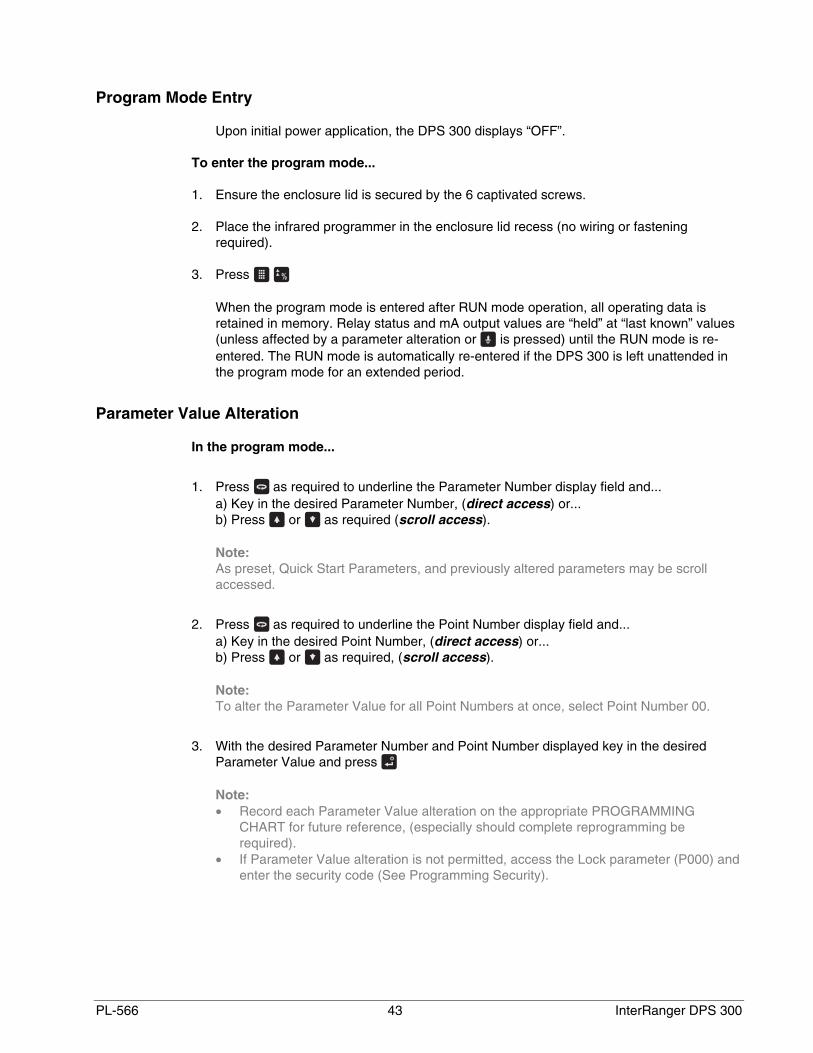
Program Mode Entry
Upon initial power application, the DPS 300 displays “OFF”.
To enter the program mode...
1. Ensure the enclosure lid is secured by the 6 captivated screws.
2. Place the infrared programmer in the enclosure lid recess (no wiring or fasteningrequired).
3. Press
When the program mode is entered after RUN mode operation, all operating data isretained in memory. Relay status and mA output values are “held” at “last known” values(unless affected by a parameter alteration or is pressed) until the RUN mode is re-entered. The RUN mode is automatically re-entered if the DPS 300 is left unattended inthe program mode for an extended period.
Parameter Value Alteration
In the program mode...
1. Press as required to underline the Parameter Number display field and...a) Key in the desired Parameter Number, (direct access) or...b) Press or as required (scroll access).
Note:As preset, Quick Start Parameters, and previously altered parameters may be scrollaccessed.
2. Press as required to underline the Point Number display field and...a) Key in the desired Point Number, (direct access) or...b) Press or as required, (scroll access).
Note:To alter the Parameter Value for all Point Numbers at once, select Point Number 00.
3. With the desired Parameter Number and Point Number displayed key in the desiredParameter Value and press
Note:• Record each Parameter Value alteration on the appropriate PROGRAMMING
CHART for future reference, (especially should complete reprogramming berequired).
• If Parameter Value alteration is not permitted, access the Lock parameter (P000) andenter the security code (See Programming Security).

InterRanger DPS 300 44 PL-566
Parameter Reset Features
On initial power up, all parameters are at “original” values. In many cases, when aParameter Value is altered, associated Parameter Values are automatically alteredaccordingly. When a Parameter Number is accessed, if the preset Parameter Valuedisplayed is acceptable, no entry is required.
To return an operator adjusted Parameter Value to the preset value, with the appropriatePoint Number and Parameter Number displayed press
To reset numerous parameters to preset values, refer to Master Reset (P999).
Note:Perform a Master Reset (P999) if the DPS 300 was “bench tested” using arbitraryParameter Values before system installation, following an EPROM replacement, orwhenever complete reprogramming is required.
Special Parameters
Some Parameter Values are for display purposes only and cannot be operator altered.These are referred to as view only parameters. In the parameters sections of thisinstruction manual, View Only parameters are identified by a “(V)” beside the ParameterNumber.
Some Parameter Values must be common for all Point Numbers. These are referred toas global parameters. When a global parameter is accessed, the Point Number displayautomatically switches to Point Number 00, and returns to the Point Number previouslyselected when a non-global parameter is accessed. In the parameters sections of thismanual, Global parameters are identified by a “(G)” beside the Parameter Number.
Programming SecurityAll operator programming is retained in non-volatile memory, immune to powerinterruptions. When programming is complete, the programmer may be removed andlocked away to prevent inadvertent programming alteration. As well the Lock (P000)parameter may be used.
Security Parameter: P000 (G) Lock
Use this feature (if desired) to secure all programming from inadvertent alteration.
“Direct access” this parameter (it cannot be scroll accessed) after all programming iscomplete and enter any value (other than 1954) to activate the programming Lock.
When Lock is activated, the DPS 300 may be switched from the RUN mode to theprogram mode and the value of any parameter may be viewed but not altered. To unlock,access this parameter and enter the value “1954”.
This parameter cannot be reset by pressing .
Values:
1954 = off (Parameter Value alteration permitted) 1 = control relays active during simulationother = activated (programming secured)
PL-566 45 InterRanger DPS 300
QUICK START PARAMETERS Alter the Quick Start Parameters as required to suit the installation requirements.
Refer to the Application Example for assistance, if required.
Note:When powered up, the DPS 300 will take up to five minutes to lock onto its firstmeasurement. During this time several errors may be reported. These errors should beignored. If errors are reported after the five-minute startup period, consult theTroubleshooting section.
P001 Operation
Enter the type of RUN mode operation desired.
Select:
“level”, display Empty (P006) to sludge level distance.“space”, display Span (P007) to sludge level distance.“distance”, display transducer face to sludge level distance.“out-of-service” the transducer is not scanned, alarm relay(s) energize, pump relay(s)
de-energize, and mA output(s) go to the Empty value.Values:
0 = out-of-service1 = level (preset)2 = space3 = distance
P002 Material
Enter a value for the type of clarifier being monitored.
The DPS 300 will detect the sludge interface in a variety of applications. Select theappropriate value from the list below for the DPS 300 mounting and clarifier type thatmost closely matches your application.
Note:Several other parameter values are preset by P002. See DEFAULT PARAMETERSETTINGS on page 111 for a complete list.
Demonstration
0 = For demonstration purposes in air only.
Primary Wastewater Clarifiers
1 = Stationary mounting with surface skimmers and bottom scrapers (preset).2 = Stationary mounting with bottom scrapers only.3 = Rectangular clarifier with travelling bridge arrangement.4 = Circular clarifier with rotating bridge arrangement.

InterRanger DPS 300 46 PL-566
Secondary Wastewater Clarifiers
5 = Stationary mounting with surface skimmers and bottom scrapers.6 = Stationary mounting with bottom scrapers only.7 = Stationary mounting without surface skimmers or bottom scrapers.8 = Rectangular clarifier with travelling bridge arrangement.9 = Circular clarifier with rotating bridge arrangement.
Potable Water Clarifiers
10 = Stationary mounting with bottom scrapers only.11 = Stationary mounting without skimmers or scrapers.12 = Rectangular clarifier with travelling bridge arrangement.13 = Circular clarifier with rotating bridge arrangement.
Mining Clarifiers
14 = Stationary mounting with bottom scrapers only.15 = Stationary mounting with surface skimmers and bottom scrapers.
Settling Tanks
16 = Stationary mounting without skimmers or bottom scrapers(suspended solids >1%)
17 = Stationary mounting without skimmers or bottom scrapers(suspended solids <1%)
P005 (G) Units
Enter the units of measure desired for programming Empty (P006) and Span (P007).
Values:
1 = meters (m) (preset)2 = centimeters (cm)3 = millimeters (mm)4 = feet (ft)5 = inches (in)
P006 Empty
Enter the maximum distance (transducer face to clarifier bottom) to be measured, inUnits.
This value is preset to 4.000 m or equivalent Units (P005).
The value entered automatically sets Span (P007) to the maximum recommended value.
Values: 0.000 to 9999

PL-566 47 InterRanger DPS 300
P007 Span
Enter the maximum surface distance from Empty (P006).
Span is automatically preset to 3.000 m or equivalent Units (P005).
Values: 0.000 to 9999
Note:With the Quick Start Parameters altered as required, proceed to OPERATION to identify /verify basic system performance.
Empty(P006)
Span(P007)
XCT –12 transducer
wastewater
sludge
maximum height ofsludge blanket

InterRanger DPS 300 48 PL-566
PL-566 49 InterRanger DPS 300
OPERATION With Quick Start parameter alteration complete, the DPS 300 may be put into operation.(If APPLICATION or ENHANCEMENT PARAMETERS are altered, OPERATION isaltered accordingly from that indicated).
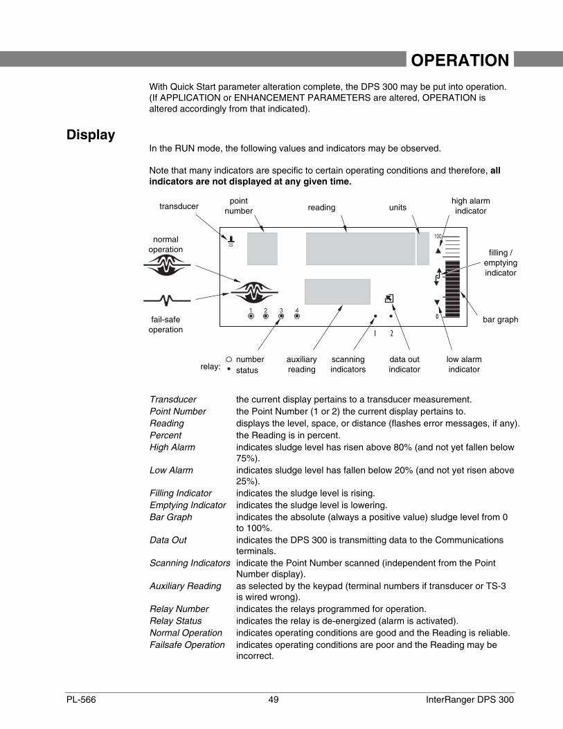
DisplayIn the RUN mode, the following values and indicators may be observed.
Note that many indicators are specific to certain operating conditions and therefore, allindicators are not displayed at any given time.
Transducer the current display pertains to a transducer measurement.Point Number the Point Number (1 or 2) the current display pertains to.Reading displays the level, space, or distance (flashes error messages, if any).Percent the Reading is in percent.High Alarm indicates sludge level has risen above 80% (and not yet fallen below
75%).Low Alarm indicates sludge level has fallen below 20% (and not yet risen above
25%).Filling Indicator indicates the sludge level is rising.Emptying Indicator indicates the sludge level is lowering.Bar Graph indicates the absolute (always a positive value) sludge level from 0
to 100%.Data Out indicates the DPS 300 is transmitting data to the Communications
terminals.Scanning Indicators indicate the Point Number scanned (independent from the Point
Number display).Auxiliary Reading as selected by the keypad (terminal numbers if transducer or TS-3
is wired wrong).Relay Number indicates the relays programmed for operation.Relay Status indicates the relay is de-energized (alarm is activated).Normal Operation indicates operating conditions are good and the Reading is reliable.Failsafe Operation indicates operating conditions are poor and the Reading may be
incorrect.
transducerpoint
number reading unitshigh alarmindicator
filling /emptyingindicator
bar graph
low alarmindicator
data outindicator
scanningindicators
auxiliaryreading
number
fail-safeoperation
normaloperation
statusrelay:

InterRanger DPS 300 50 PL-566
Keypad – Run Mode
In the RUN mode, the following programmer keys perform the identified functions.
selects the Auxiliary Reading “mA output value for the Point Number displayed”.
selects the Auxiliary Reading “clarifier wastewater temperature”.
selects the Auxiliary Reading “rate of sludge level change”.
selects the Auxiliary Reading “failsafe time left” (in percent).
selects the Auxiliary Reading “parameter value” (Key in any Parameter Number).
selects the Auxiliary Reading “sludge level” (may be operator altered via P731).
selects the Auxiliary Reading “distance” (sludge level to transducer face).
initiates program mode access (see ).
switches the Reading between “Units/percent of Span” (completes program modeaccess).
stops/starts the Point Number auto display scroll.
selects the next Point Number (when auto display scroll is stopped).
selects the previous Point Number (when auto display scroll is stopped).
auxiliary readingkeys
function keys

PL-566 51 InterRanger DPS 300
System Performance Evaluation
For initial RUN mode entry (or after any programming alteration), do not use the DPS 300to operate process control equipment until satisfactory system programming andperformance is verified.
1. Press to enter the RUN mode.
“----” may be displayed briefly while the DPS 300 takes measurements and calculates theReading.
If an alarm symbol is displayed, the corresponding relay is de-energized.
POINT # ALARM INDICATOR RELAY #1 High Alarm 11 Low Alarm 22 High Alarm 32 Low Alarm 4
2. Press to display Readings in % (percent of Span, P007) based upon Operation(P001).
OPERATION LEVEL SPACE, or DISTANCE*Empty to Full = 0 to 100% 100 to 0%
* Objects close to the transducer face (0%) are not detectable.
3. Press to observe the mA output value for the Point Number displayed (AuxiliaryReading).
OPERATION LEVEL SPACE, or DISTANCE*Empty to Full = 4-20 mA 20-4 mA
* Objects close to the transducer face (4 mA) are not detectable.
4. Press to observe the Failsafe Time Left (time left in percent before failsafe activation).
Each time a valid measurement is made for the Point Number displayed, this value(Auxiliary Reading) is reset to 100 and begins to fall toward 0 until the next validmeasurement is made.
If the Failsafe Time Left reaches 0, the DPS 300 flashes “LOE” in the Reading display.
All associated data is supplied to the Peripheral Communications terminals (27 and 28). Ifa BIC-II is connected, refer to TECHNICAL REFERENCE / Communication Support formessage format and protocol information.

InterRanger DPS 300 52 PL-566
Performance Test Results
Monitor system performance carefully, under all anticipated operating conditions.
A. If the DPS 300 performs exactly as required, copy all Parameter Value alterations to thePROGRAMMING CHARTS in the back of this instruction manual. (Altered ParameterValues may be scroll accessed). No further action is required.
B. If a measurement difficulty is encountered (the “LOE” display persists after start up), orperformance does not meet installation requirements, proceed to theTROUBLESHOOTING GUIDE.
C. If the DPS 300 provides accurate and repeatable measurements, however alternateReading units, failsafe action, relay, or mA output operation is desired, proceed toAPPLICATION PARAMETERS.
If all operating conditions cannot be observed during the System PerformanceEvaluation, refer to ENHANCEMENT PARAMETERS / Reading Measurement (P920).Perform a Reading Measurement simulation to verify programming.
Ensure the PROGRAMMING CHARTS are altered accordingly, and a new SystemPerformance Evaluation is conducted, following any operation alteration or measurementdifficulty remedy.
Note:Connect (or enable) process control / alarm equipment to the DPS 300 only aftersatisfactory performance is verified for all possible operating conditions.

PL-566 53 InterRanger DPS 300
APPLICATION PARAMETERS This section identifies the DPS 300 operator programmable features which may be usedto modify the DPS 300 display, failsafe, relay, and/or mA output operation.
Volume Parameters (P050 to P055)
If Readings proportional to volume are desired, adjust the following parameters
P050 Tank Shape
Enter the shape option that matches the clarifier monitored.
If the shape option selected, requires additional clarifier dimension entry, the associatedparameters (as indicated below) may be scroll accessed.
When Operation is “level” (P001 = 1), sludge volume is calculated. Alternatively, whenOperation is “space” (P001 = 2), remaining volume capacity is calculated.
In the RUN mode, Readings are displayed in percent of ( and mA outputs areproportional to) maximum volume. to convert Readings to volumetric units, see MaxVolume (P051).
Values: 0 = volume calculation not required (preset)
flat bottom spherical bottom (P052)
conic or pyramidal bottom sloped bottom (P052) universal linear (P054 /P055)
parabolic bottom flat end universal curved (P054 /P055)
parabolic ends (P052 /P053)
or
or
or
A
A
A L
1 =
2 =
3 =
4 =
5 =
6 =
7 =
9 =
10 =
A
A
InterRanger DPS 300 54 PL-566
P051 Max Volume
Use this feature to display the Reading in volumetric units rather than percent.
Enter the clarifier volume between Empty (P006) and Span (P007).
e.g. 1 If the volume = 3650 m3, enter 3650.
e.g. 2 If the volume = 267,500 US gallons, enter 267.5 (1000's of gallons).
Values: 0.000 to 9999
P052 Clarifier Dimension A
Enter the height as depicted if P050 = 2,3,4, or 5, or the length of one end if P050 = 7, inUnits (P005).
Values: 0.000 to 9999
P053 Clarifier Dimension L
Enter the length as depicted (excluding both end sections) if P050 = 7, in Units (P005).
Values: 0.000 to 9999
P054 Level Breakpoints (Universal Volume Calculation)
Enter level breakpoints* (here volume is known) if P050 = 9 or 10.
Values: 0.000 to 9999
P055 Breakpoint Volumes ( Universal Volume Calculation )
Enter the volume* corresponding to each Level Breakpoint entered.
Values: 0.000 to 9999
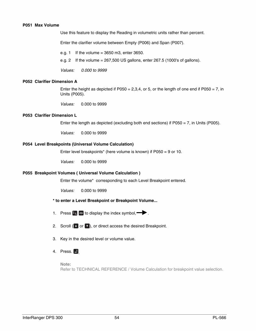
* to enter a Level Breakpoint or Breakpoint Volume...
1. Press to display the index symbol, .
2. Scroll ( or ), or direct access the desired Breakpoint.
3. Key in the desired level or volume value.
4. Press. .
Note:Refer to TECHNICAL REFERENCE / Volume Calculation for breakpoint value selection.
PL-566 55 InterRanger DPS 300
Reading Parameters (P060 to P062)
If Reading alteration is required, alter the following parameters to:
• alter the number of decimal places displayed.
• convert to units other than Units (P005), % of Span (P007), or Max Volume (P051).
• reference measurements to some point other than Empty (P006) or Span (P007).
Note:If alteration is not required, proceed to FAILSAFE PARAMETERS.
P060 Decimal Position
Enter the maximum number of decimal places to be displayed in the Reading.
In the RUN mode, the number of decimal places displayed is automatically adjusted (ifnecessary) to prevent the number of Reading digits from exceeding display capabilities.
This value is automatically altered when Units (P005) or Max Volume (P051) are altered.
Values:
0 = no digits after the decimal point1 = 1 digit after the decimal point2 = 2 digits after the decimal point3 = 3 digits after the decimal point
P061 Convert Reading
Enter the value to multiply the Reading by, (before display).
This feature is preset to 1.000 (no conversion).
e.g. If the Reading is currently displayed in feet, to display in yards, enter 3.
Note:Avoid entering a value that, when multiplied by the maximum current Reading, couldexceed 5 digits before the Decimal Position.
Values: -999 to 9999
P062 Offset Reading
Enter the value to be added to the Reading, (before display).
This feature is preset to 0.000, (no offset).
This feature affects the DPS 300. Reading only. (Relays and mA outputs are notaffected).
Values: -999 to 9999
InterRanger DPS 300 56 PL-566
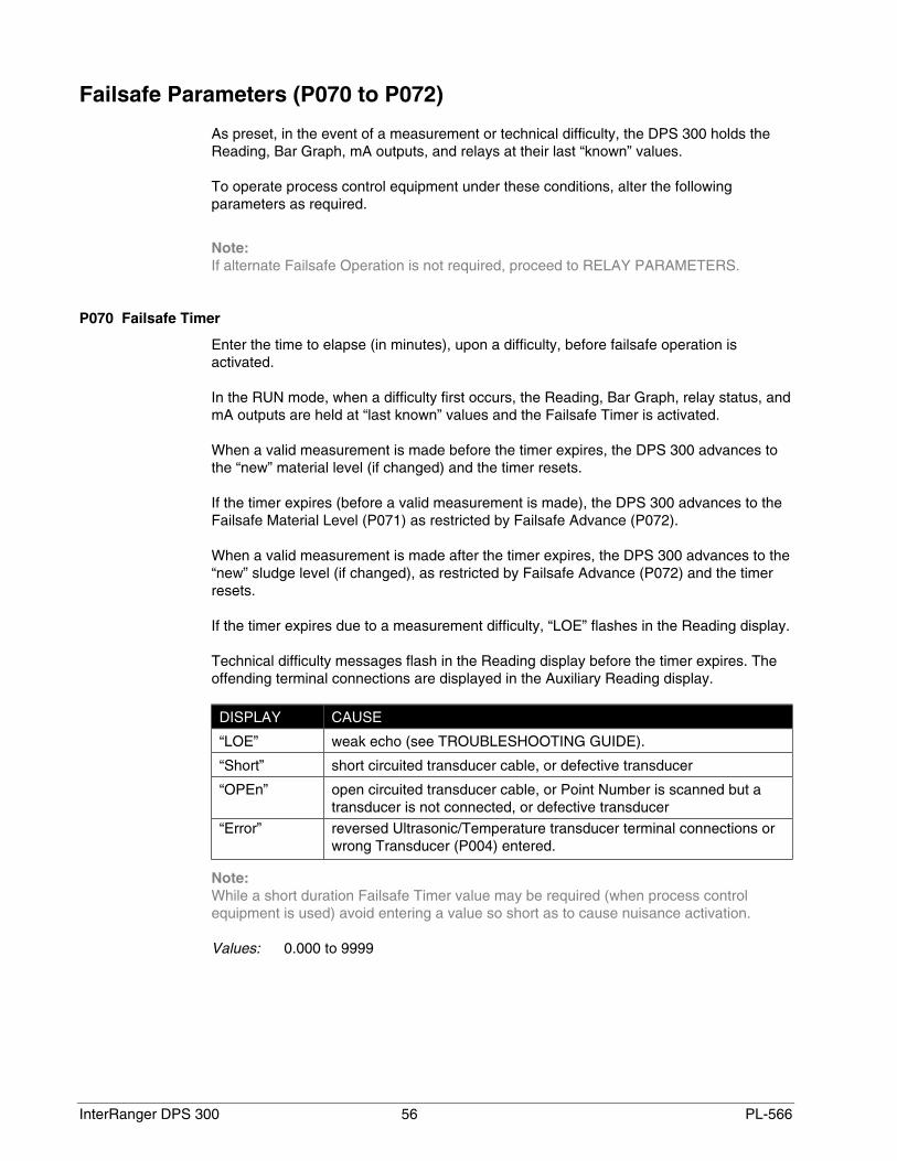
Failsafe Parameters (P070 to P072)
As preset, in the event of a measurement or technical difficulty, the DPS 300 holds theReading, Bar Graph, mA outputs, and relays at their last “known” values.
To operate process control equipment under these conditions, alter the followingparameters as required.
Note:If alternate Failsafe Operation is not required, proceed to RELAY PARAMETERS.
P070 Failsafe Timer
Enter the time to elapse (in minutes), upon a difficulty, before failsafe operation isactivated.
In the RUN mode, when a difficulty first occurs, the Reading, Bar Graph, relay status, andmA outputs are held at “last known” values and the Failsafe Timer is activated.
When a valid measurement is made before the timer expires, the DPS 300 advances tothe “new” material level (if changed) and the timer resets.
If the timer expires (before a valid measurement is made), the DPS 300 advances to theFailsafe Material Level (P071) as restricted by Failsafe Advance (P072).
When a valid measurement is made after the timer expires, the DPS 300 advances to the“new” sludge level (if changed), as restricted by Failsafe Advance (P072) and the timerresets.
If the timer expires due to a measurement difficulty, “LOE” flashes in the Reading display.
Technical difficulty messages flash in the Reading display before the timer expires. Theoffending terminal connections are displayed in the Auxiliary Reading display.
DISPLAY CAUSE
“LOE” weak echo (see TROUBLESHOOTING GUIDE).
“Short” short circuited transducer cable, or defective transducer
“OPEn” open circuited transducer cable, or Point Number is scanned but atransducer is not connected, or defective transducer
“Error” reversed Ultrasonic/Temperature transducer terminal connections orwrong Transducer (P004) entered.
Note:While a short duration Failsafe Timer value may be required (when process controlequipment is used) avoid entering a value so short as to cause nuisance activation.
Values: 0.000 to 9999

PL-566 57 InterRanger DPS 300
P071 Failsafe Material Level
Select the material level to be reported when the Failsafe Timer expires.
If “HOLd” (preset) is selected, in the RUN mode, the “last known” sludge level is held.
If “HIGH” or “LOW” are selected, the DPS 300 advances to the Span (P007) level orEmpty (P006) level as restricted by Failsafe Level Advance.
Select the Failsafe Material Level based upon the relay and/or mA output operationrequired during failsafe operation.
e.g.1 To de-energize a high alarm relay select “HIGH”.
e.g.2 To force an “empty level” mA output (perhaps to have pumps stopped), select“LOW”.
To select HIGH, LOW, or HOLd...
1. Press to display the Auxiliary Function symbol,
2. Press or as required to scroll access the desired option,
3. Press .
Alternatively, a specific Failsafe Material Level within -50 to 150% of Span (P007) may beentered directly in Units (P005), or % of Span (P007).
Values: -999 to 9999
P072 Failsafe Level Advance
Select the restriction applied to the DPS 300 advance to (and from) the Failsafe MaterialLevel.
When “restricted” (preset), the DPS 300 advances to the Failsafe Material Level (and tothe “new” material level when a valid measurement is made) at the Max Fill/Empty Rate(P700/P701) to a maximum of 0.1 m/min
Alternatively, when “immediate” is selected, the Failsafe Material Level (or “new” materiallevel) is assumed immediately.
Otherwise, when “fast back” is selected, the Failsafe Level Advance is restricted,however the advance to the new material level (when a valid measurement is made) isimmediate.
Values:
1 = restricted2 = immediate3 = fast back

InterRanger DPS 300 58 PL-566
Relay Parameters (P100 to P104, P110 to P113, P129)
If relays are to be used, alter the following parameters as required.
Note:Otherwise, proceed to mA OUTPUT PARAMETERS.
Relays may be programmed as Standard Alarms or for Custom Relay operation.
For Standard Alarms (relays operate based on sludge level), select the Relay Set Up(P100) desired and alter the Standard Alarm (P101 to P104) parameters as required,before proceeding to Relay Failsafe (P129).
For Custom Relay operation, select the Relay Set Up (P100) which most closely matchesyour requirements, and alter the Custom Relay Parameters (P110 to P113) as required,before proceeding to Relay Failsafe.
P100 (G) Relay Set Up
This parameter presets relays to operate as Standard Alarms. The Relay Allocation(relay / point number association) and Standard Alarm (P101 to P104) parameters arealso preset.
Relay status during a measurement difficulty is dependent upon Failsafe programming.See Failsafe Parameters (P070 to P072) and Relay Failsafe (P129). As preset, relaystatus is “held” at “last known” sludge levels until a valid measurement is made.
Option Relay # Point # Standard Alarm (as % of Span, P007)
1 1 1 (High Alarm) P101 = 80.00%
2 1 (Low Alarm) P102 = 20.00%
3 2 (High Alarm) P101 = 80.00%
4 2 (Low Alarm) P102 = 20.00%
2 1 1 (High Alarm) P101 = 80.00%
2 1 (High High Alarm) P103 = 90.00%
3 2 (High Alarm) P101 = 80.00%
4 2 (High High Alarm) P104 = 10.00%
3 1 1 (Low Alarm) P102 = 20.00%
2 1 (Low Low Alarm) P104 = 10.00%
3 2 (Low Alarm) P102 = 20.00%
4 2 (Low Low Alarm) P104 = 10.00%
4 1 1 (High Alarm) P101 = 80.00%
2 1 (Low Alarm) P102 = 20.00%
3 1 (High High Alarm) P103 = 90.00%
4 1 (Low Low Alarm) P104 = 10.00%

PL-566 59 InterRanger DPS 300
Independently altered Standard Alarms (P101 to P104), Relay Allocation (P110), RelayFunction (P111) and Relay A/B Setpoints (P112/P113) are automatically reset when aRelay Set Up value is altered.
Values:
1 = Set Up 12 = Set Up 23 = Set Up 34 = Set Up 4
Standard Alarms (P101 to P104)
In the RUN mode, when the sludge level...
• rises to a High or High High Alarm value, the associated Alarm and Relay Statusindicators are displayed and the allocated relay(s) de-energize.
• falls 5% of Span (P007) below the High or High High Alarm value, the associated Alarmand Relay Status indicators extinguish, and the allocated relay(s) energize.
• falls below the Low or Low Low Alarm value, the associated Alarm and Relay Statusindicators are displayed and the allocated relay(s) de-energize.
• rises 5% of Span (P007) above the Low and Low Low Alarm value, the associated Alarmand Relay Status indicators extinguish, and the allocated relay(s) energize.
Note:Enter all Standard Alarm material level values in Units (P005) or percent of Span (P007)as referenced to Empty (P006).
To display the current value (or enter a new value) in percent of Span, press asrequired to display the % symbol.
P101 High Alarm
Enter the High Alarm sludge level for the Point Number displayed.
Values: -999 to 9999 (preset to 80.00% of Span or equivalent Units)
P102 Low Alarm
Enter the Low Alarm sludge level for the Point Number displayed.
Values: -999 to 9999 (preset to 20.00% of Span or equivalent Units)
P103 High High Alarm
Enter the High High Alarm sludge level for the Point Number displayed, (Relay Set Up 2or 4 only).
Values: -999 to 9999 (preset to 90.00% of Span or equivalent Units)
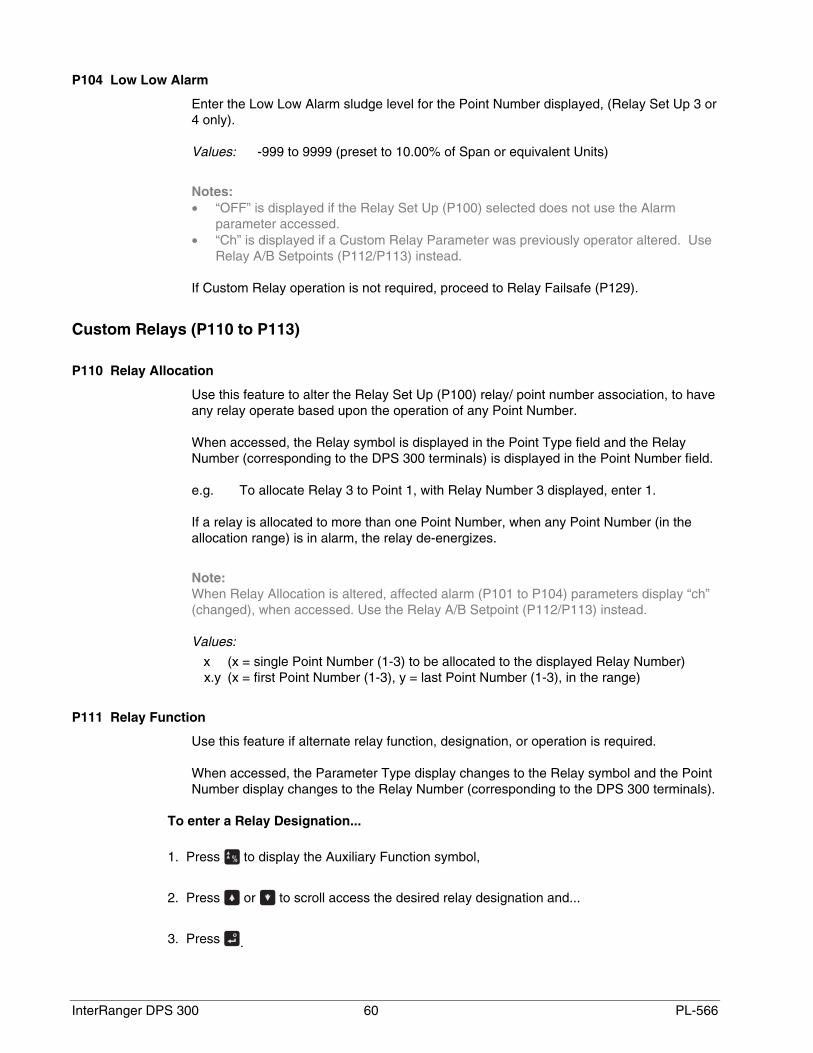
InterRanger DPS 300 60 PL-566
P104 Low Low Alarm
Enter the Low Low Alarm sludge level for the Point Number displayed, (Relay Set Up 3 or4 only).
Values: -999 to 9999 (preset to 10.00% of Span or equivalent Units)
Notes:• “OFF” is displayed if the Relay Set Up (P100) selected does not use the Alarm
parameter accessed.• “Ch” is displayed if a Custom Relay Parameter was previously operator altered. Use
Relay A/B Setpoints (P112/P113) instead.
If Custom Relay operation is not required, proceed to Relay Failsafe (P129).
Custom Relays (P110 to P113)
P110 Relay Allocation
Use this feature to alter the Relay Set Up (P100) relay/ point number association, to haveany relay operate based upon the operation of any Point Number.
When accessed, the Relay symbol is displayed in the Point Type field and the RelayNumber (corresponding to the DPS 300 terminals) is displayed in the Point Number field.
e.g. To allocate Relay 3 to Point 1, with Relay Number 3 displayed, enter 1.
If a relay is allocated to more than one Point Number, when any Point Number (in theallocation range) is in alarm, the relay de-energizes.
Note:When Relay Allocation is altered, affected alarm (P101 to P104) parameters display “ch”(changed), when accessed. Use the Relay A/B Setpoint (P112/P113) instead.
Values:
x (x = single Point Number (1-3) to be allocated to the displayed Relay Number)x.y (x = first Point Number (1-3), y = last Point Number (1-3), in the range)
P111 Relay Function
Use this feature if alternate relay function, designation, or operation is required.
When accessed, the Parameter Type display changes to the Relay symbol and the PointNumber display changes to the Relay Number (corresponding to the DPS 300 terminals).
To enter a Relay Designation...
1. Press to display the Auxiliary Function symbol,
2. Press or to scroll access the desired relay designation and...
3. Press .

PL-566 61 InterRanger DPS 300
FUNCTION DESIGNATION OPERATION
Level LL, L, H, or HH Similar to Standard Alarms but with Relay A/B Setpoints
In Bounds b1 or b2 * Alarms when level is between the Relay A/B Setpoints
Out of Bounds b1 or b2 * Alarms when level is not between the Relay A/B Setpoints
Rate r1 or r2 * Level rate of change alarm with Relay A/B Setpoints
Temperature Not applicable Alarm is activated by independent Relay A/B Setpoints
LOE Not applicable Relay de-energizes in the event of Failsafe timer (P700) expiry
Cable fault Not applicable Relay de-energizes under transducer short or opened condition
Pump Not applicable With independent Relay A/B Setpoints
Timed Not applicable Based on Relay “duration/interval” Setpoints (P114/115)
* The Relay Designation is not displayed but is included in the BIC-II (if used) data message.
Note:When the Relay Function is altered, affected Alarm Parameters (P101 to P104) display“ch” (changed) when accessed. Use the Relay A/B Setpoints (P112/P113) instead.
To reset the Relay Function to use Standard Alarms, enter the desired Relay Set Up (P100).
Values:
0 = off (relay always de-energized)1 = level alarm (preset)2 = in bounds alarm3 = out of bounds alarm4 = rate of change alarm5 = temperature alarm6 = LOE alarm (Relay A/B Setpoints are not applicable)7 = transducer cable fault alarm
50 = pump control (non-sequenced)60 = timed activation based on “duration” and “interval” setpoints
Independent Relay Setpoints
Relay A and B Setpoint values set the critical points (based on the Relay Function)where, in the Run mode ...
1. Relay status indicators are switched “ON” and “OFF”
2. Alarm Indicators (if programmed) are switched “ON” or “OFF”
3. Relays are “energized” and “de-energized”
For most Relay Functions, setpoint values represent sludge levels, entered in Units(P005) or percent of Span (P007) as referenced to Empty (P006). Temperature alarmvalues are entered in degrees Celsius (°C).
Note:Rate alarms are entered in Units / minute or percent of Span per minute. A positive valueis entered for a filling rate alarm; negative for emptying.
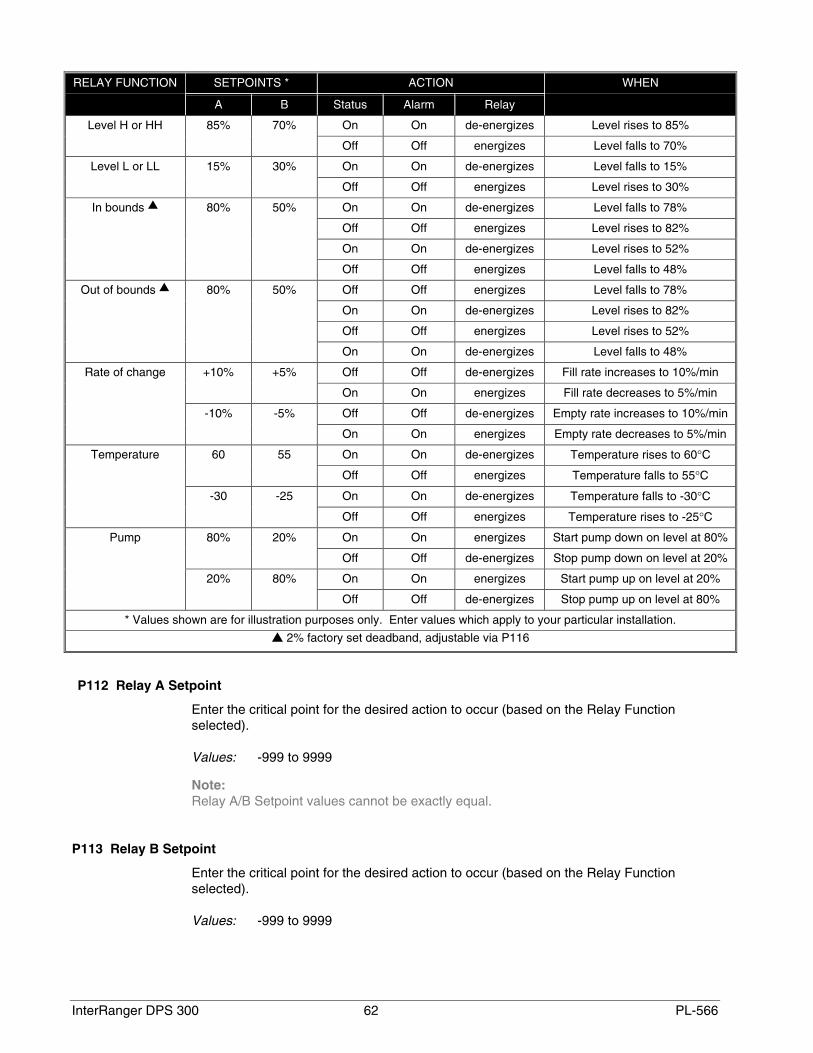
InterRanger DPS 300 62 PL-566
SETPOINTS * ACTIONRELAY FUNCTION
A B Status Alarm Relay
WHEN
On On de-energizes Level rises to 85%Level H or HH 85% 70%
Off Off energizes Level falls to 70%
On On de-energizes Level falls to 15%Level L or LL 15% 30%
Off Off energizes Level rises to 30%
On On de-energizes Level falls to 78%
Off Off energizes Level rises to 82%
On On de-energizes Level rises to 52%
In bounds 80% 50%
Off Off energizes Level falls to 48%
Off Off energizes Level falls to 78%
On On de-energizes Level rises to 82%
Off Off energizes Level rises to 52%
Out of bounds 80% 50%
On On de-energizes Level falls to 48%
Off Off de-energizes Fill rate increases to 10%/min+10% +5%
On On energizes Fill rate decreases to 5%/min
Off Off de-energizes Empty rate increases to 10%/min
Rate of change
-10% -5%
On On energizes Empty rate decreases to 5%/min
On On de-energizes Temperature rises to 60°C60 55
Off Off energizes Temperature falls to 55°C
On On de-energizes Temperature falls to -30°C
Temperature
-30 -25
Off Off energizes Temperature rises to -25°C
On On energizes Start pump down on level at 80%80% 20%
Off Off de-energizes Stop pump down on level at 20%
On On energizes Start pump up on level at 20%
Pump
20% 80%
Off Off de-energizes Stop pump up on level at 80%
* Values shown are for illustration purposes only. Enter values which apply to your particular installation.
2% factory set deadband, adjustable via P116
P112 Relay A Setpoint
Enter the critical point for the desired action to occur (based on the Relay Functionselected).
Values: -999 to 9999
Note:Relay A/B Setpoint values cannot be exactly equal.
P113 Relay B Setpoint
Enter the critical point for the desired action to occur (based on the Relay Functionselected).
Values: -999 to 9999

PL-566 63 InterRanger DPS 300
P114 Relay “duration” Setpoint
The length of time in minutes the relay is to be energized.
Enter the length of time (in minutes) for the relay to remain energized.
Values: 0.000 to 9999 (minutes)Preset: 0.000 min
Note:This value must be less than the “interval” setpoint or the relay will never reset.
P115 Relay “interval” Setpoint
The length of time in hours between timed starts.
Enter the length of time (in hours) between relay activation.
Values: 0.000 to 9999 (hours)Preset: 0.000 hrs
Note:This value must be greater than the “duration” setpoint or the relay will never reset.
P116 Bound Alarm Deadband
For `in bounds' and `out of bounds' RelayFunctions (P111 = 2 and 3 respectively), adead band prevents relay chatter due tomaterial level fluctuations at the upper orlower setpoint.
Enter dead band in % of span or units ofP005. (Factory set at 2%).
The dead band value is applied above andbelow the upper and lower bound setpoints.
P129 Relay Failsafe
Use this feature for relay failsafe operation independent from the Failsafe Material Level(P070).
When accessed, the Parameter Type display changes to the Relay symbol and the PointNumber display changes to the Relay Number (corresponding to the DPS 300 terminals)
Select:
“OFF” to have the relay respond to the Failsafe Material Level (P071).“HOLd to hold the relay at the “last known” state until normal operation resumes,“dE” to have the relay de-energize immediately, or“En” to have the relay energize immediately,
actual ‘on’
setpoint
actual ‘off’
P116, deadband
P116, deadband
e.g. in bounds, lower setpoint

InterRanger DPS 300 64 PL-566
When the Relay Function (P111) is set for:
• “alarm” (any option other than “pump”), this feature is preset to “OFF”.
• “pump”, this feature is preset to “dE”.
To select an independent Relay Failsafe option value:
1. Press to display to the Auxiliary Function symbol,
2. Press or , to scroll access the failsafe options.
3. Press , with the desired option displayed.
Values:
“OFF”“HOLd”“dE”“En”
mA Output Parameters (P200 to P203, P210 to P215, P219)
If DPS 300 mA outputs are to be used, alter the following parameters as required. Otherwise, proceed to OPERATION.
When an mA Output Parameter is accessed, the mA symbol is displayed in the PointType field and the mA output number (corresponding to the DPS 300 terminals) isdisplayed in the Point Number field.
P200 mA Range
Enter the desired range of the mA output displayed.
Value:
0 = OFF1 = 0 to 20 mA2 = 4 to 20 mA (preset)3 = 20 to 0 mA4 = 20 to 4 mA
P201 mA Function
Use this feature to alter the automatic mA output/measurement relationship, if desired.
The mA Function automatically corresponds to “level”, “space”, or “distance” based uponOperation (P001). If a Tank Shape (P050) is programmed, the mA Function automaticallycorresponds to volume (unless the mA Allocation has been altered).
Values:
1 = level2 = space3 = distance4 = volume

PL-566 65 InterRanger DPS 300
P202 mA Allocation
Use this feature if Point Number to mA output allocation alteration is required. Enter thePoint Number(s) the mA output displayed, is to be based upon.
As preset, mA outputs 1 and 2 are allocated to Point Numbers 1 and 2 respectively.
If Point 1 and 2 are allocated to a single mA output, the output value represents the DualPoint Average. (The Quick Start Parameter values should be identical for both points).
When both mA outputs are allocated to the same Point Number, the mA Setpointparameters may be used to establish two separate or overlapping mA output spans.However, the mA Value / Transducer (P203) corresponds to mA Output 1 only.
Values:1 = Point 12 = Point 2
1.2 = Dual Point Average
P203 (V) mA Value / Transducer
View the current value of the mA output associated with the Point Number displayed.
This is the Auxiliary Reading displayed when [mA] is pressed in the RUN mode.
If both mA outputs are allocated to the same Point Number, the value of mA Output 1 isdisplayed.
Values: 0.000 to 22.00
P210 0/4 mA Setpoint
Use this feature to reference the minimum mA output to any point in the measurementrange.
Enter the material level (referenced to Empty, P006) corresponding to the minimum mAoutput.
This feature is preset to 0% or 100% of Span (P007) as determined by Operation (P001).
Typically, this value is entered in Units (P005) or percent of Span (P007). If mA Functionis set for “volume”, enter the value in the Max Volume (P051) units or in percent of MaxVolume.
Values: -999 to 9999
P211 20 mA Setpoint
Use this feature to reference the 20 mA output to any point in the measurement range.
Enter the sludge level (referenced to Empty, P006) corresponding to 20 mA.
This feature is preset to 0% or 100% of Span (P007) as determined by Operation (P001).

InterRanger DPS 300 66 PL-566
Typically, the value is entered in Units (P005) or percent of Span (P007). If mA Functionis set for “volume”, enter the value in the Max Volume (P051) units or as a percent of MaxVolume.
Values: -999 to 9999
P212 mA Min Limit
Use this feature to prevent the mA output from falling below the minimum acceptable mAinput value (preset to 3.800 mA) of the device connected.
Values: 0.000 to 22.00
P213 mA Max Limit
Use this feature to prevent the mA output from exceeding the maximum acceptable mAinput value (preset to 20.20 mA) of the device connected.
Values: 0.000 to 22.00
P214 4 mA Trim
Use this feature (in combination with 20 mA Trim) if the device connected to the mAoutput displayed is out of calibration, yet device recalibration is impractical.
Adjust this value (preset to 0.000) as required to make the device connected indicate4.000 mA when this parameter is accessed.
Values: -1.00 to 1.000
P215 20 mA Trim
Use this feature (in combination with 4 mA Trim) if the device connected to the mA outputdisplayed is out of calibration, yet device recalibration is impractical.
Adjust this value (preset to 0.000) as required to make the device connected indicate20.00 mA when this parameter is accessed.
Values: -1.00 to 1.000
P219 mA Failsafe
Use this feature if mA output failsafe operation, independent from the Failsafe MaterialLevel (P071) is desired.
To select an independent mA Failsafe option value:
1. Press to display the Auxiliary Function symbol,
2. Press or , to scroll access the failsafe options.
3. Press with the desired option displayed.

PL-566 67 InterRanger DPS 300
Values:
“OFF” to have the mA output respond to the Failsafe Material Level (P071).“HOLd” to hold the output at the “last known” value until normal operation
resumes.“LOW” to produce the “Empty” mA output immediately on Failsafe Timer (P070)
expiry.“HIGH” to produce the “Span” mA output immediately on Failsafe Timer (P070)
expiry.
Alternatively, to produce an immediate mA output at a specific value, enter the valuerequired.
Values: 0.000 to 22.00

InterRanger DPS 300 68 PL-566
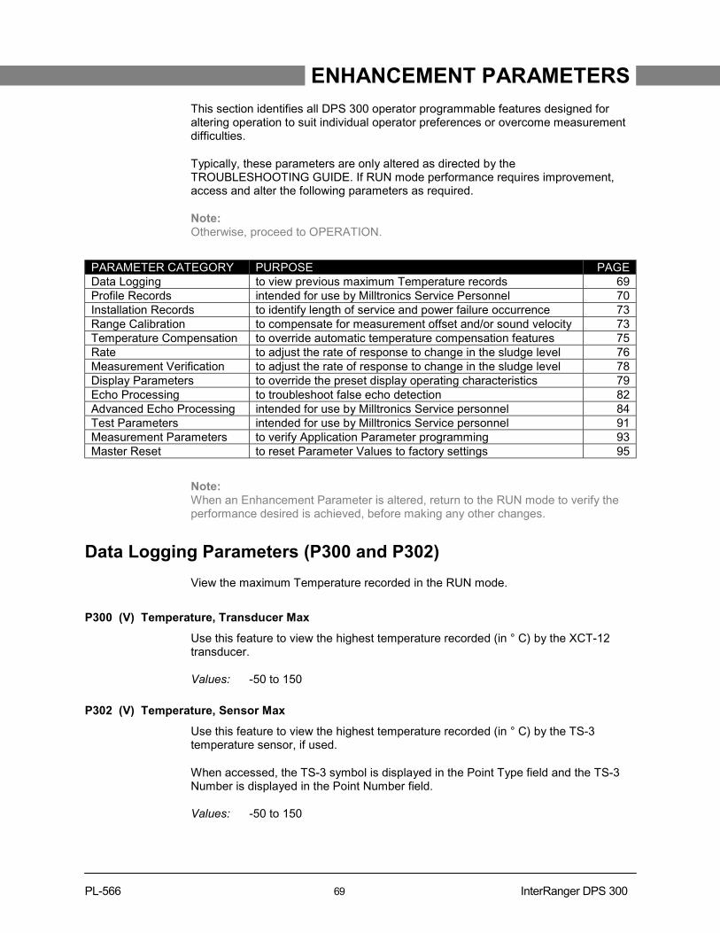
PL-566 69 InterRanger DPS 300
ENHANCEMENT PARAMETERS
This section identifies all DPS 300 operator programmable features designed foraltering operation to suit individual operator preferences or overcome measurementdifficulties.
Typically, these parameters are only altered as directed by theTROUBLESHOOTING GUIDE. If RUN mode performance requires improvement,access and alter the following parameters as required.
Note:Otherwise, proceed to OPERATION.
PARAMETER CATEGORY PURPOSE PAGEData Logging to view previous maximum Temperature records 69Profile Records intended for use by Milltronics Service Personnel 70Installation Records to identify length of service and power failure occurrence 73Range Calibration to compensate for measurement offset and/or sound velocity 73Temperature Compensation to override automatic temperature compensation features 75Rate to adjust the rate of response to change in the sludge level 76Measurement Verification to adjust the rate of response to change in the sludge level 78Display Parameters to override the preset display operating characteristics 79Echo Processing to troubleshoot false echo detection 82Advanced Echo Processing intended for use by Milltronics Service personnel 84Test Parameters intended for use by Milltronics Service personnel 91Measurement Parameters to verify Application Parameter programming 93Master Reset to reset Parameter Values to factory settings 95
Note:When an Enhancement Parameter is altered, return to the RUN mode to verify theperformance desired is achieved, before making any other changes.
Data Logging Parameters (P300 and P302)
View the maximum Temperature recorded in the RUN mode.
P300 (V) Temperature, Transducer Max
Use this feature to view the highest temperature recorded (in ° C) by the XCT-12transducer.
Values: -50 to 150
P302 (V) Temperature, Sensor Max
Use this feature to view the highest temperature recorded (in ° C) by the TS-3temperature sensor, if used.
When accessed, the TS-3 symbol is displayed in the Point Type field and the TS-3Number is displayed in the Point Number field.
Values: -50 to 150
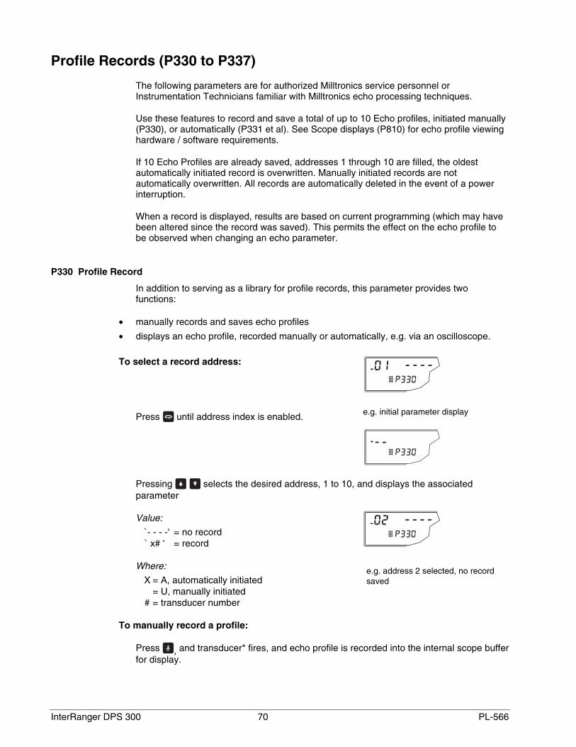
InterRanger DPS 300 70 PL-566
Profile Records (P330 to P337)
The following parameters are for authorized Milltronics service personnel orInstrumentation Technicians familiar with Milltronics echo processing techniques.
Use these features to record and save a total of up to 10 Echo profiles, initiated manually(P330), or automatically (P331 et al). See Scope displays (P810) for echo profile viewinghardware / software requirements.
If 10 Echo Profiles are already saved, addresses 1 through 10 are filled, the oldestautomatically initiated record is overwritten. Manually initiated records are notautomatically overwritten. All records are automatically deleted in the event of a powerinterruption.
When a record is displayed, results are based on current programming (which may havebeen altered since the record was saved). This permits the effect on the echo profile tobe observed when changing an echo parameter.
P330 Profile Record
In addition to serving as a library for profile records, this parameter provides twofunctions:
• manually records and saves echo profiles
• displays an echo profile, recorded manually or automatically, e.g. via an oscilloscope.
To select a record address:
Press until address index is enabled.
Pressing selects the desired address, 1 to 10, and displays the associatedparameter
Value:
`- - - -' = no record` x# ' = record
Where:
X = A, automatically initiated= U, manually initiated
# = transducer number
To manually record a profile:
Press , and transducer* fires, and echo profile is recorded into the internal scope bufferfor display.
e.g. initial parameter display
e.g. address 2 selected, no recordsaved
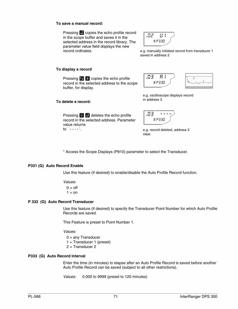
PL-566 71 InterRanger DPS 300
To save a manual record:
Pressing copies the echo profile recordin the scope buffer and saves it in theselected address in the record library. Theparameter value field displays the newrecord ordinates.
To display a record
Pressing copies the echo profilerecord in the selected address to the scopebuffer, for display.
To delete a record:
Pressing deletes the echo profilerecord in the selected address. Parametervalue returnsto ` - - - - '.
* Access the Scope Displays (P810) parameter to select the Transducer.
P331 (G) Auto Record Enable
Use this feature (if desired) to enable/disable the Auto Profile Record function.
Values:
0 = off1 = on
P 332 (G) Auto Record Transducer
Use this feature (if desired) to specify the Transducer Point Number for which Auto ProfileRecords are saved.
This Feature is preset to Point Number 1.
Values:
0 = any Transducer1 = Transducer 1 (preset)2 = Transducer 2
P333 (G) Auto Record Interval
Enter the time (in minutes) to elapse after an Auto Profile Record is saved before anotherAuto Profile Record can be saved (subject to all other restrictions).
Values: 0.000 to 9999 (preset to 120 minutes)
e.g. manually initiated record from transducer 1saved in address 2
e.g. oscilloscope displays recordin address 3
e.g. record deleted, address 3clear

InterRanger DPS 300 72 PL-566
Auto Record A/B Setpoint
Use Auto Record A Setpoint (P334) and Auto Record B Setpoint (P335) to define theboundaries within which the level must be, for the resultant Echo Profile to be consideredfor an Auto Profile Record.
If “ - - - - “ is displayed for either P334 or P335, Auto Profile Records are savedregardless of current level (subject to all other restrictions).
Enter the level value in Units (P005) or percent of Span (P007) as referenced to Empty(P006).
(Ensure the % Symbol is displayed before attempting to enter a value in percent, seePROGRAMMING / Keypad).
P334 (G) Auto Record A Setpoint
Enter the critical level which, in conjunction with Auto Record B Setpoint, defines theboundaries for Auto Profile Records to be stored.
Values: -999 to 9999
P335 (G) Auto Record B Setpoint
Enter the critical level which, in conjunction with Auto Record A Setpoint, defines theboundaries for Auto Profile Records to be stored.
Values: -999 to 9999
P336 (G) Auto Record Filling/Emptying
Use this feature to restrict Auto Profile Records from being saved unless the level isrising, falling or either.
If the level changes at a rate in excess of the corresponding Filling/ Emptying Indicator(P702 / P703) values, the Echo Profile is saved subject to this and other Auto ProfileRecord restrictions).
Values:
0 = Auto Profile Record on filling or emptying (preset).1 = Auto Profile Record on filling only.2 = Auto Profile Record on emptying only.
P337 (G) Auto Record LOE Time
Use this feature to restrict Auto Profile Records from being saved unless an extendedloss of echo (LOE) condition occurs.
If the LOE condition exceeds the period entered (in seconds) the Echo Profile is savedsubject to this and other Auto Profile Record restrictions.
When set for “0” (preset), LOE is not required for an Auto Profile Record to be saved.
Values: 0.0 to 9999
PL-566 73 InterRanger DPS 300
Installation Records (P340 to P342)
P340 (V) Date of Manufacture
View the date of manufacture of this DPS.
Values: YY:MM:DD
P341 (V) Run Time
View the accumulated number of days this DPS has been operating, since the Date ofManufacture.
Values: 0.000 to 9999
P342 (V) Start Ups
View the accumulated number of times power has been applied to the DPS (following apower interruption), since the Date of Manufacture (P340).
Values: 1 to 9999
Range Calibration Parameters (P650 to P654)
P650 Offset Calibration
Use this feature if the Empty (P006) value was estimated or if the reported sludge level isconsistently high or low by a fixed amount (e.g. 2 cm).
Before using this feature, verify the:
• Empty (P006) value (as measured or estimated) was entered correctly.
• Temperature (P664) is correct.
• Offset Reading (P062) value (if used) was entered correctly.
To perform an Offset Calibration:
With the material at a high steady level...
1. Press to display the calculated distance*.
2. Repeat step 1 at least 5 times to overcome Echo Lock (P721) and verify repeatability.
3. Measure the actual distance* (e.g. with a tape measure).
4. Enter the actual value. (The Offset Correction amount is stored in P652).
Values: -999 to 9999

InterRanger DPS 300 74 PL-566
P651 Sound Velocity Calibration
To perform a Sound Velocity Calibration:
With the sludge at a low level, and unagitated…
1. Press to display the calculated distance*.
2. Repeat step 2 at least 5 times to overcome Echo Lock (P721) and verify repeatability.
3. Measure the actual distance* (e.g. with a Sludge Judge).
4. Enter the actual value. (Velocity parameters P653 and P654 are adjusted accordingly).
Values: -999 to 9999
* When Operation (P001) for the Point Number displayed is set for:
• “level”, the distance is from Empty (P006) to the sludge surface.
• “space”, the distance is from Span (P007) to the sludge surface.
• “distance”, the distance is from the transducer face to the sludge surface.
P652 Offset Correction
View the amount of offset applied to the Reading.
This value is automatically adjusted when an Offset Calibration is performed.
Alternatively, if the amount of Offset Correction required is known (and performing anOffset Calibration is not desired), enter the amount to be added to the Reading beforedisplay.
Values: -999 to 9999
P653 Velocity
View the actual sound velocity in water at the current temperature (P664).
When a Sound Velocity Calibration is performed, this value is automatically adjusted. Thechange in the sound velocity reflects the characteristics of the prevailing conditions; i.e.wastewater temperature and turbidity.
Alternatively, if the current sound velocity is known, enter the current sound velocity. (Refer to TECHNICAL REFERENCE / Sound Velocity).
The units used are m/s if P005 = 1, 2, or 3 (ft/s if P005 = 4 or 5).
Values: 50.00 to 2000 m/s (164.0 to 6562 ft/s)
P654 Velocity at 20°C
View the value of the sound velocity in water normalized to 20°C (68°F) used to calculateSound Velocity (P653), using Temperature (P664) based on the sound velocity vs.temperature characteristics of water.
PL-566 75 InterRanger DPS 300
After a Sound Velocity Calibration, this value represents the actual sound.
The velocity of sound in water is typically 1483 m/s (4864 ft/s).
The units used are m/s if P005 = 1, 2, or 3 (or ft/s if P005 = 4 or 5).
Values: 50.00 to 2000 m/s (164.0 to 6562 ft/s)
Temperature Compensation Parameters (P660 to P664)
P660 Temp Source
This feature is preset to “AUTO”. On scanning a transducer, the DPS 300 scans the TS-3temperature sensor assigned to the transducer. If a TS-3 sensor is not connected, thetemperature measurement from the transducer is used.
If the wastewater temperature between the transducer and the sludge varies, connect aTS-3 Temperature Sensor between these two points and select “average”.
Values:
1 = AUTO2 = Temp Fixed 3 = XCT-12 Transducer4 = TS-3 Temperature Sensor5 = Average6 = TS-3 SENSOR # 1
P661 Temp Fixed
Use this feature if a temperature sensing device is not used.
Enter the temperature (in °C) of the clarifier wastewater. If the temperature varies withdistance from the transducer, enter the average temperature. This value is preset to20.00°C.
Values: -50 to 150
P662 Temperature Sensor Allocation
As preset, TS-3 number 1 and 2 are allocated to Point Number 1 and 2 respectively.
To alter this allocation, enter the TS-3 number which is used for the distance calculationof the Point Number displayed.
When both TS-3 temperature sensors are allocated to one Point Number, thetemperature measurements from each sensor are averaged for that clarifier.
Values:
1 = TS-3 number 12 = TS-3 number 2
1.2 = TS-3 number 1 and 2 average
InterRanger DPS 300 76 PL-566
P663 Temperature Transducer Allocation
As preset, the temperature sensor inside of transducer number 1 and 2 are allocated toPoint Numbers 1 and 2 respectively. So, the temperature sensor of transducer 1 isallocated to Point Number 1 and 2 is allocated to 2.
To alter this allocation, enter the transducer number whose temperature measurementwill be used for the distance calculation of the Point Number displayed.
When both transducers are allocated to one Point Number, the temperaturemeasurements from each transducer are averaged for that clarifier.
Values:
1 = Transducer number 12 = Transducer number 2
1.2 = Transducer number 1 and 2 average
P664 (V) Temperature
View the current temperature in °C.
This is the value displayed when is pressed in the RUN mode.
If Temp Source (P660) is set to any value other than Fixed Temp, the value displayed isthe temperature measured. If Temp Source is set to Fixed Temp, the P661 value isdisplayed.
Values: -50 to 150
Rate Parameters (P700 to P707)
P700 Max Fill Rate
Adjust the DPS 300 response to increases in the actual sludge level (or advance to ahigher Failsafe Material Level, P071).
Note:Enter a value slightly greater than the maximum clarifier filling rate.
The value is in Units (P005) or % of Span (P007) per minute.
Values: 0.000 to 9999
P701 Max Empty Rate
Adjust the DPS 300 response to decreases in the actual sludge level (or advance to alower Failsafe Material Level, P071).
Note:Enter a value slightly greater than the maximum clarifier emptying rate.
The value is in Units (P005) or % of Span (P007) per minute.
Values: 0.000 to 9999

PL-566 77 InterRanger DPS 300
P702 Filling Indicator
Enter the fill rate required to activate the LCD Material Filling indicator.
The value is in Units (P005) or % of Span (P007) per minute is automatically set to 10%of the Max Fill Rate (P700).
Values: -999 to 9999
P703 Emptying Indicator
Enter the empty rate required to activate the LCD Material Emptying indicator.
The value is in Units (P005) or % of Span (P007) per minute is automatically set to 10%of the Max Empty Rate (P701).
Values: -999 to 9999
P704 Rate Filter
Use this feature to avoid Rate Value (P707) fluctuations due to an unstable sludgesurface.
If the sludge surface rises and falls quickly, the filling or emptying indicator may toggleunnecessarily, and may cause relay chatter if relays are controlled by rate. This featurecan be used to average those changes.
This value automatically alters the Rate Update Time (P705) and / or Rate UpdateDistance (P706). Alternatively, these parameter values may be altered independently.
Enter the time period/distance the Rate Value is averaged before display update.
Values:
0 = rate display not required1 = continuously averaged and updated2 = 1 minute or 50 mm (2 in)3 = 5 minutes or 100 mm (3.9 in)4 = 10 minutes or 300 mm (11.8 in)5 = 10 minutes or 1000 mm (39.4 in)
P705 Rate Update Time
Enter the time period (in seconds) over which the material level rate of change isaveraged before Rate Value update.
Values: 0.000 to 9999
P706 Rate Update Distance
Enter the sludge level change (in meters) to initiate a Rate Value update.
Values: 0.000 to 9999
InterRanger DPS 300 78 PL-566
P707 (V) Rate Value
View the rate of sludge level change (in Units (P005) or % of Span (P007) per minute).
(A negative rate indicates the clarifier is emptying).
This is the value displayed when is pressed in the RUN mode.
Values: 0.000 to 9999
Measurement Verification Parameters (P710 to P713)
P710 Fuzz Filter
Use this feature to stabilize the reported sludge level, due to level fluctuations (such as arippling surface), within the Echo Lock Window (P713).
The value is in % of Span. The higher the value entered, the greater the fluctuationstabilized. (0 = off)
Values: 0 to 100
P711 Echo Lock
Use this feature to determine how quickly the DPS 300 locks onto a new echo.
The value is automatically altered when Material (P002) is altered.
When set for “skimmer” or “material agitator”, a new measurement outside of the EchoLock Window (P713) must meet the sampling criterion (P712).
For “total lock”, Echo Lock Window (P713) is preset to “0”. The DPS 300 continuouslysearches for the best echo according to the algorithm chosen (P820). If the selected echois within the window, the window is then centred about the echo. If not, the windowwidens with each successive shot until the selected echo is within the window. Thewindow then returns to its normal width.
When Echo Lock is turned “off” the DPS 300 responds immediately to a newmeasurement as restricted by the Max Fill / Empty Rate (P700/P701), howevermeasurement reliability is affected.
Values:
0 = off1 = skimmer2 = material agitator3 = total lock
P712 Echo Lock Sampling
Use this parameter to specify the number of echos required to move the current levelvalue outside of the Echo Lock Window.
The two values, represented as x.y are for echos above and below the current Echo LockWindow, respectively.
PL-566 79 InterRanger DPS 300
When P711 Echo Lock is set to “1, skimmer” or “2, material agitator” then echos detectedoutside of the Echo Lock Window are counted and a new level value is displayed onlyafter the counted echos exceed the Echo Lock Sampling value.
P711 value P712 preset value1, skimmer 5:5
2, material agitator 5:2
e.g. : P711 = 2, material agitator
P712 = 5:2A new reading will not be validated unless 5 consecutive measurements arehigher or 2 consecutive measurements are lower than the current Echo LockWindow.
Values: x.y
x= # of `above' echoes
y = # of `below' echoes
Note:Resetting P711 returns P712 to the respective preset values.
P713 Echo Lock Window
Use this feature to adjust the size of the Echo Lock Window (in ms).
The Echo Lock Window is a “time window” (in ms) placed on either side of the echo usedto derive the Reading. When a new measurement falls within the window, the window isre-centred and the new Reading is calculated. Otherwise, the new measurement isverified by Echo Lock (P711) before the DPS 300 updates the reading.
When “0” is entered (preset), the window is automatically calculated based on the MaxFill / Empty Rate ( P700 / P701).
Values: 0.000 to 9999
Display Parameters (P730 to P733, P740)
P730 (G) Auxiliary Reading
Use this feature to display operator selected Auxiliary Readings temporarily.
Select “OFF” to display Auxiliary Readings temporarily. Select “HOLd” to display AuxiliaryReadings until another Auxiliary Reading is selected.
(See OPERATION Keypad for RUN mode Auxiliary Reading selection.)
To select the Auxiliary Reading operation desired.
1. Press to display the Auxiliary Function symbol.
2. Press or to display the “OFF” or “HOLd” (preset) option as desired.
3. Press .
If desired, also enter the Parameter Number to default in the Auxiliary Reading display.
Values: 000 to 999
InterRanger DPS 300 80 PL-566
P731 (G) Auxiliary Reading Key
Use this feature to enable a specific Parameter Value to be monitored in the RUN mode.
Enter the Parameter Number whose value is to be displayed in the Auxiliary Reading fieldwhen is pressed in the RUN mode.
(See OPERATION Keypad for RUN mode Auxiliary Reading selection.)
Values: 000 to 999 (preset to Material Measurement, P921)
P732 (G) Display Delay
Use this feature if the Point Number display scrolls too quickly in the RUN mode.
Enter the delay (in seconds) before the display advances to the next Point Number.
(Point Number display scrolling is independent from transducer scanning.)
Values: 0.5 to 10 (preset to 1.5 seconds)
P733 (G) Scroll Access
Use this feature to select the programming mode parameter scroll access option desired.
Select:
“off” to scroll access all operator accessible parameters.“smart” to scroll access Quick Start, previously altered, and tagged
parameters.“tagged” to scroll access operator tagged parameters only.
Any accessed parameter may be tagged or untagged by pressing .
is displayed when a previously tagged or altered parameter is accessed.
Values:
0 = off1 = smart (preset)2 = tagged
Peripheral Communication Support Parameters (P740 to P772)
P740 Peripheral Communications
Use this feature to select the DPS 300 to communication message format.
Select:
“off” if the communication port is not used, to increase the DPS 300processing speed.
“normal” to have messages transmitted in a continuous string of characters. (Requires less DPS 300 processing time than formatted messages).
“formatted” to have commas inserted between the message fields for easiermessage dissemination (when viewed on a monitor).

PL-566 81 InterRanger DPS 300
Note:Refer to TECHNICAL REFERENCE Communication Support if a PeripheralCommunication is required.
Values:
0 = off1 = normal messages (preset)2 = formatted messages
P748 RS485 Termination
Single point termination may be required to minimize transmission reflections, onlong cable runs typical of 500m or more. Turn on the termination if required.
Values:
0 = off1 = on
P749 Serial Bus Type (V)
Displays the type of communication bus the DPS 300 is currently set for. If there isno connection, the DPS 300 defaults to RS-485. If a bus type other than RS-485 isconnected, the DPS 300 displays the type of bus it is, or is attempting to,communicate with.
Displays:
232 = RS-232485 = RS-485 (default setting when nothing is connected)bPL= bipolar current looprJ11 = for Milltronics use
P772 Baud Rate
The communication rate with the master device (i.e. Dolphin Plus on a PC).
This parameter specifies the rate of communication in Kbaud. Any value may beentered but only the values shown below are supported.
Note:This parameter is not reset by P999.
Values:
4.8 = 48009.6 = 960019.2 = 19 20038.4 = 38 400 (preset)
InterRanger DPS 300 82 PL-566
SmartLinx® Parameters (P790 to P792)
These parameters are specific to the SmartLinx® module installed. Refer to the moduledocumentation for a list and description of the specific parameter requirements.
P790 Hardware Error
Use this feature to display the results of ongoing hardware tests within thecommunications circuitry. If any test does not meet the PASS requirements,communication halts and tests are repeated until PASS requirements are met.Communications then resumes.
Displays:
PASS: no problemFAIL: faulty SmartLinx module or DPS 300ERR1: unknown protocol, upgrade the DPS 300 software
P791 Bus Error
This feature indicates if an error condition is occurring on the bus.
Displays:
0 = no errorØ = error code, refer to the SmartLinx module documentation for explanation of the
error code
P792 Bus Error Count
This register increments by 1 each time a bus error (P752) is reported. The resister isfactory set at 0 and can be preset to any value. The register is reset to 0 by the masterreset (P999).
Echo Processing Parameters (P800 to P807)
P800 Near Blanking
Use this feature if the material level is incorrectly reported to be near the transducer face.
Near Blanking may be extended to overcome measurement difficulties which cannototherwise be corrected by transducer location, mounting, or aiming modification. ExtendNear Blanking to 150 mm (6 in) beyond the incorrect distance measured.
This parameter is preset to 1.000 m or equivalent Units (P005) regardless of Empty(P006).
Note:Ensure the Near Blanking distance is less than Empty (P006) - Span (P007).
To reset the automatic Near Blanking value press .
Values: 0.000 to 9999 (preset 1.00m)
PL-566 83 InterRanger DPS 300
P801 Range Extension
Use this feature if an incorrect level is reported (when material level is lower than Empty,P006).
Range Extension is the distance in Units (P005) or % of Span (P007) beyond Empty,which is still ultrasonically measurable.
If Empty is substantially higher than the actual clarifier bottom, increase Range Extensionsuch that Empty plus Range Extension is greater than the transducer to clarifier bottomdistance.
Values: 0.000 to 9999
P804 Confidence Threshold
Use this feature when an incorrect material level is reported.
The Confidence Thresholds are preset to 10 and 5 respectively. If the Echo Confidence(P805) of a particular echo exceeds the Confidence Threshold, that echo is consideredfor evaluation by Sonic Intelligence ™.
Values: 0:y y = 0 to 99
P805 (V) Echo Confidence
Use this feature to monitor the effect of transducer aiming, location, and mechanicaltransducer / mounting isolation.
This is the value displayed when is pressed for 4 seconds in the RUN mode.
Echo Confidence is displayed as:
“E” is displayed if the transducer cable is open or short circuited.
Values: 0:y y = 0 to 99
P806 (V) Echo Strength
Use this feature to view the strength (in dB above 1 µV rms) of the echo selected to basethe distance calculation upon.
Values: 0 to 99
P807 (V) Noise
Observe the average and peak ambient noise (in dB above 1 µV rms) being processed.
The noise level is a combination of transient acoustic noise and electrical noise (inducedinto the transducer cable or receiving circuitry itself).
Values: x.y x = average (-99 to 99), y = peak (-99 to 99)

InterRanger DPS 300 84 PL-566
Advanced Echo Processing (P810 to P853)
Note:The following Echo Processing parameters are intended for use by authorized MilltronicsService personnel or Industrial Instrumentation Technicians familiar with Milltronicsultrasonic echo processing techniques.
Anatomy of an Echo Profile
The relevant parts of an echo profile are listed here. These are visible in either DolphinPlus or an oscilloscope.
P810 Scope Displays
Use this feature to monitor the results of Echo Processing parameter alterations.
Connect an oscilloscope to Display Board TP4, TP5, and TP6 (GND, SCOPE andSYNC).
Observe any combination of the following Scope Displays:
DISPLAY DISPLAY SYMBOL P C n u
Echo Profile
TVT Curve
Echo Marker
Echo Lock Window
echo profile
TVT curveselected echo
echo lock windowecho marker

PL-566 85 InterRanger DPS 300
To select the desired Scope Display...
1. Press to display the Auxiliary Function symbol,
2. Press or to scroll access the desired Reading display symbols.
3. Press to select the displayed symbols.
Alternatively, a 4 digit binary value may be entered, where a “0” turns the associatedsignal display “off”, and a “1” turns the associated display “on”.
e.g. 1110 = PCn_ = Echo Profile, TVT Curve, and Echo Marker displays on.
See TECHNICAL REFERENCE / Echo Processing for more Scope Display illustrations.
Use the Scope Displays after pressing (in the program mode) to observe the result ofEcho Processing parameter alterations. (Take several measurements to verifymeasurement repeatability and overcome Echo Lock (P711) restrictions).
As preset, all displays are off.
P815 (V) Echo Time
Observe the time (in ms) between the transmit pulse and the processed echo, includingdelays such as filtering and rate limit.
P816 (V) Echo Time Raw
Observe the time of flight (in ms) between the transmit pulse and the raw echo, i.e. beforeprocessing.
Values: 0.000 to 9999
When a Profile Pointer Parameter is accessed, the Echo Lock Window scope displaychanges to a Profile Pointer display. The Profile Pointer may be moved to a number ofpoints on the Echo Profile, to gain specific information dependent upon the Profile PointerParameter used.
To move the Profile Pointer to a specific point, enter the desired value. The ProfilePointer will move to the nearest acceptable Echo Profile point. The Profile Pointer ispreset to “0”.
Alternatively, to scroll the Profile Pointer along the Echo Profile...
1. Press to display the Auxiliary Function symbol,
2. Press or to move the Profile Pointer to the left or right respectively.
When the Profile Pointer Parameters are exited and is pressed or the RUN mode isentered, the Profile Pointer display automatically changes back to the Echo Lock Windowdisplay.
P817 (V) Profile Pointer Time
Observe the time (in ms) between the transmit pulse and the Profile Pointer.
Values: 0.000 to 9999
InterRanger DPS 300 86 PL-566
P818 (V) Profile Pointer Distance
Observe the distance (in P005 Units) between the transducer face and the ProfilePointer.
Values: 0.000 to 9999
P819 (V) Profile Pointer Amplitude
Observe the amplitude (in dB above 1 µV rms) of the Echo Profile at the Profile Pointerposition.
Values: 0 to 99
P820 Algorithm
Use this feature to select the Algorithm(s) (mathematical operations) on which the SonicIntelligence™ echo selection is based.
This value is automatically altered by Material (P002).
If the wrong echo is processed, select an alternate algorithm, while observing theresultant echo processing displays.
To select an Algorithm...
1. Press to display the Auxiliary Function symbol,
2. Press or to display the desired Reading display symbol(s),
3. Press (when the desired Algorithm is displayed)
Algorithms are characterized by a combination of echo characteristics:
area = echo with most area above the TVTlargest = echo with the largest amplitude above the TVTfirst = first echo above the TVT to be receivedlast = last echo above the TVT to be received
Values:
ALF = Area, Largest, and First average.A = Area only.L = Largest onlyF = First onlyAL = Area and Largest averageAF = Area and First averageLF = Largest and First averagebLF = Largest or FirstbL = Largest onlybF = First onlyLASt = last only (first echo from empty)
PL-566 87 InterRanger DPS 300
P821 Spike Filter
Activate the Spike Filter if interference spikes are observed on the long shot Echo Profiledisplay.
Values:
0 = off1 = on (preset)
P822 Narrow Echo Filter
Use this feature to remove narrow echoes from profile.
Enter the width of false echoes (in ms), to be removed.
When a value is keyed in, the nearest acceptable value is entered.
Values: 0 = off (preset), greater = wider
P823 Reform Echo
Enter the amount (in ms) of long shot Echo Profile smoothing required to eliminate jaggedpeaks in the Echo Profile.
When a value is keyed in, the nearest acceptable value is entered.
Values: 0 = off (preset), greater = wider
P825 Echo Marker Percentage
Use this feature when the reported material level fluctuates slightly, due to a variable risein the leading or trailing edge of the selected echo on the Echo Profile.
Enter the value (in percent of echo height) to ensure the Echo Lock Window intersectsthe Echo Profile at the steepest slope of the selected echo. This value becomes thereported level.
Values: 5 to 95 (preset: 50)

InterRanger DPS 300 88 PL-566
P826 Echo Marker Position
Use this feature to determine which slope on the selected echo is used by the EchoMarker Percentage.
1 = Leading: The Echo Marker is placed on the leading edge of the selected echo (preset).
2 = Trailing: the Echo Marker is placed on the trailing edge of the selected echo.
3 = Peak: the Echo Marker is placed at the peak of the selected echo. The Echo MarkerPercentage (P825) is not used.
NoteThe Echo Lock Window (P713) is centered about the position of the Echo Marker.
P830 TVT Type
Use this feature to select the TVT Curve most suited to the material and clarifier.
This feature is automatically altered when Material (P002) is altered.
Do not select “TVT SLOPES” when the “bF or bLF” Algorithm (P820) is selected.
Values:
1 = TVT Short Curved2 = TVT Short Flat3 = TVT Long Flat4 = TVT Long Smooth Front5 = TVT Long Smooth6 = TVT Slopes
P831 TVT Shaper
Use this feature to turn the TVT Shaper “on” or “off”.
Turn the TVT Shaper “on” before altering TVT Shaper Adjust. After TVT Shaper Adjusthas been used to modify the TVT Curve (to avoid a false echo or pick up the true echo),this feature allows the TVT Shaper to be turned “on” and “off” while monitoring the effect.
echo marker (P826=3) echo lock window
echo marker (P826=2)echo profile
95%
50%
5%
5%
50%
95%
echo marker (P826=1)
echo marker % (P825)
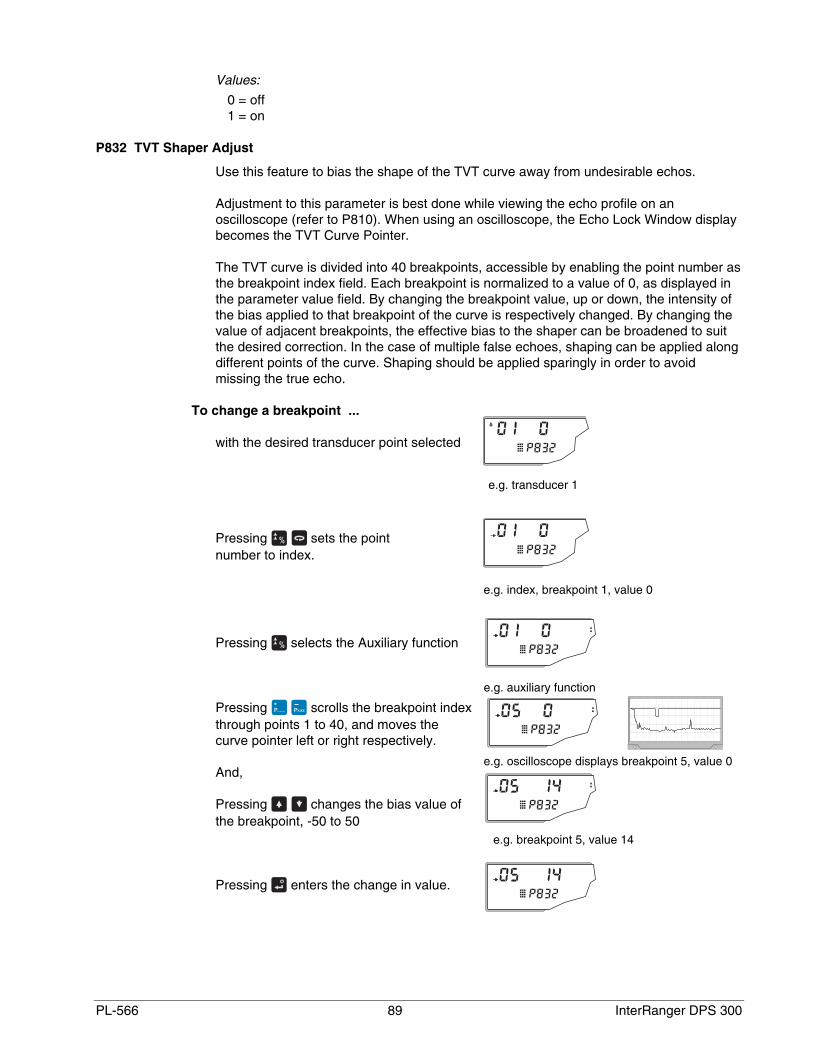
PL-566 89 InterRanger DPS 300
Values:
0 = off1 = on
P832 TVT Shaper Adjust
Use this feature to bias the shape of the TVT curve away from undesirable echos.
Adjustment to this parameter is best done while viewing the echo profile on anoscilloscope (refer to P810). When using an oscilloscope, the Echo Lock Window displaybecomes the TVT Curve Pointer.
The TVT curve is divided into 40 breakpoints, accessible by enabling the point number asthe breakpoint index field. Each breakpoint is normalized to a value of 0, as displayed inthe parameter value field. By changing the breakpoint value, up or down, the intensity ofthe bias applied to that breakpoint of the curve is respectively changed. By changing thevalue of adjacent breakpoints, the effective bias to the shaper can be broadened to suitthe desired correction. In the case of multiple false echoes, shaping can be applied alongdifferent points of the curve. Shaping should be applied sparingly in order to avoidmissing the true echo.
To change a breakpoint ...
with the desired transducer point selected
Pressing sets the pointnumber to index.
Pressing selects the Auxiliary function
Pressing scrolls the breakpoint indexthrough points 1 to 40, and moves thecurve pointer left or right respectively.
And,
Pressing changes the bias value ofthe breakpoint, -50 to 50
Pressing enters the change in value.
e.g. index, breakpoint 1, value 0
e.g. auxiliary function
e.g. transducer 1
e.g. oscilloscope displays breakpoint 5, value 0
e.g. breakpoint 5, value 14
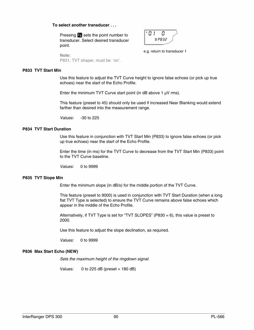
InterRanger DPS 300 90 PL-566
To select another transducer . . .
Pressing sets the point number totransducer. Select desired transducerpoint.
Note:P831, TVT shaper, must be ‘on’.
P833 TVT Start Min
Use this feature to adjust the TVT Curve height to ignore false echoes (or pick up trueechoes) near the start of the Echo Profile.
Enter the minimum TVT Curve start point (in dB above 1 µV rms).
This feature (preset to 45) should only be used if increased Near Blanking would extendfarther than desired into the measurement range.
Values: -30 to 225
P834 TVT Start Duration
Use this feature in conjunction with TVT Start Min (P833) to ignore false echoes (or pickup true echoes) near the start of the Echo Profile.
Enter the time (in ms) for the TVT Curve to decrease from the TVT Start Min (P833) pointto the TVT Curve baseline.
Values: 0 to 9999
P835 TVT Slope Min
Enter the minimum slope (in dB/s) for the middle portion of the TVT Curve.
This feature (preset to 9000) is used in conjunction with TVT Start Duration (when a longflat TVT Type is selected) to ensure the TVT Curve remains above false echoes whichappear in the middle of the Echo Profile.
Alternatively, if TVT Type is set for “TVT SLOPES” (P830 = 6), this value is preset to2000.
Use this feature to adjust the slope declination, as required.
Values: 0 to 9999
P836 Max Start Echo (NEW)
Sets the maximum height of the ringdown signal.
Values: 0 to 225 dB (preset = 180 dB)
e.g. return to transducer 1

PL-566 91 InterRanger DPS 300
P841 Long Shot Number
Enter the number of long shots to be fired (and results averaged) per transmit pulse.
Values: 0 to 200
P843 Long Shot Frequency
Use this feature to adjust the long shot transmit pulse frequency (in kHz).
Values: 10.00 to 60.00
P845 Long Shot Width
Use this feature to adjust the length (in ms) of the long shot transmit pulse.
Values: 0.000 to 5.000
P853 Mixer Gain
Use this feature to adjust the gain of the high frequency detector. The result of a gainincrease is an increase in the echo amplitude.
Test Parameters (P900 to P913)
Test Parameters are intended for use by Milltronics Service personnel.
P900 (V) Software Rev. #
Access this parameter to determine the EPROM Rev. # without removing the enclosurelid.
Values: 00.00 to 99.99
P901 (V) Memory
Press to activate the DPS 300 memory test.
When the test is successful, “PASS” is displayed. Otherwise, one of the following valuesis displayed, indicating the type of memory failure.
Values:
PASS (memory test successful)F1 = RAMF2 = NOVRAMF3 = EEPROMF4 = EPROM
P902 (V) Watchdog
Press to reset the microprocessor.
On successful completion (in about 15 seconds) the DPS 300 enters the RUN mode.
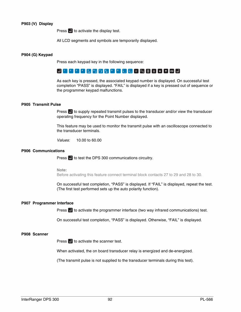
InterRanger DPS 300 92 PL-566
P903 (V) Display
Press to activate the display test.
All LCD segments and symbols are temporarily displayed.
P904 (G) Keypad
Press each keypad key in the following sequence:
As each key is pressed, the associated keypad number is displayed. On successful testcompletion “PASS” is displayed. “FAIL” is displayed if a key is pressed out of sequence orthe programmer keypad malfunctions.
P905 Transmit Pulse
Press to supply repeated transmit pulses to the transducer and/or view the transduceroperating frequency for the Point Number displayed.
This feature may be used to monitor the transmit pulse with an oscilloscope connected tothe transducer terminals.
Values: 10.00 to 60.00
P906 Communications
Press to test the DPS 300 communications circuitry.
Note:Before activating this feature connect terminal block contacts 27 to 29 and 28 to 30.
On successful test completion, “PASS” is displayed. If “FAIL” is displayed, repeat the test.(The first test performed sets up the auto polarity function).
P907 Programmer Interface
Press to activate the programmer interface (two way infrared communications) test.
On successful test completion, “PASS” is displayed. Otherwise, “FAIL” is displayed.
P908 Scanner
Press to activate the scanner test.
When activated, the on board transducer relay is energized and de-energized.
(The transmit pulse is not supplied to the transducer terminals during this test).

PL-566 93 InterRanger DPS 300
P910 Relay
Access this parameter to display the current state of the specified relay.
Press to alter the relay state (energized / de-energized) or enter the valuecorresponding to the specific relay state desired.
Values:
0 = de-energized1 = energized
P911 mA Output Value
Access this parameter to display the current value of the specified mA output.
Additionally, this feature may be used to enter a desired value. The mA output isimmediately forced to the value entered, regardless of any restrictions programmed.
Values: 0.000 to 25.00
P912 Transducer Temperature
Access this parameter to display the temperature in °C (as monitored by the connectedtransducer). “Err” or “OPEn” is displayed if the transducer is not properly connected.
Values: -50 to 150
P913 Sensor Temperature
Access this parameter to display the temperature in °C (as monitored by the connectedtemperature sensor). “OPEn” is displayed if a TS-3 is not connected.
Values: -50 to 150
Measurement Parameters (P920 to P923)
Use these parameters to verify Application Parameter programming, when performing adynamic level test over at least 2 empty/fill cycles for each clarifier is impractical.
Access the following parameters to take an ultrasonic measurement and automatically:
• display the corresponding Reading in the Parameter Value field.
• set the mA output value accordingly.
• set the relay status accordingly.
• transmit the corresponding point data.
Note:If measurements or simulation are desired, however DPS 300 operation has not beenverified, disable all associated process control equipment before accessing the followingparameters.

InterRanger DPS 300 94 PL-566
To take an ultrasonic measurement, access one of the following parameters and...
1. Press (repeat 5 times to overcome Echo Lock, P711).
Alternatively, press to simulate a rising and falling material level. During thesimulation, the DPS 300 will operate as though the sludge level was repeatedly cyclingfrom full to empty to full, and so on, at a rate of 1% of Span (P007) per second. See Lock(P000) to activate control relays during simulation.
The simulation starts at level = 0, unless a specific level value was entered beforehand.
2. Press to switch to the rising (or for the emptying) simulation as required. Holdingthe key increases (or decreases) the simulated rate of rise (or fall), to 4% of Span persecond.
3. Press to end the simulation, when desired.
During a measurement or simulation, the DPS 300 display responds as though in theRUN mode, however the value displayed in the Reading field is affected by theMeasurement Parameter selected, and the material level is displayed in the AuxiliaryReading field.
P920 Reading Measurement
The Reading corresponds to all associated programming.
P921 Material Measurement
The Reading corresponds to the distance between Empty (P006) and the sludge level.
P922 Space Measurement
The Reading corresponds to the distance between the sludge level and Span (P007).
P923 Distance Measurement
The Reading corresponds to the distance between the sludge level and the transducerface.
P924 Volume Measurement
The Reading corresponds to the volume calculation in percent of Max Volume (P051). Press as required to display in Max Volume units.
P927 Distance Percent
Same as P923, plus alternate reading in % press

PL-566 95 InterRanger DPS 300
Master Reset (P999)
P999 Master Reset
A Global Master Reset (reset all parameters to preset values) should be performed:
• to clear all operator programming from memory.
• after replacing the DPS 300 EPROM with a different software revision number.
Note:Following a Global Master Reset, complete reprogramming is required.
A Point Number Master Reset (reset the non-global parameters of the displayed PointNumber to preset values) should be performed if a Point Number is being reassigned to adifferent clarifier.
To perform a Global Master Reset:
1. With the Parameter Number field accessed, key in 999,
2. With the Point Number field accessed, key in 00,
3. Press “C.ALL” is displayed until the reset is complete.
To perform a Point Number Master Reset:
1. With the Parameter Number field accessed, key in 999,
2. With the Point Number field accessed, key in the Point Number to be reset (1, or 2)
3. Press , “C.ALL” is displayed until the reset is complete.

InterRanger DPS 300 96 PL-566
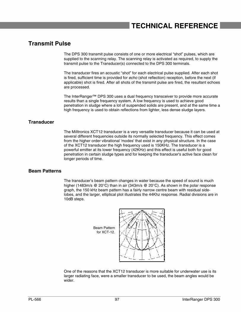
PL-566 97 InterRanger DPS 300
TECHNICAL REFERENCE
Transmit Pulse
The DPS 300 transmit pulse consists of one or more electrical “shot” pulses, which aresupplied to the scanning relay. The scanning relay is activated as required, to supply thetransmit pulse to the Transducer(s) connected to the DPS 300 terminals.
The transducer fires an acoustic “shot” for each electrical pulse supplied. After each shotis fired, sufficient time is provided for echo (shot reflection) reception, before the next (ifapplicable) shot is fired. After all shots of the transmit pulse are fired, the resultant echoesare processed.
The InterRanger™ DPS 300 uses a dual frequency transceiver to provide more accurateresults than a single frequency system. A low frequency is used to achieve goodpenetration in sludge where a lot of suspended solids are present, and at the same time ahigh frequency is used to obtain reflections from lighter, less dense sludge layers.
Transducer
The Milltronics XCT12 transducer is a very versatile transducer because it can be used atseveral different frequencies outside its normally selected frequency. This effect comesfrom the higher order vibrational 'modes' that exist in any physical structure. In the caseof the XCT12 transducer the high frequency used is 150KHz. The transducer is apowerful emitter at its lower frequency (42KHz) and this effect is useful both for goodpenetration in certain sludge types and for keeping the transducer's active face clean forlonger periods of time.
Beam Patterns
The transducer’s beam pattern changes in water because the speed of sound is muchhigher (1483m/s @ 20°C) than in air (343m/s @ 20°C). As shown in the polar responsegraph, the 150 kHz beam pattern has a fairly narrow centre beam with residual side-lobes, and the larger, elliptical plot illustrates the 44Khz response. Radial divisions are in10dB steps.
One of the reasons that the XCT12 transducer is more suitable for underwater use is itslarger radiating face, were a smaller transducer to be used, the beam angles would bewider.
Beam Patternfor XCT-12.
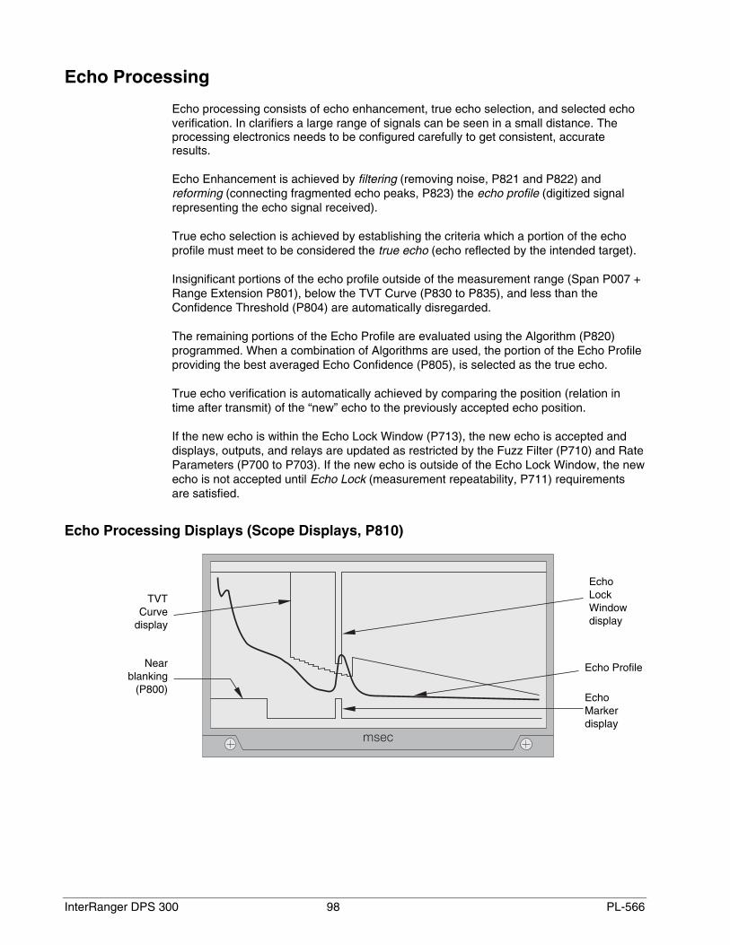
InterRanger DPS 300 98 PL-566
Echo Processing
Echo processing consists of echo enhancement, true echo selection, and selected echoverification. In clarifiers a large range of signals can be seen in a small distance. Theprocessing electronics needs to be configured carefully to get consistent, accurateresults.
Echo Enhancement is achieved by filtering (removing noise, P821 and P822) andreforming (connecting fragmented echo peaks, P823) the echo profile (digitized signalrepresenting the echo signal received).
True echo selection is achieved by establishing the criteria which a portion of the echoprofile must meet to be considered the true echo (echo reflected by the intended target).
Insignificant portions of the echo profile outside of the measurement range (Span P007 +Range Extension P801), below the TVT Curve (P830 to P835), and less than theConfidence Threshold (P804) are automatically disregarded.
The remaining portions of the Echo Profile are evaluated using the Algorithm (P820)programmed. When a combination of Algorithms are used, the portion of the Echo Profileproviding the best averaged Echo Confidence (P805), is selected as the true echo.
True echo verification is automatically achieved by comparing the position (relation intime after transmit) of the “new” echo to the previously accepted echo position.
If the new echo is within the Echo Lock Window (P713), the new echo is accepted anddisplays, outputs, and relays are updated as restricted by the Fuzz Filter (P710) and RateParameters (P700 to P703). If the new echo is outside of the Echo Lock Window, the newecho is not accepted until Echo Lock (measurement repeatability, P711) requirementsare satisfied.
Echo Processing Displays (Scope Displays, P810)
TVTCurve
display
Nearblanking
(P800)
EchoLockWindowdisplay
EchoMarkerdisplay
Echo Profile

PL-566 99 InterRanger DPS 300
Distance Calculation
To calculate the transducer to sludge distance, the sound velocity (P653) is multiplied bythe acoustic transmission to reception time period.
Distance = Sound Velocity x Time2
The Reading Value displayed is the result of performing any additional modification to thecalculated distance (Operation P001, Units P005, Volume Conversion, P050 to P054,Reading Value, P060 to P063.)
Sound Velocity
The velocity of sound in water is affected by its temperature. The DPS 300 is preset foroperation in water at 20°C (68°F). Unless altered, the sound velocity used for thedistance calculation is 1483 m/s (4864 ft/s).
The XCT-12 transducer incorporates a temperature sensing element which providestemperature reporting to the DPS 300 for automatic compensation of sound velocity.
Also, if the temperature varies between the transducer face and the sludge surface, a TS-3 temperature sensor, mounted in between can be used in combination with thetransducer. Then when Temp Source, (P660) is set for “both”, the transducer and TS-3temperature measurements are averaged.
Scanning
When echo processing is complete, (if two clarifiers are monitored) the scanning relaychanges state to supply the transmit pulse to the transducer of the other clarifier after theScan Delay (P727).

InterRanger DPS 300 100 PL-566
Volume Calculation
The DPS 300 provides a variety of volume calculation features (P050 to P055).
If the clarifier to be monitored does not match any of the 8 preset shape calculations, aUniversal Volume calculation may be used. Use the level/volume graph or chart providedby the clarifier fabricator (or create one based on the clarifier dimensions).
From this graph, determine which Universal Volume calculation will provide the bestresults, and select the level vs. volume breakpoints to be entered (32 max.). Generally,the more breakpoints entered, the greater the volume calculation accuracy.
Universal, Linear (P050 = 9)
This volume calculation creates a piece-wise linear approximation of the level/volumecurve. This option provides best results if the curve has sharp angles joining relativelylinear sections.
Enter a Level Breakpoint at each point where the level/volume curve bends sharply (2minimum).
For combination curves (mostly linear but include 1 or more arcs), ensure numerousbreakpoints are entered along the arc, for best volume calculation accuracy.
Universal, Curved (P050 = 10)
This volume calculation creates a cubic spline approximation of the level/volume curve.This option provides best results if the curve is non-linear, and there are no sharp angles.
Select at least enough breakpoints from the curve to satisfy the following:
• 2 breakpoints very near the minimum level
• 1 breakpoint at the tangent points of each arc
• 1 breakpoint at each arc apex
• 2 breakpoints very near the maximum level
For combination curves, ensure at least 2 breakpoints are entered immediately beforeand after any sharp angle (as well as 1 breakpoint exactly at the angle) on the curve.
clarifier linear calculation
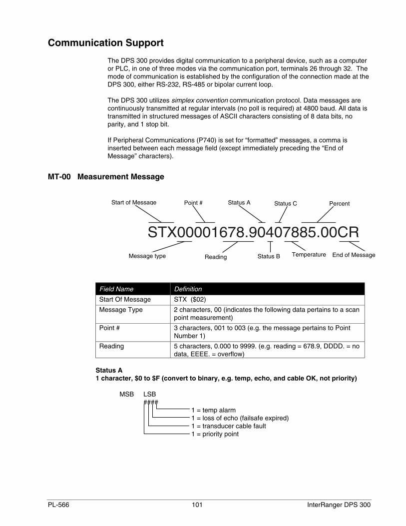
PL-566 101 InterRanger DPS 300
Communication Support
The DPS 300 provides digital communication to a peripheral device, such as a computeror PLC, in one of three modes via the communication port, terminals 26 through 32. Themode of communication is established by the configuration of the connection made at theDPS 300, either RS-232, RS-485 or bipolar current loop.
The DPS 300 utilizes simplex convention communication protocol. Data messages arecontinuously transmitted at regular intervals (no poll is required) at 4800 baud. All data istransmitted in structured messages of ASCII characters consisting of 8 data bits, noparity, and 1 stop bit.
If Peripheral Communications (P740) is set for “formatted” messages, a comma isinserted between each message field (except immediately preceding the “End ofMessage” characters).
MT-00 Measurement Message
Field Name Definition
Start Of Message STX ($02)
Message Type 2 characters, 00 (indicates the following data pertains to a scanpoint measurement)
Point # 3 characters, 001 to 003 (e.g. the message pertains to PointNumber 1)
Reading 5 characters, 0.000 to 9999. (e.g. reading = 678.9, DDDD. = nodata, EEEE. = overflow)
Status A1 character, $0 to $F (convert to binary, e.g. temp, echo, and cable OK, not priority)
MSB LSB####
1 = temp alarm1 = loss of echo (failsafe expired)1 = transducer cable fault1 = priority point
Start of Message Point # Status A Status C Percent
End of MessageTemperatureStatus BReadingMessage type

InterRanger DPS 300 102 PL-566
Status B1 character, $0 to $F (convert to binary, e.g. scan point is in high alarm)
MSB LSB####
1 = low low alarm1 = low alarm1 = high alarm1 = high high alarm
Status C1 character, $0 to $F (convert to binary, e.g. scan point is not in rate or band alarm)
MSB LSB####
1 = rate alarm 21 = rate alarm 11 = band alarm 11 = band alarm 2
Field Name Definition
Temp 2 characters, $32 to $FA (convert to decimal and subtract 100,e.g. temperature = 20 °C)
Percent 5 characters, 00.00 to 9999. (e.g. current level = 85.00% ofspan, EEEE. = field overflow)
End Of Message CR ($0D)
MT-01 Hold Message
e.g.
Field Name Definition
Start Of Message STX ($02)Message Type 2 characters, 01 (indicates the DPS 300 was removed from the
RUN mode)End Of Message CR ($0D)
Start of Message End of MessageMessage type

PL-566 103 InterRanger DPS 300
MT-03 POINT NOT SCANNED
e.g.
Field Name Definition
Start Of Message STX ($02)Message Type 2 characters, 03 (indicates the Point Number is not in
service)Point # 3 characters, 001 to 003 (e.g. Point Number 1)End Of Message CR ($0D)
Start of Message Point #
End of MessageMessage type

InterRanger DPS 300 104 PL-566
PL-566 105 InterRanger DPS 300
MAINTENANCE The DPS 300 should require little maintenance, though good housekeeping practices inand around the area of the enclosure are recommended.
Wipe out the area of the enclosure lid docking bay recess with a clean dry cloth (ifnecessary) before installing the programmer.
Inspect the transducer regularly. By nature of its ultrasonic emissions, the face has selfcleaning properties. However, scum and algae can build up on the sides, and if notremoved, can encroach onto the face, adversely affecting performance.
Depending on the application, the transducer face may require cleaning to maintain anacceptable performance level.

InterRanger DPS 300 106 PL-566
PL-566 107 InterRanger DPS 300
TROUBLESHOOTING GUIDE
Measurement Difficulties
If a measurement difficulty occurs for greater than the Failsafe Timer (P070) setting,“LOE” is flashed alternately with the Reading display. Under certain conditions, ameasurement difficulty may cause the DPS 300 to “lock on” to a false echo and report afixed or wrong reading.
Flashing “LOE” Display
If “LOE” is displayed, ensure that the:
1. Sludge surface is within the maximum range of the transducer (see Transducer on page6).
2. Transducer is located properly (see Application Planning on page 15).
To display Echo Confidence in the RUN mode press and hold for 4 seconds (FailsafeTime Left changes to the Short : Long Confidence display).
To display Echo Confidence in the program mode, access the Echo Confidence (P805)parameter. To update the value displayed after each aiming adjustment press (5times or more to verify stability).
Increase the Failsafe Timer (P070) value, if failsafe operation will not be compromised bythe larger value.
LOE may be an indication that the sludge is at a level exposing the clarifier at that point. The slope bottom of the clarifier may be reflecting the echo away from the transducer. Move the transducer to a location where there is still a sludge blanket or limit the sludgelow level.
If a discernible echo from the sludge is observed, reduce the Confidence Threshold(P804) while taking new measurements (in the RUN or program mode).
Fixed Reading
If the Reading is a fixed value, regardless of the transducer to sludge distance, ensurethe:
1. Transducer sound beam is free from obstruction.
2. Sludge level is not within the Transducers' nearest measurable distance.
If the obstruction cannot be removed or avoided, the DPS 300 TVT (Time VaryingThreshold) Curve must be modified to reduce the Echo Confidence derived from thesound reflected by the obstruction. (See ENHANCEMENT PARAMETERS / ScopeDisplays, P810 and TVT Shaper, P832).

InterRanger DPS 300 108 PL-566
If the fixed Reading represents a minimal distance from the transducer face, the conditionmay be caused by a sound beam obstruction (check for this first), but could also be dueto other factors.
If the sludge surface is within the Transducers' nearest distance, limit the high level of thesludge blanket.
If the preceding remedies have not produced satisfactory results, the false echo has to beignored. Extend Near Blanking (P800) to a distance (from the transducer face) to justbeyond the distance represented by the Reading. This also increases the nearestdistance the sludge may come within the transducer face and still be detected.
Connect an oscilloscope to the DPS 300, (see ENHANCEMENT PARAMETERS / ScopeDisplays, P810). Adjust the TVT Start Min (P833), TVT Start Duration (P834), and TVTSlope Min (P835) slightly, to raise the TVT curve in the area of the false echo.
Continue making minor TVT Curve adjustments and taking new measurements whileobserving the Echo Marker position until the Echo Lock Window repeatedly locks onto thetrue echo. Verify the false echo is still ignored, regardless of the sludge level, or empty/fillactivity.
Wrong Reading
If the Reading is erratic, or jumps to some incorrect value periodically, ensure the:
1. Sludge level is not beyond the transducers maximum range.
2. Material (P002) value matches the type of sludge monitored.
If the periodic incorrect value is always the same, see Fixed Reading. If the incorrectvalue seems to be random, verify the material surface to transducer distance is less thanthe Empty value entered plus 20%. If the sludge monitored is outside this distance,increase Range Extension (P801) as required.
Variable Reading
If the material reading is “jumping” from the correct level, try the following techniques:
• Set the Long Shot Number (P841) to a larger value to average more shots to get ameasurement
• Set Echo Lock (P711) to “max verification” (response to sludge level changes may beslowed somewhat).
• Increase the Echo Lock Sampling (P712) and / or decrease the Echo Lock Window(P713) to ignore erroneous readings
• Decrease the Long Shot Width (P845) to keep the different echos in the profile distinct
Access the Noise (P807) parameter. If the peak value jumps wildly, verify the transducercable shields are connected to the DPS 300 shield terminals and not to groundelsewhere.
If the DPS 300 is mounted in proximity to (or transducer cables run near those of) anotherultrasonic level monitor. If they do, see Level System Sync (P726).
PL-566 109 InterRanger DPS 300
Temporarily disable nearby SCR control drives, high voltage or current contactors. If thecondition disappears, move the DPS 300 to another location.
Increase the Confidence Threshold (small amounts at a time) while observing the results.If performance is not improved return the Confidence Threshold to the preset value.
Connect an oscilloscope to the DPS 300, (see ENHANCEMENT PARAMETERS / ScopeDisplays, P810). While monitoring the Echo Marker, select the Algorithm (P820) bestsuited to the clarifier.
If the “Area” algorithm is used and narrow noise spikes are evident on the (long shot)Echo Profile, turn the Spike Filter (P821) on and/or widen the Narrow Echo Filter (P822).Also, if the true echo has jagged peaks, use Reform Echo (P823).
Should a stable measurement still not be attainable, contact Milltronics or your localdistributor.

InterRanger DPS 300 110 PL-566
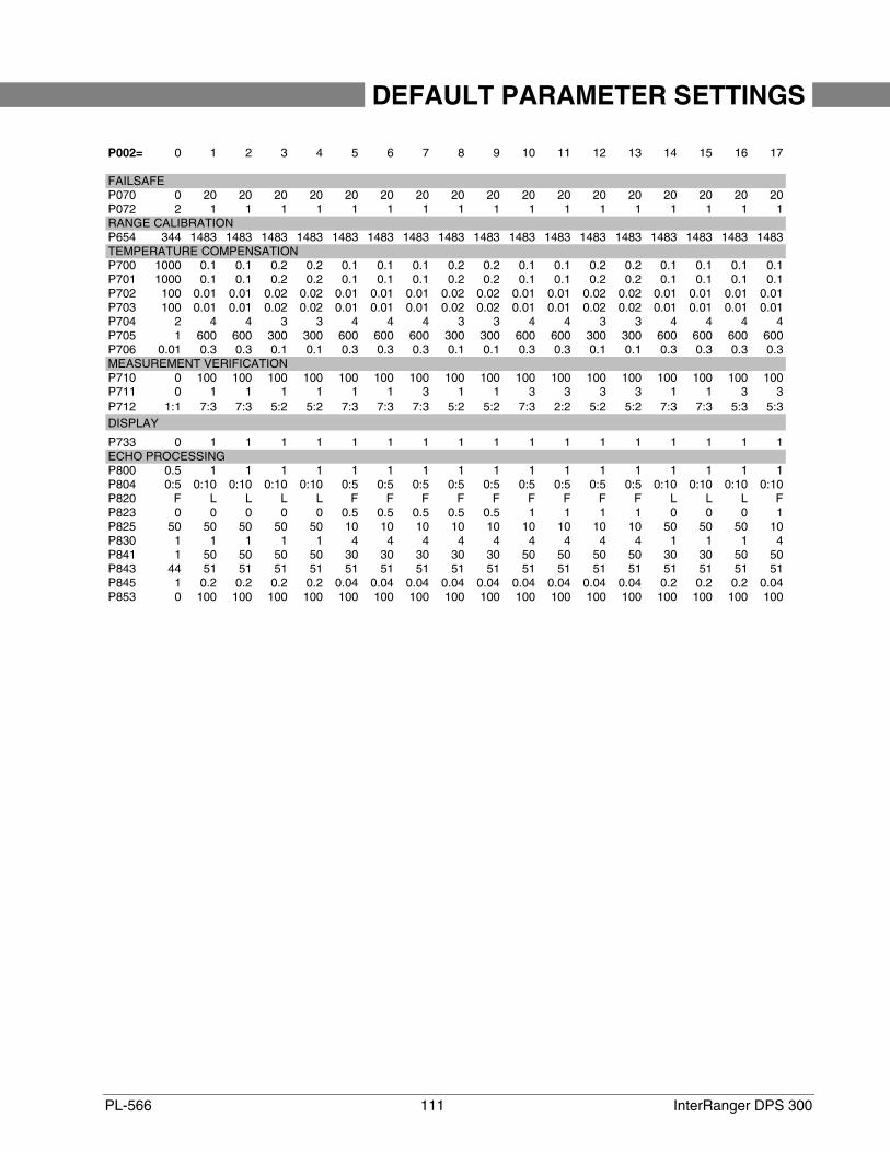
PL-566 111 InterRanger DPS 300
DEFAULT PARAMETER SETTINGS
P002= 0 1 2 3 4 5 6 7 8 9 10 11 12 13 14 15 16 17
FAILSAFEP070 0 20 20 20 20 20 20 20 20 20 20 20 20 20 20 20 20 20P072 2 1 1 1 1 1 1 1 1 1 1 1 1 1 1 1 1 1RANGE CALIBRATIONP654 344 1483 1483 1483 1483 1483 1483 1483 1483 1483 1483 1483 1483 1483 1483 1483 1483 1483TEMPERATURE COMPENSATIONP700 1000 0.1 0.1 0.2 0.2 0.1 0.1 0.1 0.2 0.2 0.1 0.1 0.2 0.2 0.1 0.1 0.1 0.1P701 1000 0.1 0.1 0.2 0.2 0.1 0.1 0.1 0.2 0.2 0.1 0.1 0.2 0.2 0.1 0.1 0.1 0.1P702 100 0.01 0.01 0.02 0.02 0.01 0.01 0.01 0.02 0.02 0.01 0.01 0.02 0.02 0.01 0.01 0.01 0.01P703 100 0.01 0.01 0.02 0.02 0.01 0.01 0.01 0.02 0.02 0.01 0.01 0.02 0.02 0.01 0.01 0.01 0.01P704 2 4 4 3 3 4 4 4 3 3 4 4 3 3 4 4 4 4P705 1 600 600 300 300 600 600 600 300 300 600 600 300 300 600 600 600 600P706 0.01 0.3 0.3 0.1 0.1 0.3 0.3 0.3 0.1 0.1 0.3 0.3 0.1 0.1 0.3 0.3 0.3 0.3MEASUREMENT VERIFICATIONP710 0 100 100 100 100 100 100 100 100 100 100 100 100 100 100 100 100 100P711 0 1 1 1 1 1 1 3 1 1 3 3 3 3 1 1 3 3P712 1:1 7:3 7:3 5:2 5:2 7:3 7:3 7:3 5:2 5:2 7:3 2:2 5:2 5:2 7:3 7:3 5:3 5:3DISPLAY
P733 0 1 1 1 1 1 1 1 1 1 1 1 1 1 1 1 1 1ECHO PROCESSINGP800 0.5 1 1 1 1 1 1 1 1 1 1 1 1 1 1 1 1 1P804 0:5 0:10 0:10 0:10 0:10 0:5 0:5 0:5 0:5 0:5 0:5 0:5 0:5 0:5 0:10 0:10 0:10 0:10P820 F L L L L F F F F F F F F F L L L FP823 0 0 0 0 0 0.5 0.5 0.5 0.5 0.5 1 1 1 1 0 0 0 1P825 50 50 50 50 50 10 10 10 10 10 10 10 10 10 50 50 50 10P830 1 1 1 1 1 4 4 4 4 4 4 4 4 4 1 1 1 4P841 1 50 50 50 50 30 30 30 30 30 50 50 50 50 30 30 50 50P843 44 51 51 51 51 51 51 51 51 51 51 51 51 51 51 51 51 51P845 1 0.2 0.2 0.2 0.2 0.04 0.04 0.04 0.04 0.04 0.04 0.04 0.04 0.04 0.2 0.2 0.2 0.04P853 0 100 100 100 100 100 100 100 100 100 100 100 100 100 100 100 100 100

InterRanger DPS 300 112 PL-566

PL-566 113 InterRanger DPS 300
PROGRAMMING CHARTS
Programming Chart 1
PARAMETER ALTERED VALUES FOR POINT #’S
# NAME 1 2 3
SECURITY
P000 Lock (G)
QUICK START
P001 Operation
P002 Material
P005 (G) Units
P006 Empty
P007 Span
VOLUME
P050 Tank Shape
P051 Max Volume
P052 Tank Dimension A
P053 Tank Dimension L
P054 Level Breakpoints record values on a separate sheet
P055 Breakpoint Volumes record values on a separate sheet
READING VALUE
P060 Decimal Position
P061 Convert Reading
P062 Offset Reading
FAILSAFE
P070 Failsafe Timer
P071 Failsafe Material Level
P072 Failsafe Level Advance
RELAYS
P100 (G) Relay Set Up
P101 High Alarm
P102 Low Alarm
P103 High High Alarm
P104 Low Low Alarm
P110 Relay Allocation
P111 Relay Function
P112 Relay A Setpoint
P113 Relay B Setpoint
P116 Bound Alarm Deadband
P129 Relay Failsafe
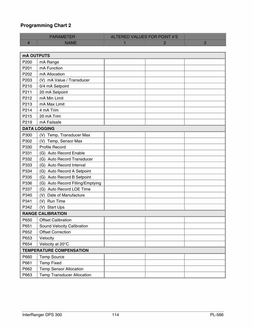
InterRanger DPS 300 114 PL-566
Programming Chart 2
PARAMETER ALTERED VALUES FOR POINT #’S
# NAME 1 2 3
mA OUTPUTS
P200 mA Range
P201 mA Function
P202 mA Allocation
P203 (V) mA Value / Transducer
P210 0/4 mA Setpoint
P211 20 mA Setpoint
P212 mA Min Limit
P213 mA Max Limit
P214 4 mA Trim
P215 20 mA Trim
P219 mA Failsafe
DATA LOGGING
P300 (V) Temp, Transducer Max
P302 (V) Temp, Sensor Max
P330 Profile Record
P331 (G) Auto Record Enable
P332 (G) Auto Record Transducer
P333 (G) Auto Record Interval
P334 (G) Auto Record A Setpoint
P335 (G) Auto Record B Setpoint
P336 (G) Auto Record Filling/Emptying
P337 (G) Auto Record LOE Time
P340 (V) Date of Manufacture
P341 (V) Run Time
P342 (V) Start Ups
RANGE CALIBRATION
P650 Offset Calibration
P651 Sound Velocity Calibration
P652 Offset Correction
P653 Velocity
P654 Velocity at 20°C
TEMPERATURE COMPENSATION
P660 Temp Source
P661 Temp Fixed
P662 Temp Sensor Allocation
P663 Temp Transducer Allocation
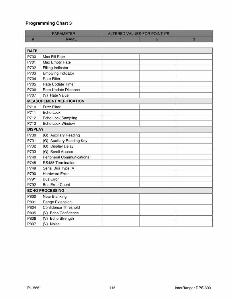
PL-566 115 InterRanger DPS 300
Programming Chart 3
PARAMETER ALTERED VALUES FOR POINT #’S
# NAME 1 2 3
RATE
P700 Max Fill Rate
P701 Max Empty Rate
P702 Filling Indicator
P703 Emptying Indicator
P704 Rate Filter
P705 Rate Update Time
P706 Rate Update Distance
P707 (V) Rate Value
MEASUREMENT VERIFICATION
P710 Fuzz Filter
P711 Echo Lock
P712 Echo Lock Sampling
P713 Echo Lock Window
DISPLAY
P730 (G) Auxiliary Reading
P731 (G) Auxiliary Reading Key
P732 (G) Display Delay
P733 (G) Scroll Access
P740 Peripheral Communications
P748 RS485 Termination
P749 Serial Bus Type (V)
P790 Hardware Error
P791 Bus Error
P792 Bus Error Count
ECHO PROCESSING
P800 Near Blanking
P801 Range Extension
P804 Confidence Threshold
P805 (V) Echo Confidence
P806 (V) Echo Strength
P807 (V) Noise
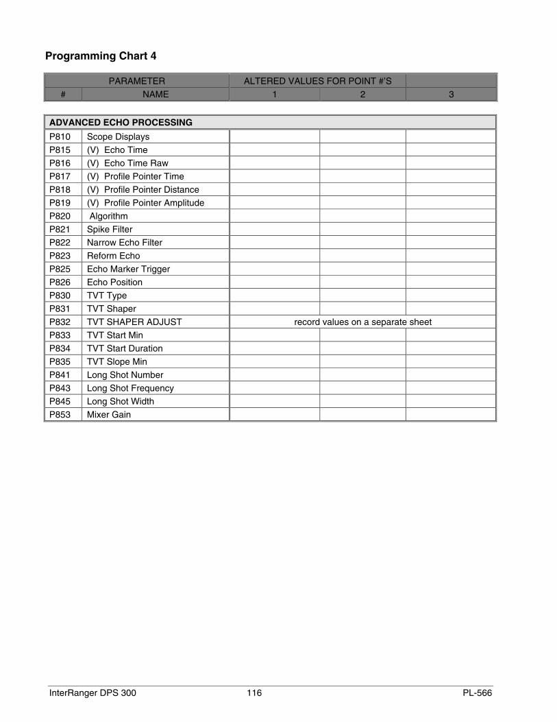
InterRanger DPS 300 116 PL-566
Programming Chart 4
PARAMETER ALTERED VALUES FOR POINT #’S
# NAME 1 2 3
ADVANCED ECHO PROCESSING
P810 Scope Displays
P815 (V) Echo Time
P816 (V) Echo Time Raw
P817 (V) Profile Pointer Time
P818 (V) Profile Pointer Distance
P819 (V) Profile Pointer Amplitude
P820 Algorithm
P821 Spike Filter
P822 Narrow Echo Filter
P823 Reform Echo
P825 Echo Marker Trigger
P826 Echo Position
P830 TVT Type
P831 TVT Shaper
P832 TVT SHAPER ADJUST record values on a separate sheet
P833 TVT Start Min
P834 TVT Start Duration
P835 TVT Slope Min
P841 Long Shot Number
P843 Long Shot Frequency
P845 Long Shot Width
P853 Mixer Gain

Siemens Milltronics Process Instruments Inc.1954Technology Drive, P.O. Box 4225Peterborough, ON.Canada K9J 7B1Tel: (705) 745-2431 Fax: (705) 741-0466www.milltronics.com Printed in Canada
c
*7ml19981bc01* Rev. 1.0


