INTERREG IV(A) CHANNEL PROGRAMME FOSTERING LONG TERM INITIATIVES IN PORTS (FLIP) TOR BAY HARBOUR AUTHORITY FLIP Study 2- Quay Resistance - Corrosion Survey & feasibility study for Cathodic Protection in Channel ports (case study: Torquay Harbour Structures) for sharing knowledge and best practice with FLIP partners.
Transcript
INTERREG IV(A) CHANNEL PROGRAMME FOSTERING LONG TERM INITIATIVES IN
PORTS (FLIP) TOR BAY HARBOUR AUTHORITY
FLIP Study 2- Quay Resistance -
Corrosion Survey & feasibility study for
Cathodic Protection in Channel ports
(case study: Torquay Harbour Structures)
for sharing knowledge and best practice
with FLIP partners.
EU Interreg IVa Channel Programme FLIP project no.5675
Torbay Council:- ACTION (2.2.9) Engineering and Technical studies for Torquay,
Paignton & Brixham quays and corrosion resistance.
Study 2. Quay Resistance - Corrosion Survey, Torquay Harbour Structures
Introduction
The study is intended to address ongoing protection to existing unprotected steel and steel reinforced
structures at Torquay Harbour and forms one of three inter-related studies commissioned by Torbay
Council to examine the need to protect the infrastructure of the Tor Bay harbours and assessing their
value.
The studies are part funded under the EU Interreg IVa Channel Programme, FLIP (Fostering Long Term
Initiatives in Ports) project no.5675.The results from the studies provide an opportunity to share
knowledge with other FLIP port partners, to learn of common problems and identify technical
solutions. The FLIP project also disseminates the study results to small and medium sized ports and
harbours in the Channel area via the project website: http://www.flip-ports.eu/
In four of the six cases where Cathodic protection (CP) is feasible, galvanic anodes are recommended
to be installed in the near future. Of the remaining two cases, CP is not considered to be required at
the present time in one, and is not considered suitable in the other. An alternative solution is proposed
for the latter case.
In the remaining case where CP is not feasible, but where unprotected steel is present, at the
boardwalk sub frame at Princess Pier, suitable repair informed by truss load testing at the pier head
and followed by application of a protective coating system is recommended to be undertaken in the
near future.
At the pier head however, given the combination of the condition of the steelwork support to the
banjo, the cross ties to the circular piles, and the timber deck it may be more economically viable to
reduce the extent of the pier head structure, the majority of which is currently closed due not least to
the significantly defective condition of timber. For the purpose of informing some judgement on the
economy of options an estimate of cost of steelwork repair and coating will follow in due course.
Contents
1. Scope
2. Cathodic Protection (CP)
3. Princess Pier steelwork sub frame to boardwalk
3.1 Convention 3.2 Steel elements
3.2.1 Piles and connecting members, seaward side of the pier, chainage 2-147 3.2.2 Galvanised sub frame members ch. 28-152 3.2.3 Steel truss work concrete encased propping chainages 1-28
4. Conclusions and Recommendations
4.1 Cathodic Protection (CP) 4.2 Princess Pier steel sub frame to boardwalk
4.2.1 Piles and connecting members, seaward side of the pier, chainage 2-147 4.2.2 Galvanised sub frame members ch. 28-152 4.2.3 Steel truss work concrete encased propping chainages 1-28
4.3 Protective coating 4.4 Economic consideration
5. Photographs
Appendix A Torquay Harbour – Various Structures: Feasibility Study for Cathodic Protection 261/REP/01.
Corrosion Prevention March 2015
Appendix B Archive Drawings - Princess Pier
B1/1759/1 Princess Pier ‘Islander’ Area Structural Survey – Gen Arrangement Existing
Steelwork and Layouts at Deck Level and at Top of Sea Wall 1975
B1/1934/8 Princess Pier Reconstruction – Gen Arrangement of New Steel Supporting Deck
and Shelter 1978
B1/1934/9 Princess Pier Reconstruction – Typ Details of New Steelwork Supporting Deck and
Shelter 1978
B1/625/5 – Details of Existing Girders, Princess Pier 1968
1. Scope
This report is intended to address ongoing protection to existing unprotected steel and steel reinforced
harbour structures at Torquay Harbour.
Thus the potential for the installation of cathodic protection (CP) is examined – through a commissioned
specialist’s submission – and In line with the remit of ‘corrosion surveys’ described in the FLIP appendix
protective works to other steel elements of harbour structures not within the scope of CP are additionally
included.
Structures considered, and their steel elements are:
A. Princess Pier
steel box and circular piles
steel- framed support to the timber boardwalk
concrete encased propping to the suspended pier head widening B. Fish Quay
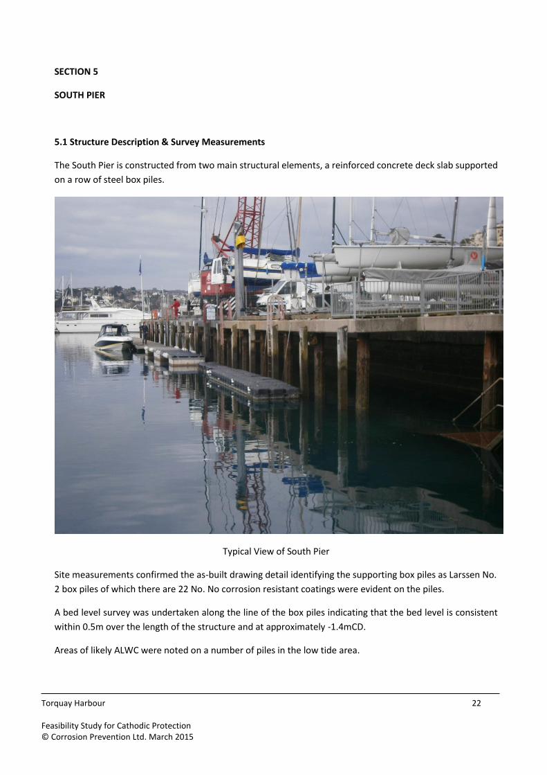
sheet piled quay wall C. South Pier
reinforced concrete (RC) slab extension to original masonry structure
driven steel box piles.
CP and non-CP solutions for the three structures, along with their design life expectancy and a guide range of
costs of detailed design and build/install are provided.
2. Cathodic Protection (CP)
CP can only be considered where structural steel exists within an electrolytic medium such as seawater (up to
around mid-tide), or concrete encasement. The appended report thus considers structural elements meeting
these criteria:
A. Princess Pier
steel box and circular piles
concrete encased propping to the suspended pier head widening B. Fish Quay
sheet piled quay wall C. South Pier
reinforced concrete (RC) slab extension to original masonry structure
driven steel box piles.
The report identifies viable CP solutions with cost estimates to all except the concrete encased propping at
Princess Pier, which may otherwise be protected by a coating system.
3. Princess Pier steelwork sub frame to boardwalk
3.1 Convention
Reference chainages and notations arise from, and align with those appearing in appended General
Arrangement drawings B1/1759/1 and B1/1934/8.
3.2 Steel elements
The steel elements below the timber boardwalk, indicated in arrangement drawings B1/1759/1 and
B1/1934/8 may be classified thus:
piles and their connecting members on the seaward side of the pier, supporting the castellated beams to the deck suspended over water, chainage 2-147. Piles double up width wise and are braced with tie rods below the pier head widening.
galvanised members installed 1970s through chainages 28-152
original/older steel truss work (anecdotally dated to 1950s/60s) and concrete encased propping below the widened pier head, in archive drawings is variously termed the ‘Banjo’ and ‘Islander’, chainages 1-28
3.2.1 Piles and connecting members, seaward side of the pier, chainage 2-147
Accelerated Low Water Corrosion (ALWC) is likely hidden by extensive marine growth to lower areas. As
recognised in the appended CP specific report these elements are recommended to be protected by CP, up to
mid tide.
Piles supporting the seaward side of the Pier were analysed by sample for section thickness. The newer piles
supporting the castellated beams were measured to be typically 15.5mm, aligning with the 14mm thickness
expected of Frodingham no 4 specified in archive drawings, whilst the thickness of the older ‘10” screw piles’
piles supporting the banjo structure was measured to average around 18mm. Such a section thickness is at
the heaviest end of circular steel sections currently available.
The 1½“ tie rod bracing to the screw piles supporting the Banjo structure is recognised by this and other
reports to be in such a deteriorated corroded condition that it cannot be repaired.
3.2.2 Galvanised sub frame members ch. 28-152
In many localised areas the zinc coating to members in this framing has deteriorated such that corrosion of
the host steel has commenced.
3.2.3 Steel truss work and concrete encased propping chainages 1-28
The existing arrangement at this location has replacement galvanised steel truss work extending through
gridline D2-28 and through C1-5.
Similar to a Structural Investigation Report, R01121S001/B, by Pell Frischmann in 2007 a sample of section
sizes was measured on ‘original’ steel at truss D2/C1, an exposed but easily accessible location. The condition
of the steel truss appeared to be typical of the more weathered truss and bracing units. Section thicknesses
measured:
Top chord 10mm Diagonal strut 8mm Lower chord 5mm
Archive drawing B1/625/5 indicates that original steel was ½” i.e. 13mm.
4. Conclusions and Recommendations
4.1 Cathodic Protection (CP)
Galvanic anodes are recommended to be installed to the sheet piled wall of the Fish Quay structure, to the
box piles of the South Quay structure, and to the box and screw piles of the Princess Pier structure in the near
future.
CP is not currently considered to be required to the suspended slab at South Pier, and is not considered
suitable for the concrete encased props to the pier head at Princess Pier.
4.2 Princess Pier steel sub frame to boardwalk
4.2.1 Piles and connecting members, seaward side of the pier, chainage 2-147
Since CP would only be effective to piles up to mid tide a protective coating is recommended to be applied
above this level.
The 1½“ tie rod bracing to the screw piles supporting the Banjo structure is beyond repair and should be
replaced.
4.2.2 Galvanised sub frame members ch. 28-152
Corrosion has not resulted in significant section loss and the life of this framework may be extended with the
application of a protective coating
4.2.3 Steel truss work concrete encased propping chainages 1-28 The degree of loss of section of the steel sub frame was considered sufficient to preclude crowd loading (of
5kN/sq m) in a 2007 Pell Frischmann report (Princess Pier, Torquay - Structural Investigation Report
R01121S001/B). The detail of this judgement, a 2D finite element model has been requested, but has thus far
not been forthcoming. Meanwhile, approximate analysis and bending moment/lever arm inspection suggest
there is residual capacity after section loss in the sampled truss members to approach crowd load capacity.
Trusses comprising similar angle and flat steel elements on gridlines B and D appear to have been designed to
support the ‘Islander’ building lost to fire in 1974. Having been required to support both imposed loading and
that of the dead load of the Islander building the capacity required of these trusses would have been greater
than that required at the pier head in its current open arrangement.
Since the degree of corrosion to the trusses makes an absolute judgement somewhat difficult to make, load
testing may be a suitable method of gaining confidence in truss capacity.
Agreement may simultaneously be reached on a reasoned likely loading, where standard crowd loading might
otherwise be applied in calculations. Similar circumstances gave rise to a reduced pedestrian loading being
tested and agreed to be a sufficiently appropriate degree of verification for public safety, to the Grand Parade
balustrade, Bath, an account of which features in The Structural Engineer, May 2015.
Load testing would be proposed to be undertaken on a sample bay between trusses C24/C20, and truss
D24/D20, thereby including the truss considered by the 2007 Pell Frischmann report to have the highest
amount of section loss. Being located over the original masonry pier structure, this bay affords the opportunity
for easier installation of a crash deck immediately below the bay under test. For ease, loading may be applied
and increased in a controlled manner by the filling of highway water barriers over support beams spanning
between the two trusses under test.
4.3 Protective coating
With the confirmation that trusses remain adequate, or may be repaired or enhanced to be rendered
adequate, this report and that of Pell Frischmann 2007 recommend the application of a coatings system.
Maker Coating Systems Ltd (ref AS8317) has recommended the Corroless EPF system for application to the
whole of the boardwalk sub frame and the piles above mid tide. The system can offer a 25 year life expectancy.
Preparation by blast cleaning may be possible, but the proximity of the marine and leisure environments may
permit only needle gunned surface preparation with its better guarantee of waste material
retrieval/enclosure. This may have an impact on the life expectancy of the system.
A guide price is to be received from Ian Williams Ltd for the application of the Corroless System to the
steelwork as existing, and to include some steel repair works.
4.4 Economic consideration
The majority of the pier head has been closed for several years, largely due to the condition of the timber
decking presenting a significant failure hazard.
Given the combination of conditions of the steelwork support to the banjo, the diagonal bracing, and the
timber deck it may, against the cost of repair be more economically viable to reduce the extent of the
boardwalk pier structure at the pier head.
The 2007 Pell Frischmann report offered three options to address the condition of the pier head (2007
estimated budget uplifted by 5% per annum to 2015):
option works estimated cost (£m)
1 rebuild as existing, including the estimated cost of timber deck replacement
1,640
2 rebuild, but only to a width aligned with that of the pier neck, including the estimated cost of timber deck replacement over the reduced width
1,303
3 remove the pier head and install ramped access from the end of the pier neck on to the original concrete surface
531
Further, the same report offered an estimate for the demolition of the banjo and landing stage, similarly
updated here, to £270k
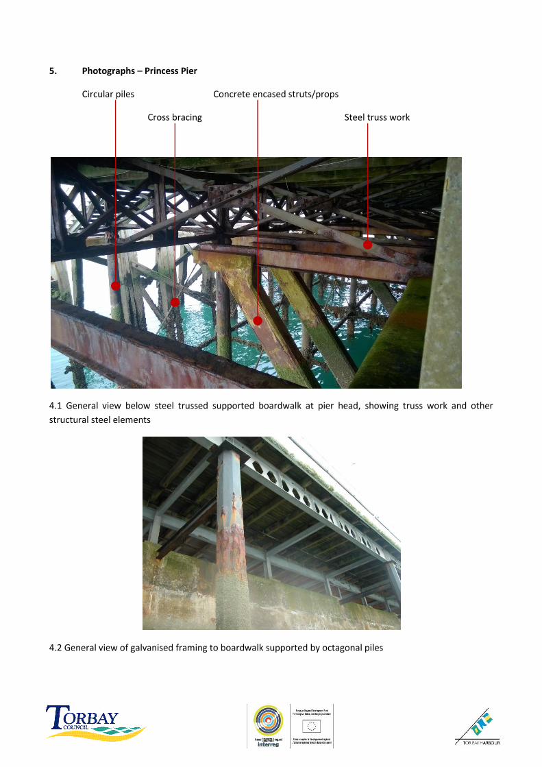
5. Photographs – Princess Pier
Circular piles Concrete encased struts/props
Cross bracing Steel truss work
4.1 General view below steel trussed supported boardwalk at pier head, showing truss work and other
structural steel elements
4.2 General view of galvanised framing to boardwalk supported by octagonal piles
Appendix A Torquay Harbour – Various Structures: Feasibility Study for Cathodic Protection
261/REP/01. Corrosion Prevention March 2015
Appendix B Archive Drawings
Princess Pier
B1/1759/1 Princess Pier ‘Islander’ Area Structural Survey – Gen Arrangement Existing
Steelwork and Layouts at Deck Level and at Top of Sea Wall 1975
B1/1934/8 Princess Pier Reconstruction – Gen Arrangement of New Steel Supporting Deck
and Shelter 1978
B1/1934/9 Princess Pier Reconstruction – Typ Details of New Steelwork Supporting Deck and
Shelter 1978
B1/625/5 – Details of Existing Girders, Princess Pier 1968
Unit 2.01, Cannock Chase Enterprise Centre Tel: 01543 871808 Walkers Rise Hednesford e-mail: [email protected] Cannock Internet: www.corrosion-prevention.co.uk WS12 0QU Registered in England & Wales Co. Number 6208395 Registered Office
The advice given in this report is compliant with and based upon guidance contained in the following
reference documents:-
BS EN ISO 13174:2012 ‘Cathodic Protection of Harbour Installations’
BS EN 1504 ‘Products and systems for the protection and repair of concrete structures - Definitions, requirements, quality control and evaluation of conformity,’ in particular, BS EN 1504 Part 9, 2008: ‘General principles for the use of products and systems’;
Concrete Society Technical Report No. 69 ‘Repair of Concrete Structures with Reference to BS EN 1504’;
BS EN 12696:2012 ‘Cathodic protection of steel in concrete’; and
Concrete Society Technical Report No. 73 ‘Cathodic Protection of Reinforced Concrete’.
2.2 Information Provided by the Client
The following as-built structural drawings were provided by the client and reviewed by CPL prior to the site
visit:-
Construction Details:-
Drawing ‘Proposed Reconditioning of Fish Quay Wall’;
Borough of Torbay Drawing No. B1/1759/4 ‘General Arrangement of Transverse ‘A’ Frames’;
Borough of Torquay Drawing No. 3288 ‘Princess Pier Repairs’;
Borough of Torquay Drawing No. B1/625/4 ‘Renewal of Supporting Girders Princess Pier’;
Blythe and White Drawing No. W8177/L1 ‘Princess Pier Re-Construction’;
Borough of Torquay Drawing No. 7447 ‘Renewal of South Pier Widening; GA’;
South Pier o RC slab extension; and o Support steel box piles
Princess Pier o Driven steel piles to framed support to timber boardwalk; o Steel beam in concrete propping to suspended ‘Banjo/Islander’ widening; and. o Steel tubular piles supporting ‘Banjo/Islander’ widening.
A layout plan showing the location of the structures listed above is presented in Appendix 1 for reference.
3.2 General: Extent of Cathodic Protection
BS EN ISO 1317: 2012 (for steel piles in seawater), Section 1.4 it notes:-
For surfaces which are alternately immersed and exposed to the atmosphere, the cathodic protection is only
effective when the immersion time is long enough for the steel to become polarized. Typically, effective
cathodic protection is achieved for all surfaces below mid tide.
So, cathodic protection for steel piling is only achievable below mid tide level. This is not the case for
reinforced concrete or steel encased in concrete. The concrete acts the electrolyte and it is possible to
protect structures that are either immersed, in the tidal zones or atmospherically exposed.
To provide a galvanic anode cathodic protection system with a design life of 25 years for the 21 No. octagonal
piles supporting the cantilever timber walkway structure, the following budgetary rates would apply:
Design Fees: £2,000
Anode Material: 1400kg at £3/kg £4,200
Support Steelwork 21 No. Sets @ £80 each £1,680
Installation by Diver Team 21 No. anodes @ £250 each £5,250
TOTAL £13,630
To provide a galvanic anode cathodic protection system with a design life of 25 years for the 14No. tubular
piles supporting the Banjo/Islander walkway structure, the following budgetary rates would apply:
Design Fees: £1,500
Anode Material: 645kgs at £3/kg £1,935
Support Steelwork 14 No. Sets @ £80 each £1,120
Installation by Diver Team 14 No. anodes @ £250 each £3,500
TOTAL £8,055
7.3 Atmospherically Exposed Reinforced Concrete
7.3.1 South Pier Deck Slab
Based on the advice presented in CPA guidance note 12 a budget figure for the installation of an impressed
current cathodic protection system using a mesh overlay anode as used at the nearby Princess Promenade,
would be as follows:-
Slab Area = 80m x 6m = 480m2
Cost for cathodic protection @ £400/m2 = £192,00
A 30% uplift should be applied to this figure for fixed costs (mobilisation etc). This figure does not include for access nor any engineering and contract set up and administration. For this scheme access will be the major cost to be added to the comparative rates below; but this will be similar for any repair option. Costs for access should be sought from specialist contractors. Quoted rates do not include for restricted access or working hours. Any repair works will inevitably result in disruption to occupants/users of the pier. The above costings are based generally on published guidance, but in all instances we recommend the advice
of a specialist installation contractor is sought to confirm the costs on a particular structure.


![cathodic protection in practise · 2 [CATHODIC PROTECTION/BM] CATHODIC PROTECTION P E FRANCIS 1 INTRODUCTION The first practical use of cathodic protection is generally credited to](https://static.documents.pub/doc/80x56/5ace93c87f8b9ae2138b87e4/cathodic-protection-in-cathodic-protectionbm-cathodic-protection-p-e-francis.jpg)


