28
Line Codes and Pulse Shaping ◮ Review ◮ Line codes ◮ Pulse width and polarity ◮ Power spectral density ◮ Intersymbol interference (ISI) ◮ Pulse shaping to reduce ISI ◮ Embracing ISI

Line Codes and Pulse Shaping
◮ Review◮ Line codes
◮ Pulse width and polarity
◮ Power spectral density
◮ Intersymbol interference (ISI)
◮ Pulse shaping to reduce ISI
◮ Embracing ISI
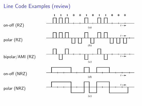
Line Code Examples (review)
on-off (RZ)
polar (RZ)
bipolar/AMI (RZ)
on-off (NRZ)
polar (NRZ)

Line Code Desiderata (review)
Features we want:
◮ Minimum bandwidth (NRZ)
◮ Easy clock recovery (RZ)
◮ Frequently, no DC value (bipolar pulses)
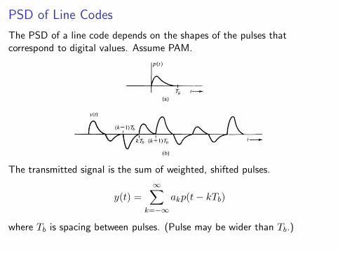
PSD of Line Codes
The PSD of a line code depends on the shapes of the pulses thatcorrespond to digital values. Assume PAM.
The transmitted signal is the sum of weighted, shifted pulses.
y(t) =
∞∑
k=−∞
akp(t− kTb)
where Tb is spacing between pulses. (Pulse may be wider than Tb.)

PSD of Line Codes (cont.)
PSD depends on pulse shape, rate, and digital values {ak}.
We can simplify analysis by representing {ak} as impulse train.
PSD of y(t) is Sy(f) = |P (f)|2Sx(f).
◮ P (f) depends only on the pulse, independent of digital values or rate.
◮ Sx(f) depends only on the bit sequence, and can be altered by thesignaling scheme.
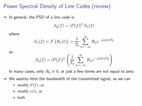
Power Spectral Density of Line Codes (review)
◮ In general, the PSD of a line code is
Sy(f) = |P (f)|2 Sx(f)
where
Sx(f) = F {Rx(t)} =1
Tb
∞∑
n=−∞
Rne−jn2πfTb
so
Sy(f) = |P (f)|2
(
1
Tb
∞∑
n=−∞
Rne−jn2πfTb
)
In many cases, only R0 6= 0, or just a few terms are not equal to zero.
◮ We wantto limit the bandwidth of the transmitted signal, so we can
◮ modify P (f), or
◮ modify x(t), or
◮ both
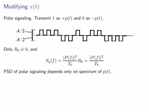
Modifying x(t)
Polar signaling. Transmit 1 as +p(t) and 0 as −p(t),
Only R0 6= 0, and
Sy(f) =|P (f)|2
TbR0 =
|P (f)|2
Tb
PSD of polar signaling depends only on spectrum of p(t).
Modifying x(t) (cont.)
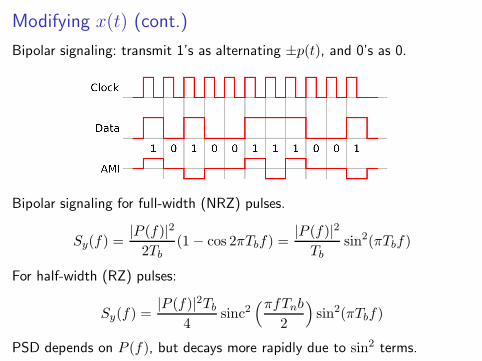
Bipolar signaling: transmit 1’s as alternating ±p(t), and 0’s as 0.
Bipolar signaling for full-width (NRZ) pulses.
Sy(f) =|P (f)|2
2Tb(1− cos 2πTbf) =
|P (f)|2
Tbsin2(πTbf)
For half-width (RZ) pulses:
Sy(f) =|P (f)|2Tb
4sinc2
(πfTnb
2
)
sin2(πTbf)
PSD depends on P (f), but decays more rapidly due to sin2 terms.
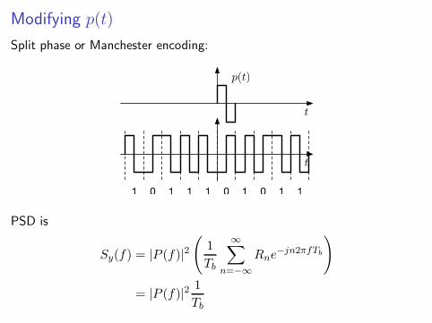
Modifying p(t)
Split phase or Manchester encoding:
t
p(t)
t
1 0 1 1 1 0 1 10 1
PSD is
Sy(f) = |P (f)|2
(
1
Tb
∞∑
n=−∞
Rne−jn2πfTb
)
= |P (f)|21
Tb

Comparison of PSD’s
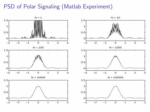
PSD of Polar Signaling (Matlab Experiment)
−3 −2 −1 0 1 2 3
0
0.5
1
1.5N = 1
−3 −2 −1 0 1 2 3
0
0.5
1
1.5N = 10
−3 −2 −1 0 1 2 3
0
0.5
1
1.5N = 100
−3 −2 −1 0 1 2 3
0
0.5
1
1.5N = 1000
−3 −2 −1 0 1 2 3
0
0.5
1
1.5N = 10000
−3 −2 −1 0 1 2 3
0
0.5
1
1.5N = 100000
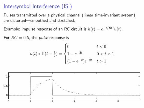
Intersymbol Interference (ISI)
Pulses transmitted over a physical channel (linear time-invariant system)are distorted—smoothed and stretched.
Example: impulse response of an RC circuit is h(t) = e−t/RCu(t).
For RC = 0.5, the pulse response is
h(t) ∗Π(t− 12) =
0 t < 0
1− e−2t 0 < t < 1
(1− e−2)e−2t t > 1
0 1 2 3 4 5
0
0.5
1
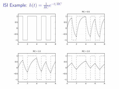
ISI Example: h(t) = 1RC
e−t/RC
0 2 4 6 8
−1
−0.5
0
0.5
1
0 2 4 6 8
−1
−0.5
0
0.5
1
RC = 0.5
0 2 4 6 8
−1
−0.5
0
0.5
1
RC = 1.0
0 2 4 6 8
−1
−0.5
0
0.5
1
RC = 2.0
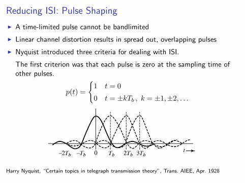
Reducing ISI: Pulse Shaping
◮ A time-limited pulse cannot be bandlimited
◮ Linear channel distortion results in spread out, overlapping pulses
◮ Nyquist introduced three criteria for dealing with ISI.
The first criterion was that each pulse is zero at the sampling time ofother pulses.
p(t) =
{
1 t = 0
0 t = ±kTb , k = ±1,±2, . . .
Harry Nyquist, “Certain topics in telegraph transmission theory”, Trans. AIEE, Apr. 1928
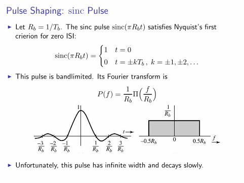
Pulse Shaping: sinc Pulse
◮ Let Rb = 1/Tb. The sinc pulse sinc(πRbt) satisfies Nyquist’s firstcrierion for zero ISI:
sinc(πRbt) =
{
1 t = 0
0 t = ±kTb , k = ±1,±2, . . .
◮ This pulse is bandlimited. Its Fourier transform is
P (f) =1
RbΠ( f
Rb
)
◮ Unfortunately, this pulse has infinite width and decays slowly.
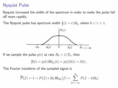
Nyquist Pulse
Nyquist increased the width of the spectrum in order to make the pulse falloff more rapidly.
The Nyquist pulse has spectrum width 12(1 + r)Rb, where 0 < r < 1.
If we sample the pulse p(t) at rate Rb = 1/Tb, then
p(t) = p(t) IIITb(t) = p(t)δ(t) = δ(t) .
The Fourier transform of the sampled signal is
P (f) = 1 = P (f) ∗Rb IIIRb(f) =
∞∑
k=−∞
P (f − kRb)
Nyquist Pulse (cont.)
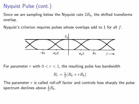
Since we are sampling below the Nyquist rate 2Rb, the shifted transformsoverlap.
Nyquist’s criterion requires pulses whose overlaps add to 1 for all f .
For parameter r with 0 < r < 1, the resulting pulse has bandwidth
Br =12 (Rb + rRb)
The parameter r is called roll-off factor and controls how sharply the pulsespectrum declines above 1
2Rb.

Nyquist Pulse (cont.)
Many pulse spectra satisfy this condition. e.g., trapezoid:
P (f) =
1 |f | < 12(1− r)Rb
1− |f |−(1−r)Rb
2Rb
12(1− r)Rb < |f | < 1
2(1 + r)Rb
0 |f | > 12(1− r)Rb
A trapezoid is the difference of two triangles. Thus the pulse withtrapezoidal Fourier transform is the difference of two sinc2 pulses.
Example: for r = 12 ,
P (f) = 32Λ(
f3
2Rb
)
− 12Λ(
f1
2Rb
)
so the pulse isp(t) = 9
4 sinc2(32Rbt)−
14 sinc
2(12Rbt)
This pulse falls off as 1/t2.
Nyquist Pulse (cont.)
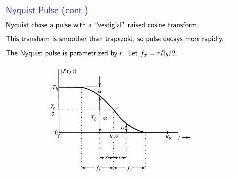
Nyquist chose a pulse with a “vestigial” raised cosine transform.
This transform is smoother than trapezoid, so pulse decays more rapidly.
The Nyquist pulse is parametrized by r. Let fx = rRb/2.
Nyquist Pulse (cont.)
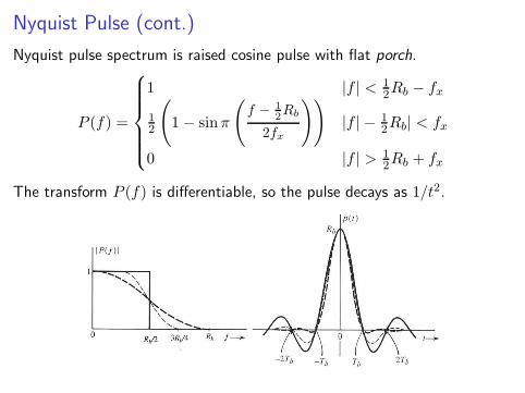
Nyquist pulse spectrum is raised cosine pulse with flat porch.
P (f) =
1 |f | < 12Rb − fx
12
(
1− sinπ
(
f − 1
2Rb
2fx
))
|f | − 12Rb| < fx
0 |f | > 12Rb + fx
The transform P (f) is differentiable, so the pulse decays as 1/t2.
Nyquist Pulse (cont.)
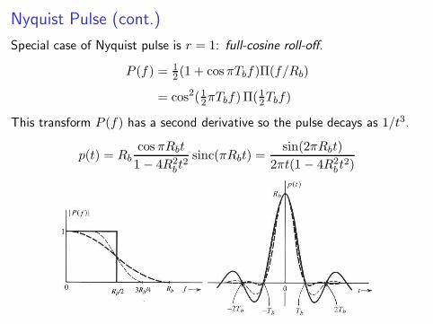
Special case of Nyquist pulse is r = 1: full-cosine roll-off.
P (f) = 12 (1 + cosπTbf)Π(f/Rb)
= cos2(12πTbf)Π(12Tbf)
This transform P (f) has a second derivative so the pulse decays as 1/t3.
p(t) = Rbcos πRbt
1− 4R2b t
2sinc(πRbt) =
sin(2πRbt)
2πt(1− 4R2b t
2)
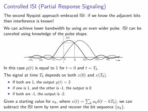
Controlled ISI (Partial Response Signaling)
The second Nyquist approach embraced ISI: if we know the adjacent bitsthen interference is known!
We can achieve lower bandwidth by using an even wider pulse. ISI can becanceled using knowledge of the pulse shape.
In this case p(t) is equal to 1 for t = 0 and t = Tb.
The signal at time Tb depends on both x(0) and x(Tb).
◮ If both are 1, the output y(t) = 2
◮ if one is 1, and the other is -1, the output is 0
◮ if both are -1, the output is -2.
Given a starting value for ak, where x(t) =∑
k akδ(t− kTb), we cansubtract the ISI term by term and recover the bit sequence {ak}.
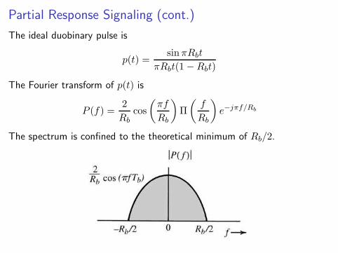
Partial Response Signaling (cont.)
The ideal duobinary pulse is
p(t) =sinπRbt
πRbt(1−Rbt)
The Fourier transform of p(t) is
P (f) =2
Rbcos
(
πf
Rb
)
Π
(
f
Rb
)
e−jπf/Rb
The spectrum is confined to the theoretical minimum of Rb/2.
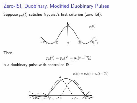
Zero-ISI, Duobinary, Modified Duobinary Pulses
Suppose pa(t) satisfies Nyquist’s first criterion (zero ISI).
Tb 2Tb−2Tb −Tb 0
pa(t)1
t
Thenpb(t) = pa(t) + pa(t− Tb)
is a duobinary pulse with controlled ISI.
Tb 2Tb−2Tb −Tb 0
pb(t) = pa(t) + pa(t− Tb)
t

Zero-ISI, Duobinary, Modified Duobinary Pulses (cont.)
By shift theorem, Pb(f) = Pa(1 + e−j2πTbf )
Since Pb(Rb/2) = 0, most (or all) of the pulse energy is below Rb/2.
We can eliminate unwanted DC component using modified duobinary,where pc(−Tb) = 1, pc(Tb) = −1, and pc(nTB) = 0 for other integers n.
pc(t) = pa(t+ Tb)− pa(t− Tb) =⇒ Pc(f) = 2jPa(f) sin 2πTbf
The transform of pc(t) has nulls at 0 and ±Rb/2.
Tb 2Tb−2Tb −Tb 0
pc(t) = pa(t+ Tb)− pa(t− Tb)
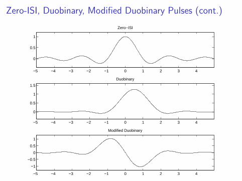
Zero-ISI, Duobinary, Modified Duobinary Pulses (cont.)
−5 −4 −3 −2 −1 0 1 2 3 4
0
0.5
1
Zero−ISI
−5 −4 −3 −2 −1 0 1 2 3 4
0
0.5
1
1.5
Duobinary
−5 −4 −3 −2 −1 0 1 2 3 4
−1
−0.5
0
0.5
1
Modified Duobinary
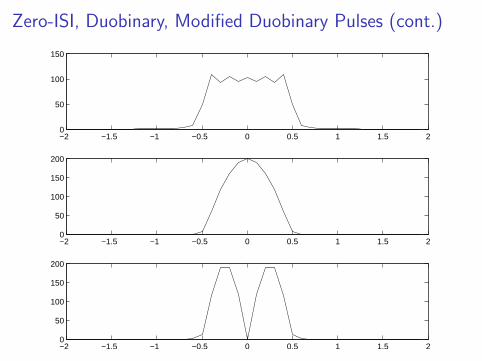
Zero-ISI, Duobinary, Modified Duobinary Pulses (cont.)
−2 −1.5 −1 −0.5 0 0.5 1 1.5 20
50
100
150
−2 −1.5 −1 −0.5 0 0.5 1 1.5 20
50
100
150
200
−2 −1.5 −1 −0.5 0 0.5 1 1.5 20
50
100
150
200
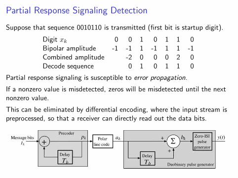
Partial Response Signaling Detection
Suppose that sequence 0010110 is transmitted (first bit is startup digit).
Digit xk 0 0 1 0 1 1 0Bipolar amplitude -1 -1 1 -1 1 1 -1Combined amplitude -2 0 0 0 2 0Decode sequence 0 1 0 1 1 0
Partial response signaling is susceptible to error propagation.
If a nonzero value is misdetected, zeros will be misdetected until the nextnonzero value.
This can be eliminated by differential encoding, where the input stream ispreprocessed, so that a receiver can directly read out the data bits.


