InterVia 3D-P Photoresist is electrodeposited from anaqueous emulsion. It is anaphoretically deposited ontoelectrically-conductive substrates regardless of shape orgeometric complexity. After coating, the substrate isbaked to smooth the film, imaged and developed. After
development, the part can be plated with most commonplating chemistries or etched. After processing, theInterVia 3D-P Photoresist is easily stripped.
ADVANTAGES
Applicable to a wide variety of substrate sizes andgeometries
• Provides uniform, defect free coatings
• Aqueous emulsion
• Coating thickness capability of from 2–10 µm
• Exposure at i -line (365–405 nm) wavelength
• Development in common commercial developers
• Withstands common etch and plating chemistries
• Can be stripped in InterVia 3D-P Remover
PROCESS SEQUENCE
• Preclean
• Rinse
• InterVia 3D-P Photoresist
• Conservation rinse
• DI Rinse
• Forced air dry • Bake
• Rehydrate coating
• Exposure
• Development
• Etch or plate
• Strip
INTERVIA 3D-P BATH MAKE UP
InterVia 3D-P Photoresist is packaged at 20% solids. It isrecommended that the resist be diluted 1:1 with DI water to 10% solids using the procedure below. Prior tofilling process-tanks with chemistry, the tanks should bethoroughly cleaned and rinsed. Please make sure all valves are closed. New 5 micron wound, unsizedpolypropylene filters should be used.
Add ingredients to a clean tank in the order listedbelow with constant mixing
InterVia 3D-P Photoresist: 50% by volume.
DI water <10 microS: 50% by volume
Turn on resist circulation system and allow to circulatefor about four hours. Always analyze the bath for per-cent solids prior to operation and adjust solids if neces-sary. Analyze for TEA and adjust level as necessary.Check thickness. Heat to operating temperature.
If a conservation rinse is available on the equipment,the residual resist solids from dragout can be removed.(Figure 1) The resist solids are re-concentrated by theUltrafilter and returned to the resist coating tank.
If a permeate bath is used for conservation after coat-ing, fill clean tank with high quality DI water. Add NMPto 1.5% of the volume of the Permeate bath. Never addNMP directly into the InterVia 3D-P Photoresist work-ing solution. Always make the addition to the Permeatebath.
Figure 1.Ultrafiltration of Residual Resist solids
INTERVIA 3D-P PHOTORESISTPRODUCT OPERATION
PRODUCTION SCALE COATING
Pre-Clean
Prior to entering the InterVia 3D-P Photoresist, partsmust be thoroughly clean. Failure to use clean parts canresult in resist contamination and uneven coatings. If the part has been freshly plated, make sure that it isthoroughly rinsed with DI water prior to entering thecoating bath. If cleaning is necessary, the type of clean-ing will depend on the surface metal. Your Rohm andHaas Electronic Materials representative can help youmake the selection of chemistry for cleaning. Rinsingafter cleaning is essential. The resist can become con-taminated if the part is not rinsed thoroughly with DI water. Parts with complex 3-D structures will needlonger rinsing.
Coating
InterVia 3D-P Photoresist is applied by anodic elec-trodeposition (Figure 2) . Upon application of a direct current, charged micelles containing all the compo-nents of the resist migrate to the conductive substrate
to form a uniform coating (Figure 3) . Coating thicknessis dependent on temperature as well as substrate as seenin Figure 4 .
It is important to maintain solution level with DI water.
Operating Conditions
Solids content: 9.5–10.5 %
Conductivity: 400–500 microS/cm
Voltage: 100–250 Volts
Current: 1.0 A/dm2 (10 A/ft 2) peak
Circulation: Recommended
Good circulation while parts aresubmerged is one method toprevent pinholes
Temperature: Thickness is dependent ontemperature (see Figure 1)
Temperature control should be within±1 degree C
Wetting time: 40 seconds
Coating time: Potential is applied for 20 seconds.
Ventilation: Required
Filtration: A 5 micron wound, unsizedpolypropylene filter should be usedprior to the ultrafilter
Monitor resist thickness using the supplied procedures.Resist thickness is controlled by additions of InterVia3D-P TC. Make all replenishments into the resist over-
flow sump very slowly (drop-wise) with the circulationon. The favored method of addition is automatic. A consistent need to make large additions of InterVia 3D-P TC indicated that the operation of the system needsto be checked or adjusted.
InterVia 3D-P TC and NMP should be analyzed daily.This will help establish an automatic replenishment schedule. TEA should be monitored once a week.
Rinse
The final rinse is a DI rinse.
Dry
To ensure uniform baking, all drops of water should beblown off before baking. Air knives or an air gun can beused. Ensure the air used is water and oil free. Waterspots when baked form areas which develop slower thansurrounding resist.
Bake (Convection or hotplate)
The coating is dry once the water is blown off, but needs to bake to coalesce the micelles.
This can be done in a convection oven or on a hotplate.Since the purpose of the bake step is to smooth the
micelles, there is not a time advantage to baking on ahotplate.
Convection
Ensure the ovens are free from foreign matter anddebris. Verify the calibration of the temperature con-trollers on a monthly basic. Verify the temperature uni-formity of the oven on a monthly basis.
Bake Temperature: 90–105ºC
Bake Time: 8–15 minutes
Ventilation: Required
Hotplate
Temperature: 90°C
Bake time: 8–15 minutes
Exposure
The coatings must be equilibrated in 40–60% humidity before exposure. Exposure under conditions of lessthan 40% will result in an inability to develop an image.
InterVia 3D-P Photoresist is sensitive at 365–405 nm.Mercury lamps are suited for this wavelength. Many dif-ferent exposure devices can be used. Printer Intensity should be >20 mΩcm2.
Exposure time is dependent on the exposure unit used.On a typical 7kW printer 10–25 seconds can be expect-ed. Exposure dose is about 400 mJ/cm2. Radiometerscan be used to estimate exposure dose and monitor theoutput.
Development
Development should be done in yellow light conditions.
Operating Conditions
InterVia 3D-P Developer at 35°C. Under normal cir-cumstances, the exposed resist will clean in 60–90 sec-onds. Additional time may be required for smaller fea-tures to be cleared. Rinsing after develop should bethorough. Ventilation is required. It is suggested that the developer be filtered with a 10 micron filter. If usedin batch mode, the developer should be replaced whenthe clear time goes over 2 minutes.
8/11/2019 Intervia 3D P Resist UL PF06N045www.microchem.com PDFs_DowPDFs_Dow
InterVia 3D-P Remover at 55°C. Under normal circum-stances strip time should be 30–60 seconds. Ventilationis required. It is suggested that the stripper be filtered
with a 10 micron filter. The stripper should be replaced when the clear time goes over 2 minutes.
Clamp Strip
To ensure good electrical contact during coating, theclamps must be kept clean by stripping off residualresist. Prior to makeup of the clamp strip, check that materials of construction are compatible. Compatiblematerials include: reinforced polyethylene, polypropy-lene, stainless steel and Teflon™ fluoropolymer.
Suggested Clamp-Strip make-up
0.6–0.9% (0.28–0.32N) NaOH at 50–60ºC
Deionised water: 70 parts by volume
Cuposit ™ Z: 3.4 parts by volume
Deionised water: to 100 parts total
Analyze and adjust concentration
Heat to 50–60ºC.
Residual Resist should be removed in 3–5 minutes.
Other grades and forms of sodium hydroxide can beused with appropriate adjustments in amounts.
Control limits
Normality: 0.28–0.32N
BATH REPLACEMENT
InterVia 3D-P Photoresist has a 6-month shelf life in theconcentrate as made if stored between 40–60°F. Undernormal circumstances, there should be no reason toreplace the InterVia 3D-P Photoresist except in cases of contamination. Throughput should be sufficient to
completely replenish the ED bath once every twomonths.
In the event of low throughput, sufficient volumes of the ED bath will regularly need to be removed andreplaced with freshly made up resist solution. This willensure that the ED resist performs at its optimum.
Bacterial Contamination.
Bacteria from the DI water can contaminate the resist bath and multiply. The bacteria take nourishment fromthe photoactive compound and as a result, the bath life will be shortened greatly. Decreased photospeed,
increased development times and increased unexposedfilm loss can be caused by bacterial contamination.
PREVENTIVE MAINTENANCE
• Maintain solution volume with DI water.
• Do not allow solution drag out or spills to dry
• Check flow rates through the permeate system
• Every week check the pre-filters for clogging andchange if necessary
LAB-BENCH SCALE COATINGThe following is a suggested set-up for coating InterVia3D-P Photoresist on a small scale at a lab bench
Power Supply
The power supply should have a voltage range of 0–150 Vdc and an amp range of 0–7
(A suggested power supply for lab use is the SorensenDCS 150-7) The power supply should have zero ripple.The power supply is operated at constant voltage mode where the output voltage is regulated and the output current varied with the load requirement.
Coating Container
The size of the beaker used depends on the size of thepart being coated.
Possible containers for the resist are glass 4-literbeakers, Aldrich chromatography beakers, or plasticTriPour beakers.
For bench-scale coating for feasibility studies, filtrationor ultrafiltration is not needed. However, coating with-out filtration can lead to coatings with more dirt onthem. A 5-micron filter and a small diaphragm pump
are recommended if filtration is desired.
8/11/2019 Intervia 3D P Resist UL PF06N045www.microchem.com PDFs_DowPDFs_Dow
A modified pH probe arm can be wired for electrode-position. A 1/4" polypropylene block can be glued tothe probe holder and copper alligator clamps screwedto the polypropylene as contacts for the lead from the
power supply. Clamps are used to hold the cathode andanode. Stainless steel (either 316 screen or solid 316) isused as the counter-electrode. Anode to cathode dis-tance is about 2 inches. The set-up should be placed ina well-ventilated area. A hood is suggested.
Double safety interlocks are recommended including asafety interlock that requires the hood sash to be downin order for the power supply to operate. Safety First.
Temperature Control
The easiest way to maintain temperature control is by placing the beaker containing the resist into a waterbath at a temperature which will result in the desiredresist thickness.
Resist Make Up
InterVia 3D-P Photoresist is diluted 1:1 with very cleanDI water. Ensure the resist is thoroughly mixed and let come to the desired temperature.
Wafer cleaning:
The metallization on the part should be fresh andclean. Depending on the condition of the metallizationon the part, the part may need to be rinsed with clean
DI water before coating.
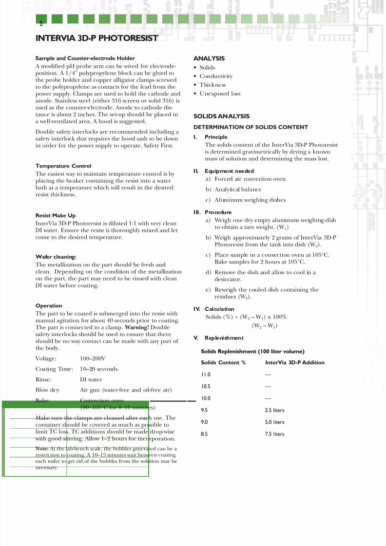
Operation
The part to be coated is submerged into the resist withmanual agitation for about 40 seconds prior to coating.The part is connected to a clamp. Warning! Doublesafety interlocks should be used to ensure that thereshould be no way contact can be made with any part of the body.
Voltage: 100–200V
Coating Time: 10–20 seconds.
Rinse: DI waterBlow dry: Air gun (water-free and oil-free air)
Bake: Convection oven(90–105°C for 8–10 minutes)
Make sure the clamps are cleaned after each use. Thecontainer should be covered as much as possible tolimit TC loss. TC additions should be made drop-wise with good stirring. Allow 1–2 hours for incorporation.
Note: At the lab-bench scale, the bubbles generated can be arestriction to coating. A 10–15 minutes wait between coatingeach wafer to get rid of the bubbles from the solution may benecessary.
ANALYSIS
• Solids
• Conductivity
• Thickness
• Unexposed loss
SOLIDS ANALYSIS
DETERMINATION OF SOLIDS CONTENT
I. Principle
The solids content of the InterVia 3D-P Photoresist is determined gravimetrically by drying a knownmass of solution and determining the mass lost.
II. Equipment needed
a) Forced air convection oven
b) Analytical balancec) Aluminum weighing dishes
III. Procedure
a) Weigh one dry empty aluminum weighing-dishto obtain a tare weight. (W 1)
b) Weigh approximately 2 grams of InterVia 3D-PPhotoresist from the tank into dish (W 2).
c) Place sample in a convection oven at 105°C.Bake samples for 2 hours at 105°C.
d) Remove the dish and allow to cool in adesiccator.
e) Reweigh the cooled dish containing theresidues (W 3).
IV. Calculation
Solids (%) = (W 3 – W 1) x 100%
(W 2 – W 1)
V. Replenishment
Solids Replenishment (100 liter volume)
Solids Content % InterVia 3D-P Addition
11.0 —
10.5 —
10.0 —
9.5 2.5 liters
9.0 5.0 liters
8.5 7.5 liters
8/11/2019 Intervia 3D P Resist UL PF06N045www.microchem.com PDFs_DowPDFs_Dow
The conductivity of a solution is determined usinga commercially available conductivity meter.
II. Material/EquipmentConductivity meter calibrated for use in the rangeof 0–800 µS/cm2
III. Procedure
a) Place approximately 100 ml of working bathinto a 250 ml beaker and allow the sample toequilibrate to 25°C.
b) Calibrate the conductivity probe in accordance with the manufacturer’s instructions.
c) Rinse the conductivity probe thoroughly withalcohol and deionised water.
d) Immerse the conductivity cell into the solutionand measure the conductivity.
e) Rinse probe and store in accordance with man-ufacturer’s instructions.
IV. Thickness
Thickness can be measured using a profilometer orby interferometry. Special programs may need tobe installed in order to measure thick resists.
Cauchy Coefficients may be needed for thicknessmeasurement on some equipment.
GC PROCEDURE FOR ANALYSIS OF INTERVIA 3D-P
PHOTORESIST TC AND NMP
I. Principle
InterVia 3D-P Photoresist TC and NMP contentsshould be analyzed by gas chromatography.
II. Reagents and Apparatus
a) InterVia 3D-P Photoresist TC standard sampleb) N-methyl-2 pyrrolidone
c) Ethylene glycol mono butyl ether
d) Acetone—HPLC-grade or equivalent
e) Analytical balance
f) 10 µliter micro-syringe
g) 100 ml volumetric flask
h) Gas chromatograph—Varian 3600, 6000 orequivalent
i) DB-5 capillary column-1 µm thick phase,30 meter x 32 mm I.D
j) GC autosampler—Varian Vista 8034 or equiva-lent
k) Integrator—SpectraPhysics Data Jet CH1 orequivalent
III. GC Parameters
Column type: 10 feet, 10% FFAPCW80-100AW
Column temperature: 150°C
Injection temperature: 270°C
Detector temperature: 300°C
Detector type: FID
Carrier gas flow: N2 30 ml/min.
IV. Procedurea) Accurately weigh about 0.2g of 2-octanone, 0.1g
N-Methyl-2 Pyrrolidone and 0.15g of ethyleneglycol mono butyl ether into a tared 100 ml vol-umetric flask, dilute to mark with acetone andmix. Label flask as standard.
b) Pipette 10 ml of sample into a 100 ml volumet-ric flask using a TC pipette. Rinse pipette intoflask with acetone. Accurately weigh about 0.15g of ethylene glycol mono butyl ether intothe flask. Dilute to mark with acetone and mix.Label as sample.
c) Set GC temperature program to 160°C isother-mal, with a splitter flow rate of 60 ml/minute(Varian 6000) or 20 ml/min. (Varian 3600).
d) Set integrator peak threshold to 1,000 and peak width to 3. Attenuation should be set accordingto detector response (~32).
Note: Integrator conditions and splitter flow may vary based on instrument types and column age.
e) Using autosampler inject 1 µl of the standardinto the column (perform in duplicate).Record areas of the ethylene glycol mono butylether (~2.87 min.), the InterVia 3D-PPhotoresist TC (~3.32 min.), and the n-methyl-2
pyrrolidone (~3.95 min.).f) Inject 1 µl of sample onto the column (perform
in duplicate). Record the areas of the threepeaks.
Cauchy Coefficients
Resist n1 n2 n3
InterVia 3D-P Photoresist 1.513 6.4E+5 -3E+12
8/11/2019 Intervia 3D P Resist UL PF06N045www.microchem.com PDFs_DowPDFs_Dow
area (Ethylene Glycol Mono Butyl Ether) x std x wt (InterVia 3D-P TC) in std
wt (Ethylene Glycol Mono Butyl Ether) in std X area (InterVia 3D-P TC) in std
RF n-methyl-2 pyrrolidone =
area (Ethylene Glycol Mono Butyl Ether) x (std) x wt (n-methyl-2 pyrrolidone) in std
wt (Ethylene Glycol Mono Butyl Ether) in std X area (n-methyl-2 pyrrolidone) in std
InterVia 3D-P TC% =
area (InterVia 3DP TC) in sample x RF (InterVia 3DP TC) x wt (Ethylene Glycol Mono Butyl Ether) in sample x 10
area (Ethylene Glycol Mono Butyl Ether) in sample
n-methyl-2 pyrrolidone % =
area n-methyl-2 pyrrolidone in sample x rf n-methyl-2 pyrrolidone x wt. ethylene glycol mono butyl ether in sample x 10*
area ethylene glycol mono butyl ether in sample
*10 = dilution factor
It is suggested that NMP level be 1.0–1.5 %
DETERMINATION OF TEA LEVEL INTERVIA 3D-P
PHOTORESIST ANALYSIS
I. Item
Free amine value
II. Principle
A sample is precipitated with alcohol and titratedto a pH 4.8 with hydrochloric acid.
III. Procedure
a) Weigh into a 300 ml beaker approximately 5g
b) Add approximately 100 ml of isopropyl alcohol
c) Titrate with 0.1N HCI to pH 4.8.
IV. Calculation:
Amine value (mEq/g)=HCl (ml) xNormality(N)/Sample weight W
1
(g)
Control range: 0.018~0.024 mEq/g
Replenishment: ED Tank (For 800 liter bath)
TEA (g) =(0.021 Result) x 800 x 149.2
Replenishment: Conservation Rinse Tank
TEA (g) =((0.021 Result) ÷ 3.5) x 800 x 149.2
V. Replenishment
Additions of InterVia 3D-P Photoresist TC shouldbe made according to thickness volume achievedonce all other bath parameters have been opti-mized.
GC analysis results should only serve to monitor thelevel of TC in the bath.
InterVia 3D-P Photoresist TC Replenishment Schedule for 100-liter volume
Thickness is also dependant on TEA content andtemperature. Ensure both are at optimum condi-tions.
FACILITIES
Rohm and Haas Electronic Materials Recommends
coating of substrates with InterVia 3D-P Photoresist andexposure of parts take place in at least a class 10K cleanroom under yellow light. The class of clean room need-ed depends on the feature size being resolved.Temperature control is not critical, and may be adjustedto minimize impact on the phototools. Humidity must be maintained in the exposure area between 40 and60%.
Developing, etching/plating, and stripping can be doneunder normal clean conditions. The developing areashould be equipped with yellow lights.
EQUIPMENTThe coating process should be carried out in a piece of coating equipment designed for use with ED resists andcertified by a Rohm and Haas Electronic Materials rep-resentative. Contact your Rohm and Haas ElectronicMaterials representative for suggested manufacturers.
Ensure tank is clean and contains only compatiblematerial.
Materials of construction: Compatible materials arepolyethylene, polypropylene, stainless steel, Teflon fluo-ropolymer, EPDM, and Kalrez™ perfluoroelastomer.
Incompatible Materials: PVC, CPVC, TYGON, and
Polyurethane.
8/11/2019 Intervia 3D P Resist UL PF06N045www.microchem.com PDFs_DowPDFs_Dow
Heaters: Heaters should be of low watt density with good bathcirculation to avoidoverheating; use of heatexchangers is preferable
Anode Material: 316 Stainless Steel isrecommended
Anode to Cathode Ratio: 1:1
Rectification: A 0–250V power supply isrecommended; amperage isnot limited and is approx.3–4 amperes per square foot; WARNING! Refer toHandling Precautions priorto making up bath
WARNING! At least twosafety interlocks should be
included in the rectificationsystem
New equipment should be leached with a solution of 3% n-methyl-2-pyrrolidone (NMP). This solution shouldbe allowed to circulate through the entire resist system(resist tank, permeate tank, and ultrafilter) at least overnight. The system should then be drained and thor-oughly rinsed with deionized water. See note on DI water quality below.
DI WATER QUALITY
Only very high quality DI water should be used for bathmakeup, evaporation replenishment and rinsing.Pinholes and other coating defects are known to becaused by poor water quality. Conductivity should be<10 microS/cm. The DI water must be kept free of bac-teria. This can be accomplished by running the waterfirst through UV sterilization unit then through consec-utive 0.2 and 0.1 micron membrane filters. Failure touse bacteria free DI water can shorten the life of theInterVia 3D-P Photoresist bath and cause failures in theresist.
PRODUCT DATA
For the specific Product Data values, please refer to theCertificate of Analysis provided with the shipment of the product(s).
HANDLING PRECAUTIONS
Before using this product, consult the Material Safety Data Sheet (MSDS)/Safety Data Sheet (SDS) for detailson product hazards, recommended handling precau-tions and product storage.
CAUTION! Keep combustible and/or flammable prod-ucts and their vapors away from heat, sparks, flames andother sources of ignition including static discharge.Processing or operating at temperatures near or aboveproduct flashpoint may pose a fire hazard. Use appro-priate grounding and bonding techniques to managestatic discharge hazards.
CAUTION! Failure to maintain proper volume level when using immersion heaters can expose tank andsolution to excessive heat resulting in a possible com-bustion hazard, particularly when plastic tanks are used.
STORAGE
Store products in tightly closed original containers at temperatures recommended on the product label.
DISPOSAL CONSIDERATIONS
Dispose in accordance with all local, state (provincial)and federal regulations. Empty containers may containhazardous residues. This material and its containermust be disposed in a safe and legal manner.
It is the user's responsibility to verify that treatment anddisposal procedures comply with local, state (provincial)and federal regulations. Contact your Rohm and HaasElectronic Materials Technical Representative for moreinformation.
8
For Industrial Use Only.This information is based on our experience and is, to the best of our knowledge, true and accurate. However, since conditions for use and handling of
products are beyond our control, we make no guarantee or warranty, expressed or implied, regarding the information, the use, handling, storage or possession of the products,
or the applications of any process described herein or the results sought to be obtained. Nothing herein shall be construed as a recommendation to use any product in viola-
tion of any patent rights.
InterVia, Cuposit, Rohm and Haas, and Rohm and Haas Electronic Materials are trademarks of Rohm and Haas Company, Philadelphia,PA, USA, or its affiliates.Teflon and
Kalrez are trademarks of E.I. DuPont de Nemours and Company, Inc.